Article

A Numerical Study of Dual-Inlet Air-Cooled PV/T Solar Collectors with Various Airflow Channel Configurations

1
School of Environmental and Municipal Engineering, North China University of Water Resources and Electric Power, Zhengzhou 450046, China
2
State Grid Henan Marketing Service Center (Metrology Center), Zhengzhou 450051, China
*
Author to whom correspondence should be addressed.
Sustainability 2022, 14(16), 9897; https://doi.org/10.3390/su14169897
Submission received: 6 June 2022 / Revised: 26 July 2022 / Accepted: 8 August 2022 / Published: 10 August 2022
(This article belongs to the Section Sustainable Engineering and Science)

Abstract

:
The multi-inlet air-cooled photovoltaic/thermal (PV/T) technology not only avoids the poor heat transfer conditions of single-inlet PV/T air collectors but also reduces photovoltaic (PV) peak temperature and improves solar energy utilization. Since air-cooled PV/T collectors use no more than three inlets, the increase in thermal efficiency is significantly more effective. Therefore, a numerical analysis of an air-cooled PV/T solar collector with two side inlets was performed. The heat transfer efficiency and flow characteristics were then investigated for various air channel configurations. Increasing the area of the second inlet improves thermal and electrical efficiency. As the length ratio of the front and rear airflow channels is reduced, the average outlet temperature first decreases and then increases. The heat-exchanging quantity of the dual-inlet air-cooled PV/T collector is minimal. The thermal efficiency of the dual-inlet air-cooled PV/T collector can be elevated by increasing the angle between the solar panel and the bottom plate. However, the average temperature of the solar panels is increased and the photoelectric conversion efficiency decreased. This design will achieve a reduction in carbon emissions and an increase in the proportion of clean energy in a low- or zero-carbon green building.

1. Introduction

A combined solar photovoltaic/thermal (PV/T) system consists of a photovoltaic module and a thermal energy collection module. This system can collect solar energy in the form of electrical energy and thermal energy. PV/T energy systems are a research topic that has attracted much attention in the field of solar energy in recent years because they can further increase the efficiency of solar energy use. The idea of the comprehensive utilization of photovoltaic and photothermal energy was proposed in the 1970s [1], and the photovoltaic–thermal system has been proven to be a feasible method. During the past decades, the research and development of photovoltaic–thermal (PV/T) technology has been carried out by many scholars. Many original systems and products have been suggested. Based on different cooling mediums, PV/T systems can be divided into air-cooled PV/T systems, water-cooled PV/T systems, refrigerant PV/T systems, and heat pipe fluid PV/T systems. The advantage of a refrigerant-based PV/T system is that it can significantly reduce the temperature of photovoltaic cells, has stable performance, and can simultaneously improve the photovoltaic cell conversion efficiency and the coefficient of performance (COP) of the heat pump [2,3]. The PV/T system based on heat pipe fluid has a stable operation performance, smaller thermal resistance, compact structure, and flexible control [4,5,6], which can quickly and effectively reduce the temperature of photovoltaic cells. The disadvantages of these two PV/T systems are high production cost, poor technical reliability, complicated structure, and difficult maintenance. Tripanagnostopoulos et al. [7] found that the thermal efficiency of a water-cooled PV/T system is higher than that of an air-cooled PV/T system because of the higher specific heat capacity and density of water than of air. However, the water-cooled PV/T system also has the problems of high equipment cost, poor operation reliability, difficult maintenance, etc. The air-cooled PV/T system without liquid leakage has the advantages of simple structure, easy installation, and convenient maintenance [8], which has been noticed by more and more researchers.
However, the air-cooled PV/T system is not perfect. There are still shortcomings in low heat exchange efficiency and the overheating of photovoltaic panels. In order to overcome these shortcomings and enhance the photothermal conversion efficiency (PTCE) of the PV/T system, many scholars have studied the structure’s optimization and its thermal characteristics. Shan et al. [9] established the mathematical model of some PV/T systems with different structures, based on an energy balance equation, to analyze the impacts of structural changes on the electrical and thermal characteristics. Assoa and Menezo [10] simulated some air-cooled PV/T collectors using natural or forced ventilation and concluded that the thermal efficiency of the PV/T collectors using forced ventilation was higher than the PV/T collectors using natural ventilation. Hegazy [11], respectively, established theoretical models for four air-cooled PV/T collectors with different flow channel structures. They studied the influence of the flow channel size and air mass flow rate on the photovoltaic and photo-thermal performance of the PV/T collectors. Kasaeian et al. [12] studied the influence of air channel depth on the flow field of a PV/T system by experimental measurement and concluded that reducing the air channel depth can improve the thermal efficiency and has little effect on the electrical efficiency. They also researched the influence of air mass flow and found that with the increase in air mass flow, the improvement of PTCE was more obvious than that of photoelectricity conversion efficiency (PCE). Rekha et al. [13] evaluated the PCE and PTCE of some air-cooled PV/T collectors by using computational fluid dynamics (CFD) technology, and the influence of the mass flow rate and pipe depth on the performance of air-cooled PV/T collectors was investigated. Tonui and Tripanagnostopoulos [14] investigated a PV/T air system by using both experimental and theoretical methods, elevating the heat transfer performance by using thin flat metal sheets hung in the middle of an air channel in the PV/T air configuration and proving that their structural modifications can carry out higher thermal output and photovoltaic module cooling. Ozakin and Kaya [15] analyzed the energy and exergy of an air-based PV/T system by simulation and experiment. They compared the cooling channels placed sparsely and frequent fins with empty channels and found that the exergy efficiency of polycrystalline and single-crystalline panels increased by 70% and 30%, respectively, and the thermal efficiency increased by 55% and 70%, respectively. Mojumder et al. [16] designed an air-cooling PV/T collector with thin rectangular fins, and the influence of the number of ribbed panels, air velocity, and sunshine intensity on the thermal and photovoltaic efficiency was analyzed through experimentation.
Additionally, some novel structures of the air-cooled PV/T solar collection system were designed and researched. Shahsavar and Ameri [17] designed a PV/T air collector where a thin aluminum sheet was suspended in the middle of the air channel and studied its thermal characteristics in natural convection and forced convection and with and without a glass cover. Jin et al. [18] designed an air-cooled PV/T system with a rectangular tunnel as a heat absorber. Compared with a conventional PV/T system, the combined photovoltaic thermal efficiency of their design was 64.72%. Slimani et al. [19] investigated the thermal and electrical performance of a novel air-cooled PV/T system that had a double circulation below and above the photovoltaic module and obtained a combined photovoltaic thermal efficiency of 70%. Ali et al. [20] examined an air-cooled PV/T system that was equipped with a single row of oblique plates inside the air channel and investigated the characteristics of the convective heat transfer and fluid flow of this system. Guo et al. [21] presented and researched a multifunctional PV/T collector which can work in PV/air-heating mode or PV/water-heating mode to satisfy different energy needs.
Although the research on optimizing the structure of an air-cooled PV/T system can enhance its thermal efficiency, the outlet temperature of the air channel is usually higher, which will give rise to the overheating of photovoltaic cells and affect the photoelectric conversion efficiency. Some researchers proposed multi-inlet PV/T systems that can absorb fresh air from the extra inlets to cool the heated air. Rounis et al. [8] carried out a numerical study of air-based multi-inlet building-integrated photovoltaic (BIPV/T) systems and considered that systems with multi-inlets can improve the heat dissipation capacity of photovoltaic panels. Yang and Athienitis [22] improved a BIPV/T system with four inlets and found that the thermal efficiency is 27.1% for this system. Kruglov [23] developed an air-based BIPV/T design methodology and investigated some BIPV/T systems with single or multiple inlets. All the above air-based multi-inlet BIPV/T solar collectors were tilted or vertical, and compared with single-inlet PV/T solar collectors, the extra inlets are parallel to the air channel. Some scholars researched tilted or horizontal air-based multi-inlet BIPV/T solar collectors in which the extra inlets are perpendicular to the air channel. Yang and Athienitis [22] also proposed a tilted dual-inlet air-based BIPV/T system. An experiment on the thermal characteristics of a horizontal dual-inlet air-based open-loop BIPV/T system was carried out by them [24]. They concluded that the dual-inlet design increases thermal efficiency by up to about 5% and increases electrical efficiency marginally. The same author [25] designed a mathematical model for an air-based BIPV/T system with four inlets and five inlets in a cold climate. Numerical research shows that the four inlets and five inlets can increase the thermal efficiency of a PV/T system by over 7% compared to conventional PV/T systems with a single inlet. In addition, their results exhibited that the elevation of thermal efficiency is not visible when the number of inlets is greater than three. Comparing the extra inlets perpendicular to the air channel with the extra inlets parallel to the air channel, the advantage of an air-based BIPV/T system with extra inlets perpendicular to the air channel is more area for laying photovoltaic panels.
The dual-inlet air-cooled PV/T system not only has higher thermal efficiency and lower peak photovoltaic (PV) temperature but also is easy to implement and does not add significant cost. In addition, horizontally positioned air-based PV/T modules have a wide range of applications. Firstly, in order to reduce the use of electricity or fossil fuels, the horizontal air-based PV/T module is suitable for use in preheating fresh air in central air conditioning systems in cold regions. A rectangular air duct is convenient for workers to connect convenient with a central air conditioning system. Secondly, in winter, for recreational vehicles or temporary single-room heating, the horizontal air-based PV/T module could be used as a heating system or just to preheat fresh air. Thirdly, shading is an important part of green buildings. The horizontal air-based PV/T module could be designed as a shading device that can be used for power generation and heat storage. Therefore, in this paper, some horizontal dual-inlet air-cooled PV/T solar collectors with two inlets perpendicular to the air channel were studied, and their thermal performance was analyzed when the configuration of the air channel was changed.

2. Numerical Method

2.1. Geometry Model

Figure 1 displays the structure of a dual-inlet air-cooled PV/T air collector system. Both the front and back photovoltaic panels are 1 m in length. Their width is 0.53 m. The front and back photovoltaic panels are parallel to the adiabatic surface on the bottom. The height of the first and second air channels are 0.045 m and 0.057 m. The fresh air can enter the air channel from the first inlet and the second inlet. Table 1 presents the design parameters of the PV/T collector. Except for two inlets, one outlet, and two photovoltaic panels, the rest of the faces are adiabatic materials.

2.2. Mathematical Model

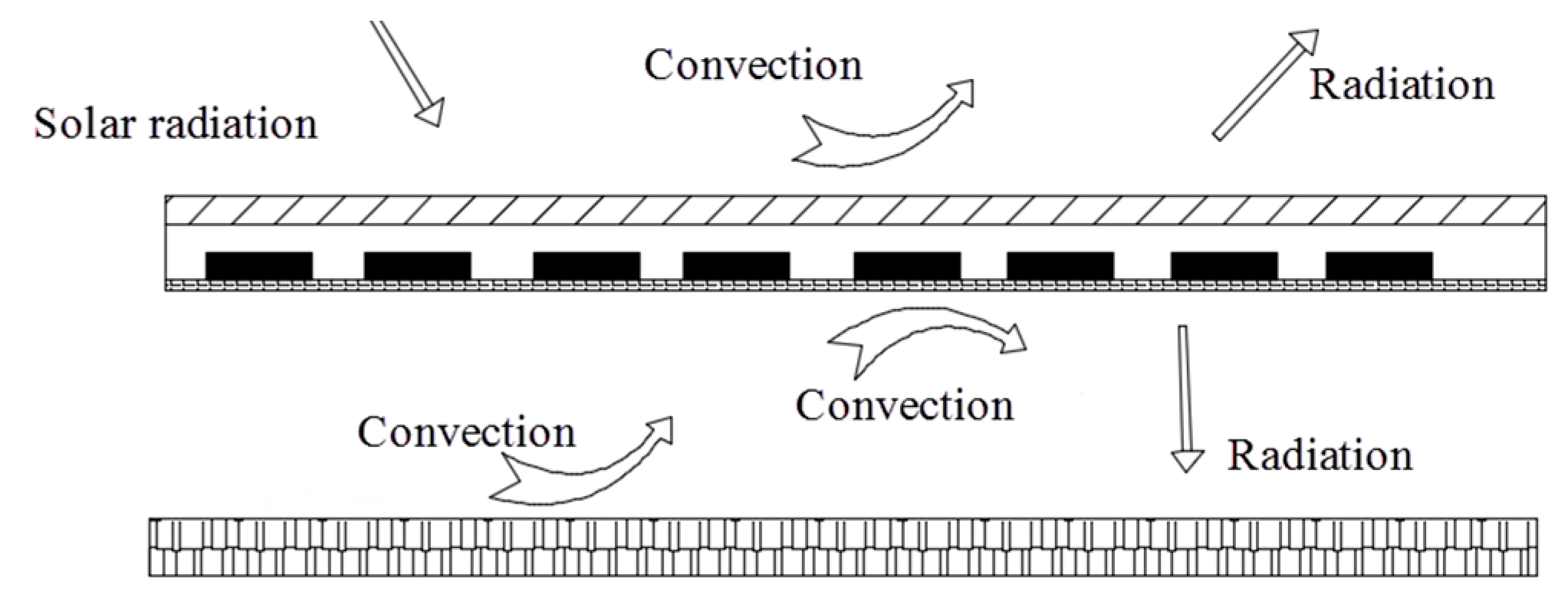
Figure 2 shows the heat transfer process of a dual-inlet air-cooled PV/T system under solar irradiation. Factory-made photovoltaic panels consist of rows of photovoltaic cells protected by glass on the front and plastic on the rear. All photovoltaic cells are vacuum-encapsulated in the clearest polymer. The sunlight is converted into electrical energy after shining on the photovoltaic panel. The heat transfer process includes three parts. Firstly, the sunlight shines on the photovoltaic panel, a part of sunlight is reflected by the surface reflective material, a part of sunlight is converted into electric energy by the photovoltaic panel, and the other part of the sunlight is converted into thermal energy to heat the PV panel. Secondly, with the PV panel heating up, the thermal energy from the upper surface of the PV panel is transferred to the outside environment in the manner of heat convection, heat conduction, and heat radiation. The lower surface of the PV panel exchanges heat with the air and the thermal insulation layer through convection and radiation. Finally, when the temperature of the thermal insulation layer on the bottom increases, it also initiates convective heat exchange to heat the air in the channel.
To simplify the analysis, the following assumptions were made: (1) the system operates under steady-state conditions, (2) two sides and the bottom of the air channel are set as adiabatic, and (3) the thermal capacity of the adhesion layer is ignored considering the equal temperature of the adhesion layer and the photovoltaic cell. Usually, the photovoltaic cell is covered by a layer of glass. The transmittance coefficient of glass is about 0.9. In this paper, we assume that the transmission coefficient of the glass can be included in both the effective utilization coefficient of solar energy and the photovoltaic efficiency.
The energy balance equation of the PV panel is:
θ F I = η e F α I + σ T p v 4 T i n s 4 1 ε p v + 1 ε i n s 1 + h a m b ( T p v T a m b ) + ε σ ( T p v 4 T s k y 4 ) + h t o p ( T p v T ¯ a i r ) + h b o t ( T i n s T ¯ a i r )
In Equation (1), from left to right, the terms respectively represent the absorbed solar energy, the electricity generated by photovoltaic panels, the radiant heat received by the bottom insulation layer, the convective heat absorbed by the surrounding air, the radiant heat received by the sky, heat exchange between photovoltaic panels and air, and heat exchange between bottom insulation panel and air. In the equation, I is solar radiation intensity, F is the packing factor of the solar cell, θ is the effective utilization coefficient of solar energy, η is the electrical efficiency of photovoltaic panels, α is the absorption coefficient, σ is the Stefan–Boltzmann constant, h is the convective heat transfer coefficient, and ε is the emissivity coefficient of the object.
The convective heat transfer coefficient hamb is a function of wind velocity and is extrapolated by the following empirical relationship [26], where υ is the speed of the air:
h a m b = 5.7 + 3.8 υ
The convective heat transfer coefficients htop and hbot can be computed by the following equation:
h a = N u λ a i r D
where λair is the thermal conductivity of air, Nu is the Nusselt number of the airflow, and D is the equivalent diameter. Nu can be estimated by the following correlation [27]:
N u = 0.0214 ( R e 0.8 100 ) P r 0.4 T a i r T 0.4 1 + D L 2 / 3
where Re is the Reynolds number; Pr is the Prandtl number; Tair and T denote the mean air temperature and the wall temperature of the tube, respectively; and L is the length of the front and back PV module. This correlation can fully satisfy engineering calculation accuracy under the following conditions:
2300 < R e < 10 6 ,   0.6 < P r < 1.5 ,   0.5 < T a i r / T < 1.5
For the air in the channel:
m c p ( T o u t T i n ) = A h t o p ( T p v T ¯ a i r ) + A h b o t ( T i n s T ¯ a i r )
In Equation (2), m is the mass flow of air and A is the area of the upper and lower surfaces of the air channel. For the bottom insulation layer:
A σ ( T p v 4 T i n s 4 ) 1 ε p v + 1 ε i n s 1 = A h b o t ( T i n s T ¯ a i r )
In Equation (1), the photovoltaic efficiency as a function of photovoltaic cell temperature is given by [28]:
η e = η r e f 1 β r e f ( T p v T r e f )
The photothermal efficiency can be expressed as:
η t = m c p ( T o u t T i n ) I A

2.3. Numerical Model

Structured hexahedral meshes were generated to complete the grid division of the computational model. The boundary conditions of the fluid region are named as shown in Figure 3. The boundary conditions of each structural boundary of the model are set according to the mathematical model of the heat transfer of the system. The pressure inlet boundary condition was used for the air inlet, the velocity outlet boundary condition for the air outlet, atmospheric pressure for inlet pressure, 20 °C for inlet temperature, and 2 m/s for the outlet air speed. The inner wall adopts no-slip boundary conditions. The upper surface of the PV panel directly receives solar radiation and the lower surface of the photovoltaic panel and the bottom insulating surface exchange heat with the air in the flow channel. The average solar radiation intensity was 1040 W/m2, which is consistent with [24]. The effective utilization coefficient of solar energy and the packing factor of the solar cell is 0.8. The lower surface of the photovoltaic panel is defined as a constant heat flow boundary condition. The material used in the bottom insulation layer is a heat-insulating material, and the external heat exchange phenomenon is not considered, but it accepts the radiation heat transfer of the photovoltaic panel. When the surface temperature of the bottom plate increases, it will produce convective heat transfer with the air in the cavity. The steady simulation was employed using ANASY Fluent.
Getu et al. [29] stated that the prediction accuracy of the k-ε and k-ω turbulence models were both good. The CFD study using the k-ε model showed the best agreement with the measured air and the insulation temperature profiles, and the k-ω model showed the best agreement with the measured PV backside temperature profiles. More accurate air temperature is desired in this paper. Therefore, a standard k-ε turbulence model was used for CFD simulations. In this model, the following equations were used to find the turbulent kinetic energy and its rate of dissipation [30]:
k t + k u i x i = x i D k e f f k x i + G k ε d
k t + ε d u i x i = x i D k e f f ε d x i + C 1 ε ε d k G k C 2 ε ε d 2 k
where Gk is the generation of turbulent kinetic energy due to mean velocity gradients, and Dkeff and eff are the effective diffusivity for k and ε, respectively, which are calculated as shown below:
D k e f f = ν + ν t
D ε e f f = ν + ν t σ ε
The equation for the turbulent kinematic viscosity at each point is:
ν t = C μ k 2 ε
where σε is the turbulent Prandtl number for ε and is assumed as equal to 1.3. Furthermore, the constants C1ε, C2ε, and Cμ have the following values:
C 1 ε = 1.44 ,   C 2 ε = 1.92 ,   C μ = 0.09
Gk is the generation of turbulent kinetic energy, which is common in most turbulence models and is given by:
G k = 2 v t S i j 2
where the strain-rate tensor Sij is written as:
S i j = 0.5 u j x i + u i x j

3. Calculation Verification

3.1. Mesh Independence Verification

The ambient temperature was determined to be T = 20 °C. Five numbers of structured grids are chosen to evaluate the grid independence of the dual-inlet air-cooled PV/T system numerical simulation. The numbers ranged from 1 million to 1.5 million. When the total number of grids amounted to 1.27 million, the monitored average temperature of the dual-inlet air-cooled PV/T system and average inlet and outlet velocity remained constant. So, the grid number of 1.27 million is the solution of grid independence verification, which satisfies the accuracy requirement of numerical simulation. As shown in Figure 4, in the second part of the air channel, three rows of measuring points, which were set by reference [22], are dispersed at different heights. Each row has five points, and three rows are divided into three layers (top, middle, and bottom). Temperature monitoring is carried out in the upper, lower, and middle of the second part of the air channel, respectively.

3.2. Comparison of Experiment and Simulation

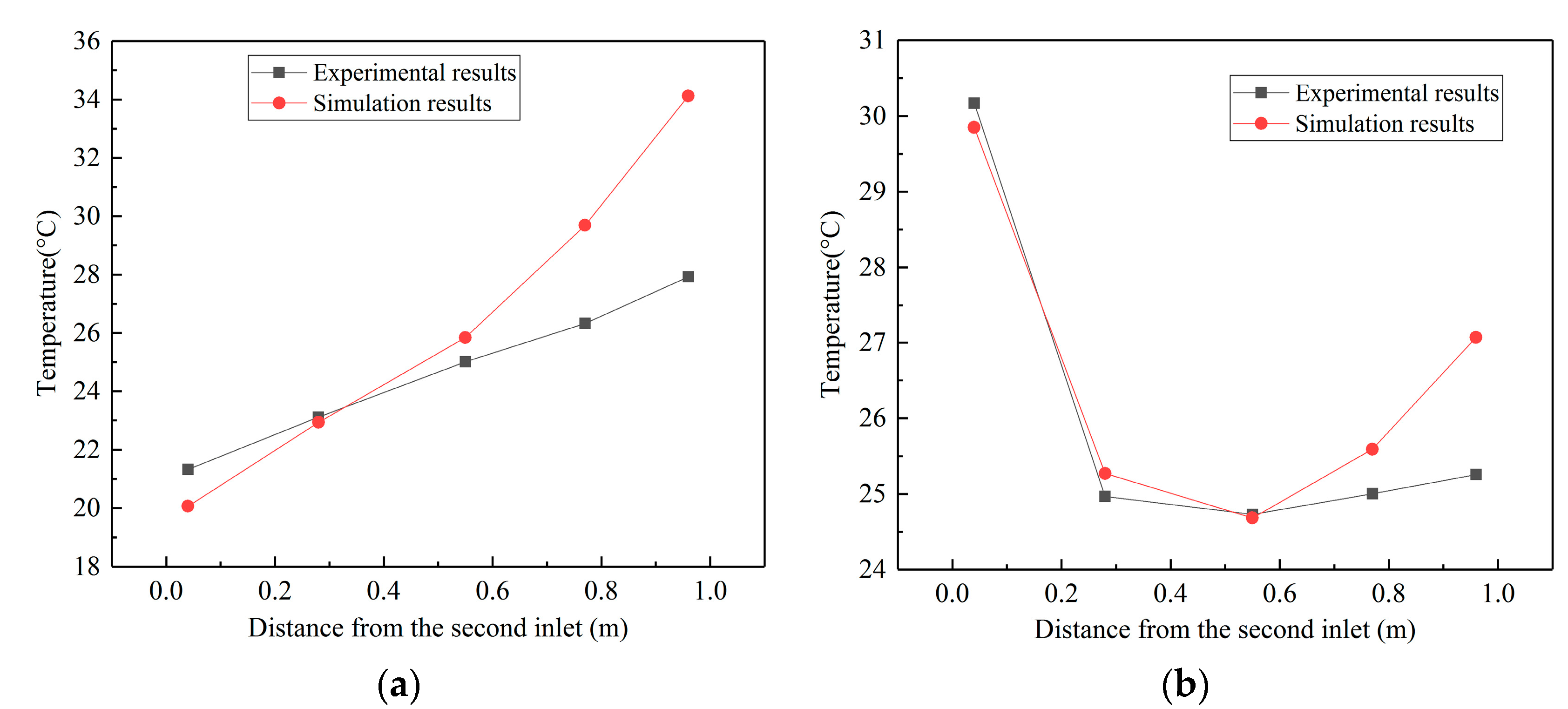
To verify the feasibility of the model, a comparison of the measured and calculated temperature is shown in Figure 5. The red circular dots and lines show the calculated temperatures of 10 points in the top and middle layers in the second part of the air channel. Accordingly, the black square dots and lines show measured temperatures from reference [22] in the same position. The distances of the five columns of temperature points from the outlet are 0.95 m, 0.77 m, 0.53 m, 0.28 m, and 0.03 m, respectively. Figure 5a shows the measured and calculated temperatures of the top layer and Figure 5b shows the corresponding temperature values of the middle layer. From Figure 5, it can be derived that the calculated temperature distribution in the top layer of the air channel agrees with the measured experimental values. At the rear of the top layer, there is a slight difference between the calculated and experimental measured values. The reason why this slight difference appears is that some assumptions were made in constructing the computational model. We assumed that the bottom of the PV/T air collector is the insulation surface, but actually, there is still a small amount of heat that enters the air channel through heat conduction. Therefore, in the back of the second part of the air channel, the measured temperature is a little higher than the calculated temperature. Similarly, the calculated heat transfer efficiency also steadily diminishes in the rear air channel. A comparison of simulated and experimental values in the middle layer in Figure 5b leads to the same conclusion. Indeed, the temperatures obtained from numerical simulation match very well with the measured experimental temperatures. The average departure in Figure 5a is 8.7%. Identically, in Figure 5b it is 3.4%. The simulation model presented in this paper has been shown to be applicable to the study of PV/T systems.

4. Results and Discussion

4.1. Effect of Cross-Sectional Area Ratio of the Inlet and Outlet

A structure schematic of the dual-inlet air-cooled PV/T solar collection system is exhibited in Figure 6. The total length of this PV/T system is 2.04 m and the width is 0.53 m. It contains two air channels. The lengths of the front and rear air channels are equal. X is set as the ratio of the cross-sectional area of the front and rear air passages. X is equal to the ratio of the height of the first air inlet to the height of the outlet. The cross-sectional area ratios, X, for the six working conditions are shown in Table 2.
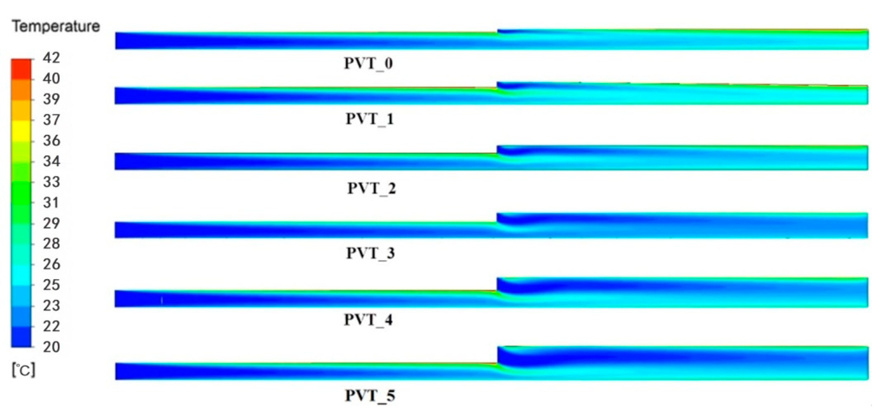
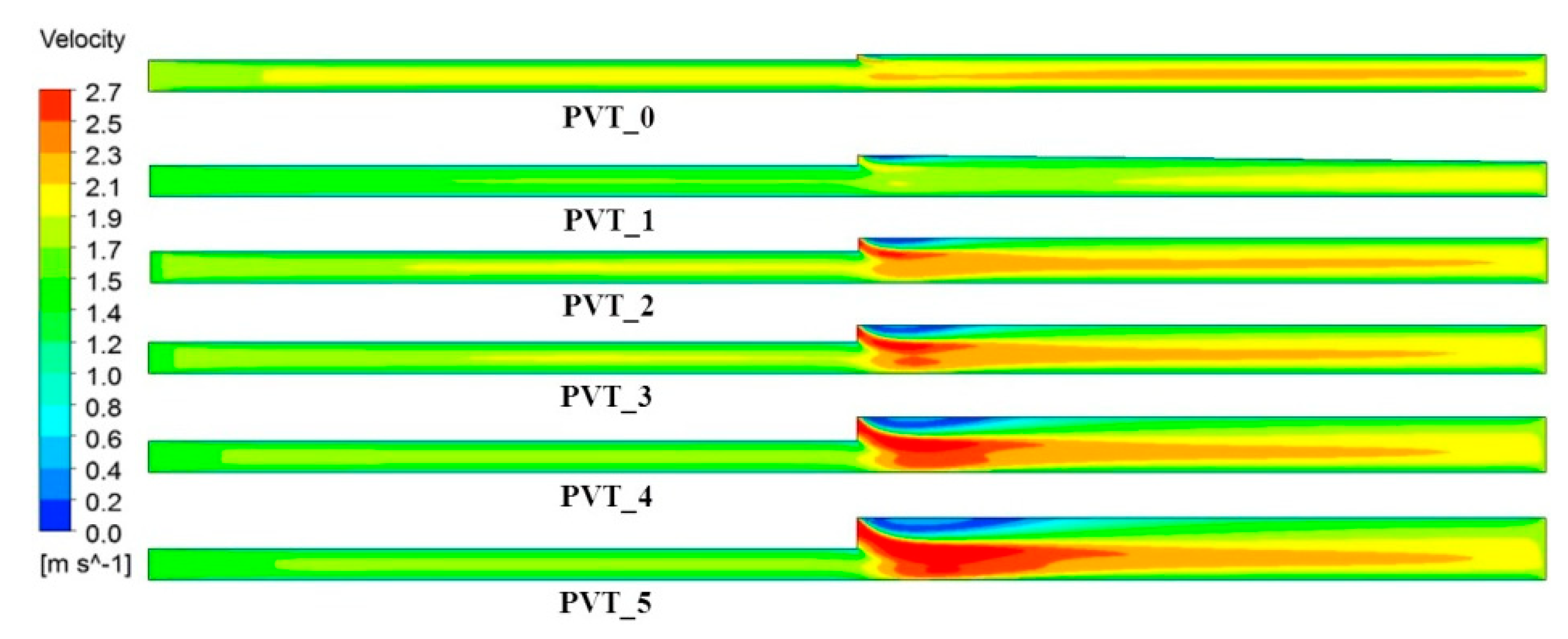
Figure 7 and Figure 8, respectively, show the temperature nephogram and velocity nephogram of the six working conditions in Table 2. As the area of the second inlet increases, the temperature distributions in the front duct change little. In the back duct, however, more air enters the air channel through the second inlet, which reinforces convection heat transfer and enables a more uniform temperature distribution at the outlet. As illustrated in Figure 8, in the case of forced ventilation, the average flow velocity in the back duct increases as the cross-sectional area ratio X decreases. There is a backflow zone near the second inlet, which changes the flow direction and velocity near the second inlet. Its flow direction points downwards about 45 degrees below. The air temperature in the middle layer is significantly reduced. The experiment carried out by Yang and Athienitis [24] shows that the temperature of the middle layer in the second air channel is cooled from 30 to 25 °C by the fresh air from the second inlet. Therefore, the flow characteristic exhibited by us is consistent with the experimental result.
Figure 9 exhibits the total heat exchange amount and the averaged outlet temperature of the six working conditions in Table 2. With the decrease in the cross-sectional area ratio, the averaged outlet temperature decreases, because inlet velocity is constant and the total mass flow certainly increases. The maximum value of heat exchange was found to be between X = 0.562 and X = 0.645. The maximum thermal efficiency is about 45.36%. In practical applications, the outlet temperature can be controlled by changing the area ratio of the two inlets. The maximum heat exchange volume can also be obtained by optimizing the area ratio of the two inlets.
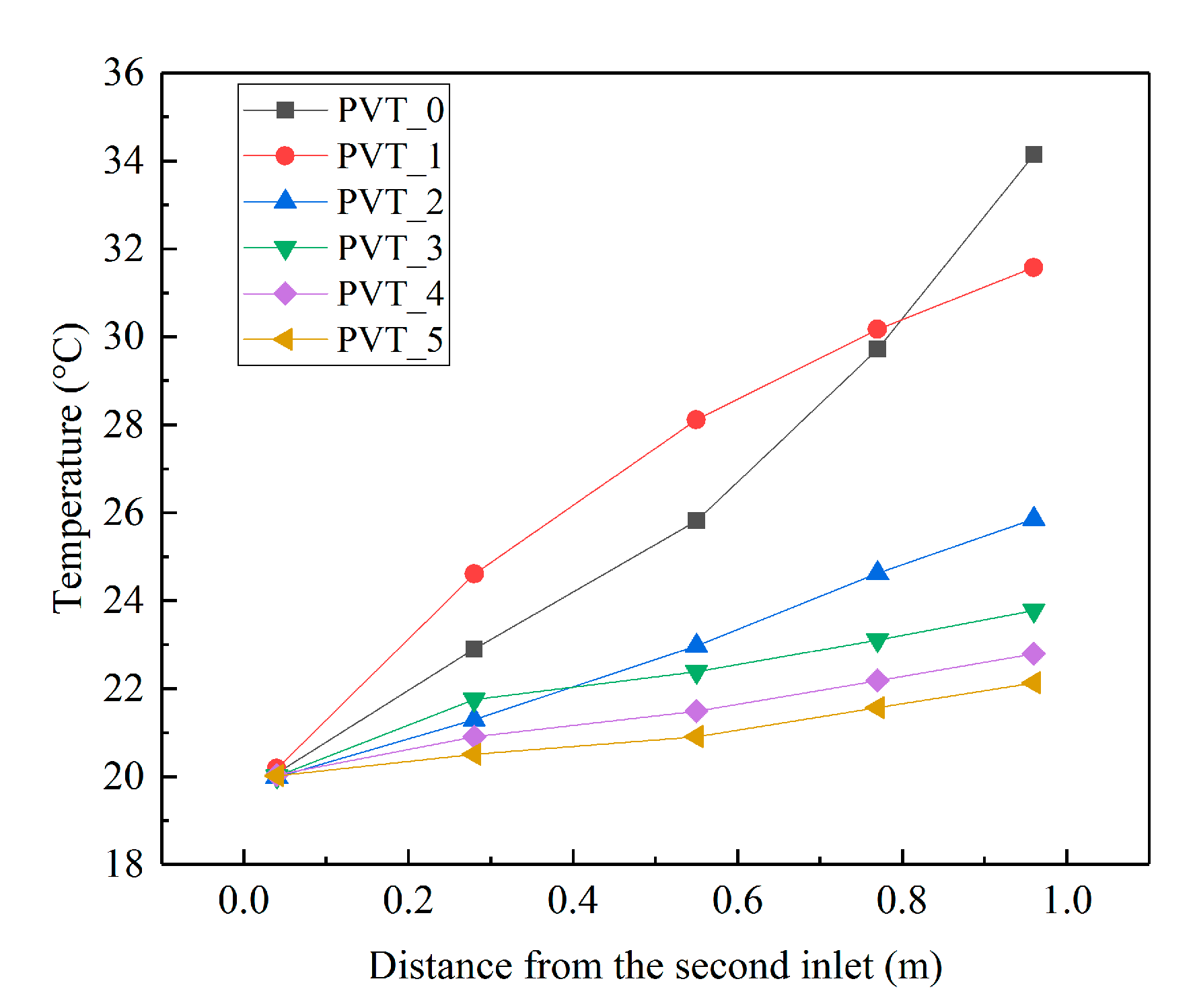
The top and middle layer temperature of working conditions with six cross-sectional area ratios are shown in Figure 10 and Figure 11. It is found that the top layer temperature in the second part of the air channel gives a rising trend. Obviously, with the decrease in the inlet and outlet cross-sectional area ratio X, the rising trend tends to abate. The reason for this is that when X becomes smaller, the area of the second inlet would increase, and the airflow from the inlet also would increase. It can be seen from the temperature curves in Figure 11 that when X = 0.847 and X = 0.746, the middle temperature in the second part of the air channel first decreases and then increases. When X = 0.690, X = 0.645, X = 0.562, and X = 0.5, the middle temperature gradually decreases and finally tends to be flat. This phenomenon indicates that more air getting into the air channel from the second inlet resulted in the temperature distribution being more regular. The calculated photovoltaic efficiencies of the PV/T collectors (six cross-sectional area ratios) are shown in Table 3. The maximum photovoltaic efficiency is 11.25% at X = 0.5. The improved photovoltaic efficiency by decreasing the temperature of the photovoltaic panel is not obvious.

4.2. Effect of the Length Ratio of the Front and Back Air Channel

To study the thermal characteristics of the dual-inlet air-cooled PV/T solar collector with different lengths of the front and back air channels, the effects of different lengths of the front and back air channels are analyzed in this section. We keep the length of the total solar collector unchanged and keep a constant air mass flow in the outlet. Set Y as the length ratio of the front and back air channels, Y = length_first/length_second. In this paper, the length ratios of seven working conditions are set to Y = 1.865, Y = 1.331, Y = 1.000, Y = 0.799, Y = 0.667, Y = 0.571, and Y = 0.536. The detailed settings are shown in Table 4.
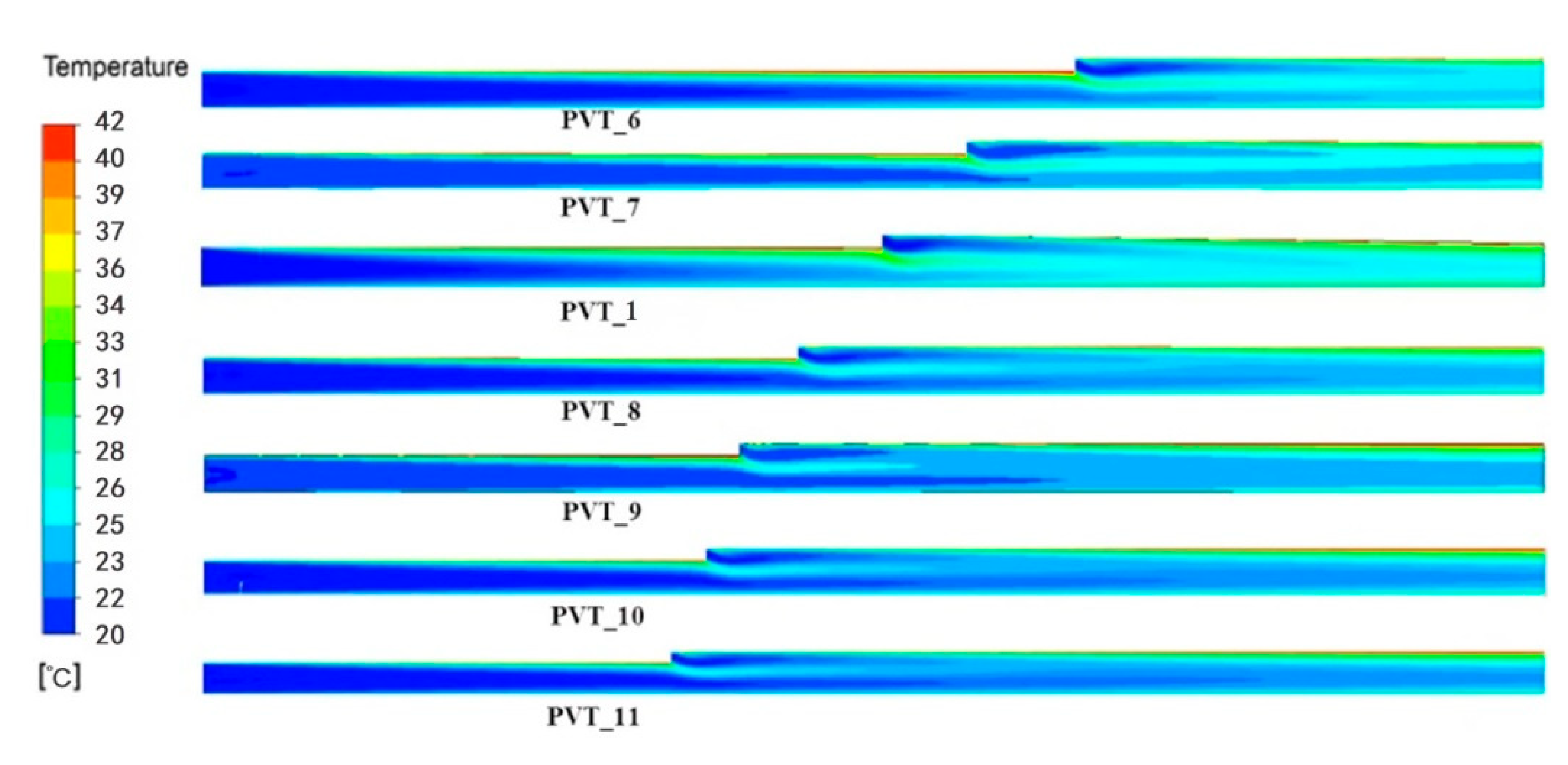
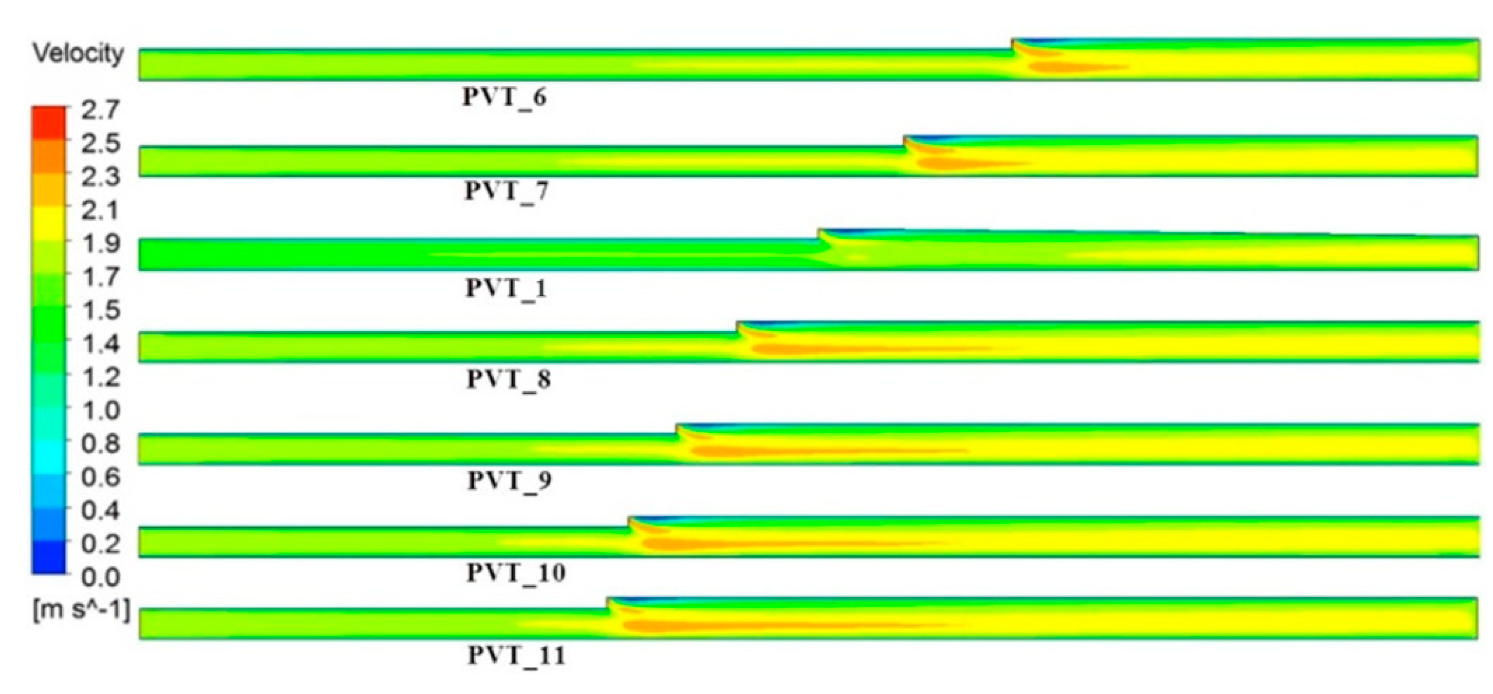
The temperature nephogram and velocity nephogram of seven air channel length ratios in the longitudinal section of the solar collector are shown in Figure 12 and Figure 13. It can be seen in Figure 12 that different length ratios have an effect on the temperature of the front and back parts of the air channel. As the length of the second part of the air channel increases, the air temperature distribution in this channel becomes more non-uniform. It is found that when Y decreases, the temperature distribution of the outlet gradually emerges and the upper temperature is higher than the lower temperature. The air that gets into the air channel from the second inlet has a greater impact on the development of flows. In the forced ventilation state, the influence of the air channel length ratio Y on the airflow state in the air channel is shown in Figure 13. It can be seen that the air velocity of the first part of the air channel does not change much, but after the second inlet there is a high-velocity region. When the air channel length ratio Y is 1.865, the high-velocity region has an impact on the velocity distribution of the outlet. When Y decreases, the velocity distribution of the outlet becomes more uniform.
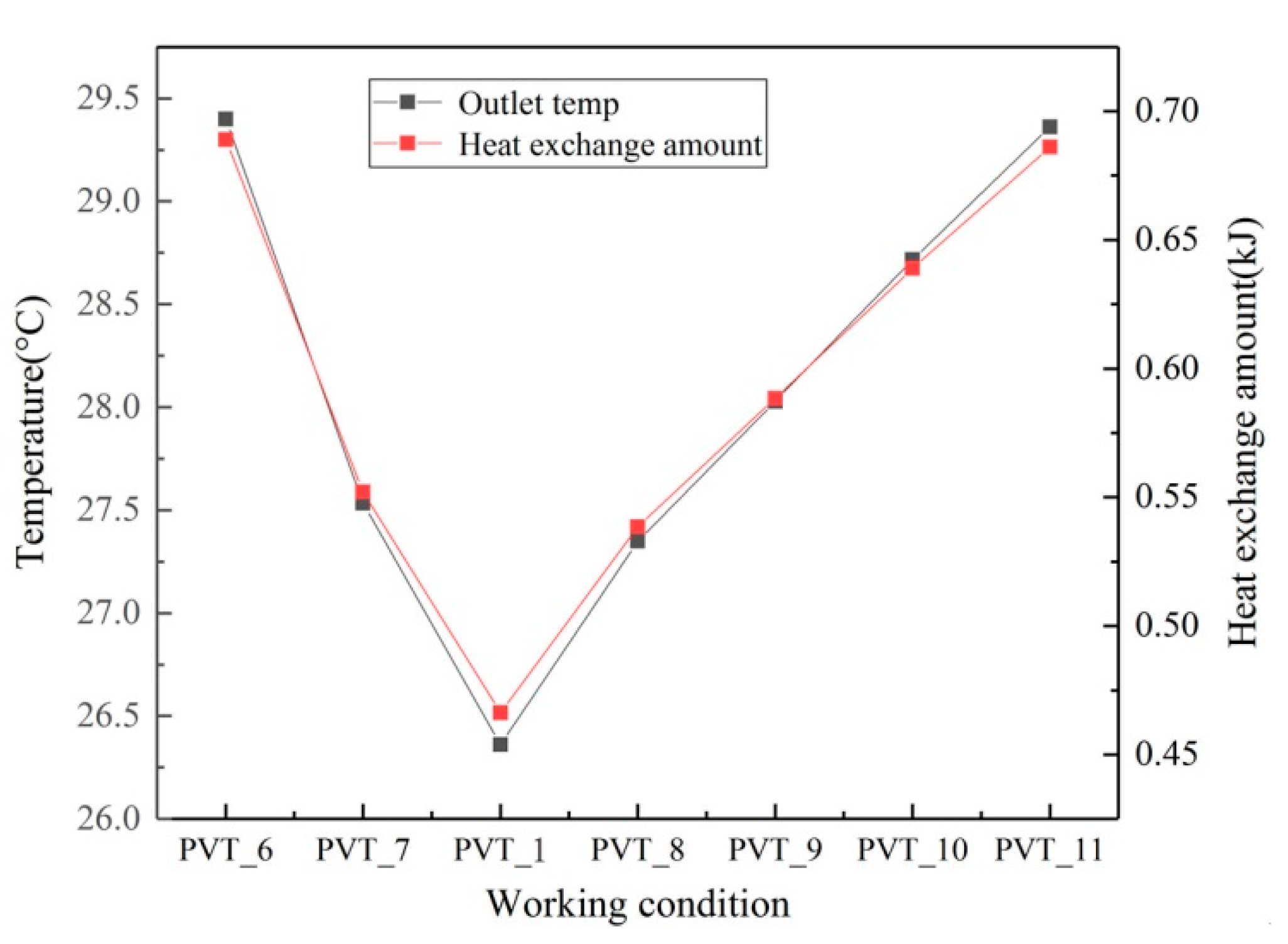
Figure 14 shows the averaged outlet temperatures and the total heat exchange amounts of seven kinds of air channel length ratios. With a decrease in the air channel length ratio, the averaged outlet temperature first decreases and then increases. The calculated maximum thermal efficiency is about 62.14% at Y = 1.865. When Y = 1, the average outlet temperature and total heat exchange of this system are the smallest. Although the photothermal efficiency of the system is the lowest at this time, with lower air channel temperature and photovoltaic panel temperature, the photoelectric efficiency will increase. In the actual application of the dual-inlet air-cooled PV/T solar collection system, the position of the second inlet can be adjusted to control the outlet temperature according to different usage requirements.
The top and middle layer temperatures of working conditions with seven air channel length ratios are shown in Figure 15 and Figure 16. With the length of the air channel of the second part increasing, the top layer temperature in the second part of the air channel shows a rising trend. When Y = 1, the rate of temperature increase in the top layer is greatest. When Y decreases, the middle layer temperature is impacted by the air which gets into the air channel from the second inlet, and the middle layer temperature first decreases and then slightly increases, as exhibited in Figure 16. The calculated photovoltaic efficiencies of the PV/T collectors (seven air channel length ratios) are shown in Table 5. The maximum photovoltaic efficiency is 11.19% at Y = 1. However, under this condition, the thermal efficiency is the smallest.

4.3. Effect of the Angle between the Photovoltaic Panel and the Bottom Panel in the Second Part

In this section, the thermal characteristics of the dual-inlet air-cooled PV/T solar collector with different angles between the photovoltaic panel and the bottom panel in the second part of the air channel were studied. The total length of the air channel was fixed as 2 m. The first part and second part of the air channel are both 1 m. The width of the air channel is 0.5 m. The height of the first inlet is 0.0045 m, and the height of the second inlet is 0.00153 m. Setting the angle between the photovoltaic panel and the bottom panel in the second part of the air channel is φ. In this paper, the angle φ is set as φ = 0°, φ = 1°, φ= 2°, φ = 3°, and φ = 4°, respectively. The outlet air mass flow must be kept constant. The schematic diagram of the dual-inlet air-cooled PV/T solar collector is shown in Figure 17, and the angle φ for five working conditions is shown in Table 6.
The temperature nephogram and velocity nephogram obtained at five angles φ in the longitudinal section of the solar collector are shown in Figure 18 and Figure 19. The angle φ has little effect on the temperature distribution of the first part of the air channel. However, as the angle φ increases from 0° to 4°, in the second part of the air channel, the upper layer temperature becomes higher and higher. As shown in Figure 19, when the angle φ increases from 0° to 4°, it can be obviously seen that the flow velocity in the second part of the air channel reveals a decreasing trend, and the velocity distribution in the air outlet becomes more and more uniform.
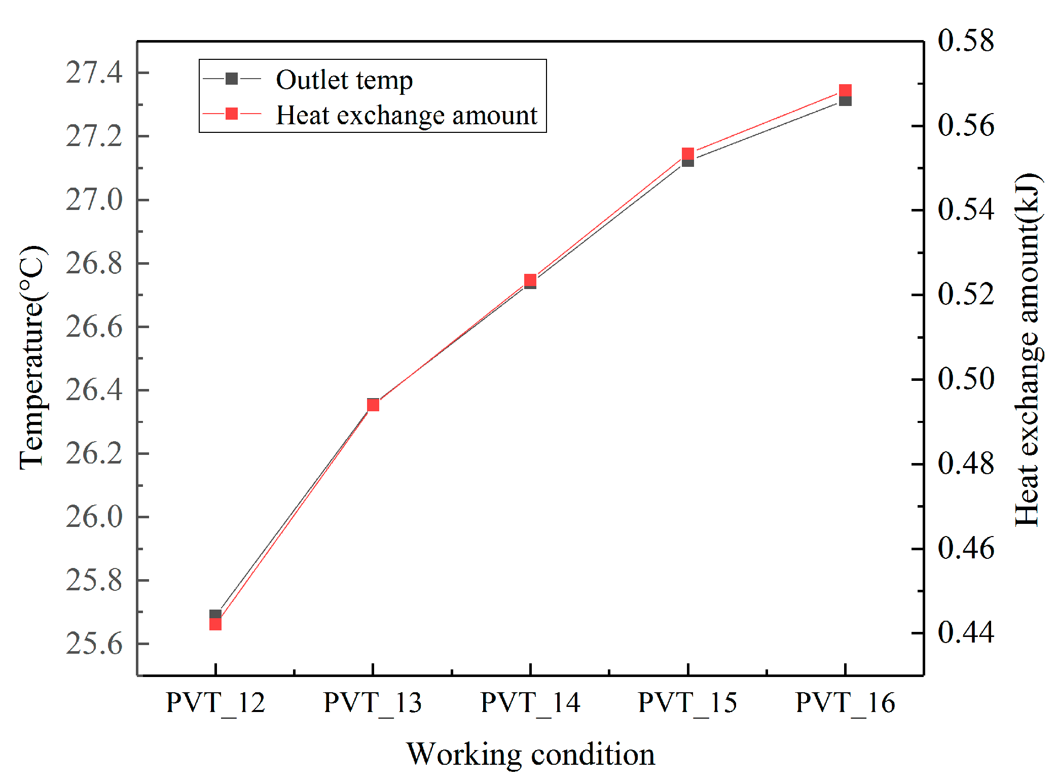
The average outlet temperature and total heat exchange of five angles φ are shown in Figure 20. As the angle increases to 4 degrees, both the average outlet temperature and the heat exchange amount gradually increase. The calculated maximum thermal efficiency is about 51.70% at φ = 4°. The reason for this situation is that on account of the constant mass flow, as the angle φ increases, the cross-sectional area of the outlet will increase. The velocity of the air in the flow channel is going to increase. The air will spend more time in the air channel and obtain more heat from the PV plane. A high vertical temperature gradient can be seen in the upper part of the second air passage, which means that a large amount of heat is gathered in there.
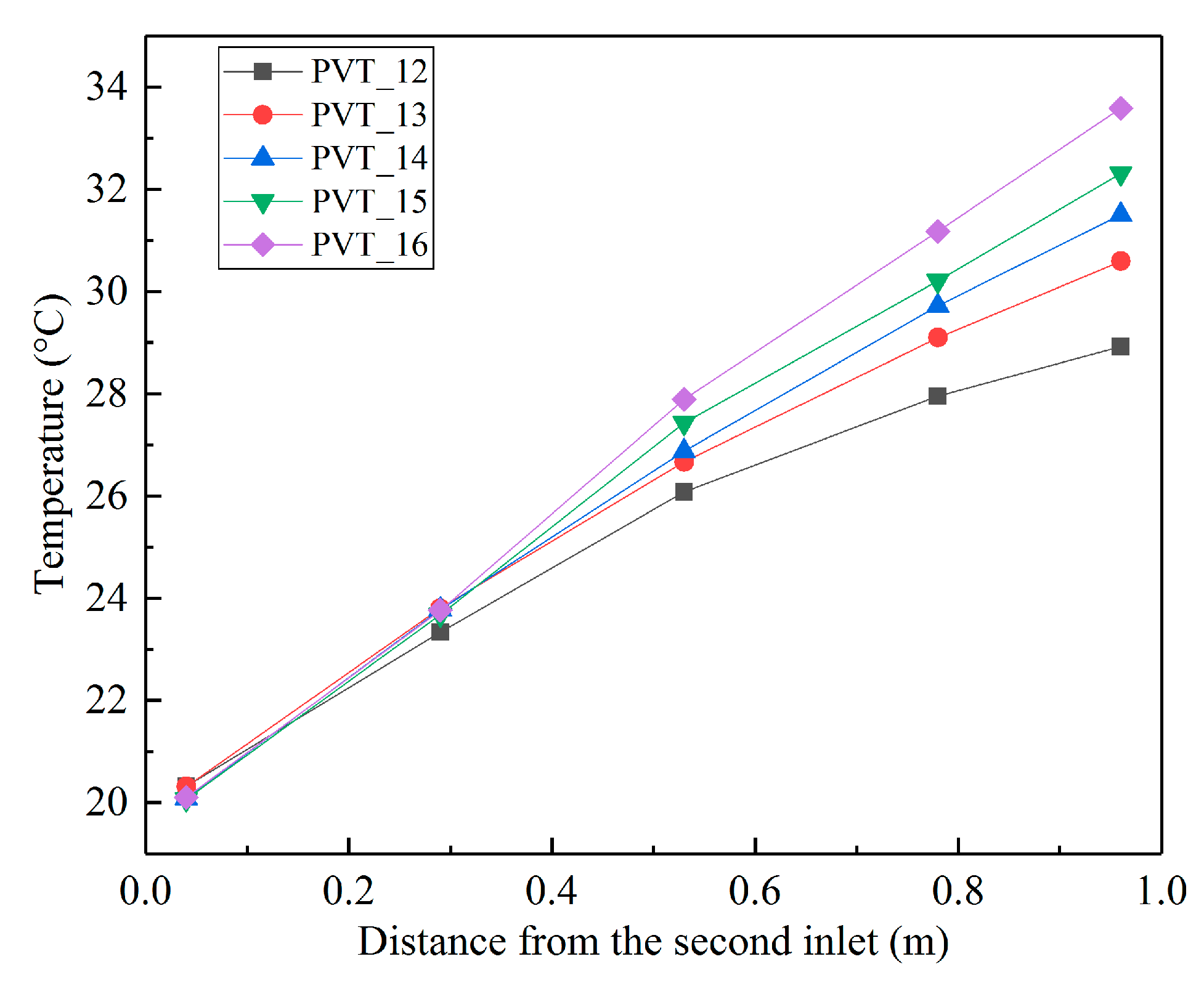
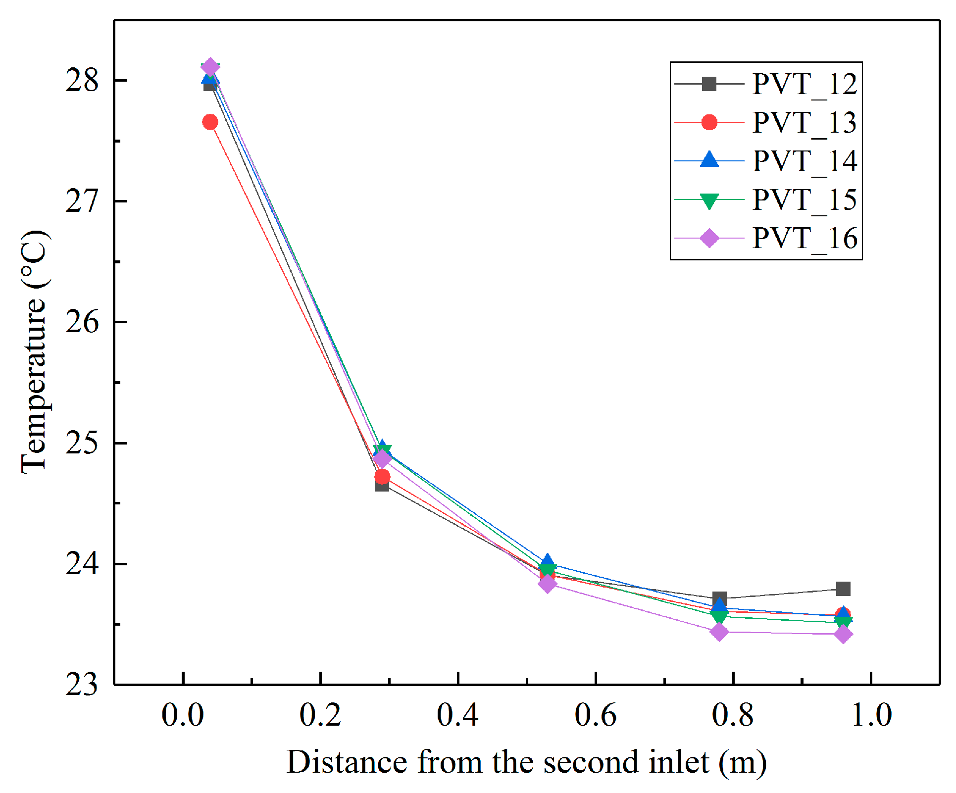
The temperatures of the top and middle layers of the dual-inlet air-cooled PV/T solar collector with different angles φ are shown in Figure 21 and Figure 22. It can be observed that with an increase in the angle φ, the top layer temperature in the second part of the air channel is higher; on the contrary, the middle layer temperature in the second part of the air channel is lower. When the angle φ is 4°, the temperature rise in the top layer is the fastest rate. However, in the middle layer, the temperature trends are pretty much the same. The heat obtained by air in the second part of the air channel is almost all concentrated in the upper part. The calculated photovoltaic efficiencies of the PV/T collectors (five angles) are shown in Table 7. The maximum photovoltaic efficiency is 11.19% at φ = 0°. However, under this condition, the thermal efficiency is the smallest.

5. Conclusions

Compared with the water-cooled PV/T system, the air-cooled PV/T solar system without liquid leakage is easy to install and requires minimal maintenance. In the same way, the air-cooled PV/T solar system can further improve the utilization of solar energy. Hence, it is ideal for use in a BIPV/T system. Multi-inlet air-cooled BIPV/T systems can be divided into two types: sky-inlet and side-inlet BIPV/T systems. The sky-inlet BIPV/T system takes up more area for laying photovoltaic panels. Both of them can elevate the thermal efficiency and reduce the temperature of the PV panel. However, the elevation of thermal efficiency is not visible when the number of inlets is greater than three. In this study, the air-cooled PV/T solar collectors with two side inlets were analyzed by the method of numerical calculation. The heat transfer efficiency and flow characteristics were investigated when the airflow channel configuration was changed. The following conclusions can be drawn:
(1)
As the area of the second inlet increases, more air getting into the second inlet enhances the convection heat transfer as the cross-sectional area ratio X is reduced, and the temperature distribution in the back air channel is more uniform. The maximum thermal efficiency is about 45.36% at X = 0.562. The maximum photovoltaic efficiency is 11.25% at X = 0.5.
(2)
As the length ratio Y of the front and back air channel is reduced, the averaged outlet temperature first decreases and then increases. There is a minimum heat-exchanging quantity of the dual-inlet PV/T air collector between Y = 1.331 and Y = 0.799. The calculated maximum thermal efficiency is about 62.14% at Y = 1.865. The maximum photovoltaic efficiency is 11.19% at Y = 1.
(3)
Along with the increase in angle φ, the average temperature of the outlet gradually rises. Although the calculated maximum thermal efficiency is about 51.70% at φ = 4°, the photovoltaic efficiency is the smallest. A large amount of heat gathers in the upper part of the second air passage, which is not conducive to cooling the photovoltaic panels.

Author Contributions

Conceptualization, Z.K. and Z.L.; methodology, Z.K. and G.S.; software, Z.L.; validation, Z.K., Z.L and Q.Y.; formal analysis, Z.L.; investigation, Z.K. and Z.L.; resources, Q.Y.; data curation, Z.K. and Q.Y.; writing—original draft preparation, Z.L. and Q.Y; writing—review and editing, Z.K. and Q.Y; visualization, Z.K. and Z.L.; project administration, G.S.; funding acquisition, G.S. All authors have read and agreed to the published version of the manuscript.

Funding

This research was funded by the Projects of Higher Education Teaching Reform and Practice in Henan Province (No. 2021SJGLX012Y, No. 2021SJGLX155).

Institutional Review Board Statement

Not applicable.

Informed Consent Statement

Not applicable.

Data Availability Statement

Not applicable.

Conflicts of Interest

The authors declare no conflict of interest. The funders had no role in the design of the study; in the collection, analyses, or interpretation of data; in the writing of the manuscript, or in the decision to publish the results.

Abbreviations

Nomenclature
Aarea, m2
cpspecific heat capacity, kJ/kg K
Dkeffeffective diffusivity for k
Dεeffeffective diffusivity for εd
Fpacking factor
Gkproduction of turbulent kinetic energy, J
kturbulent kinetic energy, J
Hheight, m
hconvective heat transfer coefficient, W/m2 K
Isolar radiation intensity, W/m2
LLength, m
mmass flow rate, kg/s
Sijstrain-rate tensor
Ttemperature, oC
vflow velocity, m/s
Wwidth, m
Xcross-sectional area ratio of the front and back air channel
Ylength ratio of the front and back air channels
ν kinematic viscosity, m2/s
ν t turbulent kinematic viscosity, m2/s
αabsorption coefficient
μdynamic viscosity, N·s/m2
ηphotovoltaic efficiency
λthermal conductivity, W/m K
τtransmission coefficient
γkinematic viscosity, m2
εemissivity coefficient
εdrate of dissipation of turbulent kinetic energy
σStefan–Boltzmann Constant
σεturbulent Prandtl number for εd
φangle, deg
θeffective utilization coefficient of solar energy
Subscripts
eelectrical
tthermal
airairflow
ambambient air
insinsulation backplane
pvphotovoltaic panel
skysky
toptop
botbottom
refreference value at reference conditions

References

  1. Wolf, M. Performance analyses of combined heating and photovoltaic power systems for residences. Energy Convers. 1976, 16, 79–90. [Google Scholar] [CrossRef]
  2. Bandaru, R.; Muraleedharan, C.; Kumar, P. Modelling and dynamic simulation of solar-thermal energy conversion in an unconventional solar thermal water pump. Renew. Energy 2019, 134, 292–305. [Google Scholar] [CrossRef]
  3. Safijahanshahi, E.; Salmanzadeh, M. Performance simulation of combined heat pump with unglazed transpired solar collector. Sol. Energy 2019, 180, 575–593. [Google Scholar] [CrossRef]
  4. Hu, M.; Zheng, R.; Pei, G.; Wang, Y.; Li, J.; Ji, J. Experimental study of the effect of inclination angle on the thermal performance of heat pipe photovoltaic/thermal (PV/T) systems with wickless heat pipe and wire-meshed heat pipe. Appl. Therm. Eng. 2016, 106, 651–660. [Google Scholar] [CrossRef] [Green Version]
  5. Moradgholi, M.; Nowee, S.M.; Abrishamchi, I. Application of heat pipe in an experimental investigation on a novel photovoltaic/thermal (PV/T) system. Sol. Energy 2014, 107, 82–88. [Google Scholar] [CrossRef]
  6. Zhang, B.; Lv, J.; Yang, H.; Li, T.; Ren, S. Performance analysis of a heat pipe PV/T system with different circulation tank capacities. Appl. Therm. Eng. 2015, 87, 89–97. [Google Scholar] [CrossRef]
  7. Tripanagnostopoulos, Y.; Nousia, T.; Souliotis, M.; Yianoulis, P. Hybrid photovoltaic/thermal solar systems. Sol. Energy 2002, 72, 217–234. [Google Scholar] [CrossRef]
  8. Rounis, E.D.; Athienitis, A.K.; Stathopoulos, T. Multiple-inlet Building Integrated Photovoltaic/Thermal system modelling under varying wind and temperature conditions. Sol. Energy 2016, 139, 157–170. [Google Scholar] [CrossRef] [Green Version]
  9. Shan, F.; Tang, F.; Cao, L.; Fang, G. Comparative simulation analyses on dynamic performances of photovoltaic–thermal solar collectors with different configurations. Energy Convers. Manag. 2014, 87, 778–786. [Google Scholar] [CrossRef]
  10. Assoa, Y.-B.; Ménézo, C. Dynamic study of a new concept of photovoltaic–thermal hybrid collector. Sol. Energy 2014, 107, 637–652. [Google Scholar] [CrossRef]
  11. Hegazy, A.A. Comparative study of the performances of four photovoltaic/thermal solar air collectors. Energy Convers. Manag. 2000, 41, 861–881. [Google Scholar] [CrossRef]
  12. Kasaeian, A.; Khanjari, Y.; Golzari, S.; Mahian, O.; Wongwises, S. Effects of forced convection on the performance of a photovoltaic thermal system: An experimental study. Exp. Therm. Fluid Sci. 2017, 85, 13–21. [Google Scholar] [CrossRef]
  13. Rekha, L.; Vazhappilly, C.V.; Melvinraj, C. Numerical simulation for solar hybrid photovoltaic thermal air collector. Procedia Technol. 2016, 24, 513–522. [Google Scholar]
  14. Tonui, J.; Tripanagnostopoulos, Y. Air-cooled PV/T solar collectors with low cost performance improvements. Sol. Energy 2007, 81, 498–511. [Google Scholar] [CrossRef]
  15. Özakin, A.N.; Kaya, F. Effect on the exergy of the PVT system of fins added to an air-cooled channel: A study on temperature and air velocity with ANSYS Fluent. Sol. Energy 2019, 184, 561–569. [Google Scholar] [CrossRef]
  16. Mojumder, J.C.; Chong, W.T.; Ong, H.C.; Leong, K. An experimental investigation on performance analysis of air type photovoltaic thermal collector system integrated with cooling fins design. Energy Build. 2016, 130, 272–285. [Google Scholar] [CrossRef]
  17. Shahsavar, A.; Ameri, M. Experimental investigation and modeling of a direct-coupled PV/T air collector. Sol. Energy 2010, 84, 1938–1958. [Google Scholar] [CrossRef]
  18. Jin, G.L.; Ibrahim, A.; Chean, Y.K.; Daghigh, R.; Ruslan, H.; Mat, S.; Othman, M.Y.; Sopian, K. Evaluation of single-pass photovoltaic-thermal air collector with rectangle tunnel absorber. Am. J. Appl. Sci. 2010, 7, 277. [Google Scholar] [CrossRef] [Green Version]
  19. Slimani, M.E.-A.; Amirat, M.; Bahria, S. Analysis of thermal and electrical performance of a solar PV/T air collector: Energetic study for two configurations. In Proceedings of the 2015 3rd International Conference on Control, Engineering & Information Technology (CEIT), Tlemcen, Algeria, 25–27 May 2015; pp. 1–6. [Google Scholar]
  20. Ali, A.H.H.; Ahmed, M.; Youssef, M. Characteristics of heat transfer and fluid flow in a channel with single-row plates array oblique to flow direction for photovoltaic/thermal system. Energy 2010, 35, 3524–3534. [Google Scholar] [CrossRef]
  21. Guo, C.; Ji, J.; Sun, W.; Ma, J.; He, W.; Wang, Y. Numerical simulation and experimental validation of tri-functional photovoltaic/thermal solar collector. Energy 2015, 87, 470–480. [Google Scholar] [CrossRef]
  22. Yang, T.; Athienitis, A.K. A study of design options for a building integrated photovoltaic/thermal (BIPV/T) system with glazed air collector and multiple inlets. Sol. Energy 2014, 104, 82–92. [Google Scholar] [CrossRef]
  23. Kruglov, O. Design Methodology and Experimental Investigation of a Multiple-Inlet BIPV/T System in a Curtain Wall Facade Assembly and Roof Application. Master’s Thesis, Concordia University, Montreal, QC, Canada, 2018. [Google Scholar]
  24. Yang, T.; Athienitis, A.K. Experimental investigation of a two-inlet air-based building integrated photovoltaic/thermal (BIPV/T) system. Appl. Energy 2015, 159, 70–79. [Google Scholar] [CrossRef]
  25. Yang, T.; Athienitis, A.K. Performance evaluation of air-based building integrated photovolta-ic/thermal (BIPV/T) system with multiple inlets in a cold climate. Procedia Eng. 2015, 121, 2060–2067. [Google Scholar] [CrossRef] [Green Version]
  26. Agrawal, S.; Tiwari, G. Energy and exergy analysis of hybrid micro-channel photovoltaic thermal module. Sol. Energy 2011, 85, 356–370. [Google Scholar] [CrossRef]
  27. Gnielinski, V. New equations for heat and mass transfer in turbulent pipe and channel flow. Int. Chem. Eng. 1976, 16, 359–368. [Google Scholar]
  28. Su, D.; Jia, Y.; Alva, G.; Liu, L.; Fang, G. Comparative analyses on dynamic performances of photovoltaic–thermal solar collectors integrated with phase change materials. Energy Convers. Manag. 2017, 131, 79–89. [Google Scholar] [CrossRef]
  29. Getu, H.; Yang, T.; Athienitis, A.; Fung, A. Computational fluid dynamics (CFD) Analysis of air based building integrated photovoltaic thermal (BIPV/T) systems for efficient performance. In Proceedings of the eSIM 2014 Conference Proceedings, Ottawa, ON, Canada, 7–10 May 2014; pp. 205–222. [Google Scholar]
  30. Shaheed, R.; Mohammadian, A.; Kheirkhah Gildeh, H. A comparison of standard k–ε and realizable k–ε turbulence models in curved and confluent channels. Environ. Fluid Mech. 2019, 19, 543–568. [Google Scholar] [CrossRef]
Figure 1. Schematic of the dual-inlet air-cooled PV/T system: (a) sectional view, (b) three-dimensional model.
Sustainability 14 09897 g001
Figure 2. Schematic diagram of the heat exchange of the PV/T system.
Sustainability 14 09897 g002
Figure 3. PV/T system boundary conditions.
Sustainability 14 09897 g003
Figure 4. The schematic diagram of temperature measurement points in the PV/T system.
Sustainability 14 09897 g004
Figure 5. Comparison of the measured and calculated temperatures in the second PV/T section: (a) top layer, (b) middle layer.
Sustainability 14 09897 g005
Figure 6. Structure schematic of the dual-inlet air-cooled PV/T solar collection system.
Sustainability 14 09897 g006
Figure 7. The temperature nephogram of 6 cross-sectional area ratios in the longitudinal section of the solar collector.
Sustainability 14 09897 g007
Figure 8. The velocity nephogram of 6 cross-sectional area ratios in the longitudinal section of the solar collector.
Sustainability 14 09897 g008
Figure 9. The averaged outlet temperature and heat exchange amount of 6 cross-sectional area ratios.
Sustainability 14 09897 g009
Figure 10. The top layer temperature of working conditions with 6 cross-sectional area ratios.
Sustainability 14 09897 g010
Figure 11. The middle layer temperature of working conditions with 6 cross-sectional area ratios.
Sustainability 14 09897 g011
Figure 12. The temperature nephogram of 7 air passage length ratios in the longitudinal section of the solar collector.
Sustainability 14 09897 g012
Figure 13. The velocity nephogram of 7 air passage length ratios in the longitudinal section of the solar collector.
Sustainability 14 09897 g013
Figure 14. The averaged outlet temperature and heat exchange amount of 7 air channel length ratios.
Sustainability 14 09897 g014
Figure 15. The top layer temperature of working conditions with 7air channel length ratios.
Sustainability 14 09897 g015
Figure 16. The middle layer temperature of working conditions with 7 air channel length ratios.
Sustainability 14 09897 g016
Figure 17. The schematic diagram of PV/T system geometric features.
Sustainability 14 09897 g017
Figure 18. The temperature nephogram obtained at five angles φ in the longitudinal section of the solar collector.
Sustainability 14 09897 g018
Figure 19. The velocity nephogram obtained at five angles φ in the longitudinal section of the solar collector.
Sustainability 14 09897 g019
Figure 20. The outlet temperature and total heat exchange of 5 angles φ.
Sustainability 14 09897 g020
Figure 21. The top layer temperature of working conditions with 5 angles φ.
Sustainability 14 09897 g021
Figure 22. The middle layer temperature of working conditions with 5 tilt angles.
Sustainability 14 09897 g022
Table 1. Design parameters and physical parameters of the PV/T collector.
ParametersSymbolValue
Length of the front and back PV moduleL1 m
Width of the front and back PV moduleW0.53 m
Height of first air channelH10.045 m
Height of second air channelH20.057 m
Packing factor of the solar cellF0.83
Mass flow rate of airm0.0728 kg/s
Density of airρ1.205 kg/m3
Specific heat capacity of airC1.005 kJ/kg·K
Reference valueηref, βref, and Tref0.12, 0.0045, and 293 K
Solar radiation intensityI1040 W/m2
Absorption coefficientα0.8
Speed of airv2 m/s
Thermal conductivity of airλair0.0267W/(m·K)
Table 2. The cross-sectional area ratio X for the 6 working conditions.
Condition NameHeight of the Inlet_First (m)Height of the Inlet_Second (m)X
PVT_00.0450.00810.847
PVT_10.0450.01530.746
PVT_20.0450.020250.690
PVT_30.0450.024750.645
PVT_40.0450.03510.562
PVT_50.0450.0450.500
Table 3. Photovoltaic efficiency of the PV/T collectors.
Condition NameAverage Temperature of the First PV Panel (°C)Average Temperature of the Second PV Panel (°C)Photovoltaic Efficiency
PVT_034.136.711.17%
PVT_134.835.311.19%
PVT_23534.211.21%
PVT_335.233.111.24%
PVT_435.532.611.24%
PVT_535.631.911.25%
Table 4. Air channel length ratio Y of 7 working conditions.
Condition NameLength of the PV Panel_First (m)Length of the PV Panel_Second (m)Y
PVT_61.2440.6671.865
PVT_71.1420.8581.331
PVT_1111.000
PVT_80.8891.1120.799
PVT_90.81.20.667
PVT_100.7281.2730.571
PVT_110.6671.2440.536
Table 5. Photovoltaic efficiency of the PV/T collectors.
Condition NameAverage Temperature of the First PV Panel (°C)Average Temperature of the Second PV Panel (°C)Photovoltaic Efficiency
PVT_637.434.810.62%
PVT_735.235.911.16%
PVT_134.835.311.19%
PVT_832.837.111.18%
PVT_932.637.611.16%
PVT_1032.538.111.14%
PVT_1131.838.310.64%
Table 6. The angle φ for 5 working conditions.
Condition Nameφ
PVT_12
PVT_13
PVT_14
PVT_15
PVT_16
Table 7. Photovoltaic efficiency of the PV/T collectors.
Condition NameAverage Temperature of the First PV Panel (°C)Average Temperature of the Second PV Panel (°C)Photovoltaic Efficiency
PVT_1234.835.311.19%
PVT_1334.436.411.17%
PVT_1434.536.911.15%
PVT_1534.237.511.14%
PVT_1634.638.211.11%
Publisher’s Note: MDPI stays neutral with regard to jurisdictional claims in published maps and institutional affiliations.