1. Introduction
The traditional control strategy of permanent magnet synchronous motor (PMSM) is proportional integral differential (PID) control, but PMSM has interferences such as load torque fluctuations and motor parameter changes under actual working conditions. Since the traditional PID control strategy has the poor ability of disturbance rejection, it is difficult to guarantee a good steady-state performance [
1,
2,
3,
4]. Therefore, many improved measurements have been carried out to solve the above problems. In [
5], an intelligent algorithm based on an evolutionary algorithm is proposed to automatically adjust the parameters of the fuzzy PID controller, which improves the anti-load torque disturbance performance on PMSM. In [
6], an adaptive nonlinear fractional-order PID sliding mode controller is designed using an extended state observer to improve the dynamic and steady-state performance and robustness of the system. In [
7], an adaptive PID speed control scheme is proposed based on the gradient descent method, whose controller gain can be adjusted online. Compared with the traditional PID control method, the adaptive PID speed control scheme can improve the control performance of the system under uncertain parameters. These improvements to PID controllers are effective, but at the same time they also make the controller design more complicated, which is not conducive to being put into practical applications.
In addition to the improvement of PID controllers, in recent years, many researchers have proposed various advanced control strategies, such as fuzzy control, nonlinear optimal control (NOC), sliding mode control (SMC) and adaptive control. In [
8], in order to solve the problem of controller model parameter mismatch, a current predictive control based on fuzzy algorithm is proposed. In [
9], a NOC and observer based on the θ-D approximation method is proposed, which improves the robustness of PMSM under load disturbances and parameter changes. In [
10], a sliding mode speed control method combined with an extended state observer is introduced to reduce the jitter of the system and improve the dynamic performance of the system. In [
11], an adaptive speed control method considering parameter changes and load fluctuations is proposed.
In addition, combining intelligent algorithms such as particle swarm algorithm and genetic algorithm with other basic control methods is also a common control strategy [
12,
13], such as using particle swarm algorithm to optimize controller parameters [
14], [
15]. Although the control strategy does not heavily rely on manual adjustment compared with the shortcomings of those basic control methods, it is not mature enough in practical applications, and has disadvantages such as huge calculation burden, complex design process, and low stability, which makes it difficult to ensure the stability of the system.
The application of predictive control in PMSM control system is mature, and the more common predictive control methods include model predictive control (MPC) and the deadbeat predictive control [
16]. MPC has almost no requirement on the form of mathematical model, and the control system has good robustness and stability. By adopting the method of rolling optimization, the control system is little affected by external disturbances, and the dynamic response performance is good [
17]. The deadbeat predictive control (DPC) is to accurately calculate the
dq-axes voltage vector required for the next control cycle, according to the given value of the
dq-axes current, the three-phase current sampling value and the electrical angular velocity value at each sampling moment. Then, the switching signal is obtained, which is required by the inverter through space vector modulation to ensure that after the voltage vector is applied, the actual current value of the motor can track the given current reference value. Compared with traditional control methods, this control strategy requires less calculation and can obtain better dynamic and steady-state performance. Therefore, DPC is increasingly used in motor servo control systems [
18,
19]. However, it heavily relies on the precise mathematical model of the motor. When the motor parameters change, the control performance of the system is easily affected. Many methods have been proposed to solve this problem [
20,
21]. The identification methods of resistance inductance and flux parameters have been proposed in [
22,
23]. However, on-line identification is difficult and the computational burden is increased. Model-free deadbeat predictive current control was applied to get rid of the dependence on motor parameters [
24,
25], but this method a is complex and heavy computational burden. Meanwhile, the disturbance observer is proposed to compensate for the parametric dependence of DPC. A sliding mode disturbance observer is proposed to optimize current control performance of PMSM with model parameter mismatch [
20]. In [
21], a robust predictive current control with parallel compensation terms is proposed for the influence of motor parameter mismatch on system stability and current tracking error. In [
24], a combination of parameter-free Luenberger disturbance observer and DPC is proposed to improve robustness.
However, according to the characteristics of the speed loop and current loop, previous studies seldom use different predictive control methods. In view of the dependence of DPC on the model, only a single observer control method is used to compensate, and different observers are not compared.
The main contribution of this paper lies in the proposal of double-loop predictive control considering disturbance compensation of PMSM servo system. The novelty of this paper can be summarized as:
The speed loop model predictive control and the current loop deadbeat predictive control are designed to form a cascaded double closed-loop predictive control system.
The influence of parameter mismatch on DPC current loop is analyzed.
The sliding mode disturbance observer and internal mode disturbance observer are proposed to compensate the parameter dependence of the DPC current loop.
This paper is organized as follows. In
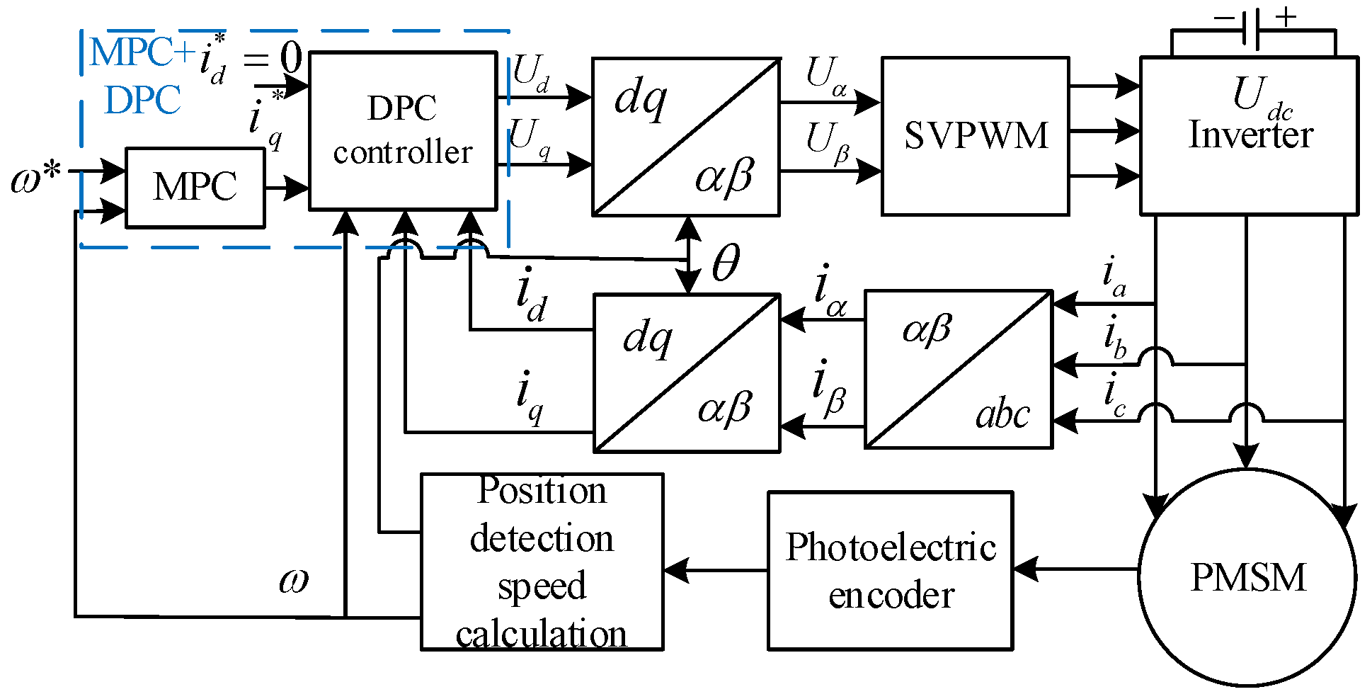
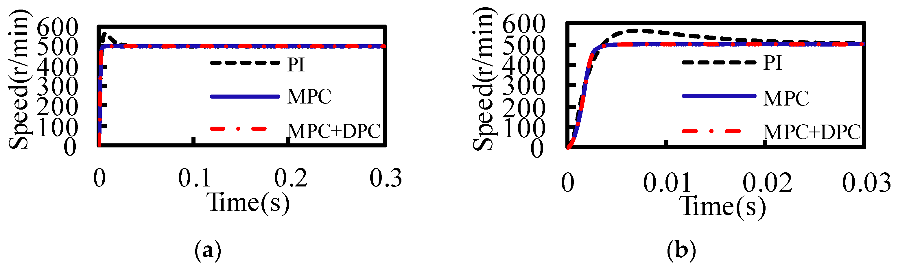
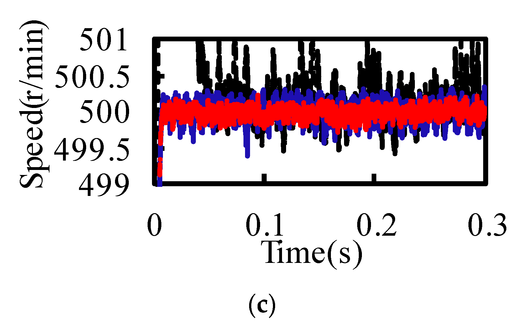
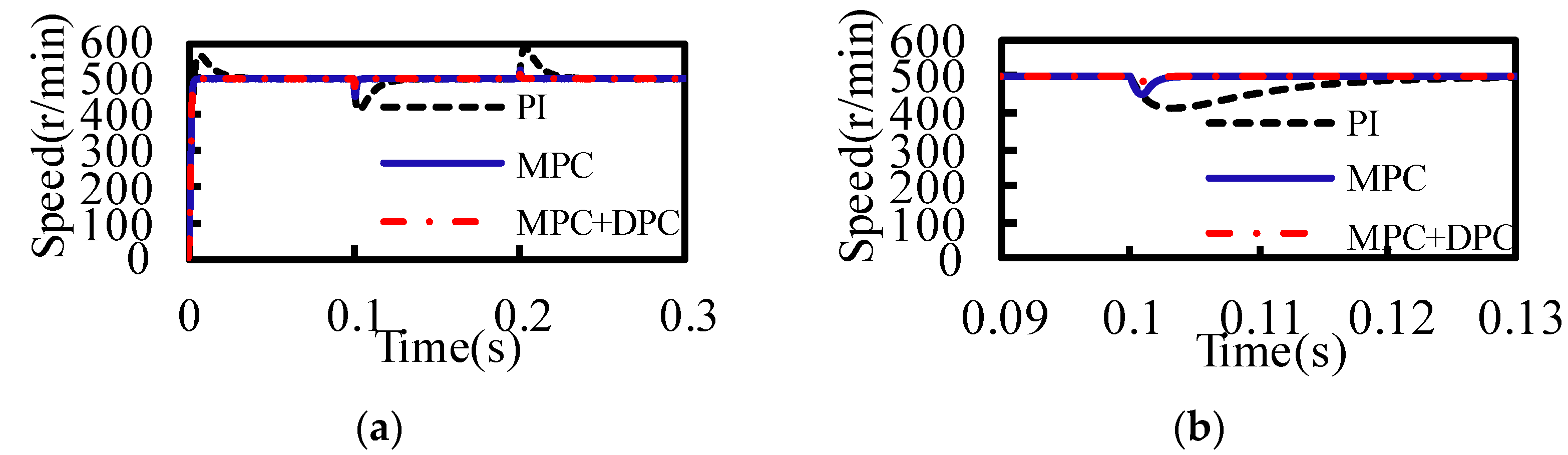
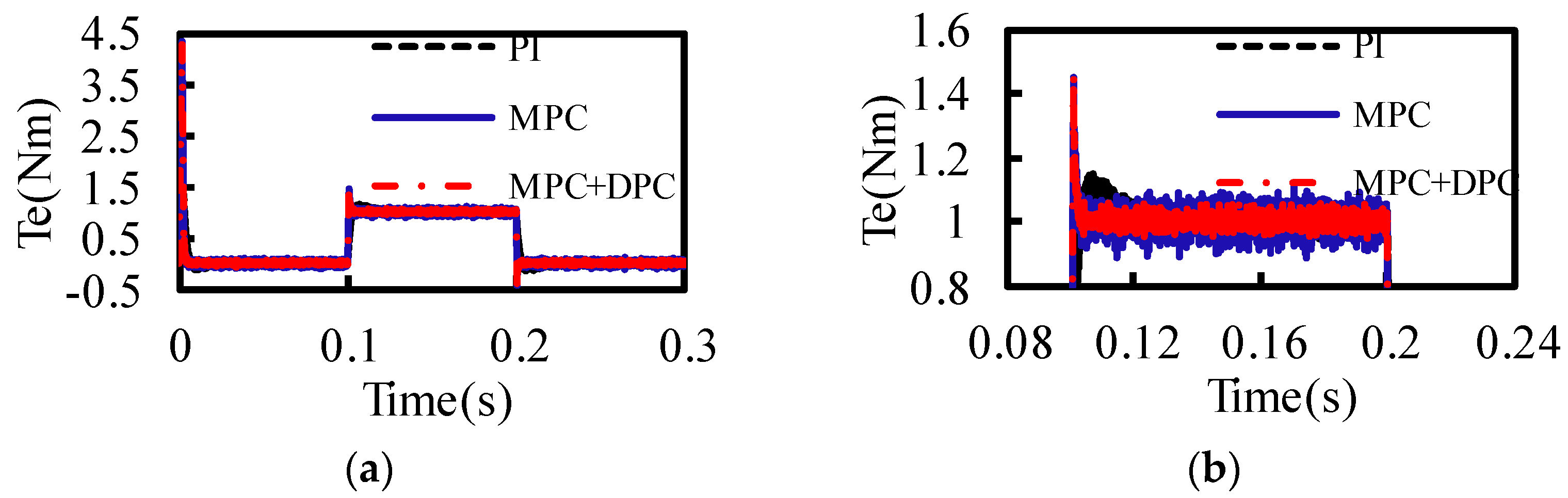
Section 2, based on the mathematical model of PMSM, a speed loop model predictive control (MPC) and a current loop DPC are designed to form a double closed-loop predictive control system. The performance of the three control strategies MPC+DPC, MPC, and PI is compared and verified by a simulation model. Then, the sensitivity of the parameter change of traditional current predictive control is analyzed in
Section 3. In order to improve the anti-parameter disturbance performance of the system, parameter disturbance sliding mode observer (DSMO) and parameter disturbance internal model observer (DIMO) are proposed.
Section 4 is devoted to the experimental verification of proposed predictive control system. Finally, conclusions are drawn in
Section 5.
3. Design of the Disturbance Observer
3.1. Parameter Mismatch Analysis
From the current DPC model, the actual current values
id(k + 1) and
iq(
k + 1) at the next moment under the actual motor parameters can be calculated as follows:
where
L0 is the actual inductance,
R0 is the actual resistance, and
Ψf0 is the actual rotor flux linkage.
Actually, there is a gap between nameplate parameters and actual parameters. The equations under the nameplate parameters can be expressed as
where
Lmod is the nameplate inductance,
Rmod is the nameplate resistance, and
Ψfmod is the nameplate rotor flux linkage.
If the calculated voltage values of Equations (19) and (20) are equal, the error relationship equations between the actual current and the predicted current can be expressed as
where
,
,
.
Since
T is very small, items related to
T can be ignored in Equation (21). Performing Z transformation, one can get
Then, the transfer function between the predicted current value and the actual value can be expressed as
It is obvious that there is a closed-loop pole z = 1 − Lmod/L0 in the closed-loop transfer function. The closed-loop system can remain stable only if the pole is in the unit circle, so 0 < Lmod < 2L0.
When the system is running in a steady-state, assuming
id(
k + 1) =
id(
k) and
iq(
k + 1) =
iq(
k), one can get
When only considering the influence of resistance parameters, combined with the system using
id = 0, one can get
Then, the error of dq-axes currents is less affected by the resistance.
When only considering the influence of inductance parameters, one can get
Although the changes of T and inductance are small, ωe may be very large, so the error of id current is greatly affected by the inductance.
When only considering the influence of rotor flux parameters, one can get
Then, the error of the iq current is proportional to the deviation of the rotor flux linkage and the speed, which is greatly affected by the rotor flux linkage.
In this paper, the influence of the resistor, inductance, and flux parameter mismatch on the static current error is deduced based on the current discrete equation, and the closed-loop transfer function between the predicted and actual current values in the discrete domain is used to obtain that the inductance should meet 0 < Lmod < 2L0 to ensure the stability of the system.
From the above, the parameters mismatch will have a significant impact on the error of dq-axes currents. The disturbance observers are designed to compensate in the paper.
3.2. Design of Disturbing Sliding Mode Observer
The
dq-axes stator voltage equations under actual parameters can be expressed as
When the motor parameters are disturbed, one can get
where
md and
mq are the compensation amounts of the
dq-axes voltage vector when the motor parameters are disturbed,
Md and
Mq are the differentials of
md and
mq, which are close to zero.
Then, the compensation of voltage and the observation of current can be obtained as
where
and are the observed values of the
dq-axes current,
and
are the observed values of the
dq-axes voltage compensation,
Mds and
Mqs are the sliding mode control functions of the
dq-axes,
kd and
kq are the sliding mode coefficients, respectively.
By subtracting Equation (31) from Equation (29) and subtracting Equation (32) from Equation (30), one can get
where
are the difference between the actual values of the
dq-axes current and the observed one,
are the error between the actual values of the
dq-axes compensation voltages and the observed values, respectively.
The sliding mode surface is selected as
. In order to obtain better observation results, the exponential reaching law is chosen to design the sliding mode control function, which can be expressed as
where
and
are both reaching law parameters.
Substituting Equation (35) into Equations (33) and (34), one can get
Since Δ
md and Δ
mq are included in the sliding mode control function, which can be ignored. Then, Equation (36) can be expressed as
In order to converge the disturbance compensation voltage error and current error and ensure the stability of the control system, it is necessary to analyze the stability of the designed sliding mode observer. According to the Lyapunov function, Equation (38) needs to be satisfied to achieve the reachability of the sliding mode surface.
The range of
and
can be expressed as
When Equation (40) is satisfied, the system can reach the sliding mode surface. Then, the errors between the observed and actual values of the
dq-axes currents and the errors between their derivatives can all converge to zero, one can get
Then, Equations (33) and (34) can be simplified as
Solving Equation (42), one can get
When both kd and kq are greater than zero, Δmd and Δmd can approach zero at a steady state. The reasonable selection of the above parameters can ensure the stability of the designed observer.
The sliding mode observer for
dq-axes voltage compensation and current when considering parameter disturbance can be expressed as
Then, the
dq-axes voltage vector can be expressed as
3.3. Design of Disturbing Internal Mode Observer
When the motor parameters are disturbed, the error term can be expressed as
According to Equation (34), the state observation equation can be constructed as
The error variables that define the actual value and the observed value are as follows:
Subtracting Equation (48) from Equation (29), the error state equation can be expressed as
According to the derivation of the first line in Equation (50), a new state equation can be constructed as
where
,
.
Because of , the system is completely controllable. According to the principle of state feedback, state feedback control can be realized. Let , where , kd1 and kd2 are the parameters to be optimized in the observer. Then, there is .
Since the sampling period is very small, it can be assumed that the d-axis disturbance compensation voltage value remains unchanged within a sampling period, which means .
The derivative of the estimated
d-axis disturbance compensation voltage value can be expressed as
Let its characteristic equation
= 0 and one can get
Let the expected poles of the observer be
xd1 and
xd2, then the values of
kd1 and
kd2 can be obtained as
According to Equations (48) and (52), the
d-axis disturbance compensation voltage observer equation can be expressed as
Then, by Laplace transform performing, Equation (55) can be transformed into
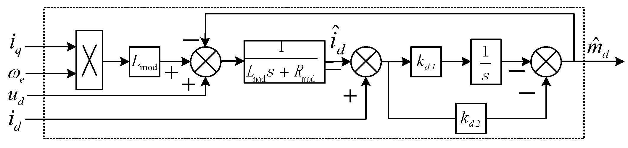
The observer structure can be designed as shown in
Figure 5. It can be seen that the control quantity of the observer is obtained in the form of integration and proportion, and the compensation control effect is excellent.
Assuming that the sampling period
T is small, the differential term can be approximated by difference, so Equation (55) can be discretized, one can obtain
Then, the
d-axis voltage vector can be expressed as
Similar to the construction method of the
d-axis disturbance observer, the
q-axis parameter disturbance compensation voltage observer equation can be obtained as
Then, by Laplace transform performing, (59) can be transformed into
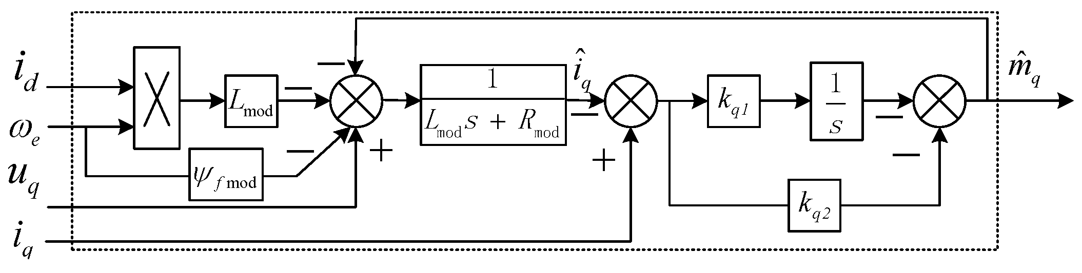
The observer can be designed as shown in
Figure 6.
Assuming that the sampling period
T is small, the differential term can be approximated by difference, so Equation (59) can be discretized, one can get
Then, the
q-axis voltage vector can be expressed as
3.4. Simulation Analysis
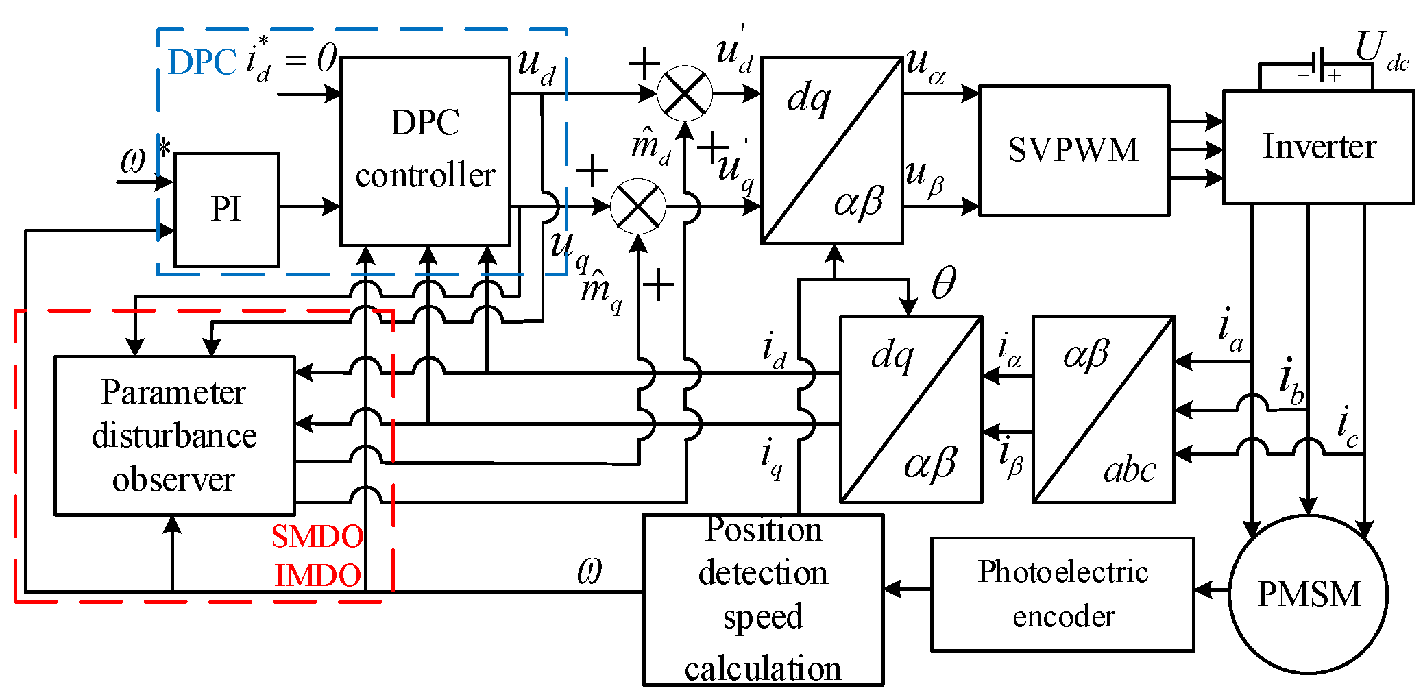
The deadbeat current predictive control system based on parameter disturbance observer is shown in
Figure 7. Simulation models of parameter disturbance sliding mode observer and internal model observer are built to verify whether the proposed parameter disturbance observer can improve the control performance of PMSM under the condition of motor parameter mismatch. From the aspects of resistance mismatch, inductance mismatch, rotor flux mismatch, and various motor parameter mismatch, the performance of predictive control with disturbance observer and traditional predictive control on the static error of
dq-axes currents is compared.
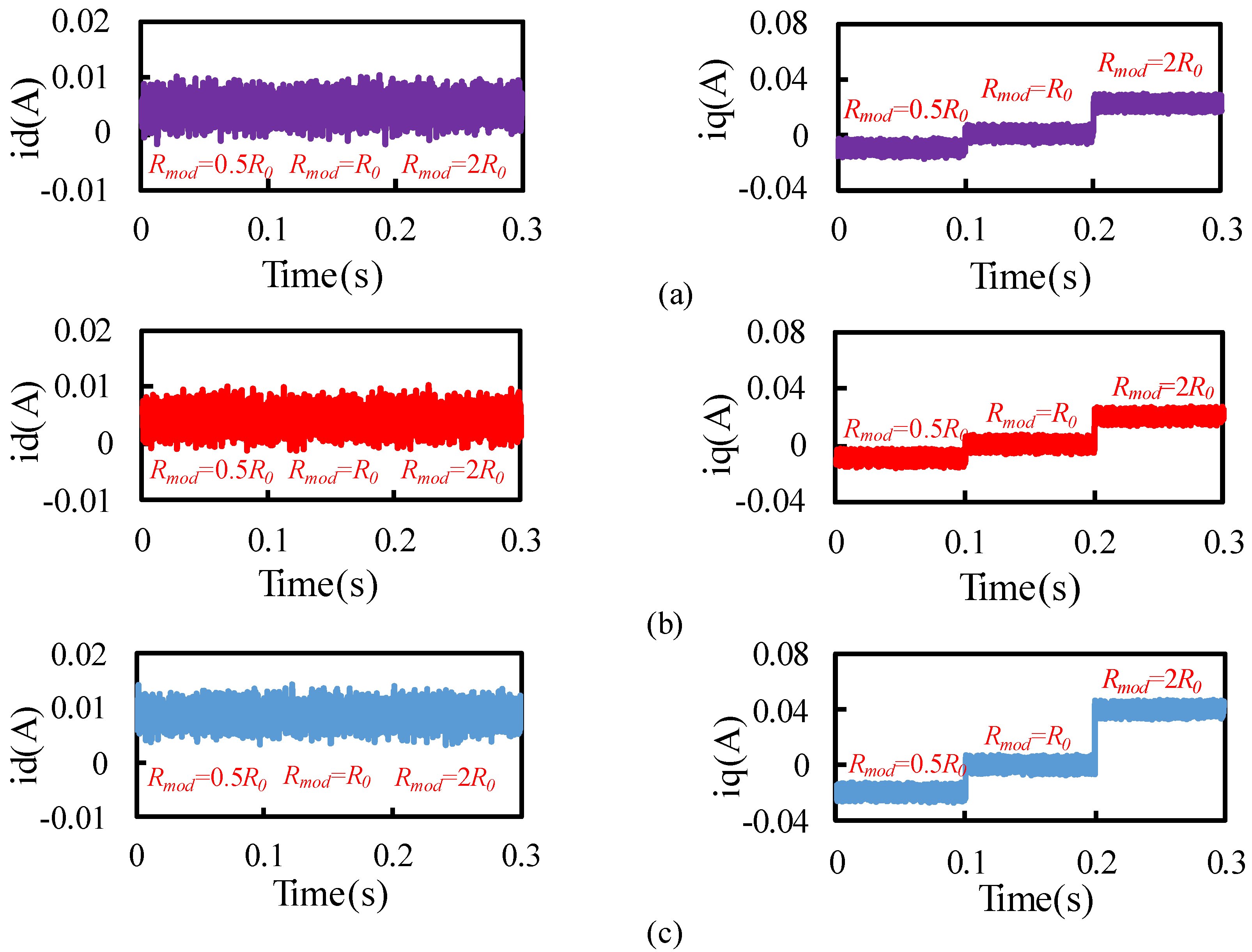
Assuming that the nominal and actual values of the inductance and rotor flux linkage are equal, the error of the
dq-axes currents is affected by the mismatch of motor resistance parameter. The nominal value of the resistance is set to be 0.5, 1, and 2 times of the actual value. The results are shown in
Figure 8. It can be seen that the
id current error is almost not affected by the resistance change. When the nominal resistance and the actual resistance are greater, the
iq current static error is also larger, which is consistent with the theoretical analysis result. After the disturbance observer is added, the static error between
id and
iq currents is significantly reduced.
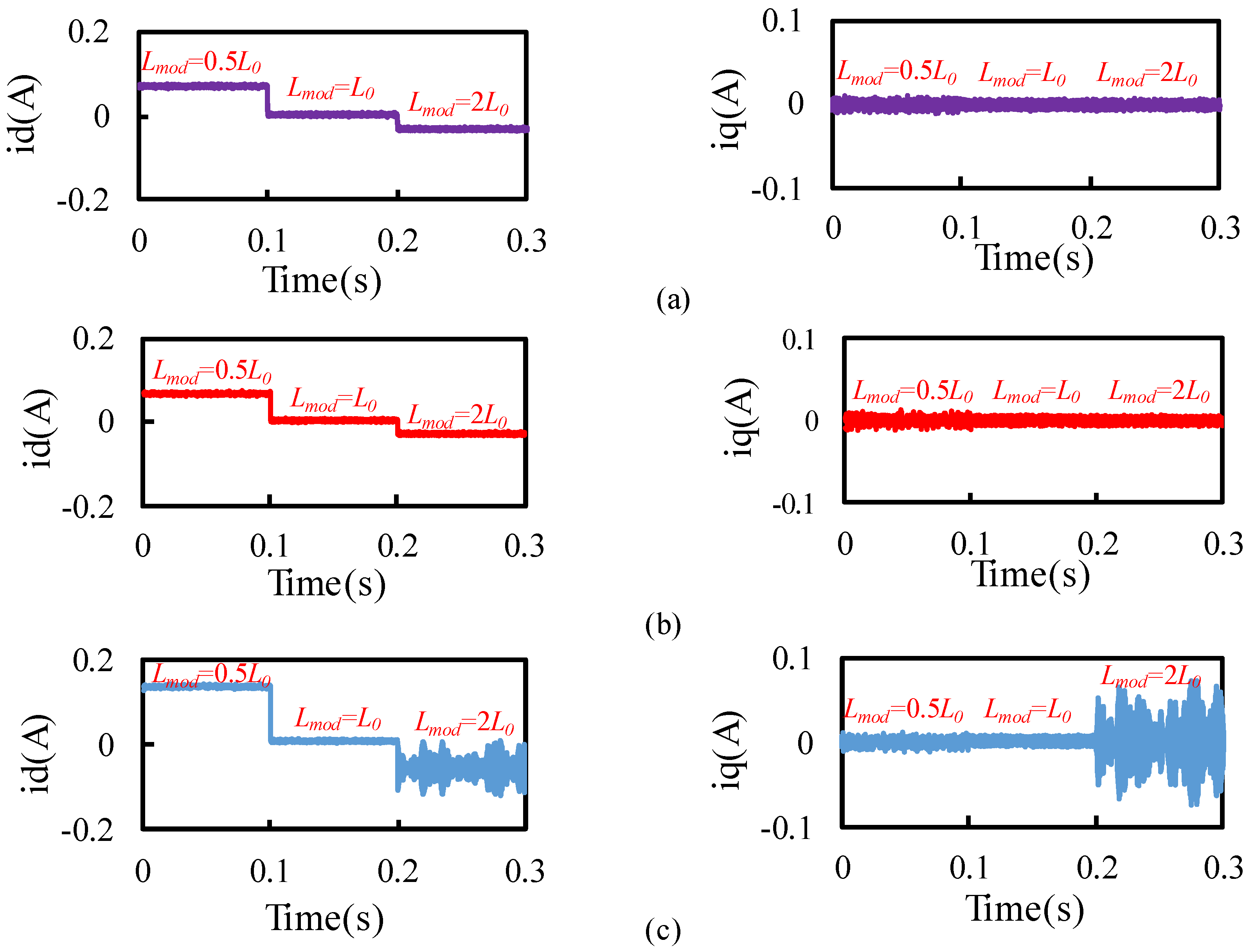
When only considering the error of the
dq-axes currents due to the mismatch of the inductance parameter, the results are shown in
Figure 9. It can be seen that in the stable range, the
id current error is greatly affected by the inductance change, and the
iq current error is almost unaffected, and when the nominal inductance is twice of the actual value, the system begins to be unstable. After adding the disturbance observer, the
id and
iq current errors are significantly reduced, the system is not unstable, and the current error under the internal model disturbance observer is smaller.
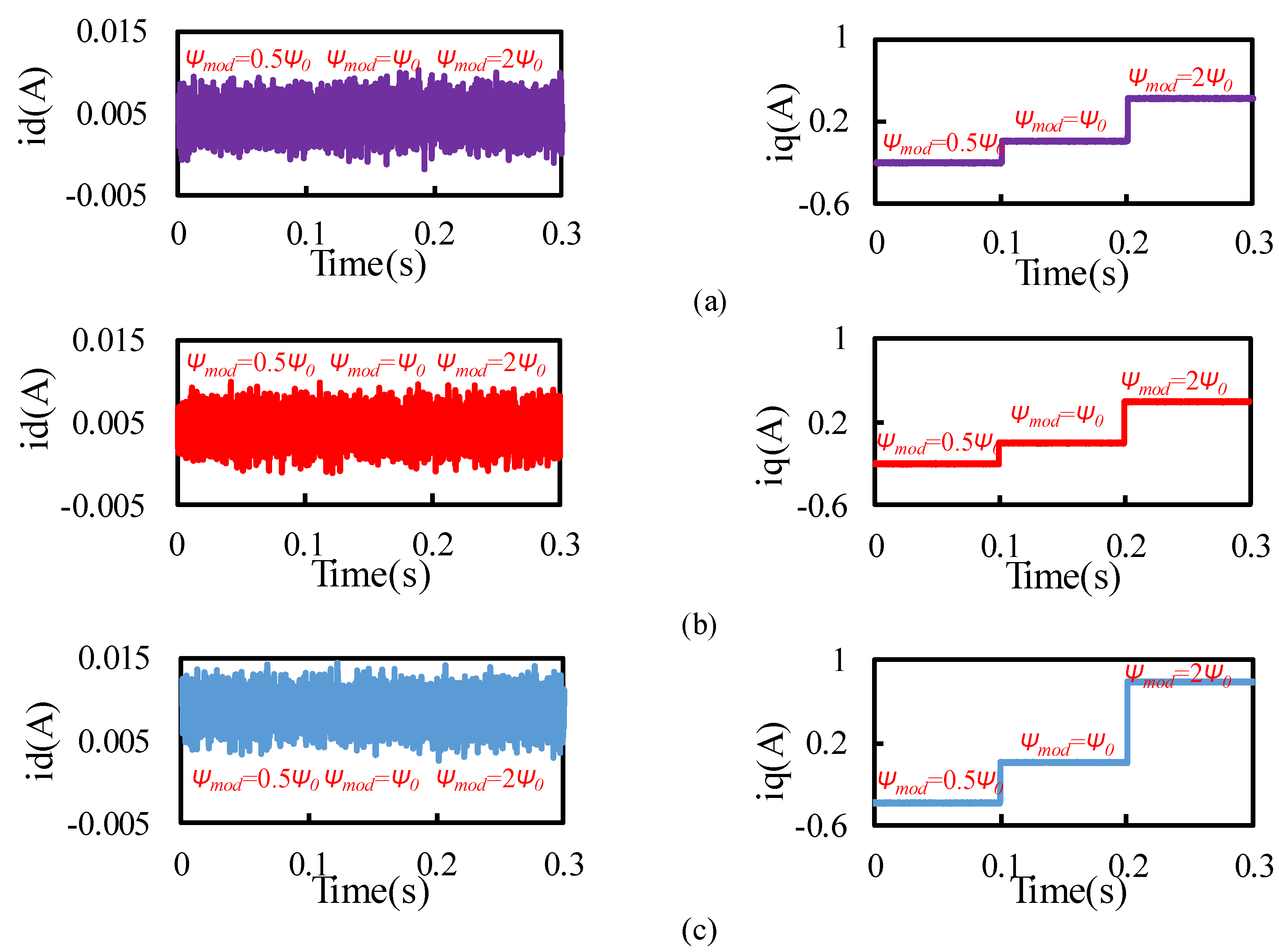
When only considering the error of the
dq-axes currents due to the mismatch of the flux linkage parameter, the results are shown in
Figure 10. It can be seen that the
id current error is almost unaffected by the flux linkage change, and the
iq current static error is greatly affected by the flux linkage change. When the error between the nominal flux linkage value and the actual value is larger, the
iq current error value is also greater. After adding the disturbance observer, the
id and
iq current errors are obviously improved, and the current error under the internal model disturbance observer is smaller.
Figure 8,
Figure 9 and
Figure 10 are summarized in
Table 3, and the current fluctuation range under parameter mismatch is given. It can be seen from the figure and table that the static errors of
dq axes are consistent with the theoretical analysis of
Section 3.1, and the influence of parameters on current static errors can be reduced by adding the observer. In addition, the performance of IMDO is better than that of SMDO.
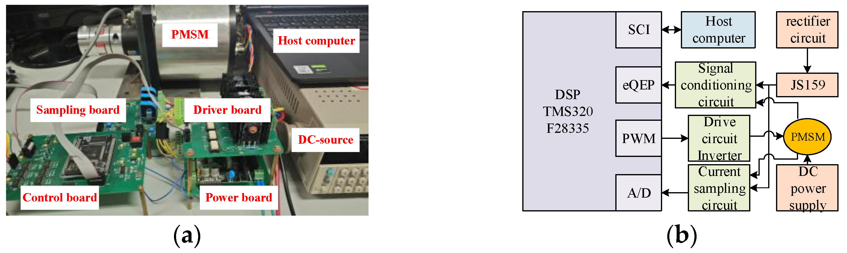
4. Experimental Verification
In order to verify the effectiveness and feasibility of the proposed predictive control system, an experimental platform and the hardware circuit platform are built as shown in
Figure 11, which consist of a microcontroller unit TMS320F28335, some circuits, and some power supplies, etc. The speed servo system experimental control platform is set up, and the DPC controller is compared with the traditional PI controller, the controller parameters of which are manually fine-tuned from the simulated parameters.
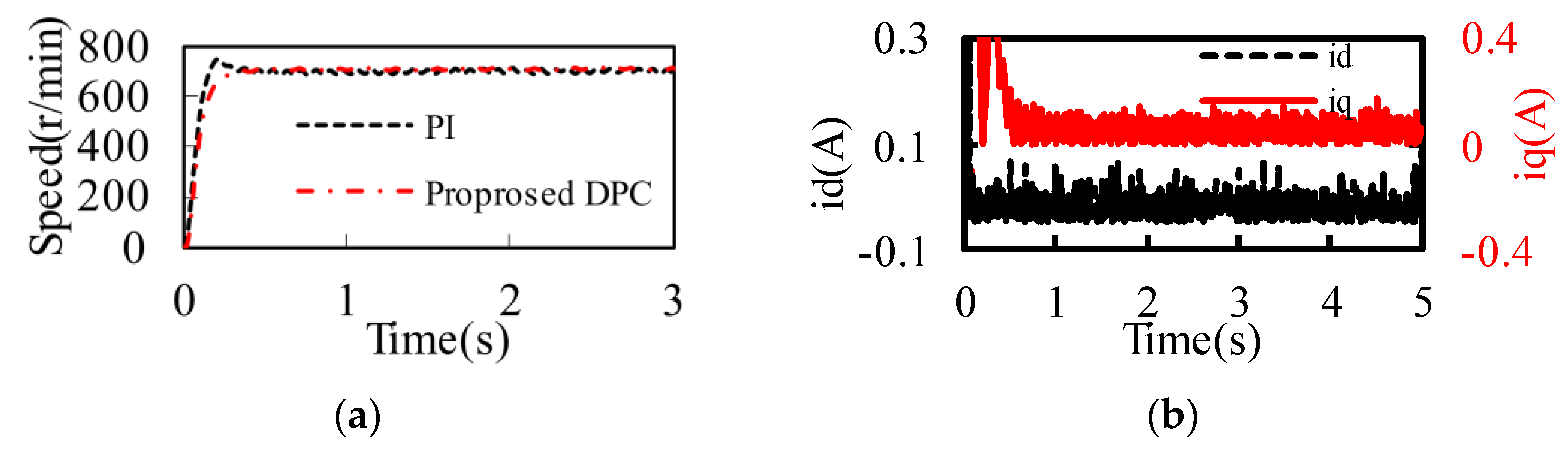
When the given reference speed is 700 r/min,
Figure 12a shows the comparison of the speeds under the two control strategies. It can be seen that, compared with the traditional PI controller, the DPC controller has a faster speed response, the system does not overshoot, and the steady-state speed error is smaller, indicating that the DPC controller has better dynamic and steady-state control performance.
Figure 12b shows the
dq-axes current, and it can be seen that the
iq current will increase temporarily during the motor startup stage, but when the motor is stable, the
iq current almost remains unchanged, indicating that the system has a fast response speed and good dynamic performance.
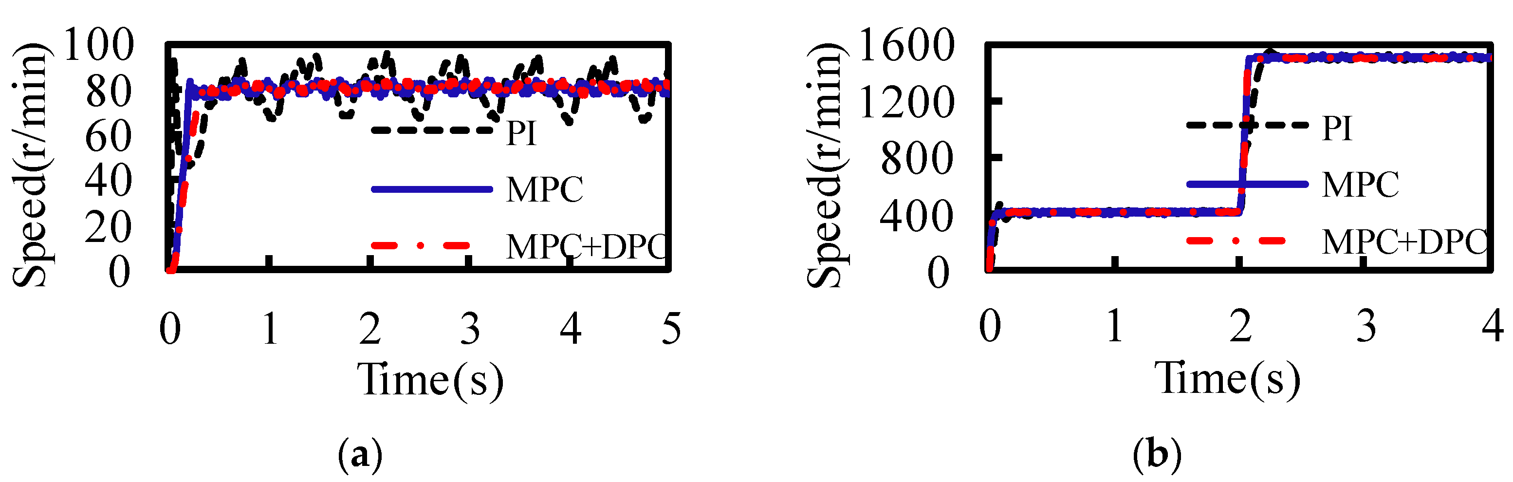
When the given reference speed is 80 r/min, the difference in control performance of the two control algorithms at low speed is considered.
Figure 13a shows the speed comparison under the three control strategies, and the speed fluctuates significantly compared with the previous high-speed conditions, mainly due to the influence of factors such as cogging torque. The PI control has a severe overshoot, initial velocity has reached 90 r/min. However, compared with the PI controller, the overshoot of conventional DPC becomes smaller, and the steady-state error is reduced from ±9 r/min to ±4 r/min. The proposed DPC has almost no overshoot and the steady-state speed error is ±3 r/min, which can effectively reduce the steady-state error, indicating that the proposed DPC controller has better control performance, high control accuracy, and excellent wide speed adjustment capability.
In order to test the speed regulation performance of the control system, the reference speed is set to be initially 400 r/min, suddenly increases to 1500 r/min at 2 s. The comparison response of the speed under the three control algorithms is shown in
Figure 13b. It can be seen that speed can track the given speed under the three control strategies, but compared with the traditional PI controller, the conventional DPC controller has no overshoot of the speed fluctuation and start-up response time is 0.34 s, and the steady-state error is reduced from ±12 r/min to ±9 r/min. Moreover, the proposed MPC in this paper can reduce the speed fluctuation more effectively, the steady-state error is reduced to ±7 r/min, and the speed regulation performance and the robustness are strong.


