Article

Study on the Construction Method and Effects of Ipsilateral, Multi-Nozzle, High-Pressure Jet Grouting Cut-Off Wall

1
Jiangxi Hydraulic Safety Engineering Technology Research Center, Jiangxi Academy of Water Science and Engineering, Nanchang 330029, China
2
State Key Laboratory of Water Resources and Hydropower Engineering Science, Wuhan University, Wuhan 430072, China
*
Authors to whom correspondence should be addressed.
Sustainability 2022, 14(16), 10383; https://doi.org/10.3390/su141610383
Submission received: 13 July 2022 / Revised: 18 August 2022 / Accepted: 18 August 2022 / Published: 20 August 2022
(This article belongs to the Special Issue Civil and Hydraulic Engineering Safety)

Abstract

:
High-pressure jet grouting is widely used in the construction of cut-off wall in hydraulic engineering. Compared to the high-pressure jet grouting used for foundation improvement, the high-pressure jet grouting cut-off wall of hydraulic engineering has lower requirements for the advance consolidation and provision of bearing capacity, and more focus on providing an anti-seepage effect and ensuring the continuous integrity of the wall. In the past, the research on high-pressure jet grouting focused more on the application to foundation treatments, and the research on the construction efficiency of cut-off wall is relatively insufficient. Therefore, in this study, a self-developed ipsilateral multi-nozzle jet grouting machine with a large drill diameter and construction method are proposed according to the construction characteristics of the embankment cut-off wall in hydraulic engineering. Based on the dyke protection projects, Jinggangshan navigation hydropower and Xingan navigation hydropower, the large-diameter, multi-nozzle, high-pressure jet cut-off wall test is carried out, and the wall forming effect of the cut-off wall is verified through the combination of indoor and outdoor tests. The results show that the proposed construction method can adapt to the formation conditions in which it is difficult to implement conventional high-pressure jet grouting, and obtains good construction efficiency. A favorable wall quality can be obtained by using more efficient large-diameter and ipsilateral multi-nozzle jet grouting in the construction of high-pressure jet cut-off wall.

1. Introduction

The high-pressure jet grouting method is widely used in civil and hydraulic engineering [1,2,3]. The basic principle is that water or slurry jets out from the nozzle through the high-pressure pump or high-pressure mud pump, impacting and damaging the soil mass, and filling and mixing it with cement matrix slurry to form a pile, column or plate wall-like condensate, which is used to improve the seepage prevention or bearing capacity of the foundation [4,5]. Compared to other conventional cut-off wall processes, the high-pressure jet grouting cut-off wall equipment is smaller in size and can be applied to narrow operation sites [6,7].
In terms of construction method, unlike high-pressure jet grouting commonly used in pile foundation engineering, high-pressure jet grouting cut-off wall in hydraulic engineering has lower requirements for consolidating foundations and providing bearing capacity, but is more focused on providing a seepage-proof effect and satisfying the continued integrity of the wall [8]. Therefore, high-pressure jet grouting cut-off wall in hydraulic engineering, whether using a rotary jet, swing jet or fixed jet, usually has a small borehole diameter. In addition, because the high-pressure jet grouting cut-off wall in hydraulic engineering is implemented on the embankment, the working face of the top of the embankment is narrow and the high-pressure jet grouting cut-off wall is thin and thick, it is difficult to increase the drilling diameter due to the limitations of past construction machinery and drilling conditions. Since the drilling holes are small, the drill pipe is relatively thin and the rigidity is small, in order to balance the grouting pressure released by the nozzle, the nozzles at the bottom of the nozzle are usually arranged in opposite directions [9]. Therefore, the conventional high-pressure jet grouting method has the problem of low drilling efficiency [10]. Specifically, once the conventional high-pressure jet grouting meets the thicker particles, the nozzle is blocked, which makes it difficult to drill holes and ensure the continuity and integrity of the wall surface, and it is easy to cause the quality defects of local leakage jet grouting [11,12]. At present, in order to improve the ground adaptability of high-pressure jet cut-off wall in hydraulic engineering, mechanical improvement and grout material improvement methods are mostly used [13,14,15,16]. Yuan et al. [17] proposed a new horizontal jet grouting equipment to eliminate the harmful effect on the surrounding environment due to the injection of a large amount of water and/or grout under high jetting pressure. Guo et al. [18,19] studied the feasibility of the application of foamed polyurethane grouting in reservoir dam seepage prevention and achieved good results. Timothy et al. [20] studied the collapse and instability of rotating jets in cut-off wall construction and suggest potential causes of the inclusions. Akin et al. [21] studied statistical relationships between physical and mechanical properties of the soilcrete of grouting methods among various ground improvement techniques. In the past, a large number of studies were conducted from the perspective of process improvement and grouting materials to improve the anti-seepage effect, wall forming quality and stratum adaptability of the high-pressure jet cut-off wall. Few studies were conducted to improve the grouting machinery to improve the construction efficiency of high-pressure jet drilling and grouting.
In terms of the detection and evaluation of the cut-off wall quality in hydraulic engineering, as an underground concealed structure, it has always been a difficult problem to detect and evaluate the wall quality of high-pressure jet grouting cut-off wall [22,23]. However, the quality of the wall plays an important role in the seepage safety and stability of the reinforced dyke [24,25,26]. A borehole coring permeability coefficient test is still the most commonly used testing method to determine permeability [27,28]. However, excavation and core drilling cause man-made damage to the wall, and increasingly less non-destructive testing methods are also used in the detection of wall quality [29,30,31,32]. Modoni et al. [33] analyzed the quality of jet grouting with single-fluid and double-fluid jet grouting, and different grouting components and injection parameters through the indoor test of sample coring. Nikbakhtan et al. [34] presented the amount of principle jet grouting parameters at the foundation of a dam according to the results of a jet grouting test. Fu et al. [35] introduced a new type of on-site non-destructive testing instrument for the impermeability measurement of walls. Zhang et al. [36] studied the feasibility of non-destructive testing of polymer cut-off walls based on vibration theory. In addition, the finite element numerical calculation method is often used to explore and evaluate the relationship between shotcrete materials, shotcrete parameters and wall indicators [37,38,39]. Wang et al. [40] analyzed the watertightness of jet-grouted cut-off walls with geometric imperfections and deduced a simplified theoretical model. Flanagan et al. [41] calculated the in-situ hydraulic conductivities of both the surrounding glacial soils and the jet grout walls by matching observed inflows and piezometric levels. At present, the most reliable methods for the quality inspection of cut-off walls are still excavation detection and borehole coring, while non-destructive detection is an effective supplement.
In this study, based on the improvement and innovation of the equipment of the conventional high-pressure jet grouting cut-off wall in hydraulic engineering, the construction machinery and method of large-diameter, ipsilateral multi-nozzle cut-off wall is proposed, and the working principle of the construction machinery and method of large diameter, ipsilateral multi-nozzle cut-off wall is analyzed. Through a field construction test, the construction effectiveness and wall quality reliability of large-diameter, ipsilateral, multi-nozzle high-pressure jet grouting cut-off wall are verified.

2. Construction Method and Process

2.1. Device Characteristics

The nozzles at the bottom of the jet bar of the conventional high-pressure jetting method are usually arranged in opposite directions. The advantage of this arrangement is that it can balance the jetting pressure released by the nozzle without offsetting the direction of the nozzle. The disadvantage of this arrangement is that, compared with the centralized arrangement, the jetting pressure is reduced, resulting in the reduction of the efficiency of cutting the formation, as shown in Figure 1. In fact, the high-pressure jet method is an earlier construction technology. With the application of high-strength, large-diameter drilling equipment and multiple-nozzle jet rods, both the pilot hole high-pressure jet and the drilling jet-integrated high-pressure jet grouting can realize the formation cutting with ipsilateral multiple nozzles.
Therefore, through equipment transformation and development, the integrated larger-diameter drill bit and jet design is used for high-pressure jet grouting cut-off wall construction, as shown in Figure 2. Moreover, the high-pressure jet nozzle is set to only jet in one direction, and two or more nozzles are arranged on one side, which can form a more powerful cluster jet than a single nozzle, which is conducive to the fragmentation and deformation of soil when it is cut, and is also conducive to improving the cutting efficiency of high-pressure fluid; in addition, the wall thickness can be controlled by the horizontal spacing and orientation between nozzles. The drilling equipment of ipsilateral, multi-nozzle, high-pressure jet cut-off wall is shown in Figure 3.

2.2. Construction Procedure

The main construction process of the large-diameter, ipsilateral, multi-nozzle, high-pressure jet grouting cut-off wall is as follows:
(1)
Preparation before construction
The production power supply is arranged, and grid power is preferred. For projects without grid power conditions nearby, diesel generator sets with a rated power of more than 300 kW are used. Arrange water pumps and water pipelines between the water source and the water storage tank. Build construction access roads to meet the requirements of access roads for equipment and materials. A strip-shaped site is leveled along the construction axis of the cut-off wall, the obstacles at the construction axis are removed, and the low-lying parts of the site are backfilled with clay for leveling.
(2)
Wall axis measurement and setting out
Mark the axis of the cut-off wall, set up an axis control pile at intervals, calibrate the position of the pile number, and make records and maintenance.
(3)
Excavation of slurry guide groove
Excavate the slurry guide groove along the axis of the cut-off wall. In order to prevent slurry overflow, the groove depth should be greater than 1 m, and the groove width should be greater than 1.2 times the drill bit diameter.
(4)
Hole location setting out
The hole location setting out is carried out according to the design hole spacing. It should be noted that, in order to ensure the accurate positioning during drilling, marks should be set along both sides of the slurry guide slot, and hole location marks should also be made on both sides away from the slurry guide slot (the outer edge of the rig leg).
(5)
Layout of backstage pulping system
Find an open site near the construction section to lay the pulping system, and fully consider factors such as the access of raw materials, the convenience of power and water supply, and the radiation range of pulp pipes.
(6)
High-pressure fluid pipeline connection
The high-pressure slurry pipe and high-pressure gas pipe are used to connect the high-pressure pump and air compressor with the high-pressure jet drilling rig.
(7)
Slurry preparation
Prepare and mix cement slurry (the water–cement ratio is generally 1:1, which can also be designed according to the specific situation of the project). The material consumption of each mixing drum is calculated according to the mix proportion and the volume of the mixing drum. During pulping, water is discharged to the calculated dosage per barrel, and then cement is added. Each barrel is stirred for not less than 2 min. The slurry is prepared and used at any time. In order to prevent the segregation of cement slurry, it must be stirred continuously, and the mixed slurry is transported to the secondary-mixing slurry storage container at the same time.
(8)
Drill hole
The high-pressure jet drill is used for drilling, and the diameter of the drilling hole can be determined according to the design wall thickness. High-pressure jetting cannot be carried out during drilling, that is, inject low-pressure water (or cement slurry) and low-pressure air until it enters more than 50 cm into the bedrock. The judgment standard for entering the rock is made according to the results of the pilot hole, as well as the working current, sound, vibration and other conditions of the drilling rig. and Make a record of the drilling depth according to the scale on the drilling tower.
(9)
Slurry transportation, gas transportation, static injection and lift injection
Adjust the drill pipe so that the nozzle faces the direction of the previous drilling, pause the rotation of the drill pipe, jet high-pressure cement slurry from the nozzle on the side of the drill bit, and then lift the jet rod to mix the cement slurry fully with the formation materials after breaking the formation.
(10)
Lift the nozzle to the design elevation, stop jetting, and move it to the next hole.
(11)
Consolidate into a wall
Repeat the above steps, in a hole-by-hole cycle, to form a continuous and complete high-pressure jet grouting cut-off wall.
The main difference between the construction procedure of the large-diameter, ipsilateral, multi-nozzle jet grouting cut-off wall and the conventional high-pressure jet grouting cut-off wall is that, firstly, the conventional method usually requires the use of drilling equipment to drill the guide hole in advance, and then jet the slurry through the grouting trolley. However, the construction of the large-diameter, ipsilateral, multi-nozzle, high-pressure jet grouting cut-off wall proposed in this study adopts an integrated drilling and spraying equipment (the nozzle and high-pressure pipeline are embedded into the large-diameter drill). The same equipment can be used for drilling and jet grouting. There is no need to drill pilot holes in advance. The diameter and efficiency of drilling are far greater than those of conventional methods. Secondly, because the nozzle is more concentrated, it can be controlled in the construction of the fixed-jet method, and the nozzle can be controlled to jet in the direction of forward drilling, so that the shotcrete pressure acts on the loosened stratum, which is conducive to the crushing and mixing of rock and soil mass.

3. Quality Inspection Method of Cut-Off Wall

3.1. Water Permeability Test

Core samples are drilled and maintained in the cut-off wall until the specified test age. After removing and drying the surface, a layer of sealing material (e.g., silicone rubber) is applied to the side of the sample and the inner surface of the test model. The core sample is pressed into the test model to make both bottom surfaces level. After 24 h of rest, it is loaded into an SS-2.5 permeameter to conduct a water permeability test, as shown in Figure 4. The water pressure increases until all the top surfaces of the specimens are watertight. Water pressure and corresponding constant pressure time t for each pressure section of each sample are recorded.
The impermeability coefficient of mortar specimens is calculated according to Formula (1), and the average value of the measured values of the specimens is taken as the test result of the impermeability coefficient of this group of core samples.
I = P i t i
where I is the impermeability coefficient of mortar samples, MPa·h, P t is the water pressure of the test sample at each pressure stage, MPa, and t i is the constant pressure time of corresponding pressure stage, h.
The relative permeability coefficient of the concrete of the test piece is in accordance with Formula (2)
K r = α D m 2 2 t H
where K r is the relative permeability coefficient, cm/h, D m is the average water penetration height, cm, H is the water pressure, expressed in water column height, cm, and α is water absorption of concrete.

3.2. High-Density Electrical Method

Based on the conductivity difference of geotechnical media, the high-density electrical method observes and studies the distribution law of the current field to detect underground geological problems. In order to further verify the wall-forming quality of the large-diameter, ipsilateral, multi-nozzle, high-pressure jet cut-off wall, relying on the flood control project of Jinggangshan navigation hydropower, the parallel high-density electrical method detection technology is used to detect the permeability of the cut-off wall. The data acquisition method of the parallel electrical method adopts a pseudo-seismic acquisition method, which adopts two methods of monopole power supply (AM method) and dipole power supply (ABM method) for data acquisition and processing. In order to measure the resistivity of uniform earth, symmetrical quadrupole devices are usually arranged on the earth surface, that is, two power supply electrodes A and B, and two measuring electrodes M and N. When the current I is sent underground through the power supply electrodes A and B stable electric field is established in the uniform half space with underground resistivity, and the potential difference is observed at M and N. The calculation expression of the uniform earth resistivity is:
ρ = 2 π 1 A M 1 B M 1 A N + 1 B N Δ U M N I = K Δ U M N I
where A M , B M , A N and B N are the mutual position distances of power supply electrodes A and B that measure electrodes M and N, respectively, Δ U M N is the magnitude of potential difference observed at M and N, and I is the current.
During the field test, the parallel high-density electrical method detection technology is used to collect the background value before water injection on one side of the cut-off wall, then holes are drilled on the other side of the wall, and salt water is injected into the holes to fully penetrate the wall with the salt water. If there are hidden engineering dangers such as leakage in the cut-off wall, the salt water leaks to the opposite side through the hidden dangers, resulting in the reduction of the resistivity value of the corresponding position. At this time, a group or multiple groups of resistivity profile data at different time periods are collected, the resistivity profile after water injection is compared with the background resistivity profile, and the change amplitude of the resistivity value is amplified by ratio processing. The calculation formula of ratio processing is shown in Formula (4), and the place with a large ratio change is determined as the location of hidden leakage danger. The site layout is shown in Figure 5.
η = ρ B ρ S ρ B × 100 %
where ρ B is the background resistivity, and ρ S is the apparent resistivity.

4. Quality Inspection in Jinggangshan Navigation Hydropower Project

4.1. Project Overview

The Jinggangshan navigation hydropower project is located in the middle reaches of Ganjiang River and Ji’an City, Jiangxi Province. The right bank of the dam site is located in Yaotou Town, Wan’an County, and the left bank is located at the junction of Shaokou Township, Wan’an County and Mashi Town, Taihe County. It is a large-scale shipping hydro-electric power project, which focuses on shipping and has comprehensive utilization benefits such as power generation. The total investment of the project is about CNY 4.56 billion. The normal pool level of the hydroproject is 67.5 m, and the storage capacity is 292.8 million cubic meters. The main construction contents include: ship lock, sluice gate, power station, fishway, dam, dam crest highway bridge, reservoir dyke protection works and corresponding supporting facilities. Among them, the focus of the flood control project is the cut-off wall works.
Considering the narrow working face of embankment and the serious borehole collapse in the soil layer, conventional construction machinery for cut-off wall is inefficient. The proposed large-diameter, ipsilateral, multi-nozzle, high-pressure jet cut-off wall in this study was adopted by engineering construction quarters and carried out on the site of the left bank (Xiaping–Yangping embankment section) of the flood control project of the Jinggangshan navigation hydropower project. As shown in Figure 6, the influence of the large-diameter and multiple nozzles on the wall-forming effect of the high-pressure jet cut-off wall was observed.

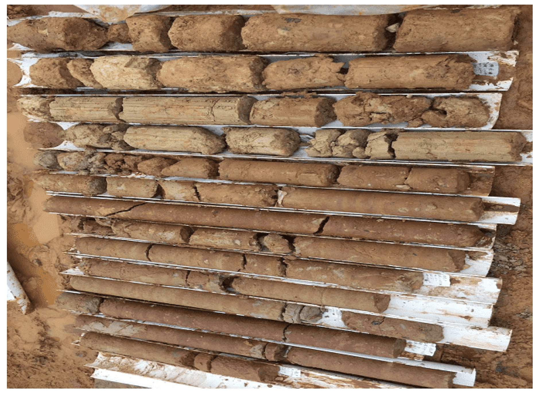
4.2. Wall Body Inspection Test

The drilling and coring method is one of the most commonly used methods to detect the permeability of cut-off walls. 28 days after the completion of construction, one hole is sampled every 500 m along the wall axis, and a drill is used to drill core samples in the wall to describe the continuity and integrity of the core samples and the height of the wall. One group of core samples is selected for each hole, and the holes are sealed with cement mortar after the drilling is completed. The core drilling samples of the test wall are shown in Figure 7, and the impermeability test results of the core samples are shown in Table 1.
In Figure 7 and Table 1. Most of the drilled core samples are long columns, with smooth sides and good cementation. Two groups of core samples are used, and the average permeability coefficient is 6.92 × 10⁻⁷ cm/s, 7.35 × 10⁻⁷ cm/s, respectively, all less than the impermeability design value i × 10−6 cm/s (i = 1~9). It can be seen that, through the transformation of equipment, the application of an integrated larger-diameter drill bit and ipsilateral multi-jet nozzle design can adapt to the difficult construction of conventional high-pressure jet grouting cut-off wall and obtain a favorable permeability coefficient, as well as good construction efficiency.

4.3. Detection of Wall Permeability

The parallel high-density electrical method is used for data acquisition on site. The electrode spacing is set at 1 m, a total of 56 electrodes are arranged, and the length of the measuring line is controlled to be 55 m, that is, the measuring line is extended by 11 m to both ends of the wall to ensure the coverage of electrical data and increase the detection accuracy. The power supply voltage is set to 96 V, the data acquisition method is the AM method, the power supply cycle is 0.5 s, and the sampling interval is 50 ms. Four groups of data were measured, including background data and data at different times after injection of salt water. The data at different times after injection of salt water were 1 h, 2 h, 3 h and 4 h after injection, as shown in Figure 8.
Since sodium chloride solution is used as the missing agent, its resistivity is many times that of clean water. If there is a wall quality problem, the resistivity of the detection part increases significantly. If the resistivity of the tested part does not increase significantly, it indicates that the anti-seepage performance of the wall is good. From the background apparent resistivity profile before water injection, it can be seen that the resistivity value of the geological body under the geodetic line of this test site is mainly distributed at 0 Ω·m to 840 Ω·m, with the passage of time, i.e., 1 h to 5 h after water injection. After water injection for 1 h, the resistivity change rate appeared slightly high in the local part of the wall. With the increase of time after water injection, the resistivity change rate did not expand, but tended to a stable and small value. After water injection for 3 h and 5 h, the vertical downward high resistivity change rate appears at the wall top, which may be caused by the water inflow from the surface of the original borehole, but in general, the resistivity value observed from the magnitude in the contour of the apparent resistivity change rate is stable at 0 Ω·m to 840 Ω·m, and the change rate of resistivity is less than 5%, which means that the apparent resistivity value remains basically unchanged before and after water injection. Sodium chloride from one side of injection does not penetrate to the other side, i.e., there is no obvious leakage in the cut-off wall, and the continuity and integrity of the wall is favorable.

5. Quality Inspection in Xingan Navigation Hydropower Project

5.1. Project Overview

The Xingan navigation hydropower project is located in the middle and lower reaches of Ganjiang River and about 1.5 km from the upper reaches of Sanhu Town, Xingan County, Ji’an City. It is a navigation and power generation-oriented navigation and hydropower project with comprehensive benefits. The size of the lock is 230 × 23 × 3.5 m3 (length × wide × depth), the one-way passing capacity of the lock is 8.21 million tons, and the channel dimensions are 60 m wide, 2.2 m deep, with a 480 m turning radius. The reservoir dyke protection mainly includes the embankment protection on both banks of the main stream, the dyke protection of three major tributaries (Luan River tributary, Meixiang River tributary and Yi River tributary) and the dyke protection of Yingzhou island. The reservoir dyke protection project is divided into 11 protection areas. The total length of the protective embankment in the reservoir area is about 94.25 km, and the total area of field lifting is 8741 mu. Among them, the focus of the flood control project is the cut-off wall works. The proposed large-diameter, ipsilateral, multi-nozzle, high-pressure jet cut-off wall in this study was carried out on the site of the 15# section of the Meixiang River tributary, and the influence of the large-diameter and multiple nozzles on the wall-forming effect of the high-pressure jet cut-off wall was observed.

5.2. Detection of Wall Permeability

The parallel high-density electrical method is used for data acquisition on site. The electrode spacing of the parallel high-density electrical method is 2 m, and a total of 48 electrodes are arranged, totaling 94 m, of which the power supply voltage is 96 V. The data acquisition method is the AM method, the power supply cycle is 0.5 s, and the sampling interval is 50 ms. Two groups of data are measured, which are background data and data after water injection. The time interval between the two data acquisitions is 3 h. Generally, the area where the resistivity change value is greater than 15% is judged to have salt water infiltration in the area, and the corresponding cut-off wall may have hidden dangers such as non-compactness or cavities. Figure 9 shows the resistivity analysis results of four test sections, in which each test section is, respectively, from top to bottom: background resistivity profile, resistivity profile after water injection and resistivity change value profile results before and after water injection.
It can be seen in Figure 9 that, according to the parallel electrical method detection results of the four test wall sections, i.e., stake No. 0 + 685~0 + 735, 0 + 405~0 + 455, 1 + 815~1 + 865, 2 + 255~2 + 305, the difference between the background resistivity and the resistivity profile after water injection is small, and the resistivity change rate is basically in the white and gray range, although the resistivity values of each test stake number wall section obtained by the construction method of large-diameter, ipsilateral, multi-nozzle, high-pressure jet cut-off wall are slightly different before and after sodium chloride injection. The change rate of resistivity before and after water injection is small, generally less than 5%, indicating that the brine on one side of injection does not penetrate to the other side, no obvious leakage area is found within the detection range, and the wall integrity is favorable.

6. Conclusions

In this study, aimed at self-developed mechanical wall building with a large-diameter, ipsilateral, multi-nozzle, high-pressure jet grouting wall, the wall-forming effect is verified. Based on the Xiaping–Yangping embankment section of the dyke protection project in the Jinggangshan navigation hydropower project and the 15# section of the Meixiang River tributary in the Xingan navigation hydropower project, the indoor and field tests of ipsilateral, multi-nozzle, high-pressure jet grouting wall is carried out. The following conclusions can be drawn:
(1)
According to the construction characteristics of the embankment cut-off wall in hydraulic engineering, this study presents the transformation of the conventional high-pressure jet grouting machine, puts forward high-pressure jet grouting with a large-borehole-diameter, ipsilateral multi-nozzle, and puts forward the corresponding construction process based on this. The proposed construction method can adapt to the formation conditions in which it is difficult to implement conventional high-pressure jet grouting, and obtain good construction efficiency.
(2)
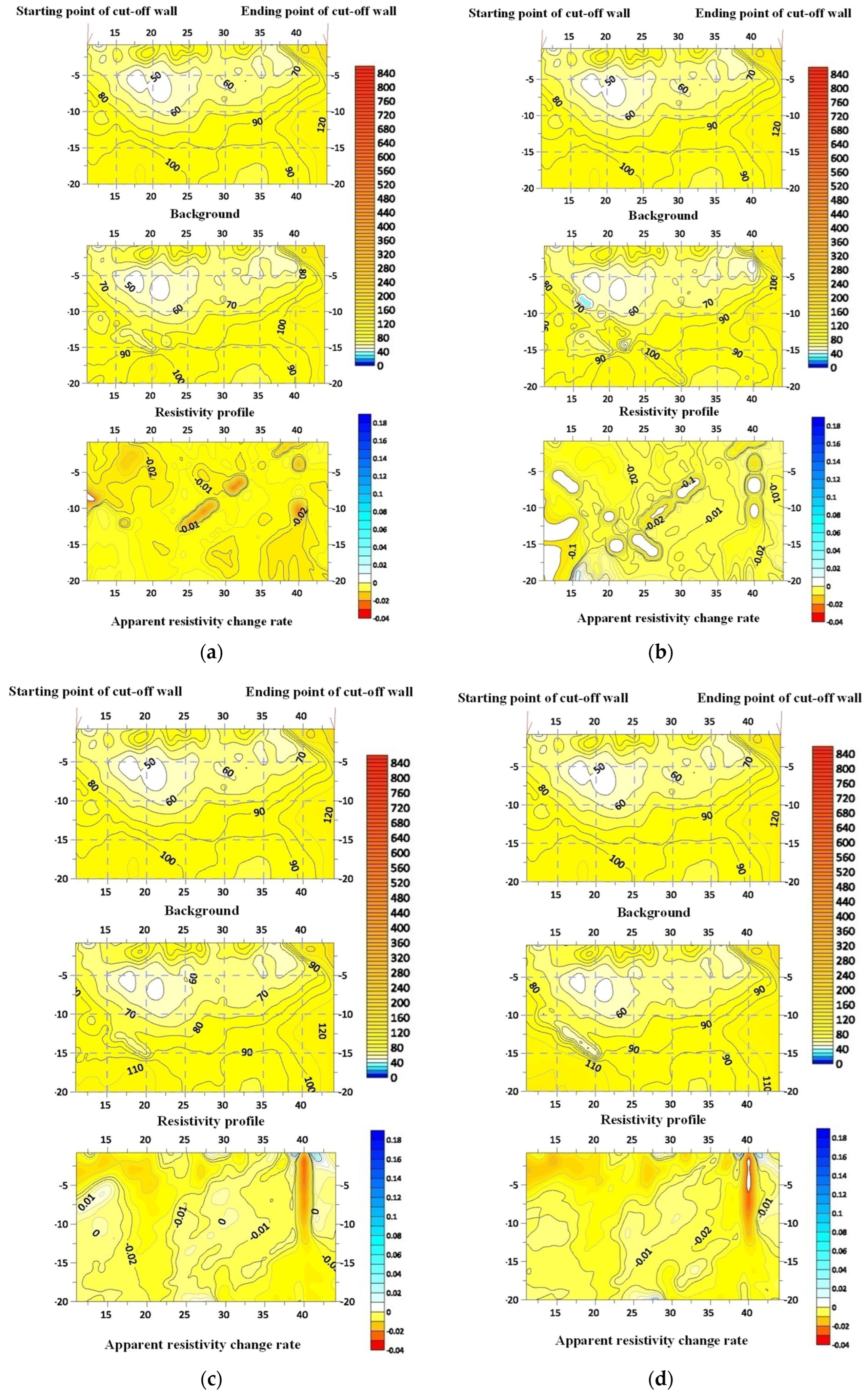
The construction method of high-pressure jet grouting with a large drill diameter and ipsilateral multi-nozzle is adopted to carry out field construction tests and for application in the cut-off wall of the reservoir area dyke protection works of the Jinggangshan navigation hydropower project and Xingan navigation hydropower project. Through penetration tests of core samples from a test wall, the side of core samples is smooth and the bonding is good, and the average permeability coefficient is less than the design value of impermeability. The permeability of the test wall section is detected by a high-density electrical meter, and there is no obvious leakage area in the wall. It indicates that a favorable wall quality can be obtained by using more efficient large-diameter and ipsilateral multi-nozzle jet grouting in the construction of high-pressure jet cut-off wall.

Author Contributions

Conceptualization, D.L. and W.X.; Data curation, W.X., S.H. and Y.L.; Funding acquisition, D.L. and M.C.; Investigation, J.G.; Methodology, J.G.; Software, L.L.; Writing—original draft, D.L. All authors have read and agreed to the published version of the manuscript.

Funding

This work is supported by the Jiangxi Provincial Natural Science Foundation (20212BAB214044, 20203BBGL73234), by the Jiangxi Provincial Department of water resources Foundation (202224ZDKT08) and by the National Natural Science Foundation of China (51779190, 51779193).

Institutional Review Board Statement

Institutional review board approval. Studies not involving humans or animals.

Informed Consent Statement

Informed consent was obtained from all subjects involved in the study.

Data Availability Statement

The data presented in this study are available on request from the corresponding author. The data are not publicly available due to privacy restrictions.

Acknowledgments

The authors wish to express their thanks to all supporters.

Conflicts of Interest

The authors declare no conflict of interest.

References

  1. Shepherd, D.A.; Kotan, E.; Dehn, F. Plastic concrete for cut-off walls: A review. Constr. Build. Mater. 2020, 255, 119248. [Google Scholar] [CrossRef]
  2. Cao, C.; Shi, C.; Lei, M.A. Simplified Approach to Design Jet-Grouted Bottom Sealing Barriers for Deep Excavations in Deep Aquifers. Appl. Sci. 2019, 9, 2307. [Google Scholar] [CrossRef] [Green Version]
  3. Zhang, Q.; Li, L.; Mo, Y. Grouting Technique Applications during Housing Construction. Appl. Mech. Mater. 2015, 724, 53–56. [Google Scholar] [CrossRef]
  4. Pelizza, S.; Peila, D. Soil and rock reinforcements in tunnelling. Tunn. Undergr. Space Technol. 1993, 8, 357–372. [Google Scholar] [CrossRef]
  5. Wu, Y.; Shen, S.; Yin, Z.; Xu, Y.-S. Characteristics of groundwater seepage with cut-off wall in gravel aquifer. II: Numerical analysis. Can. Geotech. J. 2015, 52, 1539–1549. [Google Scholar] [CrossRef]
  6. Manne, A.; Prasad, P.; Annam, M.K. Application of Jet Grouting for Geotechnical Challenges; Springer: Singapore, 2020. [Google Scholar]
  7. Barbu, C.; Sabău, A.-D.; Manoli, D.-M.; Șerbulea, M.-S. Water/Cement/Bentonite Ratio Selection Method for Artificial Groundwater Barriers Made of Cutoff Walls. Water 2022, 14, 376. [Google Scholar] [CrossRef]
  8. Bestuzheva, A.S.; Anakhaev, K.K. Seepage through a Homogeneous Earth-Fill Dam with a Cut-Off Wall on a Permeable Foundation. Power Technol. Eng. 2020, 54, 147–153. [Google Scholar] [CrossRef]
  9. Coomber, D.B. Groundwater control by jet grouting. Geol. Soc. Lond. Eng. Geol. Spec. Publ. 1986, 3, 445–454. [Google Scholar] [CrossRef]
  10. Dai, W.; Liang, L.; Zhang, B. Firefly Optimization Algorithm for the Prediction of Uplift due to High-Pressure Jet Grouting. Adv. Civ. Eng. 2020, 2020, 8833784. [Google Scholar] [CrossRef]
  11. Njock, P.G.A.; Chen, J.; Modoni, G.; Arulrajahl, A. A review of jet grouting practice and development. Arab. J. Geosci. 2018, 11, 459. [Google Scholar] [CrossRef]
  12. Li, Z.; Lv, J.; Xie, X.; Fu, H.; Huang, J.; Li, Z. Mechanical Characteristics of Structures and Ground Deformation Caused by Shield Tunneling Under-Passing Highways in Complex Geological Conditions Based on the MJS Method. Appl. Sci. 2021, 11, 9323. [Google Scholar] [CrossRef]
  13. Dai, G.; Sheng, Y.; Pan, Y.; Shi, G.; Li, S. Application of a Bentonite Slurry Modified by Polyvinyl Alcohol in the Cutoff of a Landfill. Adv. Civ. Eng. 2020, 2020, 7409520. [Google Scholar] [CrossRef]
  14. Fan, R.; Yang, Y.; Liu, S. Impact of In Situ Soil in Soil-Bentonite Cutoff Wall Backfill on Compressibility and Hydraulic Conductivity. Adv. Civ. Eng. 2021, 2021, 9350604. [Google Scholar] [CrossRef]
  15. Dai, G.; Zhang, Z.; Shi, G.; Li, S.; Shi, W.; Li, X. Study on anti-seepage slurry of landfill site modified by sodium carboxymethyl cellulose. Int. J. Mod. Phys. B 2019, 33, 1950377. [Google Scholar] [CrossRef]
  16. Fang, H.; Zhang, H.; Xue, B.; Gao, J.; Li, Y.; Gao, X.; Tian, A. Coordination Characteristics Analysis of Deformation between Polymer Anti-Seepage Wall and Earth Dam under Traffic Load. Water 2022, 14, 1442. [Google Scholar] [CrossRef]
  17. Yuan, Y.; Shen, S.-L.; Wang, Z.-F.; Wu, H.-N. Automatic pressure-control equipment for horizontal jet-grouting. Autom. Constr. 2016, 69, 11–20. [Google Scholar] [CrossRef]
  18. Guo, C.; Chu, X.; Wang, F. The feasibility of non-water reaction polymer grouting technology application in seepage prevention for tailings reservoirs. Water Supply 2017, 18, 203–213. [Google Scholar] [CrossRef]
  19. Guo, C.; Sun, B.; Hu, D.; Wang, F.; Shi, M.; Li, X. A Field Experimental Study on the Diffusion Behavior of Expanding Polymer Grouting Material in Soil. Soil Mech. Found. Eng. 2019, 56, 171–177. [Google Scholar] [CrossRef]
  20. Stark, T.D.; Axtell, P.J.; Lewis, J.R.; Dillon, J.C.; Empson, W.B.; Topi, J.E.; Walberg, F.C. Soil Inclusions in Jet Grout Columns. DFI J.—J. Deep Found. Inst. 2009, 3, 33–44. [Google Scholar] [CrossRef]
  21. Akin, M.K. Experimental studies on the physico-mechanical properties of jet-grout columns in sandy and silty soils. J. Afr. Earth Sci. 2016, 116, 190–197. [Google Scholar] [CrossRef]
  22. Cao, B.; de Souza, L.R.; Al-Tabbaa, A. Organic Contaminant-Triggered Self-Healing Soil Mix Cut-Off Wall Materials Incorporating Oil Sorbents. Materials 2020, 13, 5802. [Google Scholar] [CrossRef] [PubMed]
  23. Cui, Z.D.; Zhang, Z.L.; Yuan, L.; Zhan, Z.X.; Zhang, W.K. Design of Underground Continuous Walls; Springer: Singapore, 2020; pp. 339–390. [Google Scholar]
  24. Mozafari, M.; Milanović, P.; Jamei, J. Water leakage problems at the Tangab Dam Reservoir (SW Iran), case study of the complexities of dams on karst. Bull. Eng. Geol. Environ. 2021, 80, 7989–8007. [Google Scholar] [CrossRef]
  25. Chen, S.; Gu, C.; Lin, C.; Wang, Y.; Hariri-Ardebili, M.A. Prediction, monitoring, and interpretation of dam leakage flow via adaptative kernel extreme learning machine. Measurement 2020, 166, 108161. [Google Scholar] [CrossRef]
  26. Wang, T.; Chen, J.; Li, P.; Yin, Y.; Shen, C. Natural tracing for concentrated leakage detection in a rockfill dam. Eng. Geol. 2019, 249, 1–12. [Google Scholar] [CrossRef]
  27. Pan, Y.; Liu, Y.; Chen, E.J. Probabilistic investigation on defective jet-grouted cut-off wall with random geometric imperfections. Géotechnique 2019, 69, 420–433. [Google Scholar] [CrossRef]
  28. Zhang, P.; Song, H.; Rui, K.; Li, J.; Wang, S. Effects of Soil Properties on the Performance of TRD Cut-Off Wall. Adv. Civ. Eng. 2019, 2019, 7098498. [Google Scholar] [CrossRef] [Green Version]
  29. Hasan, F.; Abuel-Naga, H.; Broadbridge, P.; Leong, E.-C. Series-parallel structure-oriented electrical conductivity model of saturated clays. Appl. Clay Sci. 2018, 162, 239–251. [Google Scholar] [CrossRef]
  30. Hasan, M.F.; Abuel-Naga, H.; Leong, E.C. A modified series-parallel electrical resistivity model of saturated sand/clay mixture. Eng. Geol. 2021, 290, 106193. [Google Scholar] [CrossRef]
  31. Liu, X.; Shen, J.; Yang, M.; Cai, G.; Liu, S. Subsurface characterization of a construction site in Nanjing, China using ERT and CPTU methods. Eng. Geol. 2022, 299, 106563. [Google Scholar] [CrossRef]
  32. Wang, H.; Lin, C.-P.; Mok, T.H.; Wu, P.-L.; Liu, H.-C. High-fidelity subsurface resistivity imaging incorporating borehole measurements for monitoring underground construction. Eng. Geol. 2022, 299, 106558. [Google Scholar] [CrossRef]
  33. Modoni, G.; Wanik, L.; Maria, C.M.; Salvatore, E.; Bzówka, J.; Shui-Long, S.; Daniele, V.; Pingue, L. Strength of sandy and clayey soils cemented with single and double fluid jet grouting. Soils Found. 2019, 59, 942–954. [Google Scholar] [CrossRef]
  34. Nikbakhtan, B.; Ahangari, K.; Rahmani, N. Estimation of jet grouting parameters in Shahriar dam, Iran. Min. Sci. Technol. 2010, 20, 472–477. [Google Scholar] [CrossRef]
  35. Fu, J.; Xu, Y.; Shi, Y. Development and Application of Non-Destructive Testing Instrument for Wall Impermeability Based on a Water Drenching Method. Symmetry 2022, 14, 987. [Google Scholar] [CrossRef]
  36. Zhang, S.; Xue, B.; Wang, J.; Gao, J.; Wang, C.; Li, W. Preliminary Study of Nondestructive Testing of the Polymer Cutoff Wall Based on Vibration Theory. Adv. Mater. Sci. Eng. 2021, 2021, 4444684. [Google Scholar] [CrossRef]
  37. Inazumi, S.; Shakya, S.; Komaki, T.; Nakanishi, Y. Numerical Analysis on Performance of the Middle-Pressure Jet Grouting Method for Ground Improvement. Geosciences 2021, 11, 313. [Google Scholar] [CrossRef]
  38. Wang, Z.-F.; Shen, S.-L.; Modoni, G.; Zhou, A. Excess pore water pressure caused by the installation of jet grouting columns in clay. Comput. Geotech. 2020, 125, 103667. [Google Scholar] [CrossRef]
  39. Lei, J.; Fang, H.; Xue, B.; Li, Y. A Parallel Conformal Symplectic Euler Algorithm for GPR Numerical Simulation on Dispersive Media. IEEE Geosci. Remote Sens. Lett. 2021, 19, 1–5. [Google Scholar] [CrossRef]
  40. Wang, K.; Li, Z.; Zheng, H.; Xu, X.; He, H. A theoretical model for estimating the water-tightness of jet-grouted cut-off walls with geometric imperfections. Comput. Geotech. 2021, 138, 104316. [Google Scholar] [CrossRef]
  41. Flanagan, R.F.; Pepe, F.J. Jet Grouting for a Groundwater Cutoff Wall in Difficult Glacial Soil Deposits; US Department of Energy (USDOE): Washington, DC, USA, 1997.
Figure 1. Drill hole layout and jetting mode. (a) Conventional high-pressure jet method; (b) Large aperture high-pressure jet method.
Sustainability 14 10383 g001
Figure 2. The self-developed ipsilateral, multi-nozzle, high-pressure jet bit and ground jet test.
Sustainability 14 10383 g002
Figure 3. Detailed structure diagram of ipsilateral, multi-nozzle, high-pressure jet bit.
Sustainability 14 10383 g003
Figure 4. SS-2.5 cement soil permeameter.
Sustainability 14 10383 g004
Figure 5. Permeability test of high-density electrical method. (a) Site survey line layout; (b) Salt water injection collection in Xiaping–Yangping.
Sustainability 14 10383 g005
Figure 6. Xiaping Yangping embankment section of the dyke protection project.
Sustainability 14 10383 g006
Figure 7. Core sampling.
Sustainability 14 10383 g007
Figure 8. Apparent resistivity profiles and change rate profiles at different times before and after water injection. (a) 1 h after water injection; (b) 2 h after water injection; (c) 3 h after water injection; (d) 4 h after water injection.
Sustainability 14 10383 g008
Figure 9. Apparent resistivity profile and change rate profile before and after water injection. (a) Stake number 0 + 685–0 + 735; (b) Stake number 0 + 405–0 + 455; (c) Stake number 1 + 8151–+ 865; (d) Stake number 2 + 255–2 + 305.
Sustainability 14 10383 g009aSustainability 14 10383 g009b
Table 1. Impermeability test of core samples.
SampleNumberSampling LocationHydraulic Pressure/MPaCondition after Water PressureAverage Permeability Coefficient/cm/sImpermeability Design Value/cm/s
Cement soil core 11-1Inspection point of high-pressure jet grouting cut-off wall0.086.12 × 10−76.92 × 10−7i × 10−6
1-22.15 × 10⁻⁷
1-36.92 × 10⁻⁷
1-49.95 × 10⁻⁷
1-58.10 × 10⁻⁷
1-68.28 × 10⁻⁷
Cement soil core 22-13.56 × 10−77.35 × 10−7i × 10−6
2-28.77 × 10⁻⁷
2-37.35 × 10⁻⁷
2-48.30 × 10⁻⁷
2-56.52 × 10⁻⁷
2-69.60 × 10⁻⁷
Publisher’s Note: MDPI stays neutral with regard to jurisdictional claims in published maps and institutional affiliations.

