Abstract
In recent years, non-water reaction polymer grouting is a new technology for anti-seepage and reinforcement that has been widely employed in anti-seepage projects. However, there is little research on the consequence of defective polymer cutoff walls affecting the seepage safety of earth dams. To analyze the influence of the number, location, and randomness of defects in the wall on seepage characteristics of the earth dam, a three-dimensional finite element model of a typical earth dam with the polymer cutoff wall is established by numerical simulation technology. The model reflects the real geometry of the polymer cutoff wall as well as the internal common construction defects—windows and uneven thickness. The results indicate that construction deficiencies, especially defect rate and thickness uniformity, have a negative effect on the actual anti-seepage performance of the polymer wall. Eventually, the seepage safety of the earth dam may be endangered due to overestimation of the actual impermeability, if only assuming the cutoff wall is intact. Therefore, the index reflecting the integrity and the impermeability of the polymer cutoff wall is proposed, and the corresponding proposals are offered based on calculation results.
1. Introduction
In the 1970s, the chemical solution composed of polyurethane foam prepolymers started to be used for chemical grouting in geotechnical engineering. Currently, non-water polyurethane polymerization methods with different characteristics and high-pressure injection techniques are developing rapidly [1]. In terms of hydraulic engineering, seepage is always one of the main hidden dangers threatening the safety of earth dams, which gradually wears down the solid skeleton, degrading the mechanical strength of the solid structure. About 25% of earth dam failures worldwide are caused by seepage damage [2,3,4]. For this practical need, non-water reaction polymer grouting is invented as a new seepage-proof and reinforcing technology for dikes and dams [5]. It is in line with the development trend of sustainable construction and the endlessly long life of dams [6,7]. It combines the construction technique of static pressure for slot-forming, lifting injection, and slot hole connections to realize the simultaneous construction of pressure groove grouting. Compared with the concrete cutoff wall [8], the polymer cutoff wall has the advantages of rapid construction speed, minimally invasive, high economy and practicality, excellent seismic crack resistance, high corrosion resistance, and so forth.
In recent years, extensive studies have been conducted on the material properties, the diffusion law in soils [9], the seepage-proof effect, and the nondestructive examination of polymer cutoff walls [10]. Li et al. [11,12] experimentally examined the mechanical properties of polymer grouting materials with different geometric sizes under uniaxial compression and the behavior of the polymer–bentonite interface under shear stress. Shi et al. [13] obtained the change regularity of compressive strength of polymer grouting material under different temperatures and the law of volume changes of polymer samples through the uniaxial compressive test. Guo and Wang [14,15,16,17,18] analyzed diffusion characteristics, anti-permeability properties, and the wall-formation mechanism of polymer grouting materials. Fang et al. [19] studied the coordination characteristics of the deformation between polymer anti-seepage wall and dam under traffic loads. Li et al. [20,21] conducted research on the seismic behavior and seismic resistance analysis of an earth dam with the new anti-seepage wall by using a centrifuge modeling test and certain verified numerical simulations. Along with a comparison of the response characteristics for earth dams with a concrete core, the results show that the earth dam with a polymer anti-seepage wall has a better capacity for seismic damage resistance. In quality inspection, Zhang et al. [22] preliminarily discussed the feasibility of testing the integrity of the polymer cutoff wall by the vibration method. In addition, Guo et al. [23] developed the construction equipment and process of polymer cutoff walls and tested its anti-seepage effect. During polymer grouting, when the grouting pipe uplifts too fast, the thickness of the cutoff wall could be uneven. Moreover, the window could appear when the slot holes connect inadequately. Internal defects of the polymer cutoff wall would impact the seepage characteristics of earth dams. In terms of the influence of the defective anti-seepage body, Wang et al. [24] analyzed how the seepage behavior would be affected by the ratio of constructional deficiency in the core wall and the permeability coefficient of the deficiency element, revealing that defects would influence the overall filtration stability of the core wall. Yang and Cen et al. [25,26,27,28] systematically investigated the influence of defective geomembranes on the seepage field of earth-rock dams. There are many relative studies on the defects of the anti-seepage bodies, except for the polymer cutoff wall. Hitherto, it is of utmost importance to find out the effect of random construction deficiencies inside the polymer cutoff wall on the seepage characteristics of earth dams.
The application of finite elements in hydraulic numerical calculation can effectively simulate the actual state of engineering and has been widely used in various hydraulic buildings [29,30,31,32,33]. Finite element simulation can consider small defects that are not easy to be monitored and can save a lot of monitoring costs. Therefore, to reveal the influence of internal construction flaws (e.g., windows and uneven thickness) on the polymer cutoff wall, a three-dimensional finite element model (including the latter) is established. Based on steady-state seepage theory, through analyzing the influence of the number, location, and randomness of defects on seepage characteristics, this paper summarizes the influence of laws on the seepage safety of the earth dam, and in addition, proposes an indicator to reflect the actual impermeability of the polymer cutoff wall.
2. Basic Formulation of Seepage Field
According to Darcy’s law and mass conservation law, the governing Equation of steady state seepage field [34] is as follows:
where k [LT−1] is the permeability coefficient, [L] is the water head difference.
The first type of boundary conditions, also known as the boundary of fixed water level:
When the water head H [L] on the boundary of a certain part of the seepage region () is known, the boundary condition is as follows:
The second type of boundary conditions, also defined as the boundary of fixed flow:
When the normal flow velocity on the boundary of a certain part of the seepage region () is given, the boundary conditions are:
where n means the external normal direction of , q [L3T−1] stands for the lateral recharge of .
The most common type of boundary is the impervious boundary, where q = 0. Under the condition of isotropic medium, the above equation is simplified as:
Free surface boundary conditions:
On the free surface (),
where indicates the flow recharge on the free surface due to the change of the free surface, refers to the specific yield, representing the amount of water absorbed or excluded from the aquifer per unit area when the free surface fluctuates the unit height, which is a dimensionless number; is the exterior normal vector of the free surface.
Boundary conditions of overflow surface:
On the overflow surface (),
3. Calculation Model
3.1. Model Parameters
A 10 m long typical earth dam section with a polymer cutoff wall (shown in Figure 1) is used to establish a 3D finite element model for numerical simulation. The polymer cutoff wall is 0.5 m below the foundation, 0.02 m in thickness (the cross-section shown in Figure 2). The dam has both slope ratios of 1:2, with a 14 m water level upstream. The numerical model has 256,040 elements and 263,562 nodes totally, whose element type is C3D8P. The permeability coefficients of the dam, the dam foundation, and the polymer cutoff wall are 1.0 × 10⁻⁶ m/s, 5.0 × 10⁻⁷ m/s, and 1.0 × 10⁻¹⁰ m/s, respectively.
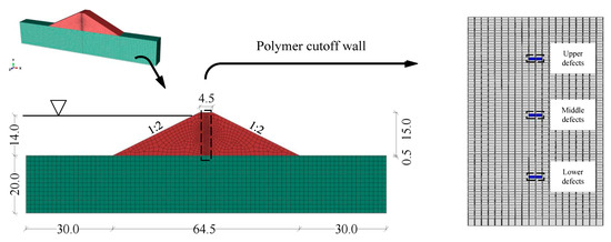
Figure 1.
Three-dimension model of the earth dam with polymer cutoff wall.
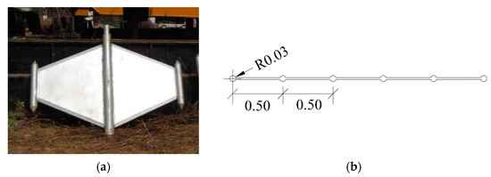
Figure 2.
A special drilling tool and a section of polymer cutoff wall (unit: m). (a) Tri-cone slot-forming plate, (b) Horizontal profile of the polymer cutoff wall model.
3.2. Simulation of Defects in Cutoff Wall
During the construction, when the grouting pipe uplifts too fast, the thickness of the cutoff wall could be uneven; the window could appear when the slot holes connect inadequately (simulation is shown in Figure 3). The permeability coefficient of elements was augmented to simulate flaws. The permeability coefficient of the uneven thickness deficiency element was 10, 100, and 1000 times that of the cutoff wall. Supposed windows are filled in soil, so the permeability coefficient of the deficiency element is equal to that of soil. The steps to simulate random defects are as follows: first, all the cutoff wall elements are selected from the model; second, the construction defect rate is determined; next, random sampling is according to a uniform distribution; and finally, the sample continues until reaching the preset defect rate.
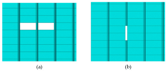
Figure 3.
Schematic diagram of defect simulation. (a) Uneven thickness, (b) Window.
4. Seepage Characteristics Analysis
4.1. Seepage Characteristics under Single Defects
Figure 4 illustrates the pore water pressure distributions of the earth dam, which has an uneven thickness defect in different sizes of 20 cm × 88 cm, 40 cm × 88 cm, and 60 cm × 88 cm in the middle of the wall (the permeability coefficient of deficiency elements is 1000 times that of the intact wall). In addition, the contour maps concern the pore water pressure of the earth dam when there are 20 cm × 3 cm and 60 cm × 3 cm windows in the middle of the cutoff wall (Figure 5). Under the condition of a single defect, there is a similarity among these seepage fields (Figure 4 and Figure 5), because one single defect has little influence on the overall saturated surface of the earth dam, but an effect on the contour distribution of local head nearby (Figure 6).
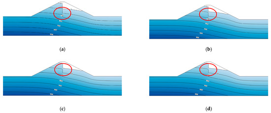
Figure 4.
Pore pressure contour map of earth dam containing anti-seepage wall with an uneven thickness defect (unit: kPa). (a) Complete cutoff wall, (b) Defect size of 20 cm × 88 cm, (c) Defect size of 40 cm × 88 cm, (d) Defect size of 60 cm × 88 cm.
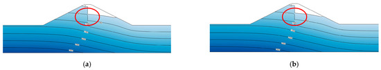
Figure 5.
Pore pressure contour map of earth dam containing polymer cutoff wall with a window (unit: kPa). (a) Defect size of 20 cm × 3 cm, (b) Defect size of 60 cm × 3 cm.
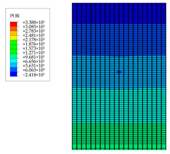
Figure 6.
Local pore pressure distribution of polymer cutoff wall.
When the polymer cutoff wall has uneven thickness defects, compared with the complete cutoff wall, the maximum increase of leakage in the dam section is 0.15 m3/d, and the variation range of saturation line height is 0.15~0.57 m (Figure 7).
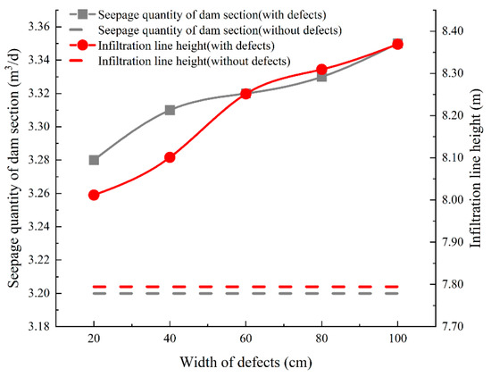
Figure 7.
Relations of seepage quantity, infiltration line, and size of the uneven thickness defect, respectively.
Compared with the same type of defects (Figure 8 and Table 1), the synchronous increases in seepage quantity and the infiltration line mean the anti-seepage ability of the cutoff wall decreases. Although the type, location, size, and permeability coefficient are not the same, one single flaw has few influences on the seepage. In the same conditions, the defects in different positions under the design water level, the closer to the upper wall, the higher the seepage flux and the infiltration line. That implies the water head difference decreases on both sides of the diaphragm (Table 1). That leads to more impact on the seepage and the worse impermeability of the polymer wall, which becomes more acute as the defect rate increasing. Therefore, more concentration on the construction quality of the polymer cutoff wall, particularly the upper part, to prevent the adverse effects on the seepage field caused by constructional deficiency.
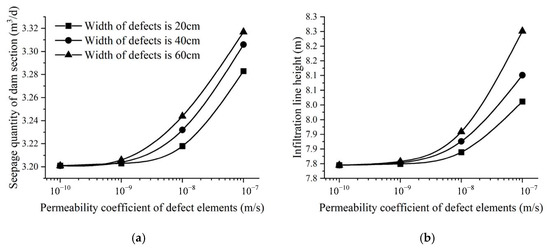
Figure 8.
Variation of the seepage discharge and infiltration line with the permeability coefficient of the defect. (a) Seepage discharge, (b) Infiltration line.

Table 1.
Calculation results of seepage field of polymer cutoff wall earth dam with a single defect.
4.2. Seepage Characteristics under Multiple Defects
Through the previous analysis, attention should be paid to the impact of uneven thickness deficiencies on the seepage field under varying permeability coefficients of imperfection elements and construction defect rates (Table 2). The permeability coefficients of the deficiency elements are equal to 10, 100, and 1000 times that of the normal. The flaw distributions of the cutoff wall result from random sampling as the construction defect rate are 5%, 10%, 15%, and 20% (Figure 9). The flaw distribution is uniform in the cutoff wall without local concentration.
Table 2.
Partial calculation results of seepage field of an earth dam with defective polymer cutoff wall.
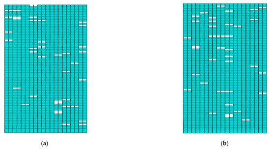
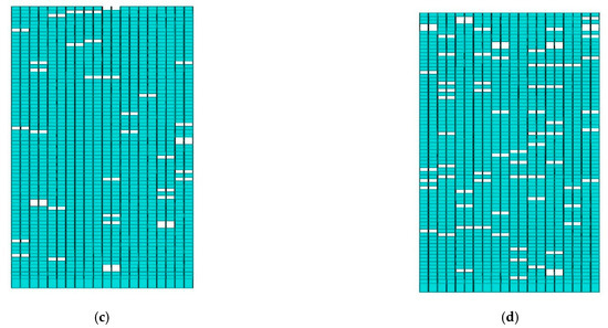
Figure 9.
Random distribution of uneven thickness defects in polymer cutoff wall. (a) Distribution 1st, defect rate of 5%, (b) Distribution 2nd, defect rate of 5%, (c) Distribution 3rd, defect rate of 5%, (d) Distribution 4th, defect rate of 10%.
Table 2 lists the seepage quantity, height of infiltration line and overflow point, and water head difference on both sides of the cutoff wall under random flaws with different defect rates or permeability coefficients. It illustrates that, under the design water level, the seepage quantity of the complete polymer cutoff wall is just 3.2 m3/d, and the water head difference on both sides of the cutoff wall reaches 5.695 m. The seepage field changes slightly in the case of a 5% defect ratio, where the permeability coefficient of deficiency elements rose 10-fold. The seepage flux variations of the dam section are less than 0.06 m3/d, and the water head difference decreases by less than 0.28 m. In the 10-fold increases of permeability coefficient, the seepage field has no obvious distinction whether a single flaw or a deficiency rate below 10%. However, when the same deficiency rate, the increase of the permeability coefficient, produced by the uneven thickness of the polymer wall, will seriously undermine the seepage control ability of the cutoff wall, affecting the overall seepage field. When the permeability coefficient of the flaw elements magnify 100 times, 1000 times, but at most that of the soil, compared with the 10-fold permeability coefficient, the leakage quantity ranged from 1.13 times to 1.27 times, the minimum pore water pressure is 1.35~1.86 times, the water head difference is reduced by 45% and 82%, respectively.
The contour maps of the total water head of the dam under the random uneven thickness defects with different deficiency rates (Figure 10) reveal a growth in defect rate severely cut down on the impermeability of the polymer wall when the deficiency elements have the same permeability coefficient of 100 times. The water head distribution over the flaw rate of 20% approaches that without the cutoff wall. Therefore, in addition to avoiding the uneven thickness, limit the total quantity of flaws to prevent the high defect rate fail the polymer cutoff wall.
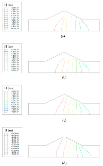
Figure 10.
Contour map of total water head of earth dam under different numbers of uneven thickness defect (unit: m). (a) Complete cutoff wall, (b) 10% defect rate, (c) 20% defect rate, (d) Without cutoff wall.
After further analysis, with the increase of permeability coefficient of the defect element, the changes of seepage discharge, the height of infiltration line, and the height of overflow point all rise rapidly at first and then gradually approach a constant, but the trend of the water head difference is on the contrary. In addition, take the defect rate of 10% for example (partial results are shown in Table 2), these indexes all vary dramatically below the permeability coefficient of 5.00 × 10⁻⁸ m/s and tend to a definite value later. In other words, the variation range of the seepage field gradually decreases and stays stable when the permeability coefficient is over 5.00 × 10⁻⁸ m/s. The impermeability of the polymer cutoff wall has been less than 20% since the defect rate exceeds 10%, which is slightly better than the situation without the cutoff wall.
4.3. Impermeability Index
The polymer wall seems unavoidable to develop local construction deficiencies, especially these two kinds of defects above. The parameter of the seepage quantity reflects exactly the defect characteristics. In practice, it is usually hard to get the exact distribution location of tiny local defects utilizing detection. Therefore, a kind of impermeability index R is proposed as the evaluation index to judge the impermeability and construction quality of polymer cutoff walls. Computed by the variation in seepage flux, which is easier to determine by the existing methods, it can reflect reality with relative accuracy, which is simple to calculate and apply for preliminary on-site judgment.
The numerator is equal to the actual monitoring value of seepage quantity of the earth dam with the polymer wall (Adefect) minus that without the cutoff wall (Awithout), and the denominator is the seepage quantity of the earth dam with the polymer wall in design (Acomplete) minus that without the cutoff wall (Awithout). The ratio is defined as impermeability index R, which not only reflects the anti-seepage property of the polymer wall intuitively but also reflects construction quality.
When R has a higher value (namely approaching 1), it represents better construction quality of the polymer wall and its impermeability (shown in Figure 11). On the contrary, the smaller value of R can imply more local defects in the polymer cutoff wall that need further detection and repair.
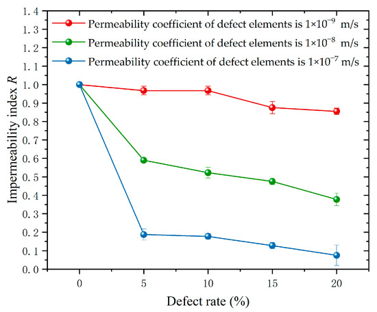
Figure 11.
Relationship between impermeability index R and defect rate of polymer cutoff wall with different permeability coefficients.
5. Conclusions
A 3D finite element model of an earth dam with the polymer cutoff wall is established in this study. The model reflects the real geometry of the polymer cutoff wall and the internal construction flaws, which are windows and uneven thickness. Furthermore, the number, location, and randomness of defects in the wall are simulated to reveal the influences of seepage characteristics on the earth dam. In addition, an index is proposed to reflect the practical impermeability of the polymer cutoff wall.
- In comparison with flaws of the same type, the synchronous increases in seepage quantity and the infiltration line, along with the size or permeability coefficient of defects enlarging, means the anti-seepage ability of the cutoff wall decreases. Although the type, location, size, and permeability coefficient are not exactly the same, one single flaw has few influences on the seepage performance. Under the condition of multiple defects, the seepage flux and the water pore pressure increase, and become more acute as the defect rate increasing. So, controlling the number of defects is vital to limit leakage, for example, by improving and using advanced construction techniques.
- Under the design water level, the more defects close to the upper wall, the more seepage flux and infiltration line increase, which induces a decrease in water head difference on both sides of the wall. That defect distribution leads to more impact on the seepage and the worse impermeability of the polymer wall. Therefore, more concentration on the construction quality of the polymer cutoff wall, particularly the upper part.
- The increase of the permeability coefficient, produced by aggravating the degree of the uneven thickness defect, will seriously undermine the seepage control ability of the cutoff wall, affecting the overall seepage field. The influence of the extreme heterogeneous thickness of polymer cutoff walls may bring more serious consequences than a large area of defect.
- To guarantee the seepage safety of the earth dam, construction quality supervision of the polymer cutoff wall should be ensured to avoid construction deficiency. It is necessary to strengthen the detection and improve the judgment index in order to judge the overall seepage control performance of the polymer wall.
This proposed index is only a preliminary judgment index based on the results obtained above, and the reliability of this index needs to be tested by sensitivity analysis and actual data.
Author Contributions
Conceptualization, B.X. and X.D.; methodology, B.X. and Y.C.; software, Y.C. and S.Z.; validation, Y.C., B.X. and S.Z.; formal analysis, Y.C.; investigation, B.X. and S.Z.; resources, Y.C.; data curation, Y.C.; writing—original draft preparation, Y.C.; writing—review and editing, B.X.; visualization, Y.C.; supervision, M.S. and X.D.; project administration, B.X. and M.S.; funding acquisition, B.X. and M.S. All authors have read and agreed to the published version of the manuscript.
Funding
This research was supported by the National Natural Science Foundation of China with grant No. 52109169 and the Chinese Postdoctoral Science Foundation with grant No. 2021M702951.
Institutional Review Board Statement
Not applicable.
Informed Consent Statement
Not applicable.
Data Availability Statement
Not applicable.
Conflicts of Interest
The authors declare no conflict of interest.
References
- Guo, C.C.; Sun, B.; Hu, D.P.; Wang, F.; Shi, M.; Li, X. A Field Experimental Study on the Diffusion Behavior of Expanding Polymer Grouting Material in Soil. Soil Mech. Found. Eng. 2019, 56, 171–177. [Google Scholar] [CrossRef]
- Yang, J.; Yin, Z.; Laouafa, F.; Hicher, P. Three–Dimensional Hydromechanical Modeling of Internal Erosion in Dike–on–Foundation. Int. J. Numer. Anal. Methods Geomech. 2020, 44, 1200–1218. [Google Scholar] [CrossRef]
- Zhang, X.; Wang, C.; Wong, H.; Jiang, T.; Dong, J. Modeling Dam Deformation in the Early Stage of Internal Seepage Erosion– Application to the Teton Dam, Idaho, before the 1976 Incident. J. Hydrol. 2022, 605, 127378. [Google Scholar] [CrossRef]
- Chen, S.S.; Zhong, Q.M.; Cao, W. Breach Mechanism and Numerical Simulation for Seepage Failure of Earth-rock Dams. Sci. China Technol. Sci. 2012, 55, 1757–1764. [Google Scholar] [CrossRef]
- Wang, F.M.; Li, J.; Shi, M.S.; Guo, C.C. New Seepage-proof and Reinforcing Technologies for Dikes and Dams and Their Applications. J. Hydroelectr. Eng. 2016, 35, 1–11. [Google Scholar] [CrossRef]
- Zhang, H.; Li, Z.; Li, W.; Song, Z.; Ge, W.; Han, R.; Wang, T. Risk Analysis of Instability Failure of Earth–Rock Dams Based on the Fuzzy Set Theory. Water 2021, 13, 3088. [Google Scholar] [CrossRef]
- Galindo, R.; Sánchez-Martín, J.; Olalla Marañón, C. Sustainable Construction of Earth Dams: Use of Heterogeneous Material from the Dam Site. Sustainability 2020, 12, 9940. [Google Scholar] [CrossRef]
- Yu, X.; Wang, Y.K.; Wang, G.; Xue, B.; Zhao, X.; Du, X. Study on Working Behaviors and Improvement Strategies of Concrete Cutoff Wall with Slurry Cake in Thick Soil Foundation. Int. J. Geomech. 2022, 22, 04022075. [Google Scholar] [CrossRef]
- Liang, J.; Du, X.; Fang, H.; Du, M.; Shi, M.; Gao, X.; Han, Y. Numerical and Experimental Study of Diffusion Law of Foamed Polymer Grout in Fracture Considering Viscosity Variation of Slurry. Tunn. Undergr. Space Technol. 2022, 128, 104674. [Google Scholar] [CrossRef]
- Dong, Z.; Xue, B.; Lei, J.; Zhao, X.; Gao, J. Study on Propagation Characteristics of Ground Penetrating Radar Wave in Dikes and Dams with Polymer Grouting Repair Using Finite-Difference Time-Domain with Perfectly Matched Layer Boundary Condition. Sustainability 2022, 14, 10293. [Google Scholar] [CrossRef]
- Li, M.J.; Du, M.R.; Wang, F.M.; Xue, B.; Zhang, C.; Fang, H. Study on the Mechanical Properties of Polyurethane (PU) Grouting Material of Different Geometric Sizes under Uniaxial Compression. Constr. Build. Mater. 2020, 259, 119797. [Google Scholar] [CrossRef]
- Li, M.J.; Fang, H.Y.; Du, M.R.; Zhang, C.; Su, Z.; Wang, F. The Behavior of Polymer-bentonite Interface under Shear Stress. Constr. Build. Mater. 2020, 248, 118680. [Google Scholar] [CrossRef]
- Shi, M.; Wang, F.; Luo, J. Compressive strength of polymer grouting material at different temperatures. J. Wuhan Univ. Technol.-Mater. Sci. Ed. 2010, 25, 962–965. [Google Scholar] [CrossRef]
- Guo, C.C.; Wang, F.M. Mechanism Study on the Construction of Ultra-Thin Antiseepage Wall by Polymer Injection. J. Mater. Civ. Eng. 2012, 24, 1183–1192. [Google Scholar] [CrossRef]
- Wang, F.M.; Guo, C.C.; Gao, Y. Formation of a Polymer Thin Wall Using the Level Set Method. Int. J. Geomech. 2014, 14, 04014021. [Google Scholar] [CrossRef]
- Wang, F.M.; Shi, M.S.; Li, H.J.; Zhong, Y.H. Experimental Study on the Anti-permeability Properties of Polymer Grouting Materials. Adv. Mater. Res. 2011, 284–286, 1952–1955. [Google Scholar] [CrossRef]
- Guo, C.C.; Chu, X.X.; Wang, F.M. The Feasibility of Non-water Reaction Polymer Grouting Technology Application in Seepage Prevention for Tailings Reservoirs. Water Supply 2017, 18, 203–213. [Google Scholar] [CrossRef]
- Hao, M.M.; Wang, F.M.; Li, X.L.; Zhang, B.; Zhong, Y. Numerical and Experimental Studies of Diffusion Law of Grouting with Expansible Polymer. J. Mater. Civ. Eng. 2018, 30, 04017290. [Google Scholar] [CrossRef]
- Fang, H.Y.; Zhang, H.; Xue, B.H.; Gao, J.; Li, Y.; Gao, X.; Tian, A. Coordination Characteristics Analysis of Deformation between Polymer Anti-Seepage Wall and Earth Dam under Traffic Load. Water 2022, 14, 1442. [Google Scholar] [CrossRef]
- Li, J.; Zhang, J.; Wang, Y.; Wang, B. Seismic Response of Earth Dam with Innovative Polymer Antiseepage Wall. Int. J. Geomech. 2020, 20, 04020079. [Google Scholar] [CrossRef]
- Li, J.; Zhang, J.; Xu, J.; Wang, F.; Wang, B.; Li, Q. Dynamic Behavior of Polymer Antiseepage Wall for Earth Dam by Centrifuge Test. Int. J. Geomech. 2018, 18, 04018179. [Google Scholar] [CrossRef]
- Zhang, S.; Xue, B.H.; Wang, J.; Gao, J.; Wang, C.; Li, W. Preliminary Study of Nondestructive Testing of the Polymer Cutoff Wall Based on Vibration Theory. Adv. Mater. Sci. Eng. 2021, 2021, 4444684. [Google Scholar] [CrossRef]
- Guo, C.C.; Yang, J.C.; Shi, M.S.; Cai, B.H.; Li, Z.C.; Guan, H. Improvement of Construction Equipment and Technology of Super-thin Cut-off Walls with Polymer. Adv. Sci. Technol. Water Resour. 2020, 40, 68–71. [Google Scholar] [CrossRef]
- Wang, T.; Xu, L.Q. Three-dimensional Seepage Characteristic Analysis of Core Wall Dam Considering Stochastic Construction Defects. Water Resour. Power 2016, 34, 87–89. [Google Scholar]
- Yang, J.; Cheng, G.; Zhang, P.L.; Wang, J. Sensitivity Analysis of Leakage of Rockfill Dam Caused by Composite Geomembrane Defect. IOP Conf. Ser. Earth Environ. Sci. 2021, 826, 12041. [Google Scholar] [CrossRef]
- Cen, W.J.; Wang, H.; Li, D.J. Influence of Geomembrane Defects in Earth-rock Dam with Different Geomembrane Layouts on Seepage Property and Dam Safety. Eng. J. Wuhan Univ. Eng. Ed. 2018, 51, 589–595. [Google Scholar] [CrossRef]
- Cen, W.J.; Du, X.H.; Geng, L.Y.; He, H.N. Seepage Properties of Geomembrane Faced Earth-rock Dams under Random Multiple Defects. Adv. Sci. Technol. Water Resour. 2018, 38, 60–65. [Google Scholar] [CrossRef]
- Du, X.H.; Cen, W.J.; Wen, Z.Y.; He, H. Impact of Double Defects on Seepage Behavior of Geomembrane Lined Earth-rock Dams. IOP Conf. Ser. Earth Environ. Sci. 2019, 376, 12057. [Google Scholar] [CrossRef]
- Athani, S.; Shivamanth; Solanki, C.; Dodagoudar, G. Seepage and Stability Analyses of Earth Dam Using Finite Element Method. Aquat. Procedia 2015, 4, 876–883. [Google Scholar] [CrossRef]
- Abokwiek, R.; Al Sharabati, M.; Hawileh, R.; Abdalla, J.A.; Sabouni, R.; Husseini, G.A. A Finite Element Model for the Analysis of Seepage Flow of Water Under Concrete Dams. Geotech. Geol. Eng. 2022, 40, 2823–2841. [Google Scholar] [CrossRef]
- Al-Janabi, A.M.S.; Ghazali, A.H.; Ghazaw, Y.M.; Afan, H.A.; Al-Ansari, N.; Yaseen, Z.M. Experimental and Numerical Analysis for Earth-Fill Dam Seepage. Sustainability 2020, 12, 2490. [Google Scholar] [CrossRef]
- Salmasi, F.; Norouzi, R.; Abraham, J.; Nourani, B.; Samadi, S. Effect of Inclined Clay Core on Embankment Dam Seepage and Stability Through LEM and FEM. Geotech. Geol. Eng. 2020, 38, 6571–6586. [Google Scholar] [CrossRef]
- Bashir, A.; Chaudhry, R.; Qureshi, A.L.; Memon, U.; Bheel, N. Understanding the Seepage Behavior of Nai Gaj Dam through Numerical Analysis. Eng. Technol. Appl. Sci. Res. 2022, 12, 8085–8089. [Google Scholar] [CrossRef]
- David, M.P.; Lidija, Z. Finite Element Analysis in Geotechnical Engineering: Theory; Thomas Telford Publishing: London, UK, 1999; pp. 305–323. ISBN 0-7277-2753-2. [Google Scholar]
Publisher’s Note: MDPI stays neutral with regard to jurisdictional claims in published maps and institutional affiliations. |
© 2022 by the authors. Licensee MDPI, Basel, Switzerland. This article is an open access article distributed under the terms and conditions of the Creative Commons Attribution (CC BY) license (https://creativecommons.org/licenses/by/4.0/).