Abstract
Induction heating (IH) applications, assisted with converter topology and their control, have become very attractive in recent years. Independent power control for any induction cooking application with simple converter topology, multi-load handling capacity, and a control technique is still a research hot spot. This paper focuses on developing the dual-frequency converter for delivering power to two loads independently. The switching frequencies of the converter for loads 1 and 2 are selected as 20 and 80 kHz, respectively, and the inverter is operated by multiplexing two switching frequencies. The independent power control is performed using a phase shift control scheme and validated in real-time using a PIC16F877A microcontroller. The prototype of 1 kW is developed and load 1 is operated with 550 W and load 2 is operated with 270 W output power. The independent power control is verified for various values of the control angle () and it is noticed that the efficiency is 91% at 0 and it is above 80% for other values of . The thermal model of the proposed system is studied using COMSOL multiphysics software and the experimental image is recorded using a FLIR thermal imager. It is noted that the temperature rise in the load is 78 C and 38.5 C for loads 1 and 2, respectively, at time t = 180 s.
1. Introduction
Induction heating (IH) finds its application in various fields such as domestic, industrial, and medical because of the isolated heating, safety, high efficiency, high power density, and precise power control characteristics [1,2]. In IH, heat is generated in workpieces or targets due to eddy current losses and hysteresis losses, which arise due to electromagnetic phenomena [3,4]. The skin depth of the material depends on the frequency, state of magnetization, temperature, heat penetration, etc. [4]. The components involved in induction heating are an AC power source, rectifier, high-frequency inverter, work coil, and piece. The electromagnetic field produced by the working coil links with the workpiece, which, in turn, produces heat on it. The heat produced in the workpiece is directly proportional to the eddy current, a high-frequency ac supply is required to get more eddy current losses [5].
One of the applications of induction heating is cooking, which is normally used in day-to-day life. It requires multiple loading arrangements that must be controlled independently [6]. Several researchers have been performing research on IH frequently over the past few years. Several inverter configurations have been proposed in recent years for cooking appliances with multiple loads, reduced number of components, and improved productivity. Forest F et al., developed a dual load IH system in which parallel-connected resonant capacitors are connected to the load through electromechanical relay switches. In this arrangement, one of the loads colored red is served as the master and another as the slave [7]. Due to the electromechanical switches and larger capacitors, the system becomes more expensive with a complex control.
A three-leg, dual-load IH system emerged in [8], with one of the legs placed commonly for the loads. This system uses a reduced number of components and handles more current when both loads are powered at the same time. In [9], a power factor correction converter topology with dual output power is produced for an induction cooking system. The asymmetric voltage cancellation technique was used for performing the independent power control of each load. The developed system results in even more harmonics in voltage output. A multi-inverter and multi-load topology were developed by O. Lucía et al., with pulse density modulation for regulating the output power [10]. Though the smooth power, control is achieved, and independent power is not feasible with the technique. An induction cooking system with dual-frequency, two outputs, and independent power control using ADC is developed in [11]. In [12], a multi-output converter topology with multiple coil arrangements and zero voltage switching is proposed. The coils were organized in a matrix structure and controlled using individual switches for each load. The performance of the system is good for multiple loading applications and but the system size becomes complex for single load applications.
A single-stage AC-AC converter topology was proposed to reduce the rectifier and filter circuit. A four-quadrant switching device was developed to convert 50 Hz alternating current to higher frequency alternating currents [13]. It uses insulated gate bipolar transistor (IGBT) switches connected in anti-series with each other. Due to this, during high-frequency operation, the source current was found to be distorted Ṫhis problem was avoided by employing an electromagnetic compatibility filter [14]. The power control was deployed by adjusting the switching frequency, which resulted in more switching losses. This problem is overcome by developing the multiphase series resonant inverter with multiple coils arranged in a matrix manner [2]. The power control is performed using the phase shift control technique, and the efficiency of the system is 97% at maximum load conditions. This scheme results in poor regulation for the variations in the load.
For IH applications, effective power control is indispensable. Variable frequency control, pulse amplitude modulation (PAM), and pulse density modulation control are used to regulate the output power for cooking applications. The output power of a fixed load is often controlled by using variable frequency (VF) control [15]. This scheme results in more switching losses when the inverter is operated below the resonant frequency. Hence, for the fixed load operation, PAM is often preferred since the power output may be adjusted by altering the inverter’s duty cycle by keeping the switching frequency constant [16]. Pulse density modulation control (PDM) is the fixed frequency control in which control is deployed by superimposing two frequencies. This control results in better soft switching, maximum efficiency, and smooth power regulation but results in more acoustic noise [17].
A multi-load fed IH system with reduced components has been developing in recent years. A cost-effective, three-switch inverter was developed for two load cooking applications [18]. Simultaneous and independent power control was achieved using the ADC technique. This topology cannot be used for a variable-sized coil. A multi-inverter-based flexible surface IH cooktop was developed using GaN-HEMT [19]. The inverters were triggered by detecting the load using a real-time pot detection method, which requires a high magnetic coupling effect between the coil and load. A hybrid PSC and variable frequency control was proposed for IH applications using FPGA [20]. PSC was used to vary the output power as per the load requirement, and variable frequency control was used to attain the soft switching.
Viriya et al., developed a novel transition phase shift control for an FB inverter-fed IH system [21]. The ZVS and non-ZVS regions of operations were identified by comparing with the conventional PSC. By selecting the proper control angle, the inverter was operated in the ZVS mode. A double half-bridge SRI with phase shift modulation was proposed for IH applications [22]. The developed topology uses a common capacitor for dual loads to create resonance. The performance of the inverter was studied considering the identical parameter for both loads. A single-stage direct AC-AC boost FB converter was proposed for high-frequency IH applications [23]. The output power is controlled using a phase shift PWM control technique with a wide, soft-switching range. The boost inductor improves the source side power factor. A multi-load three-phase direct AC-AC resonant converter was proposed for induction metal melting applications [24]. The performance of the converter was tested with three coils, which were arranged in a coaxial structure. PSC was used to vary the output power, which resulted in ZVS operation.
It is noted from the existing literature that there is a quest to develop a control technique with improved load handling capacity with reduced elements, and independent power control is very meaningful. This work focus on a simple dual-frequency converter with a PSC scheme to overcome the soft switching issue with the existing control schemes. The developed converter handles two cooking loads, and the PS control technique aids in controlling the output power independently. A comprehensive range of power control is achieved using the PS control with simple logic, and a wide range of ZVS is achieved.
2. Analysis of the Circuit and Operating Modes
2.1. Dual-Output High-Frequency Inverter
Dual-output inverters produce two different output powers for each load. The circuit diagram of the proposed system is illustrated in Figure 1. In this control scheme, the high-frequency and low-frequency switching pulses are superimposed and applied to the inverter switches. The IH system consists of the primary working coil and pan as the load. Both are electrically isolated and magnetically coupled with each other, which resembles the transformer action. The equivalent resistance and inductance, referred to as the primary, is represented as and at a fixed operating frequency [25,26]. The referred equivalent parameters of loads 1 and 2 are represented as and , respectively. To create resonance, capacitors and are connected in series with loads 1 and 2, respectively.
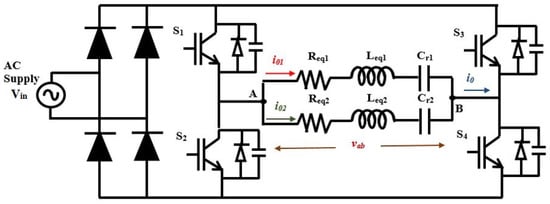
Figure 1.
Circuit diagram of the dual-output inverter.
2.2. Dual-Frequency Pulse Generation and Analysis of the Load
Dual output is produced by combining two different switching frequencies to get the desired output voltage [27]. The switching pattern for and is produced by superimposing two different frequencies such that, during the turn-on time of the low-frequency signal, the high-frequency signal is allowed to trigger the inverter switch. Hence, the envelope of the high-frequency pulses is followed in the positive cycle of the voltage and zero for the negative cycle. When the low-frequency signal is turned off, the positive half cycle of the load voltage becomes zero volts. This pattern of pulse generation is repeated for the other switches, and , with 180 phase shifts. The output of the inverter is the superimposition of both frequencies.
The resonant frequency of load 1 is and load 2 is . Load 1 is intended to operate with HFAC supply and act as an open circuit by capacitive reactance for low-frequency supply. Likewise, load 2 is typically equipped to operate at LFAC supply and behave like an open circuit by inductive reactance for a high-frequency supply. Figure 2a represents the equivalent circuit of the IH load with HFAC supply and Figure 2b shows the equivalent circuit of the IH load with LFAC supply.
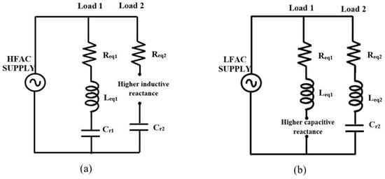
Figure 2.
Equivalent circuit of IH load with (a) HFAC supply and (b) LFAC supply.
The fundamental rms value of the load voltage is
The load currents are
The impedance of each load is
The output power of loads 1 and 2 are
where
The total output power () of the inverter is expressed as
The normalized angular frequencies are
The quality factor of the coil is
2.3. Selection of Dual Switching Frequency
In this control method, two switching frequencies are selected, and the inverter is triggered by superimposing those frequencies. The selection of the frequencies is carried out in such a manner that each load responds to one frequency and acts as an open circuit for other frequency. The amplitude of the output voltage () over both loads stays the same since both of them are connected in parallel. However, the reactive current of either frequency would not flow between other loads, as they are isolated concerning the frequency of operation. In this control scheme, 20 and 80 kHz switching frequencies are chosen to make loads 1 and 2 active. The resonance frequency of the load is varied by choosing the appropriate resonant capacitors ( and ) for the same values of coil inductance ( = ).
2.4. Operating Modes
The operating modes of the dual-frequency inverter are shown in Figure 3. The full bridge SRI’s output voltage is comprised of three levels, and the load current is sinusoidal. The switching frequency of load 1 is selected as 20 kHz, and load 2 is selected as 80 kHz. The dual-frequency converter is triggered by multiplexing both switching frequencies. The associated modes of the operation modes are detailed below:
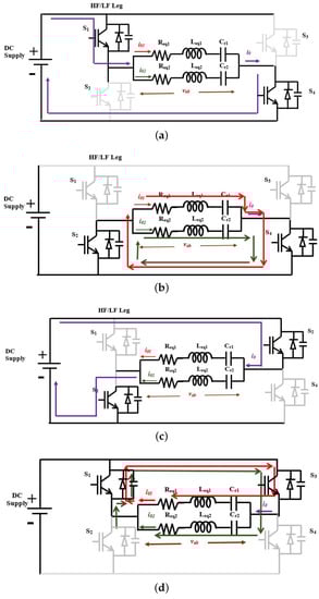
Figure 3.
Operation of the dual-frequency inverter in (a) Mode 1, (b) Mode 2, (c) Mode 3, and (d) Mode 4.
Mode 1: The status of switches and are in an on-off state, respectively. The equivalent circuit of mode 1 is shown in Figure 3a. The current at junction ‘A’ is divided into LF and HF components to energize the respective loads.
Mode 2: The switches and are turned off. The currents and dissipate the stored energy through an anti-parallel diode connected across , as illustrated in Figure 3b. The load voltage is zero, and and remain in the same direction.
Mode 3: In this mode, is turned off and is turned on. The direction of the current flow during mode 1 is shown in Figure 3c. The supply current reaches the negative terminal through loads 1 and 2 in the opposite direction to that of mode 1.
Mode 4: In this mode, both switches are in the off state. The inductor dissipates the stored energy as currents and through an anti-parallel diode connected across , as illustrated in Figure 3d.
2.5. Phase Shift Control-Based Pulse Generation
The necessity of independent power control is inevitable when multiple loads are used in IH systems. The PS control technique is used to achieve the aforementioned task without changing the switching frequency. This results in ZVS for the entire range of power variations. The typical PS-based control output waveforms are shown in Figure 4. In this case, it is possible to vary the phase shift of high-frequency (HF)/low-frequency (LF) or both HF and LF to control the output power as desired. Let and represent the on and off time of the low-frequency pulses, respectively, and and represent the on and off time of the high-frequency pulses, respectively.
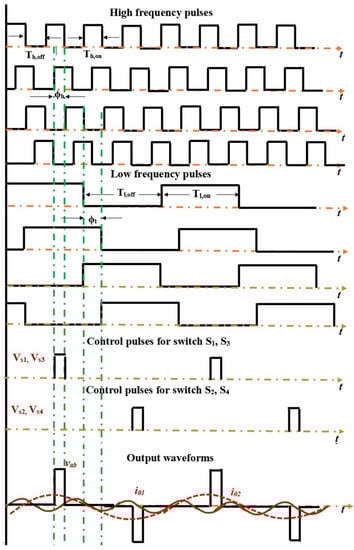
Figure 4.
PS-based pulse generation.
The PS-controlled output currents are
The energy stored in the coil is expressed as
The power output can be varied by adjusting . The energy accumulated during the off-cycle freewheels within the IH load.
3. Experimental Results of the Phase Shift Control Technique
The validation of the proposed converter with the control algorithm is developed using PIC16F877A. The output pulses are amplified using TLP250 driver IC. The dual-frequency converter is developed with two H20R1203 IGBTs. The load currents are measured using SIGLENT CP4060 current probe, and waveforms are recorded using an MDO3024 optical oscilloscope. The temperature rise in the load is studied using FLIR E75 24, a thermal imager. The photograph of the dual-frequency converter is shown in Figure 5. The developed dual-frequency series resonant inverter is validated for two cooking loads as per the specifications given in Table 1.
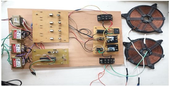
Figure 5.
Test configuration of the dual-frequency inverter.

Table 1.
Design specifications of the dual-frequency inverter.
A simple and accurate power control scheme is essential in the IH system to change the temperature of the load as per the user’s requirements. The phase shift control technique is used to vary the output power for a dual-frequency inverter-fed induction cooking system. The nominal pulse generation, output voltage, and current waveform for the developed system are briefed in [27]. In this work, the performance of the system with phase control logic is studied and compared with the existing work. In the real-time operation of a multi-load induction cooking system, independent power control is necessary. The PS control technique ensures individual power control of different loads. The system is evaluated with the following scenarios:
To have control over the output power, a dual-frequency inverter is operated with various phase angles. As per the specifications, load 1 is designed to handle 550 W, and load 2 is designed to handle 270 W with = 11 . With = 0 and = 90, the output power is 550 W for load 1 and 135 W for load 2. The corresponding waveforms are illustrated in Figure 6. The main output voltage and current waveforms for loads 1 and 2 are depicted in Figure 6a,b, respectively. It is inferred that the net power developed in load 1 is 550 W, and load 2 is reduced to 135 W for the selected phase angle.
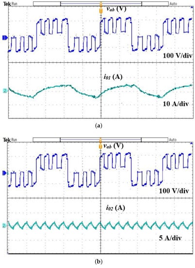
Figure 6.
Main output voltage and current waveforms for = 0 and = 90. (a) Load 1, (b) Load 2.
As the set power of load 1 is maintained as 550 W and varied from 275 to 260 W in load 2, the controller generates the pulses with = 0 and = 170 to achieve the set power, and its corresponding results are shown in Figure 7. The output voltage and current waveform of loads 1 and 2 are illustrated in Figure 7a,b, respectively. To validate the credibility of the control technique, load 1’s power is varied from 550 to 275 W, and load 2’s power is maintained as 275 W. The corresponding output voltage and current waveform of loads 1 and 2 are illustrated in Figure 8a,b, respectively. The load output power is determined by , where is the rms value of the load output current. The input power is calculated by multiplying the average values of the DC input voltage and current. The efficiency of various phase angles is listed in Table 2.
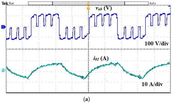
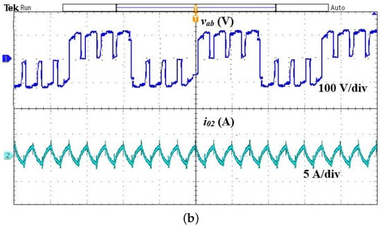
Figure 7.
Main output voltage and current waveforms for = 0 and = 170. (a) Load 1, (b) Load 2.
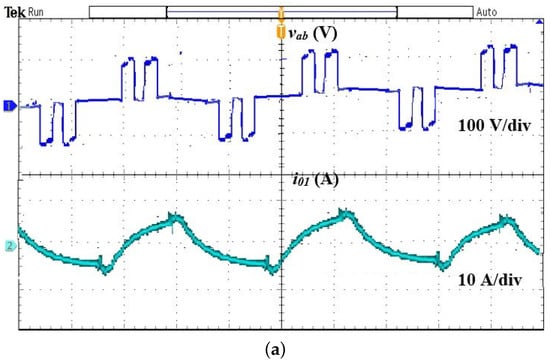
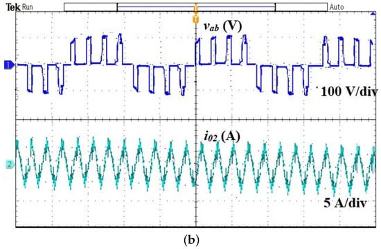
Figure 8.
Main output voltage and current waveforms for = 90 and = 0. (a) Load 1, (b) Load 2.
Table 2.
Efficiency for various .
The temperature study is carried out in the COMSOL multiphysics software. FEM simulation is analyzed using heat transfer and magnetic field solver by providing current, switching frequency, and load properties as the input. The system geometry has meshed with 15274 triangular elements. The simulated and experimental temperature profiles for loads 1 and 2 are shown in Figure 9a–d. The temperature rise is recorded at time t = 180 s for both loads, and it is observed that the highest temperature difference is 48.8%, as the power difference between the two loads is 49%.
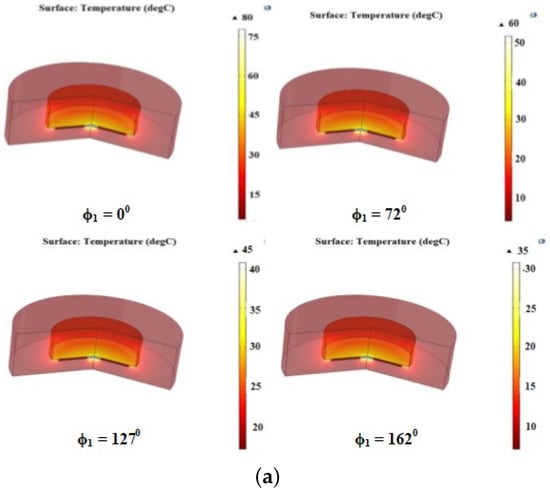
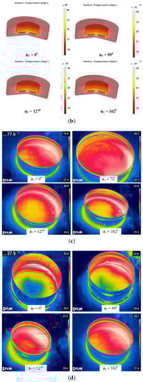
Figure 9.
Simulated thermal image of (a) load 1 and (b) load 2; Experimental thermal image of (c) load 1 (d) and load 2.
The temperature plot concerning is given in Figure 10. It is found that, at = 0, the heat developed in load 1 is 77.6 C and in load 2 is 37.9 C. Figure 11 shows the efficiency of the dual-frequency converter-fed IH system, and it is observed that the maximum efficiency is 91% at = 0 and greater than 80% for other control angles. The performance comparison of various inverters for cooking applications is shown in Table 3. It is inferred that the proposed inverter is capable of handling two loads with two semiconductor switches. Further, among the compared topologies, the proposed inverter has the highest maximum efficiency (91%) at the rated output power.
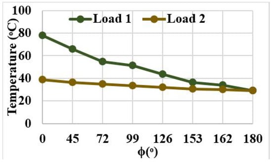
Figure 10.
Temperature plot for various values of ().
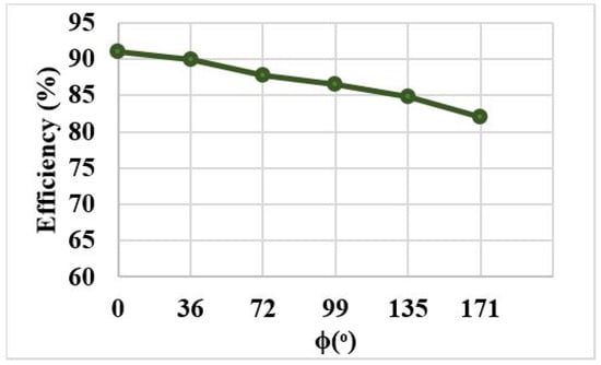
Figure 11.
Efficiency of the proposed system.
Table 3.
Performance comparison of various inverters.
4. Conclusions
In this work, to feed power to multi-loads, a dual-frequency converter is developed. The inverter is operated by multiplexing two switching frequencies, say 20 and 80 kHz, and power control is deployed using phase shift control logic. It is concluded that the output power is controlled from 0% to 100% of the rated power, and the maximum efficiency is 91% at 0 phase angle and greater than 80% for other control angles. Independent power control is achieved in the system by controlling the power in one load without disturbing the other. The thermal model of the proposed system is studied using COMSOL multiphysics software, and the experimental image is recorded using FLIR thermal imager. It is noted that the temperature rise in the load is 78 C and 38.5 C for loads 1 and 2, respectively, at t = 180 s. Though the inverter feeds power to multi-loads, it is not uniform across the loads due to multi-frequency operation. Hence, a topology with uniform power distribution can be developed.
Author Contributions
Data curation, P.V. and S.K.; Formal analysis, P.V., S.K. and V.K.S.; Funding acquisition, T.S.B. and K.N.B.M.H.; Methodology, P.V. and V.K.S.; Project administration, T.S.B. and R.K.; Resources, S.K. and V.K.S.; Supervision, R.K.; Writing–original draft, P.V. All authors have read and agreed to the published version of the manuscript.
Funding
This research was funded (APC) by Yayasan Universiti Teknologi Petronas YUTP-FRG 1/2021: 015LC0-349.
Institutional Review Board Statement
Not applicable.
Informed Consent Statement
Not applicable.
Data Availability Statement
Not applicable.
Conflicts of Interest
The authors declare no conflict of interest.
Nomenclature
The following abbreviations are used in this manuscript:
| Load 1’s resonant frequency | |
| Load 2’s resonant frequency | |
| Input voltage | |
| Load voltage | |
| Pre-charged capacitor 1 voltage | |
| Pre-charged capacitor 2 voltage | |
| Resonant capacitor 1’s voltage | |
| Resonant capacitor 2’s voltage | |
| Load 1’s output current | |
| Load 2’s output current | |
| Load 1’s net resistance | |
| Load 2’s net resistance | |
| Load 1’s net inductance | |
| Load 2’s net inductance | |
| Load 1’s resonant capacitor | |
| Load 2’s resonant capacitor | |
| Load 1’s net impedance | |
| Load 2’s net impedance | |
| Load 1’s output power | |
| Load 2’s output power | |
| Total power | |
| Load 1’s resonant frequency | |
| Load 2’s resonant frequency | |
| PS-based power for load 1 | |
| PS-based power for load 2 | |
| Switching frequency of load 1 | |
| Switching frequency of load 2 | |
| Control angle of load 1 | |
| Control angle of load 2 |
References
- Vishnuram, P.; Ramachandran, G.; Ramasamy, S.; Dayalan, S. A comprehensive overview of power converter topologies for induction heating applications. Int. Trans. Electr. Energy Syst. 2020, 30, e12554. [Google Scholar] [CrossRef]
- Gomes, R.C.M.; Vitorino, M.A.; Acevedo-Bueno, D.A.; Corrêa, M.B.d.R. Multiphase Resonant Inverter with Coupled Coils for AC–AC Induction Heating Application. IEEE Trans. Ind. Appl. 2020, 56, 551–560. [Google Scholar] [CrossRef]
- Lucía, O.; Maussion, P.; Dede, E.J.; Burdío, J.M. Induction Heating Technology and Its Applications: Past Developments, Current Technology, and Future Challenges. IEEE Trans. Ind. Electron. 2014, 61, 2509–2520. [Google Scholar] [CrossRef]
- Komeda, S.; Fujita, H. A Phase-Shift-Controlled High-Frequency Cycloconverter for Induction Heaters. IEEE Trans. Power Electron. 2017, 99, 1. [Google Scholar] [CrossRef]
- Moreland, W.C. The Induction Range: Its Performance and Its Development Problems. IEEE Trans. Ind. Appl. 1973, IA-9, 81–85. [Google Scholar] [CrossRef]
- Forest, F.; Faucher, S.; Gaspard, J.; Montloup, D.; Huselstein, J.; Joubert, C. Frequency-Synchronized Resonant Converters for the Supply of Multiwinding Coils in Induction Cooking Appliances. IEEE Trans. Ind. Electron. 2007, 54, 441–452. [Google Scholar] [CrossRef]
- Forest, F.; Laboure, E.; Costa, F.; Gaspard, J.Y. Principle of a multi-load/single converter system for low power induction heating. IEEE Trans. Power Electron. 2000, 15, 223–230. [Google Scholar] [CrossRef]
- Burdio, J.M.; Monterde, F.; Garcia, J.R.; Barragan, L.A.; Martinez, A. A two-output series-resonant inverter for induction-heating cooking appliances. IEEE Trans. Power Electron. 2005, 20, 815–822. [Google Scholar] [CrossRef]
- Zenitani, S.; Okamoto, M.; Hiraki, E.; Tanaka, T. A charge boost type multi output full bride high frequency soft switching inverter for IH cooking appliance. In Proceedings of the 14th International Power Electronics and Motion Control Conference EPE-PEMC 2010, Ohrid, North Macedonia, 6–8 September 2010; pp. T2-127–T2-133. [Google Scholar] [CrossRef]
- Lucía, O.; Burdío, J.M.; Barragan, L.A.; Acero, J.; Millán, I. Series-Resonant Multiinverter for Multiple Induction Heaters. IEEE Trans. Power Electron. 2010, 25, 2860–2868. [Google Scholar] [CrossRef]
- Papani, S.K.; Neti, V.; Murthy, B. Dual frequency inverter configuration for multiple-load induction cooking application. IET Power Electron. 2015, 8, 591–601. [Google Scholar] [CrossRef]
- Sarnago, H.; Guillén, P.; Burdío, J.M.; Lucia, O. Multiple-Output ZVS Resonant Inverter Architecture for Flexible Induction Heating Appliances. IEEE Access 2019, 7, 157046–157056. [Google Scholar] [CrossRef]
- Hosseini, S.; Sharifian, M.; Sabahi, M.; Yazdanpanah, A.; Gharehpetian, G. Bi-directional power electronic transformer for induction heating systems. In Proceedings of the 2008 Canadian Conference on Electrical and Computer Engineering, Dhaka, Bangladesh, 20–22 December 2008; pp. 000347–000350. [Google Scholar] [CrossRef]
- Lucia, O.; Carretero, C.; Burdio, J.M.; Acero, J.; Almazan, F. Multiple-Output Resonant Matrix Converter for Multiple Induction Heaters. IEEE Trans. Ind. Appl. 2012, 48, 1387–1396. [Google Scholar] [CrossRef]
- Vishnuram, P.; Ramachandran, G. Capacitor-Less induction heating system with self-resonant bifilar coil. Int. J. Circuit Theory Appl. 2020, 48, 1411–1425. [Google Scholar] [CrossRef]
- Bhaskar, D.; Yagnyaseni, N.; Maity, T.; Vishwanathan, N. Comparison of control methods for high frequency IH cooking applications. In Proceedings of the 2014 Power and Energy Systems: Towards Sustainable Energy 2014, Bangalore, India, 13–15 March 2014; pp. 1–6. [Google Scholar] [CrossRef]
- Vishnuram, P.; Ramachandran, G.; Ramasamy, S. A Novel Power Control Technique for Series Resonant Inverter-Fed Induction Heating System with Fuzzy-Aided Digital Pulse Density Modulation Scheme. Int. J. Fuzzy Syst. 2017, 20, 1115–1129. [Google Scholar] [CrossRef]
- Salvi, B.; Porpandiselvi, S.; Vishwanathan, N. A Three Switch Resonant Inverter for Multiple Load Induction Heating Applications. IEEE Trans. Power Electron. 2022, 37, 12108–12117. [Google Scholar] [CrossRef]
- Jang, E.; Kwon, M.J.; Park, S.M.; Ahn, H.M.; Lee, B.K. Analysis and Design of Flexible-Surface Induction-Heating Cooktop with GaN-HEMT-Based Multiple Inverter System. IEEE Trans. Power Electron. 2022, 37, 12865–12876. [Google Scholar] [CrossRef]
- Sankhe, D.N.; Sawant, R.R.; Rao, Y.S. FPGA-Based Hybrid Control Strategy for Resonant Inverter in Induction Heating Applications. IEEE J. Emerg. Sel. Top. Ind. Electron. 2022, 3, 156–165. [Google Scholar] [CrossRef]
- Viriya, P.; Yongyuth, N.; Matsuse, K. Analysis of Two Continuous Control Regions of Conventional Phase Shift and Transition Phase Shift for Induction Heating Inverter under ZVS and NON-ZVS Operation. IEEE Trans. Power Electron. 2008, 23, 2794–2805. [Google Scholar] [CrossRef]
- Lucia, O.; Acero, J.; Burdio, J.; Carretero, C. Phase-shift modulation in double half-bridge inverter with common resonant capacitor for induction heating appliances. IET Power Electron. 2015, 8, 1128–1136. [Google Scholar] [CrossRef]
- Mishima, T.; Sakamoto, S.; Ide, C. ZVS Phase-Shift PWM-Controlled Single-Stage Boost Full-Bridge AC–AC Converter for High-Frequency Induction Heating Applications. IEEE Trans. Ind. Electron. 2017, 64, 2054–2061. [Google Scholar] [CrossRef]
- Gomes, R.C.M.; Vitorino, M.A.; Acevedo-Bueno, D.A.; CorrEa, M.B.d.R. Three-Phase AC–AC Converter with Diode Rectifier for Induction Heating Application with Improved Input Current Quality and Coil Modeling. IEEE Trans. Ind. Appl. 2021, 57, 2673–2681. [Google Scholar] [CrossRef]
- Acero, J.; Carretero, C.; Alonso, R.; Burdio, J.M. Quantitative Evaluation of Induction Efficiency in Domestic Induction Heating Applications. IEEE Trans. Magn. 2013, 49, 1382–1389. [Google Scholar] [CrossRef]
- Meng, L.; Cheng, K.; Chan, K.; Lu, Y. Variable turn pitch coils design for heating performance enhancement of commercial induction cooker. Power Electron. IET 2012, 5, 134–141. [Google Scholar] [CrossRef]
- Vishnuram, P.; Ramachandran, G. A simple multi-frequency multiload independent power control using pulse density modulation scheme for cooking applications. Int. Trans. Electr. Energy Syst. 2021, 31, e12771. [Google Scholar] [CrossRef]
- Huang, M.S.; Liao, C.C.; Li, Z.F.; Shih, Z.R.; Hsueh, H.W. Quantitative Design and Implementation of an Induction Cooker for a Copper Pan. IEEE Access 2021, 9, 5105–5118. [Google Scholar] [CrossRef]
- Esteve, V.; Jordán, J.; Dede, E.J.; Sanchis-Kilders, E.; Martinez, P.J.; Maset, E.; Gilabert, D. Optimal LLC Inverter Design with SiC MOSFETs and Phase Shift Control for Induction Heating Applications. IEEE Trans. Ind. Electron. 2022, 69, 11100–11111. [Google Scholar] [CrossRef]
- Oh, Y.; Yeon, J.; Kang, J.; Galkin, I.; Oh, W.; Cho, K. Sensorless Control of Voltage Peaks in Class-E Single-Ended Resonant Inverter for Induction Heating Rice Cooker. Energies 2021, 14, 4545. [Google Scholar] [CrossRef]
Publisher’s Note: MDPI stays neutral with regard to jurisdictional claims in published maps and institutional affiliations. |
© 2022 by the authors. Licensee MDPI, Basel, Switzerland. This article is an open access article distributed under the terms and conditions of the Creative Commons Attribution (CC BY) license (https://creativecommons.org/licenses/by/4.0/).