Article

Impact of Transformer Topology on Short-Circuit Analysis in Distribution Systems with Inverter-Based Distributed Generations

1
Korea Electric Power Research Institute, Daejeon 34056, Korea
2
School of Electric Engineering, Korea University, Seoul 02841, Korea
*
Author to whom correspondence should be addressed.
Sustainability 2022, 14(15), 9781; https://doi.org/10.3390/su14159781
Submission received: 20 June 2022 / Revised: 3 August 2022 / Accepted: 5 August 2022 / Published: 8 August 2022

Abstract

:
Distributed energy resources (DERs), recently introduced into distribution systems, are mainly inverter-based distributed generations (IBDGs), which have different short-circuit behaviors from conventional synchronous-based distributed generations (SBDGs). Hence, this study presents a comprehensive analysis of the short-circuit behaviors of distribution systems with IBDGs, based on sequence networks and superposition, from the perspectives of interconnected transformers, and observes the flow of zero-sequence fault currents with different transformer topologies. Moreover, two- and three-winding transformers with various bank connection types and groundings are investigated. It was concluded that the transformer topology and its grounding influence the fault current contribution in zero-sequence networks, and the high penetration of IBDGs alters the fault current magnitude and phase angles.

1. Introduction

Owing to the international efforts expended to cope with the climate crisis and the demand for non-carbon energy, the importance of renewable energy sources has increased, and the era of the global energy transition has begun. The energy transition is changing conventional energy systems, which have relied on fossil fuels such as coal and oil, into systems based on renewable energy, such as solar and wind [1,2,3,4,5]. While existing energy systems are centralized in power plants, renewable energy is installed in a distributed manner [6,7]. In other words, as renewable energy increases, distributed energy resources (DERs) have been increasingly used in distribution systems. For example, in Germany, 57% of all the solar energy plants installed in 2015 were connected to low-voltage distribution systems [8]. As a result, the effects of DERs are no longer negligible and thus cause various problems in distribution system planning and operation.
Traditional distribution systems have radial structures, thus maintaining unidirectional protection coordination, whereby fault sections are blocked by relays that monitor the magnitudes of fault currents. However, in view of their restructured forms, due to the transition to alternative energy sources, distribution systems comprise a growing number of DERs and thus contribute to reverse fault currents that eventually adversely affect the protection coordination response [9,10]. To solve this problem, distribution system operators must replace existing protective relays based on overcurrent with directional or adaptive ones. However, this upgrade would lead to high costs that would hinder the introduction of additional renewable energy technologies. Accordingly, a fault analysis that can accurately predict and assess the DER effect is essential.
Like a diesel generator, a conventional DER is a synchronous-based distributed generation (SBDG), which has a rotating component (i.e., a rotor) that transfers mechanical energy into the electrical one or vice versa. This SBDG maintains the terminal voltage, thereby working as a voltage source even in fault conditions. However, most renewable energy resources, such as photovoltaics and wind turbine generators, are inverter-based distributed generations (IBDGs), which are power-electronics-based devices that convert direct currents to alternating currents and operate as current sources at a steady state [11,12,13,14]. Therefore, the fault current magnitudes of IBDGs are equal to one or two times their rated currents and are very small compared with those of typical SBDGs [15,16,17]. Kou et al. [18] showed that the solar farm might work as a negative-sequence source during faults, pointing out that the fault response of solar farms can interfere with conventional relays.
Recently, the IBDG has improved based on grid-support functions or control methods. A wind turbine control scheme may suppress the negative-sequence component of short-circuit currents and thus requires the injecting of the negative-sequence current [19]. Similarly, Liu [20] changed the phase angle of the fault current to minimize the system’s fault current. However, as many inverters in the field have no such functional capabilities, the distribution system operator still needs to adequately perform fault analysis, which calculates short-circuit currents under various fault conditions.
Many fault analysis methods that reflect the characteristics of IBDGs have been studied [21,22,23,24,25]. In [21], the authors calculated the fault current contributions due to IBDGs using the forward–backward sweep method for the steady-state analysis and differential equations for the transient analysis. Kim [22] presented a calculation method for the fault current contribution of IBDGs at balanced conditions, whereby the IBDGs were considered to be limited or unlimited current sources. Mathur et al. [23] considered various voltage-dependent control modes of IBDGs for the short-circuit analysis of radial and meshed distribution systems. Additionally, in [24], it was highlighted that the fault current contribution due to unbalanced IBDG sources should be considered to achieve accurate short-circuit analysis. Li and Wang [25] reduced the fault current computation time in systems with IBDGs.
Table 1 summarizes the literature survey results of short-circuit analyses. Several researchers [19,20,21,22,23,24,25] have not considered the interconnection transformer topology, which determines how to link three-phase windings among terminals (e.g., in delta or wye). This transformer topology is a critical factor affecting zero-sequence fault current flows into the fault point. Therefore, for accurate fault analysis of systems with IBDGs, it is necessary to treat DERs as current sources and to consider the interconnection transformer topology. In this sense, this study proposes a comprehensive short-circuit analysis for power grids with IBDGs that considers the interconnection transformer topology. Based on this analysis, increased fault analysis accuracy can be achieved for various interconnection transformer topologies, which can help to revise the grid codes and protective schemes.
Many researchers and field operators have developed methods that can calculate the fault currents of transmission systems with synchronous-based generations, as described in [26]. However, the methodology used to deal with the systems with IBDGs has not matured yet. In this study, a fault analysis was conducted on the modified system of [26] by replacing synchronous generations with IBDGs. It is important to emphasize that the fault analysis method presented in this study can also be applied to distribution systems. A fault analysis based on the imbalanced operation and unsymmetric structure of distribution systems was conducted by Cho et al. [27].
This paper presented a calculation method of the fault currents of unbalanced distribution systems. Overall, the novelties and contributions of this study are as follows:
  • A detailed approach that can conduct fault analyses with IBDGs is presented while considering the interconnection transformer topology that can impact the symmetric components of fault currents. This thorough approach helps engineers or researchers to study any types of distribution systems with SBDGs or IBDGs.
  • Different fault behaviors caused by various transformer topologies are studied, including D-Yg, Yg-D, Yg-D-Yg, D-D-Yg, and Y-D-Yg.
  • The transformer grounding impact on the zero-sequence fault current contributions of DERs and the total fault current are analyzed.
  • Ultimately, this study can give insights on how to practically design a transformer topology and its grounding in distribution systems.
The rest of this paper is organized as follows. Section 2 first describes a typical distribution system model and the sequence networks of various transformer bank connections, and then, Section 3 investigates the relationships between the transformer topology and the fault current contribution. In Section 4, this approach studies how the fault behaviors of IBDGs differ from those of the conventional SBDGs and then analyzes the impacts of the interconnection transformer topology on short-circuit flows in Section 5, drawing key findings at the ends of Section 4 and Section 5. Finally, the conclusions are presented in Section 6.

2. Materials and Methods

This section describes the basic model and explains the relationship between transformer topology and short-circuit analysis. Figure 1 shows a general power system to be studied in this work. G2 represents a distributed generator (DG), which can be an SBDG or an IBDG in this work, while [27] tested an SBDG only.
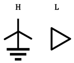
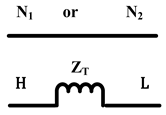
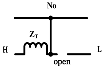
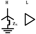
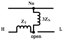
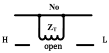
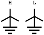
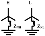
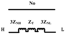
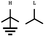
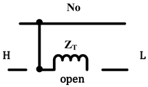
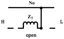
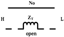
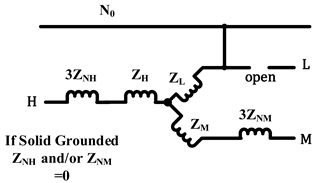
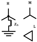
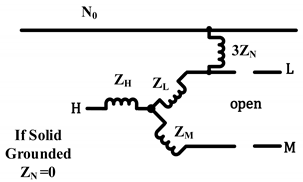
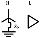
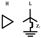
The voltage rating of the bus on which the G2 is connected is 230 kV, which is not a reasonable magnitude for DERs. However, this system, an example of [26], is more familiar to field operators; hence, it is used in this study. Additionally, this study performs a fault analysis with a different interconnection transformer topology. Indeed, the shape of the zero-sequence network changes according to the bank connection. In the case of the two-winding transformers, there are eight bank connection types, as shown in Table 2.
Note that all the bank connection shapes in the positive/negative sequences are the same. Only the zero sequences differ in their connection type. In the case of the grounded fault, the zero-sequence connection of a transformer can become a path for fault currents. Hence, the transformer topology can affect the fault current contribution of DGs.
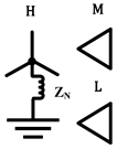
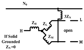
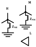
Similarly, the bank connection types of a three-winding transformer are shown in Table 3. As in the two-winding transformers, only the zero sequence differs according to the bank connection type. The relationship between the transformer topology and the zero-sequence connection discussed in this section affects the fault current contribution, as described in Section 3.

3. Impact of Interconnection Transformer Topology on Fault Current Contribution

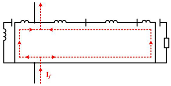
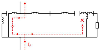
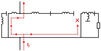
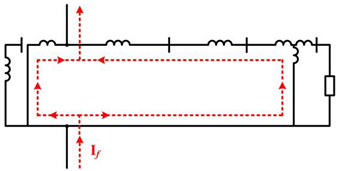
This section investigates how the interconnection transformer topology impacts the symmetric components of fault currents, especially zero-sequence fault currents. If the grid-side winding is not grounded, the zero-sequence fault currents cannot flow through the transformer to the fault location. Whether this zero-sequence component flows into the grid is closely related to the protection coordination, such as grounding coordination and relay settings. Hence, the interconnection transformer topology in power grids with DERs is critical from the protection perspective. The behaviors of the zero-sequence fault currents for the different transformer topologies are visualized in Table 4.
As described in Table 4, the transformers with the D-Yg, Y-D-Yg, or D-D-Yg topologies, which are not grounded at the grid side, prevent the zero-sequence fault currents of DER from flowing into the fault locations. This way, the interconnection transformer topology affects the zero-sequence fault current contribution of the DERs. Considering that IBDGs have a small fault current contribution, variations in the zero-sequence fault currents may confuse the operation of the protective relays.
Moreover, it can be analyzed similarly when a load is connected to the line. Most loads are connected to the system through the wye connection, but some loads are through the delta one. Note that in the sequence network, a wye-connected load is represented by positive-, negative-, and zero-sequence impedances. In contrast, a delta-connected load only has positive- and negative-sequence impedances, which affects fault analysis and relay operations. Despite the impact of the load topology, this study focuses on the transformer topology.

4. Investigation of Fault Behaviors of the IBDG

This section analyzes the differences in the fault analysis for each SBDG and IBDG. Although [26] describes the fault analysis with an SBDG only, this study analyzes a system with an IBDG and compares the two cases. The superposition principle is used for the fault analysis, and the IBDG has the same capacity as the SBDG for rigorous comparison.

4.1. Short-Circuit Analysis of the SBDG-Based System

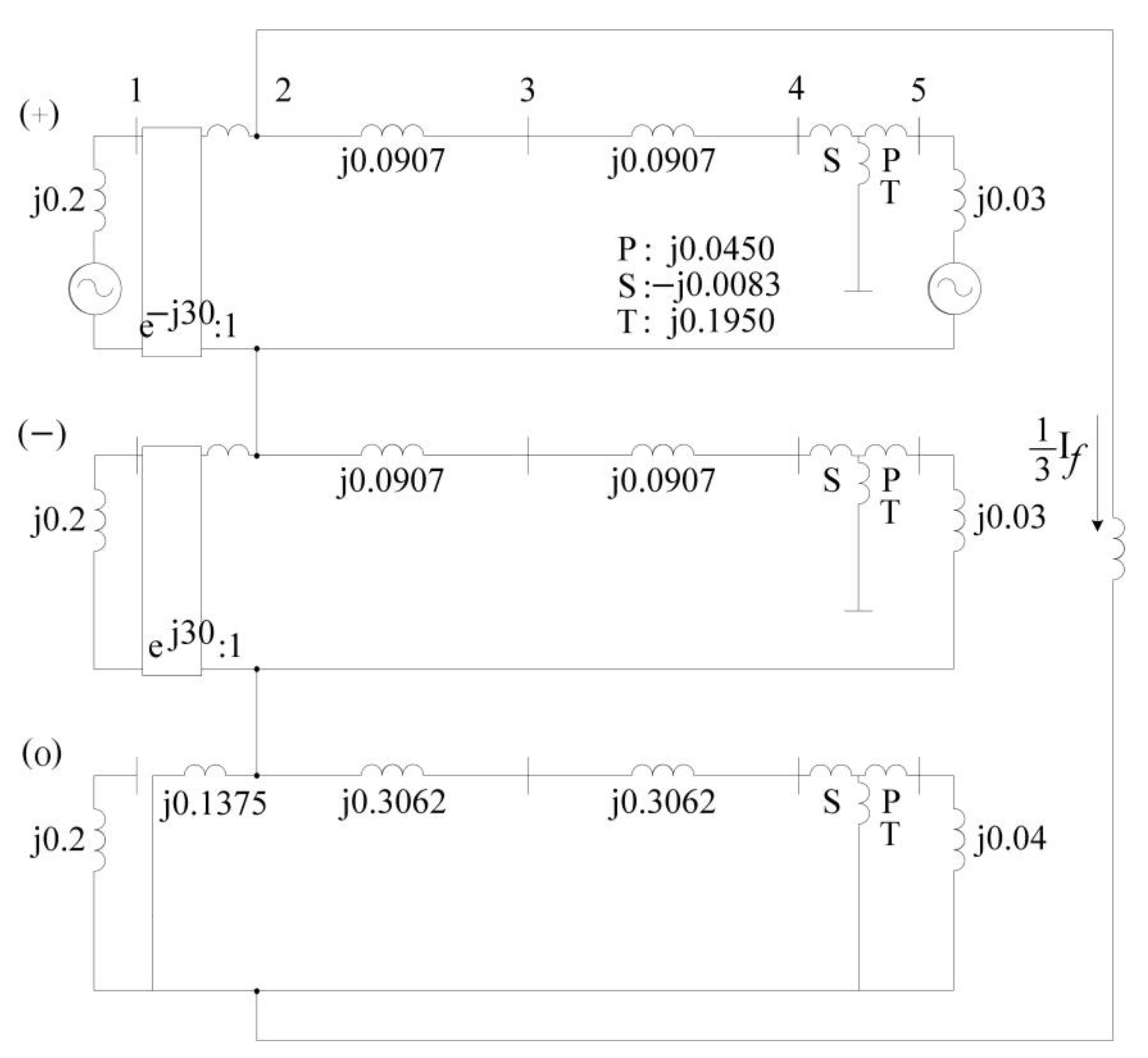
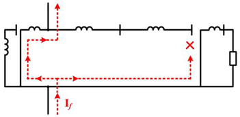
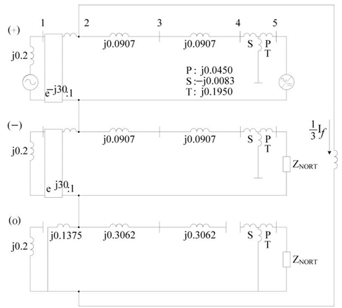
The test system analyzed in this study is shown in Figure 1. This study assumes that a fault occurs in the transmission line to observe how the DER contributes to the fault current. There exists a step-up transformer with a delta/Yg connection between buses 1 and 2. The high-voltage side carries 115 kV, and the low-voltage side on which a generator is connected carries 13.8 kV. There is also an interconnection transformer between buses 4 and 5, and its winding shape is Yg/Delta/Yg. Its high-voltage side, at which a DG is connected, is 230 kV, and the low-voltage side is 115 kV. Figure 2 represents the sequence networks of Figure 1, and Table 5 lists the model parameters of the test system.
As the single-line-to-ground (SLG) fault is on bus 2, the impedance observed by bus 2 is required for the short-circuit analysis. Hence, the Z bus matrix of the system needs to be constructed. Although the test system has five buses, as shown in Figure 1, the middle part of the three-winding transformer is, for convenience, viewed as a pseudo bus and becomes the sixth bus. The fifth column and row of the matrix components are assigned to the pseudo bus, and the sixth column and row refer to bus 5.
In general, the required impedance matrix can be obtained from Equations (1) and (2), and the fault impedance observed from bus 2, i.e., element (2, 2) of the matrix, is required for the analysis. Alternatively, the fault impedance can also be calculated, as shown in Equations (3) and (4).
Z ( B u s ) ( 1 ) = Z ( B u s ) ( 2 ) = [ 0.1317 i 0.0847 i 0.0537 i 0.0228 i 0.0256 i 0.0102 i 0.0847 i 0.1430 i 0.0907 i 0.0384 i 0.0432 i 0.0173 i 0.0537 i 0.0907 i 0.1151 i 0.0488 i 0.0548 i 0.0219 i 0.0228 i 0.0384 i 0.0488 i 0.0591 i 0.0665 i 0.0266 i 0.0256 i 0.0432 i 0.0548 i 0.0665 i 0.0654 i 0.0262 i 0.0102 i 0.0173 i 0.0219 i 0.0266 i 0.0262 i 0.0285 i ]
Z ( B u s ) ( 0 ) = [ 0.2000 i 0.0000 i 0.0000 i 0.0000 i 0.0000 i 0.0000 i 0.0000 i 0.1139 i 0.0613 i 0.0087 i 0.0102 i 0.0048 i 0.0000 i 0.0613 i 0.1978 i 0.0282 i 0.0328 i 0.0154 i 0.0000 i 0.0087 i 0.0282 i 0.0476 i 0.0554 i 0.0261 i 0.0000 i 0.0102 i 0.0328 i 0.0554 i 0.0548 i 0.0258 i 0.0000 i 0.0048 i 0.0154 i 0.0261 i 0.0258 i 0.0333 i ]
Z 22 ( 0 ) = X T 1 ( 0 ) / / { X T 2 T ( 0 ) / / ( X T 2 P ( 0 ) + X G 2 ( 0 ) ) + 2 × X L ( 0 ) + X T 2 S ( 0 ) } = 0.1139 90.00 °   p u
Z 22 ( 1 ) = Z 22 ( 2 ) = ( X G 1 ( 1 ) + X T 1 ( 1 ) ) / / ( 2 × X L ( 1 ) + X T 2 S ( 1 ) + X T 2 P ( 1 ) + X G 2 ( 1 ) ) = 0.1430 90.00 °   p u ,
where Z ( B u s ) ( 1 ) , Z ( B u s ) ( 2 ) , and Z ( B u s ) ( 0 ) are the impedance matrices of the positive, negative, and zero sequences, respectively. Z ( 22 ) ( 1 ) , Z ( 22 ) ( 2 ) , and Z ( 22 ) ( 0 ) are the positive-, negative-, and zero-sequence impedances observed from bus 2, respectively.
Using Equations (1)–(4), the fault current could be obtained as follows,
1 3 I f = ( V G 1 ( 1 ) + V G 2 ( 1 ) ) / ( Z 22 ( 1 ) + Z 22 ( 2 ) + Z 22 ( 0 ) ) = 2.4993 59.97 °   p u
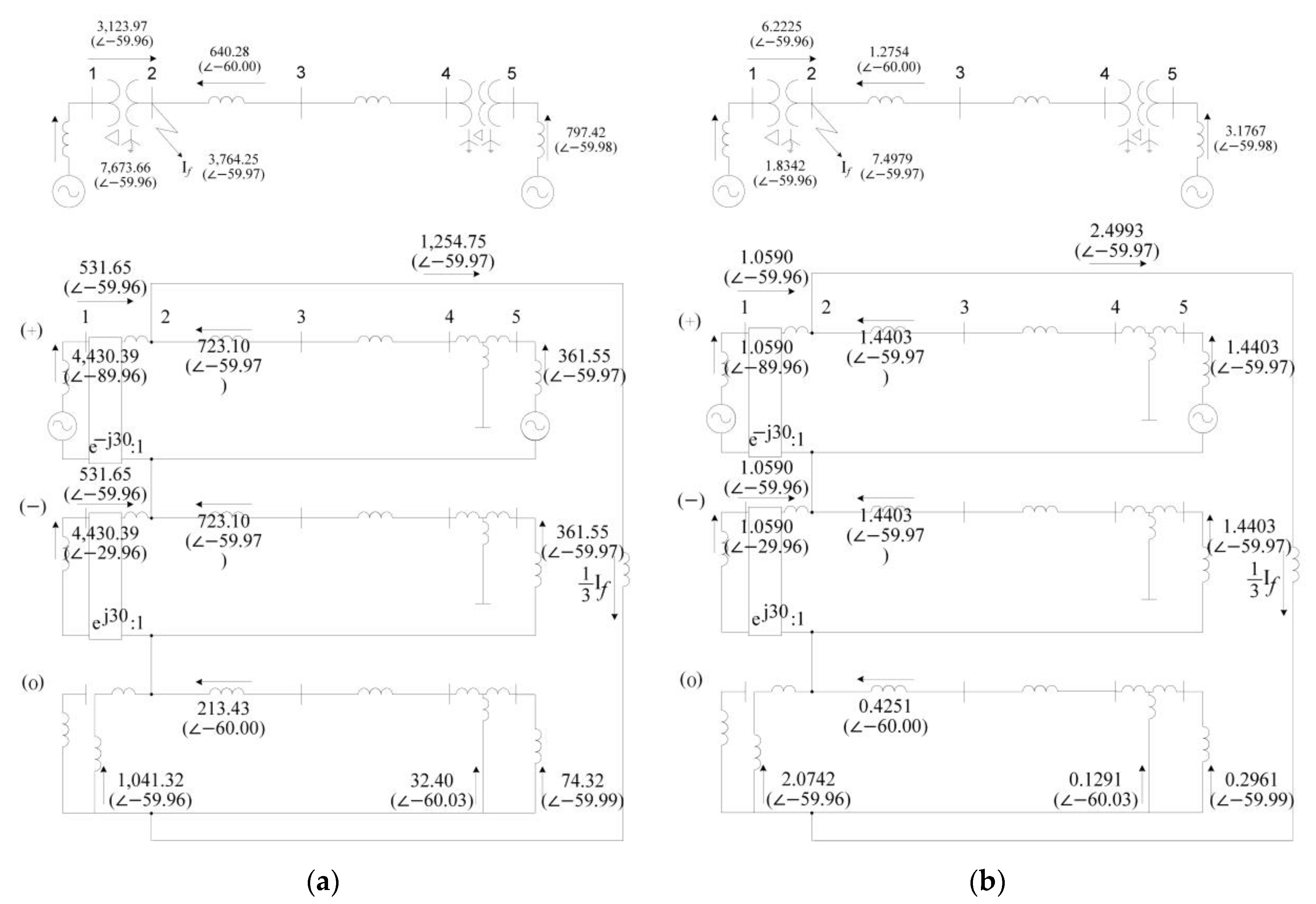
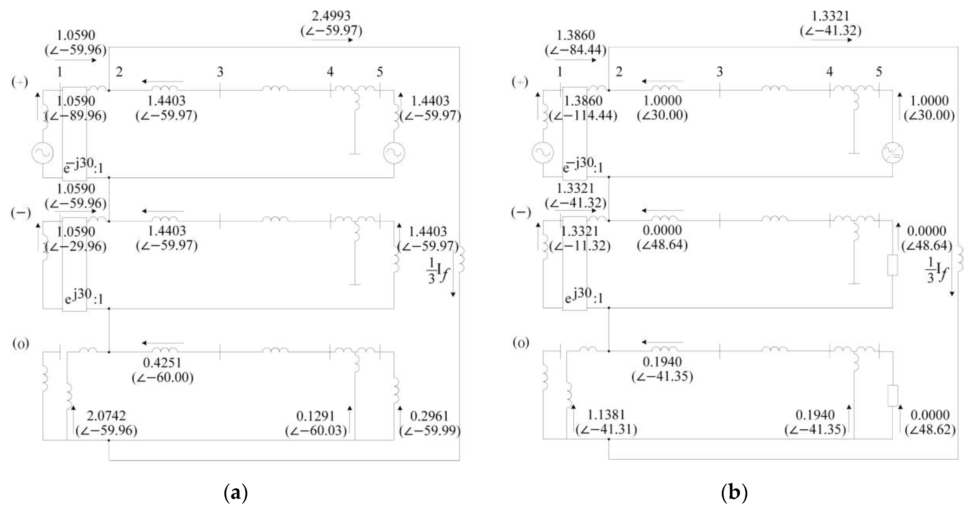
where If is the total fault current, and V G 1 ( 1 ) and V G 2 ( 1 ) are the positive-sequence voltage sources of G1 and G2, respectively. The symmetrical components of the fault current from bus 1 to bus 2 can be calculated based on the current division rule, thus yielding I 12 ( 0 ) = 2.0742 59.96 °   p u and I 12 ( 1 ) = I 12 ( 2 ) = 1.0590 59.96 °   p u , where I 12 ( 1 ) , I 12 ( 2 ) , and I 12 ( 0 ) are the positive-, negative-, and zero-sequence fault currents from bus 1 to 2, respectively. Similarly, the positive-, negative-, and zero-sequence fault currents from bus 3 to 2, which are denoted by I 32 ( 1 ) , I 32 ( 2 ) , and I 32 ( 0 ) , respectively, can be computed, yielding I 32 ( 0 ) = 0.4251 60.00 °   p u and I 32 ( 1 ) = I 32 ( 2 ) = 1.4403 59.97 °   p u . All these results are represented in Figure 3.

4.2. Short-Circuit Analysis of the IBDG-Based System

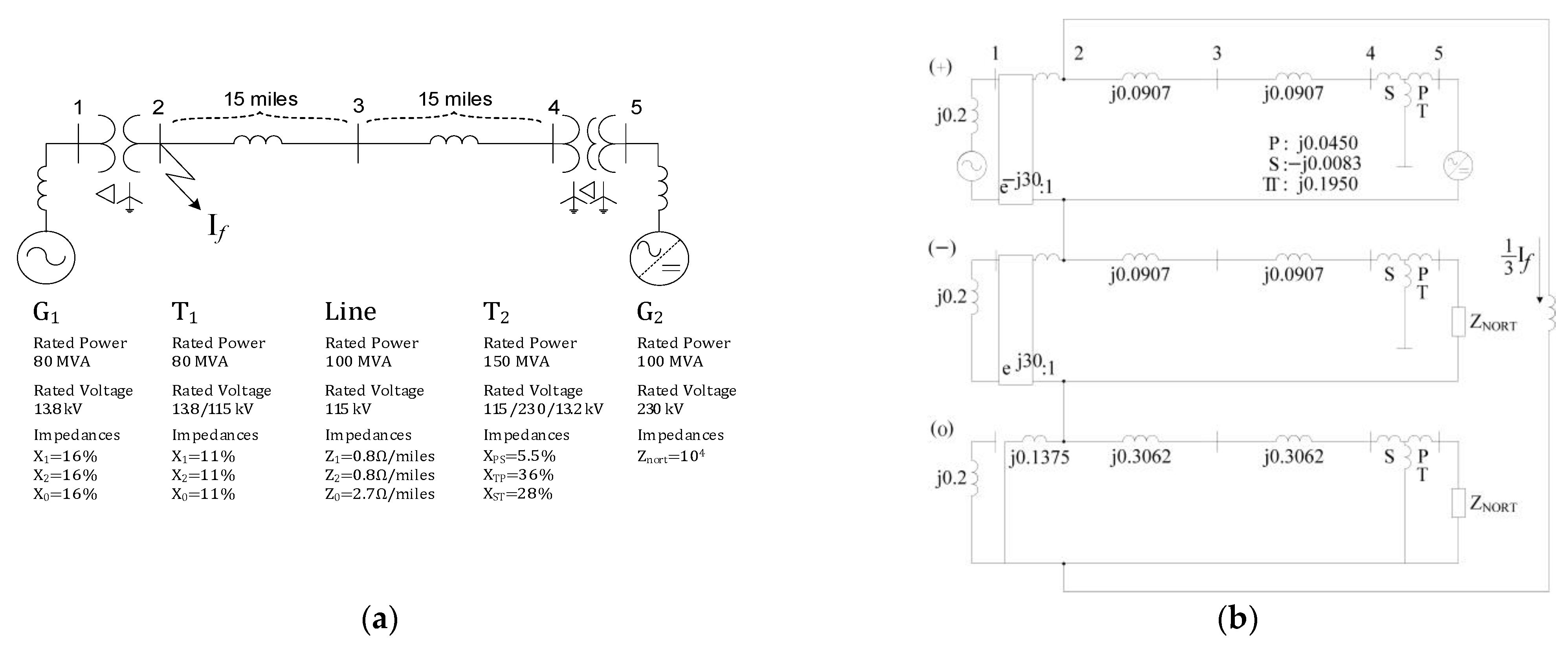
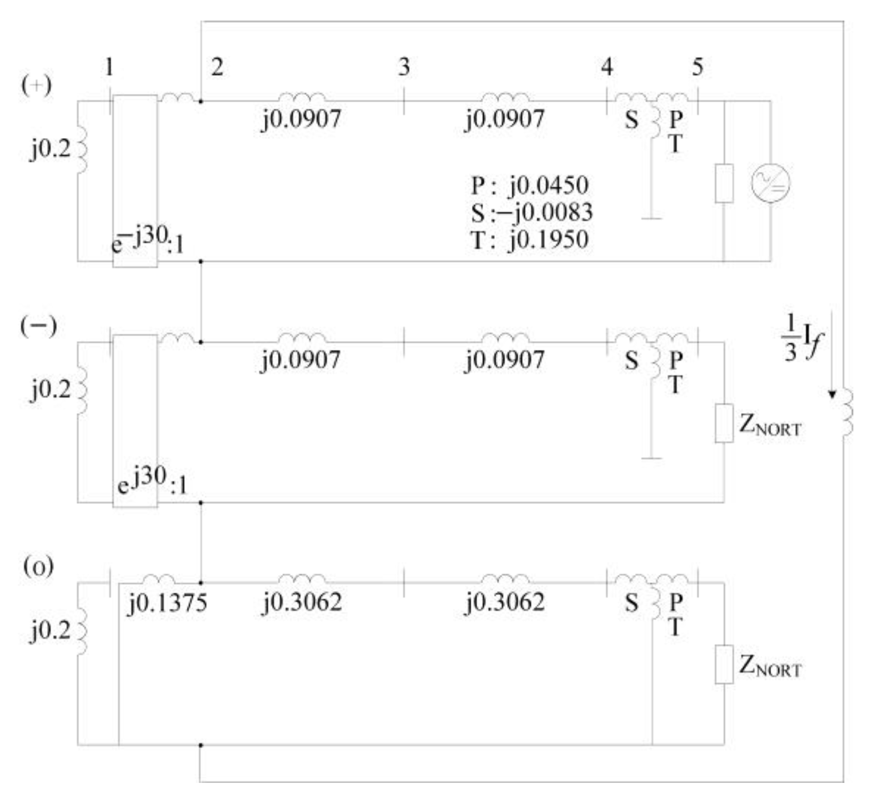
This section presents the fault analysis of the test system with an IBDG. The system model in Figure 4 is identical to that in Figure 2, where an IBDG is used instead of the SBDG. The rated power of the IBDG is 100 MVA, which is the same as that of the SBDG. The other system parameters are all the same, as shown in Figure 2. Table 6 lists the model parameters of the test system with the IBDG.

4.2.1. Decomposition and Short-Circuit Analysis: Voltage Source

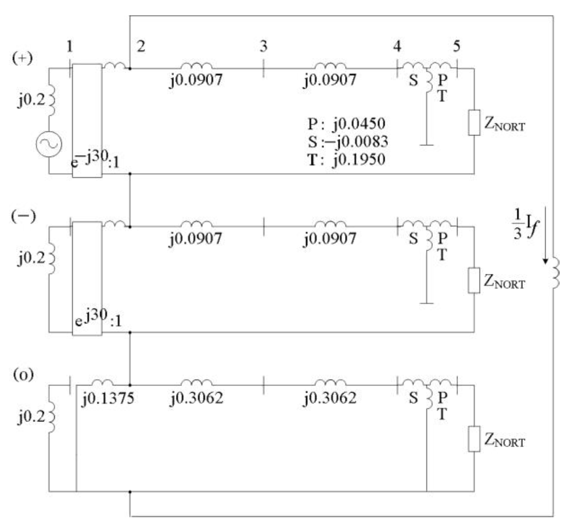
This section explains the superposition principle applied for the short-circuit analysis of the test system. Figure 4b can be decomposed into two circuits, wherein each circuit is excited by a voltage or a current source. Figure 5 represents a decomposed circuit with a voltage source observed only at the positive-sequence network. Note that there is a Norton equivalent impedance at each sequence network for the IBDG because IBDGs operate similarly to current sources in the steady state.
The procedure to compute the fault current is similar to that used for the cases with the SBDG. First, the Z bus matrix should be obtained. The Norton equivalent resistance is located between bus 5 and the ground, and its magnitude is set to 10 kΩ.
Z ( B u s ) ( 1 ) = Z ( B u s ) ( 2 ) = [ 0.2000 i 0.2000 i 0.2000 i 0.2000 i 0.2000 i 0.2000 i 0.2000 i 0.3375 i 0.3375 i 0.3375 i 0.3375 i 0.3375 i 0.2000 i 0.3375 i 0.4282 i 0.4282 i 0.4282 i 0.4282 i 0.2000 i 0.3375 i 0.4282 i 0.5189 i 0.5189 i 0.5189 i 0.2000 i 0.3375 i 0.4282 i 0.5189 i 0.5106 i 0.5106 i 0.2000 i 0.3375 i 0.4282 i 0.5189 i 0.5106 i 0.5556 i ]
Z ( B u s ) ( 0 ) = [ 0.2000 i 0.0000 i 0.0000 i 0.0000 i 0.0000 i 0.0000 i 0.0000 i 0.1173 i 0.0724 i 0.0274 i 0.0286 i 0.0286 i 0.0000 i 0.0724 i 0.2335 i 0.0884 i 0.0924 i 0.0924 i 0.0000 i 0.0274 i 0.0884 i 0.1495 i 0.1561 i 0.1561 i 0.0000 i 0.0286 i 0.0924 i 0.1561 i 0.1544 i 0.1544 i 0.0000 i 0.0286 i 0.0924 i 0.1561 i 0.1544 i 0.1994 i ]
Z 22 ( 0 ) = X T 1 ( 0 ) / / { X T 2 T ( 0 ) / / ( X T 2 P ( 0 ) + Z G 2 ( 0 ) ) + 2 × X L ( 0 ) + X T 2 S ( 0 ) } = 0.1173 90.00 °   p u
Z 22 ( 1 ) = Z 22 ( 2 ) = ( X G 1 ( 1 ) + X T 1 ( 1 ) ) / / ( 2 × X L ( 1 ) + X T 2 S ( 1 ) + X T 2 P ( 1 ) + Z G 2 ( 1 ) ) = 0.3375 90.00 °   p u
where Z ( B u s ) ( 1 ) , Z ( B u s ) ( 2 ) , and Z ( B u s ) ( 0 ) are the impedance matrices of the positive, negative, and zero sequences, respectively. Z ( 22 ) ( 1 ) , Z ( 22 ) ( 2 ) , and Z ( 22 ) ( 0 ) are the positive-, negative-, and zero-sequence impedances observed from bus 2, respectively.
Using Equations (6)–(9), the fault current could be obtained as follows,
1 3 I f = V G 1 ( 1 ) / ( Z 22 ( 1 ) + Z 22 ( 2 ) + Z 22 ( 0 ) ) = 1.2621 60.00 °   p u
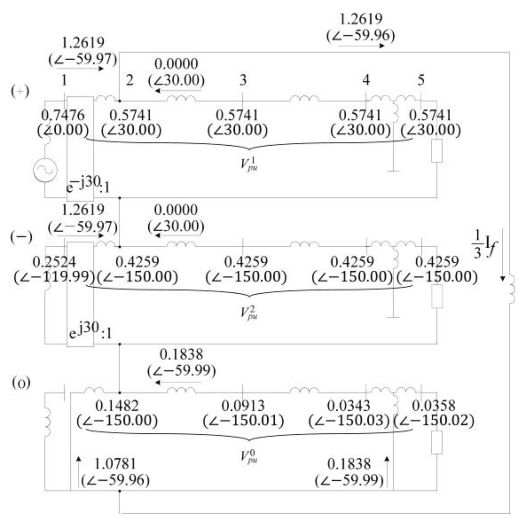
where If is the total fault current, and V G 1 ( 1 ) and V G 2 ( 1 ) are the positive-sequence voltage sources of G1 and G2, respectively. The symmetrical components of the fault current from bus 1 to bus 2 can be calculated based on the current division rule, thus yielding I 12 ( 0 ) = 1.0781 59.96 °   p u and I 12 ( 1 ) = I 12 ( 2 ) = 1.2619 59.97 °   p u , where I 12 ( 1 ) , I 12 ( 2 ) , and I 12 ( 0 ) are the positive-, negative-, and zero-sequence fault currents from bus 1 to 2, respectively.
Similarly, the current from bus 3 to 2 can be calculated, as shown in Figure 6. It can be observed from Figure 6 that there is a minor fault current contribution from the IBDG side.

4.2.2. Decomposition and Short-Circuit Analysis: Current Source

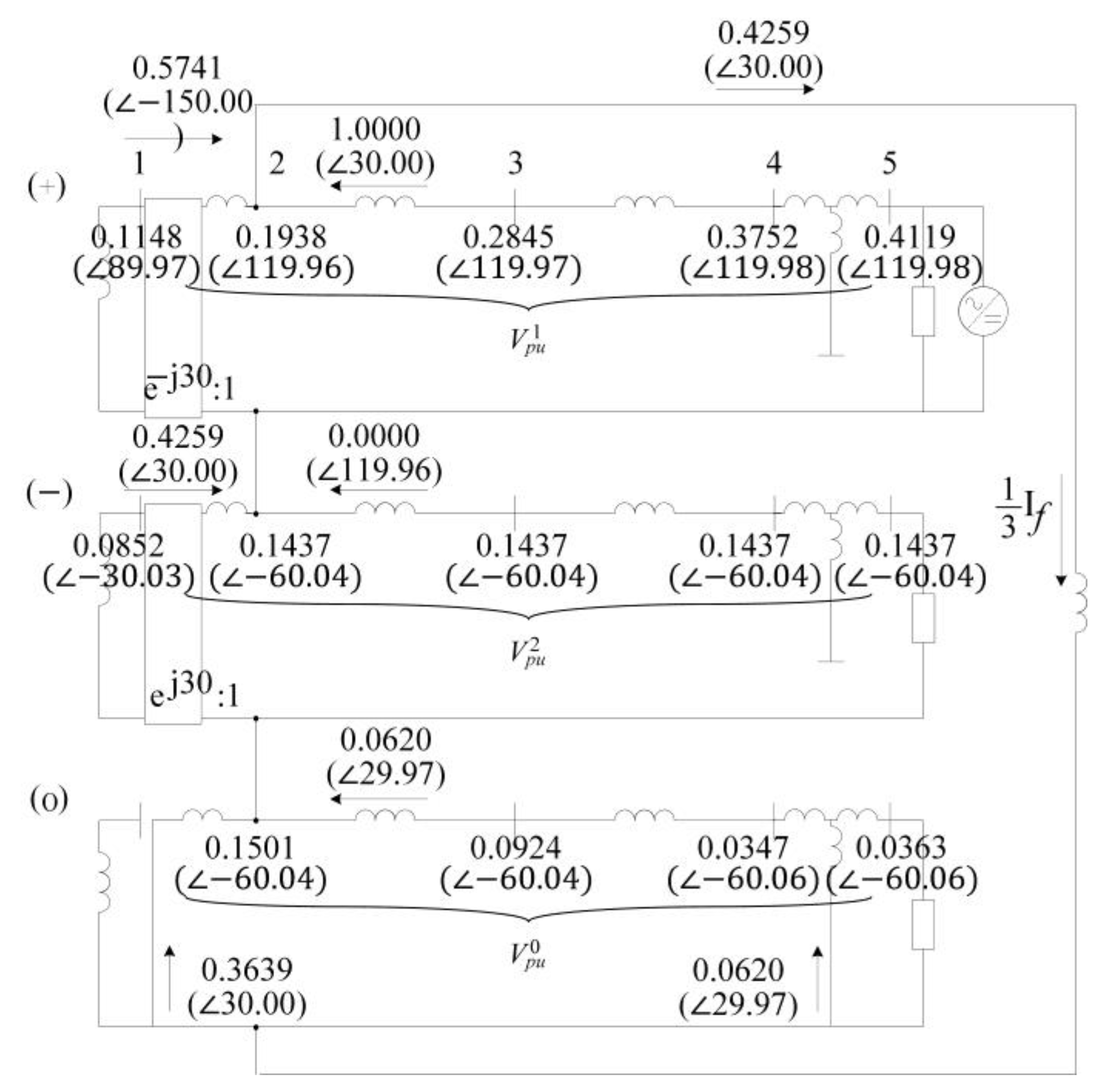
Figure 7 shows the sequence equivalent circuit of the decomposed circuit based on the current source, an IBDG. The current source can be observed in the positive sequence, and the other parameters are the same as in Figure 5.
The fault current of the current source is divided into two sides: one flows to bus 2, the fault location, and the other flows to the zero/negative-sequence circuit. The positive-sequence fault current from bus 1 is calculated. By subtracting the result from the total fault current, the zero/negative-sequence current can be obtained. As the rated power of the IBDG is 100 MVA, the current in the positive-sequence equivalent circuit is 1.0 pu. As the current source is the only source in the sequence equivalent circuit, it can be assumed that the fault current from the IBDG has the same magnitude as the rated current. As a result, the fault current supplied to the fault point is obtained by subtracting the current flowing from bus 1 to 2, I 12 ( 1 ) , from the total current, I t o t a l .
I 12 ( 1 ) = ( Z 22 ( 2 ) + Z 22 ( 0 ) ) / ( X G 1 ( 1 ) + X T 1 ( 1 ) + Z 22 ( 2 ) + Z 22 ( 0 ) ) × 1 150.00 ° = 0.5740 150.00 °   p u
I t o t a l I 12 ( 1 ) = 1.0 150.00 ° 0.5740 150.00 ° = 0.4259 30.00 °   p u
The fault currents of the zero- and negative-sequence networks can be obtained using the current division rule, and the results are shown in Figure 8.

4.2.3. Superposition

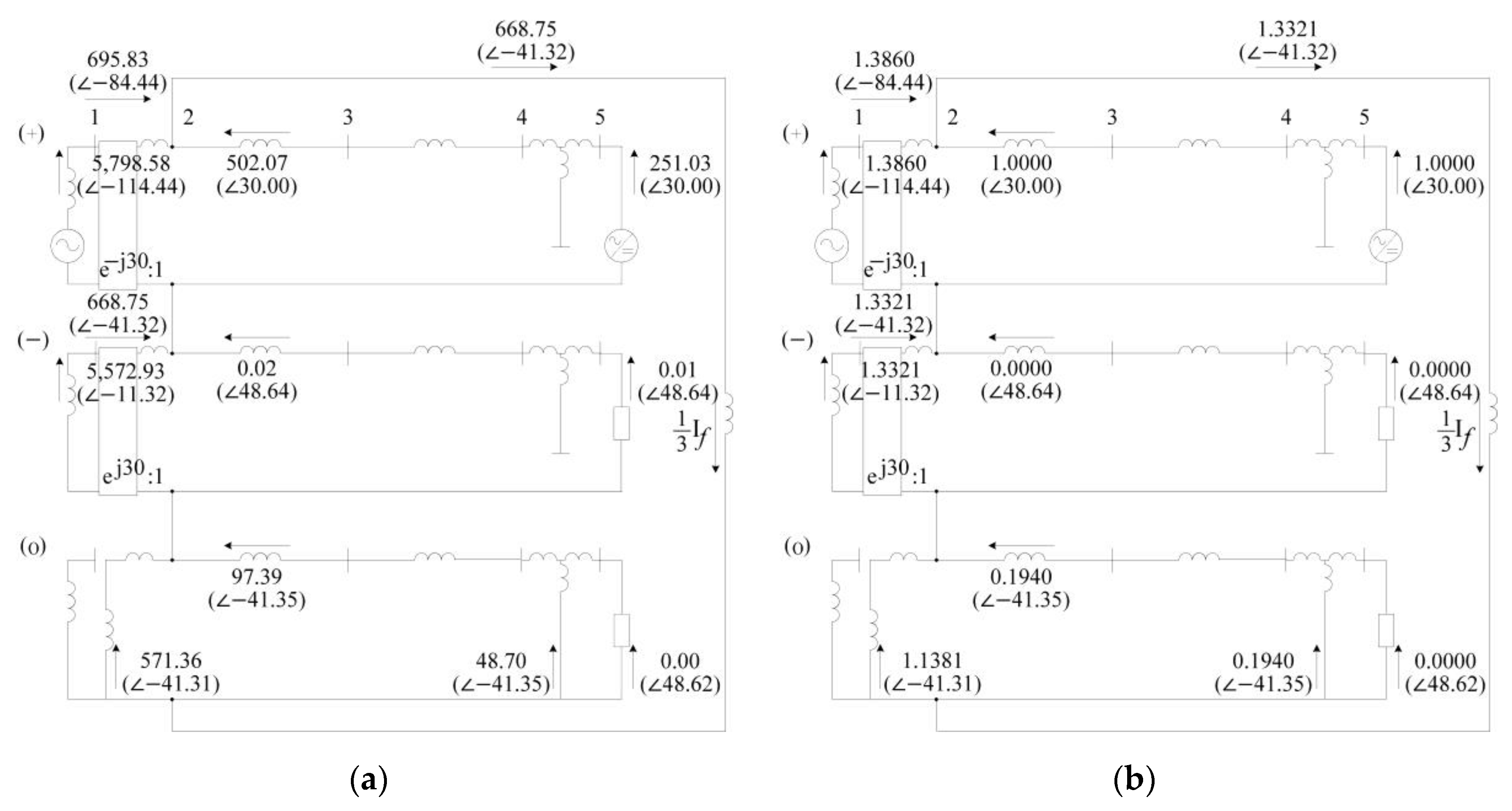
As shown in Figure 6 and Figure 8, the results of each source are superposed according to the superposition principle. As a result, Figure 9 describes the superposed fault current.
For a more detailed analysis, the detailed voltage and current values of the system model with an IBDG are considered. Table 7 lists all the voltages in the superposed circuit.
Given the SLG on phase A, the phase-A voltage at bus 2 is zero. Note that more attention should be paid to the current magnitude in terms of the system fault and its protection coordination. In this manner, the currents flowing between the buses and transmitted to the fault point are listed in Table 8.
The current flowing from bus 2 to the point of failure is the total fault current. The phase-A current has a relatively large value, whereas the phase-B and -C currents have almost zero values. The IBDG impact analysis must consider the magnitude of the current flowing from bus 3 to 2, which indicates the IBDG’s fault current contribution. It can be observed that the values are either zero or very small, especially for the zero and negative sequences. These zero or small values are attributed to the fact that the Norton equivalent resistance in the IBDG model, which has a very large value compared with the line impedance, is inserted in the sequence equivalent circuit. This fact has two implications for us. First, according to the interconnection transformer of the IBDG winding method, the effect of the fault current may vary because the zero-sequence equivalent circuit of the transformer has a different shape depending on the winding method. Depending on whether the fault current flows through the zero-sequence network, the fault effect may vary. Second, the IBDG’s negative-sequence fault current has a small value owing to the high value of Norton’s equivalent resistance, thus indicating that changes are needed in the setting values of the protective relays; these currently rely on negative-sequence fault currents. In this study, the test system and the DG are connected through a three-winding transformer with a winding of Yg/D/Yg. As a result, the zero-sequence currents from the DG circulate in the delta windings. Overall, the fault effects of DGs may vary depending on the winding method.

4.3. Comparison of the SBDG and IBDG Cases

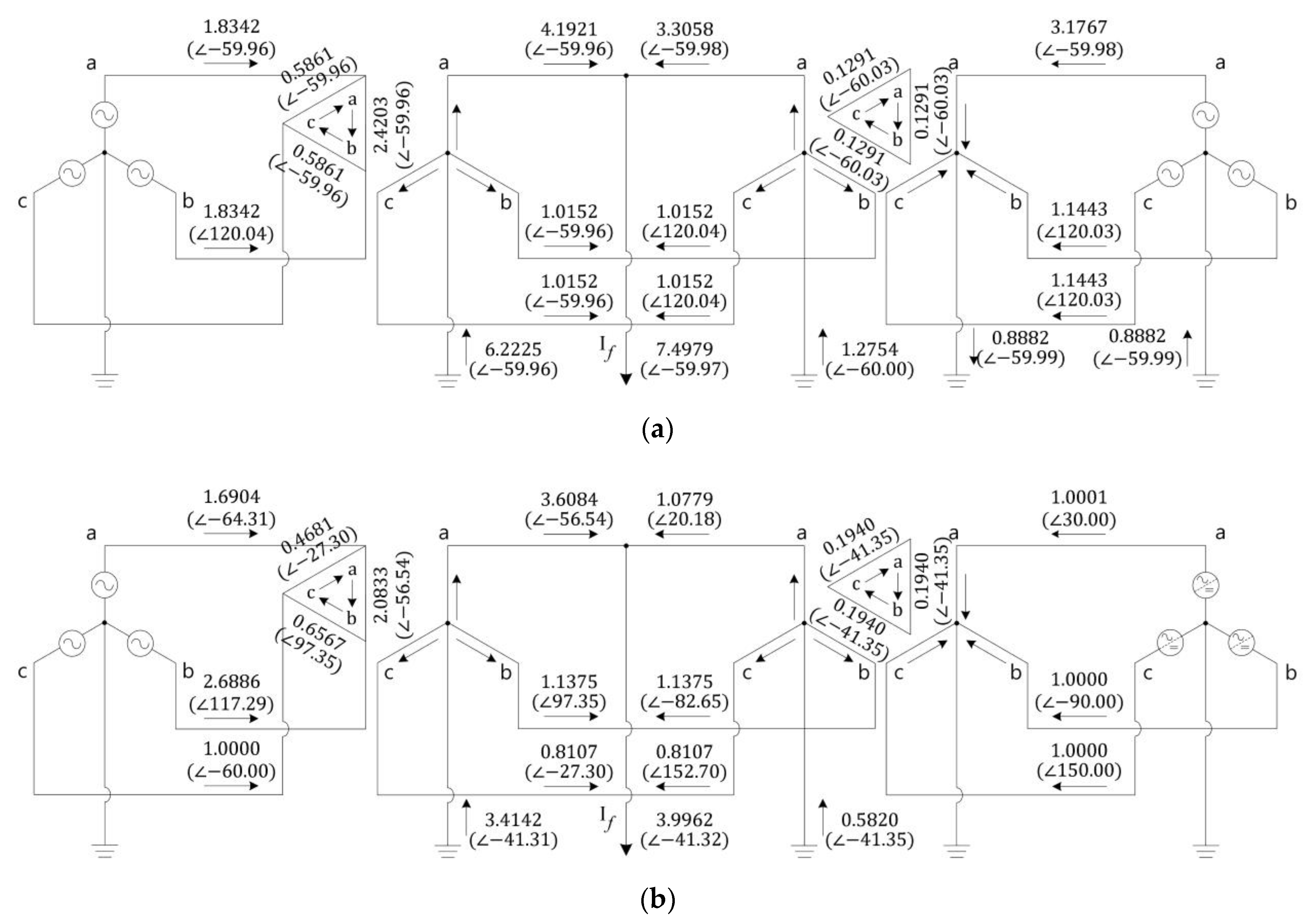
For the comparison of the fault contributions of the SBDG and IBDG, their results are shown in Figure 10. The direction and number of arrows indicate the current flow and magnitude, respectively.
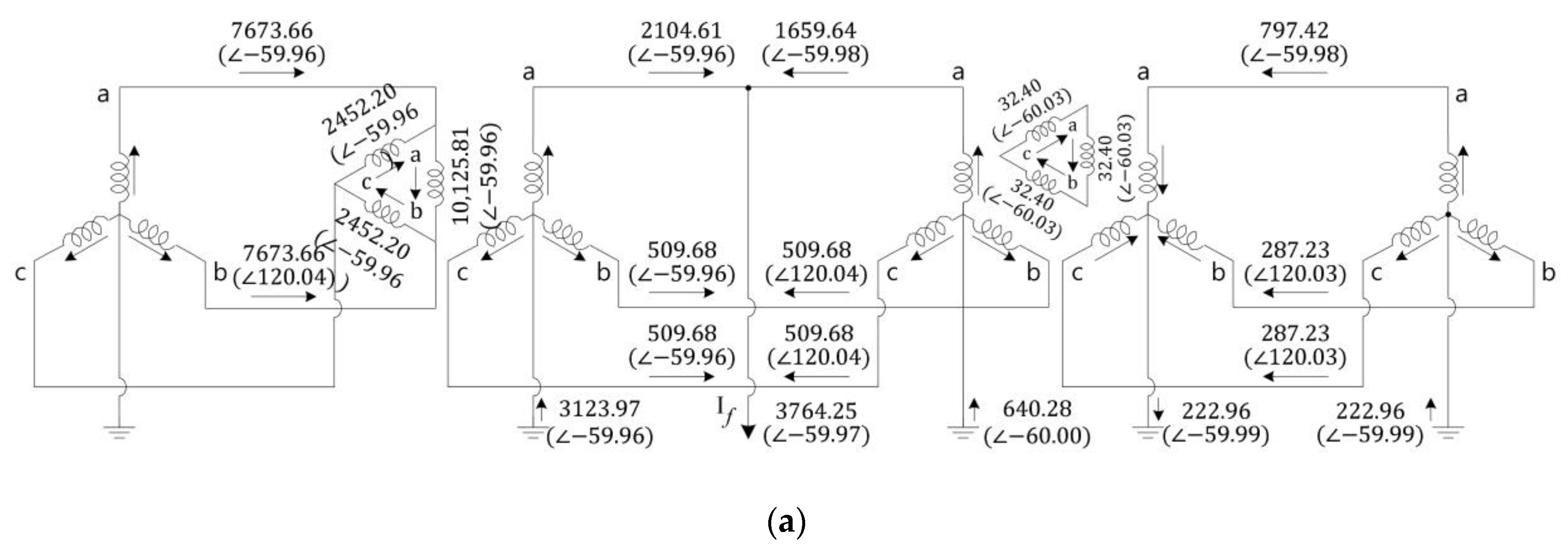
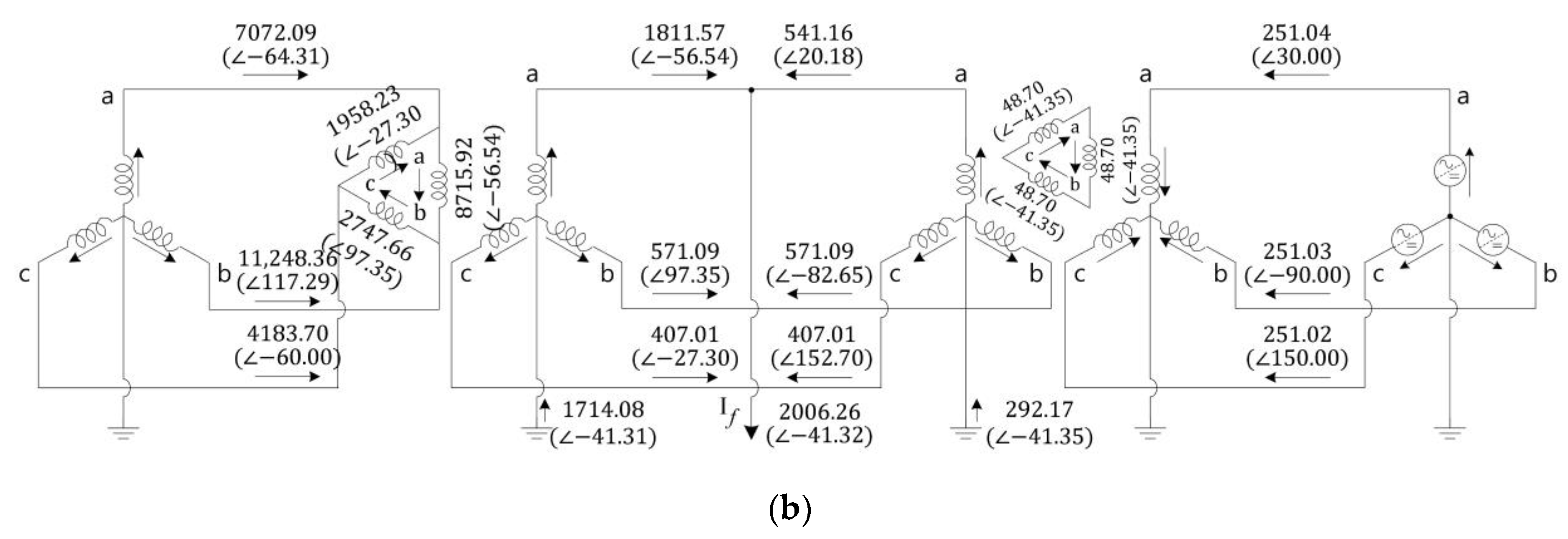
It can be concluded that the fault current of the IBDG is smaller than that of the SBDG. As mentioned earlier, the IBDG operates similarly to a current source at the steady state. Thus, the magnitude of the fault current is limited. In addition, the negative- and zero-sequence circuits of the IBDG show that the corresponding fault current is zero or very small. It can also be observed that the Norton equivalent resistance is large enough to block the fault current. Figure 11 shows the currents in the ABC networks in pu. For the engineers who deal with practical systems, the results expressed in amperes are also shown in Figure 12. The figures also clearly show the calculations of the fault current of the three-winding transformer.

4.4. Accuracy Test

The previous sections established a fault analysis method in the system, wherein the IBDG was connected, and compared the analyzed results with those of the SBDG case. For the accuracy test, the same simulation was conducted through PSCAD/EMTDC, a commercial electromagnetic transient analysis program. The delta side of G1 lags the Y side, and the fault occurs at 0.5 s. The resulting values are converted to positive-, negative-, and zero-sequence values in PSCAD/EMTDC. The transmission lines are modeled using pi sections, and their resistances and capacitances are not zero but have marginal values, which cause a slight error. However, these errors are insignificant. The accuracy of the short-circuit analysis performed in this study is validated, as indicated in Table 9.
Table 10 compares the results of the short-circuit analysis, which is implemented using MATLAB and PSCAD/EMTDC. The differences during the SLG fault are 0.52%, 0.46%, and 0.72% at buses 2, 3, and 4, respectively. The errors are mainly due to the nonzero resistance of the transmission lines in PSCAD/EMTDC. Thus, it is concluded that the approach presented in this study can analyze the contributions of IBDGs with high accuracy.

5. Short-Circuit Analysis with Consideration of the Interconnection Transformer

5.1. Case Study with Different Topologies of the Interconnection Transformer

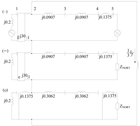
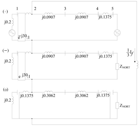
This section presents short-circuit analyses with the different topologies of the interconnection transformer. In Section 4, an interconnection transformer, expressed by T2, had two grounded Y windings at the primary and secondary sides and a delta winding at the tertiary side (i.e., Yg-D-Yg). This section compares its results with those of the different topologies, D-Yg, Yg-D, Y-D-Yg, and D-D-Yg. As explained in Section 2, transformers with different topologies only differ in the zero-sequence network. Table 11 shows the sequence networks of a transformer with Y-D-Yg or D-D-Yg topologies interconnected on the DG side. The two topologies result in the same outcomes. In the case of the two-winding transformers, the same impedances of Generator 1 are used in the analysis. Note that the higher voltage side is the DG side.
The short-circuit can be analyzed through the sequence network equivalent circuits presented above. The zero sequence of the D-Yg transformer provides no path for the fault current from the DG bus, and therefore, the zero-sequence fault current has a very small value. The results of the D-Yg topology are presented in Table 12 and Table 13. Note that the D-Yg transformer in this section indicates a Dy1 transformer with grounding. The other types of Dy transformers, such as Dy11, show results similar to the D-Yg transformer case except for the phase shifts.
Contrary to the sequence network of the D-Yg transformer, the zero sequence of the Yg-D transformer provides a path for the fault current from the DG bus. Hence, the zero-sequence fault current is larger than the D-Yg transformer. The results of the Yg-D topology are presented in Table 14 and Table 15. Note that the Yg-D transformer in this section implies the Yd1 transformer with grounding. When testing with the Yd11 transformer, which is another type of Yd transformer, the results are almost the same as those of the Yd1 case except for the phase shifts.
The voltages and currents of the transformer with the Y-D-Yg or D-D-Yg topologies are almost identical to those of the Yg-D-Yg transformer. The only difference in the sequence equivalent circuit is that there is only one path in which a zero-sequence current can flow, thus resulting in a smaller fault current magnitude than that in the Yg-D-Yg topology case. Hence, the setting values of protective devices should be set by considering the negative injection owing to the interconnection transformer for protection coordination and relaying. The results of the Y-D-Yg topology and D-D-Yg topologies are listed in Table 16 and Table 17.
Most grid codes for DER interconnection require DER grounding to ensure the magnitude of the fault current and to suppress transient overvoltage. These requirements are called grounding coordination or effective grounding. Thus, to evaluate grounding coordination, it is essential to analyze the transformer topology and the fault current. In particular, if the connected transformer does not provide sufficient grounding, a grounding source may need to be installed through a separate grounding transformer such as a zig-zag transformer.

5.2. Case Study Analyses

It can also be noted that the contributions of the zero-sequence fault currents from the DERs impact the total fault currents. In the case of the two-winding transformers, the Yg-D transformer topology, which is grounded at the grid side, yields a larger total fault current (i.e., 4.0218 ∠−41.35° pu) than the D-Yg transformer (i.e., 3.8970 ∠−41.35° pu), which is not grounded at the grid side. This difference is primarily because the zero-sequence fault current contributes to the total fault current, which can also be observed in the three-winding transformers. That is, the total fault current of the Yg-D-Yg transformer (i.e., 3.9962 ∠−41.32° pu) is slightly larger than that of the Y-D-Yg or D-D-Yg transformers (i.e., 3.8970 ∠−41.35° pu). It should be noted that if the transformer was grounded at the DER side and not at the grid side, the total fault currents of the two- and three-winding transformers would be identical to each other.
In the end, the grounding and topology of the interconnection transformer of the DER should be considered for short-circuit analyses. Therefore, many grid codes state that DER systems must adhere to the same transformer grounding design as the general electric power systems. However, the interconnection transformer grounded at the grid side could increase the zero-sequence current during normal operation, which may compromise the security of the protective relays, such as overcurrent ground relays. In other words, the overcurrent ground relays may trip because of the zero-sequence current contribution from the DERs even when no faults occur. In addition to the malfunctioning of the relay, the zero-sequence current may increase the loss in the neutral line. This issue should be addressed in future research studies.

6. Conclusions

To assess the impact of IBDGs as distribution systems that have yet to be fully prepared for connecting renewable energy sources, this study analyzed the fault current contributions of IBDGs with the extensively used model and explained the failure analysis of IBDGs more intuitively by presenting IBDG fault analysis with a model familiar to engineers or researchers. Moreover, this study will give them a better understanding of the fault analyses of systems with IBDGs. The case study evaluated herein covered a single DER, thus making it clear that the analysis approach can also be applied to multiple DERs if their models and parameters are known. In other words, the circuits of DERs can be modeled and then integrated into the main circuit in parallel. After implementing the short-circuit analysis for each source or DER, the results can be combined using the superposition principle. From this fault analysis, it is observed that the IBDG’s fault current is smaller than that of the SBDG, and the reason is that the IBDG operates as a current source, thereby limiting the magnitude of the fault current of IBDGs. In addition, the analysis also indicated that the topology of interconnection transformers should be considered because negative- and zero-sequence fault currents can be generated.
However, this approach cannot observe dynamic behavior in transience when a fault occurs. This transient analysis requires detailed models of inverters, which differ by manufacturers or control algorithms, and time-domain simulations based on dynamic models. This analysis remains for further study.

Author Contributions

Conceptualization, N.C.; methodology, N.C.; software, N.C. and M.Y.; validation, M.Y. and S.C.; formal analysis, M.Y.; investigation, M.Y.; resources, N.C.; data curation, M.Y.; writing—original draft preparation, N.C., M.Y. and S.C.; writing—review and editing, N.C. and S.C.; visualization, M.Y.; supervision, N.C. and S.C.; project administration, N.C. and S.C.; funding acquisition, N.C. and S.C. All authors have read and agreed to the published version of the manuscript.

Funding

This research was supported in part by the Korea Electric Power Corporation (No. R20DA33), in part by the Basic Research Program through the National Research Foundation of Korea (NRF) funded by the MSIT (No. 2020R1A4A1019405), and in part by the National Research Foundation of Korea (NRF) grant funded by the Korea government (MSIT) (No. 2022R1A2C2011522).

Institutional Review Board Statement

Not applicable.

Informed Consent Statement

Not applicable.

Data Availability Statement

Not applicable.

Conflicts of Interest

The authors declare no conflict of interest.

Abbreviations

DERDistributed energy resource
SBDGSynchronous-based distributed generation
IBDGInverter-based distributed generation
DGDistributed generation
SLGSingle-line-to-ground

References

  1. D’Adamo, I.; Rosa, P. Current state of renewable energies performances in the European Union: A new reference framework. Energy Convers. Manag. 2016, 121, 84–92. [Google Scholar] [CrossRef]
  2. Pinson, P.; Mitridati, L.; Ordoudis, C.; Østergaard, J. Towards fully renewable energy systems: Experience and trends in Denmark. CSEE J. Power Energy Syst. 2017, 3, 26–35. [Google Scholar] [CrossRef]
  3. Marafao, F.P.; Alonso, A.M.D.S.; Goncalves, F.A.S.; Brandao, D.I.; Martins, A.C.G.; Paredes, H.K.M. Trends and constraints on Brazilian photovoltaic industry: Energy policies, interconnection codes, and equipment certification. IEEE Trans. Ind. Applicat. 2018, 54, 4017–4027. [Google Scholar] [CrossRef]
  4. Holdmann, G.P.; Wies, R.W.; Vandermeer, J.B. Renewable energy integration in Alaska’s remote islanded microgrids: Economic drivers, technical strategies, technological Niche development, and policy implications. Proc. IEEE 2019, 107, 1820–1837. [Google Scholar] [CrossRef]
  5. Ozarisoy, B.; Altan, H. Developing an evidence-based energy-policy framework to assess robust energy-performance evaluation and certification schemes in the South-eastern Mediterranean countries. Energy Sustain. Develop. 2021, 64, 65–102. [Google Scholar] [CrossRef]
  6. Burke, M.J.; Stephens, J.C. Energy democracy: Goals and policy instruments for sociotechnical transitions. Energy Res. Soc. Sci. 2017, 33, 35–48. [Google Scholar] [CrossRef]
  7. Abrishambaf, O.; Lezama, F.; Faria, P.; Vale, Z. Towards transactive energy systems: An analysis on current trends. Energy Strategy Rev. 2019, 26, 100418. [Google Scholar] [CrossRef]
  8. Bayer, B.; Matschoss, P.; Thomas, H.; Marian, A. The German experience with integrating photovoltaic systems into the low-voltage grids. Renew. Energy 2018, 119, 129–141. [Google Scholar] [CrossRef]
  9. Kennedy, J.; Ciufo, P.; Agalgaonkar, A. A review of protection systems for distribution networks embedded with renewable generation. Renew. Sustain. Energy Rev. 2016, 58, 1308–1317. [Google Scholar] [CrossRef] [Green Version]
  10. Manditereza, P.T.; Bansal, R. Renewable distributed generation: The hidden challenges—A review from the protection perspective. Renew. Sustain. Energy Rev. 2016, 58, 1457–1465. [Google Scholar] [CrossRef]
  11. Sidhu, T.S.; Bejmert, D. Short-circuit current contribution from large scale PV power plant in the context of distribution power system protection performance. In Proceedings of the IET Conference on Renewable Power Generation (RPG 2011), Edinburgh, UK, 6–8 September 2011; pp. 1–6. [Google Scholar] [CrossRef]
  12. IEEE 1547.2-2008; IEEE Application Guide for IEEE std 1547(TM), IEEE Standard for Interconnecting Distributed Resources with Electric Power Systems. IEEE: New York, NY, USA, 2009. [CrossRef]
  13. Popadic, B.; Dumnic, B.; Strezoski, L. Modeling of initial fault response of inverter-based distributed energy resources for future power system planning. Int. J. Electr. Power Energy Syst. 2020, 117, 105722. [Google Scholar] [CrossRef]
  14. Haj-Ahmed, M.A.; Illindala, M.S. The influence of inverter-based DGs and their controllers on distribution network protection. IEEE Trans. Ind. Applicat. 2014, 50, 2928–2937. [Google Scholar] [CrossRef]
  15. Haddadi, A.; Zhao, M.; Kocar, I.; Karaagac, U.; Chan, K.W.; Farantatos, E. Impact of inverter-based resources on negative sequence quantities-based protection elements. IEEE Trans. Power Deliv. 2020, 36, 289–298. [Google Scholar] [CrossRef]
  16. Behnke, M.R.; Custer, G.; Farantatos, E.; Fischer, N.; Guttromson, R.; Isaacs, A.; Majumder, R.; Pant, S.; Patel, M.; Venkat, R.-K.; et al. Impact of Inverter-Based Resource Negative-Sequence Current Injection on Transmission System Protection; United States Department of Energy: Oak Ridge, TN, USA, 2020. [Google Scholar]
  17. Saleh, K.A.; Zeineldin, H.H.; Al-Hinai, A. A three-phase fault currents calculation method used for protection coordination analysis. In Proceedings of the 2014 IEEE PES T&D Conference and Exposition, Chicago, IL, USA, 14–17 April 2014; pp. 1–5. [Google Scholar] [CrossRef]
  18. Kou, G.; Jordan, J.; Cockerham, B.; Patterson, R.W.; VanSant, P. Negative-sequence current injection of transmission solar farms. IEEE Trans. Power Deliv. 2020, 35, 2740–2743. [Google Scholar] [CrossRef]
  19. Erlich, I.; Neumann, T.; Shewarega, F.; Schegner, P.; Meyer, J. Wind turbine negative sequence current control and its effect on power system protection. In Proceedings of the 2013 IEEE Power & Energy Society General Meeting, Vancouver, BC, Canada, 21–25 July 2013; pp. 1–5. [Google Scholar] [CrossRef]
  20. Liu, X. Fault current negative contribution method for inverter-based distributed generators under grid unbalanced fault. IEEE Access 2020, 8, 220807–220815. [Google Scholar] [CrossRef]
  21. Rajaei, N.; Ahmed, M.H.; Salama, M.M.A.; Varma, R.K. Analysis of fault current contribution from inverter based distributed generation. In Proceedings of the 2014 IEEE PES General Meeting|Conference & Exposition, National Harbor, MD, USA, 27–31 July 2014; pp. 1–5. [Google Scholar] [CrossRef]
  22. Kim, I. A calculation method for the short-circuit current contribution of current-control inverter-based distributed generation sources at balanced conditions. Electr. Power Syst. Res. 2021, 190, 106839. [Google Scholar] [CrossRef]
  23. Mathur, A.; Das, B.; Pant, V. Fault analysis of unbalanced radial and meshed distribution system with inverter based distributed generation (IBDG). Int. J. Electr. Power Energy Syst. 2017, 85, 164–177. [Google Scholar] [CrossRef]
  24. Kim, I. Short-circuit analysis models for unbalanced inverter-based distributed generation sources and loads. IEEE Trans. Power Syst. 2019, 34, 3515–3526. [Google Scholar] [CrossRef]
  25. Li, Y.; Wang, D. A fast fault current calculation method for distribution networks connected with inverter interfaced distributed generators. MethodsX 2021, 8, 101176. [Google Scholar] [CrossRef]
  26. Blackburn, J.L.; Domin, T.J. Protective Relaying—Principles and Applications, 4th ed.; CRC Press LLC: Boca Raton, FL, USA, 2014. [Google Scholar]
  27. Cho, N.; Yun, S.; Jung, J. Shunt fault analysis methodology for power distribution networks with inverter-based distributed energy resources of the Korea Electric Power Corporation. Renew. Sustain. Energy Rev. 2020, 133, 110–140. [Google Scholar] [CrossRef]
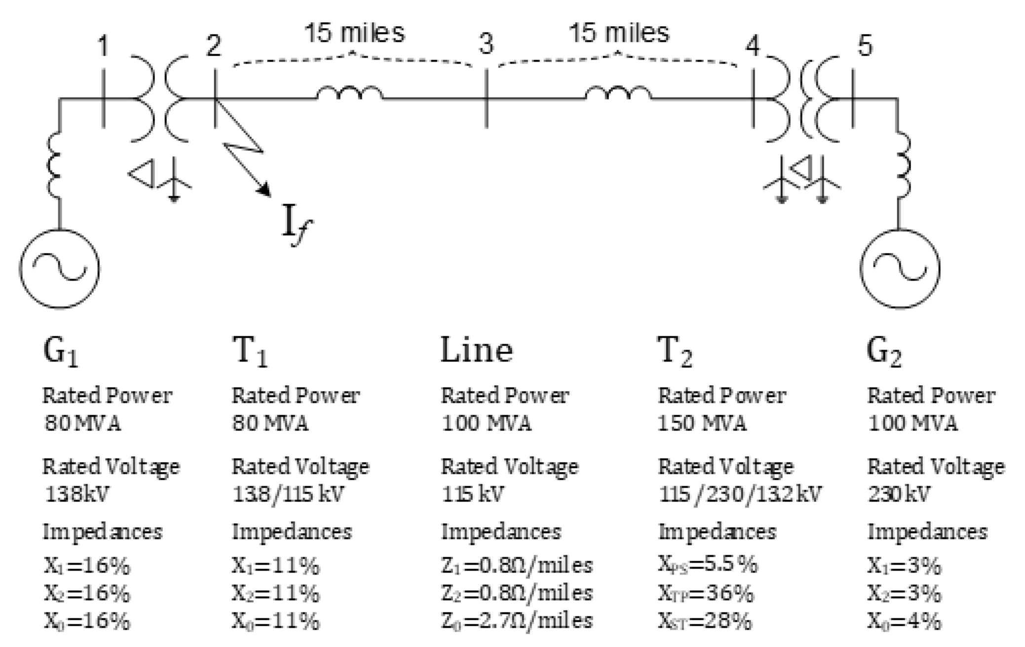
Figure 1. Simple power system with a DG. The numbers 1, 2, 3, 4, and 5 represent the bus indices.
Sustainability 14 09781 g001
Figure 2. Sequence network diagram of the test system with a synchronous machine-based distributed generation (SBDG). The numbers 1, 2, 3, 4, and 5 represent the bus indices.
Sustainability 14 09781 g002
Figure 3. Fault current contributions in the system with an SBDG: (a) ampere unit and (b) per unit (pu) configurations. The numbers 1, 2, 3, 4, and 5 represent the bus indices.
Sustainability 14 09781 g003
Figure 4. Test system with an IBDG: (a) single-line diagram and (b) sequence network diagram. The numbers 1, 2, 3, 4, and 5 represent the bus indices.
Sustainability 14 09781 g004
Figure 5. Sequence equivalent circuit for the voltage source. The numbers 1, 2, 3, 4, and 5 represent the bus indices.
Sustainability 14 09781 g005
Figure 6. Fault current contribution from the voltage source in the system with an IBDG. The numbers 1, 2, 3, 4, and 5 represent the bus indices.
Sustainability 14 09781 g006
Figure 7. Sequence equivalent circuit for the current source. The numbers 1, 2, 3, 4, and 5 represent the bus indices.
Sustainability 14 09781 g007
Figure 8. Fault current contribution of the current source in the system with an IBDG. The numbers 1, 2, 3, 4, and 5 represent the bus indices.
Sustainability 14 09781 g008
Figure 9. Total fault current contribution from both the voltage and current sources in the system with an IBDG: (a) ampere unit and (b) pu. The numbers 1, 2, 3, 4, and 5 represent the bus indices.
Sustainability 14 09781 g009
Figure 10. Sequence equivalent circuits of the system with a DG. The unit is pu. (a) SBDG and (b) IBDG. The numbers 1, 2, 3, 4, and 5 represent the bus indices.
Sustainability 14 09781 g010
Figure 11. Currents in the system in the ABC domain with a DG. The unit is pu. (a) SBDG and (b) IBDG.
Sustainability 14 09781 g011
Figure 12. Currents in the system in the ABC domain with a DG: (a) SBDG and (b) IBDG. The unit is ampere. The system with DGs in the ABC domain (amperes).
Sustainability 14 09781 g012aSustainability 14 09781 g012b
Table 1. Literature survey of short-circuit analysis.
Previous StudiesSummary
[19]Observed that the wind turbine controller may reduce the negative-sequence component of fault currents; injected negative-sequence currents
[20]Presented the method that changed the fault current phase angle to minimize the system fault current
[21]Quantified the fault current contributions due to IBDGs using steady-state and transient analyses
[22]Conducted fault analysis due to IBDGs under balanced conditions
[23]Considered IBDG’s voltage-dependent control modes for short-circuit analysis of radial and meshed networks
[24]Considered fault contributions from unbalanced IBDGs
[25]Improved computational speed for fault analysis with IBDGs
Table 2. Bank connection types of a two-winding transformer. The symbols H and L denote the high- and low-voltage sides, respectively. The symbol N indicates a neutral line. The numbers 1, 2, and 0 represent the positive-, negative-, and zero-sequence networks, respectively.
Transformer Bank
Connection
Positive/Negative
Sequence
Zero
Sequence
Sustainability 14 09781 i001 Sustainability 14 09781 i002 Sustainability 14 09781 i003
Sustainability 14 09781 i004Same as above Sustainability 14 09781 i005
Sustainability 14 09781 i006Same as above Sustainability 14 09781 i007
Sustainability 14 09781 i008Same as above Sustainability 14 09781 i009
Sustainability 14 09781 i010Same as above Sustainability 14 09781 i011
Sustainability 14 09781 i012Same as above Sustainability 14 09781 i013
Sustainability 14 09781 i014Same as above Sustainability 14 09781 i015
Sustainability 14 09781 i016Same as above Sustainability 14 09781 i017
Table 3. Bank connection types of a three-winding transformer.
Transformer Bank
Connection
Positive/Negative
Sequence
Zero
Sequence
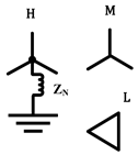
Sustainability 14 09781 i018 Sustainability 14 09781 i019 Sustainability 14 09781 i020
Sustainability 14 09781 i021Same as above Sustainability 14 09781 i022
Sustainability 14 09781 i023Same as above Sustainability 14 09781 i024
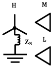
The symbols H, M, and L denote the high-, medium-, and low-voltage sides, respectively. These can also be expressed as P, S, and T, which indicate the primary, secondary, and tertiary sides. In general, the tertiary side is the lowest voltage side.
Table 4. Zero-sequence fault current behaviors according to the transformer topology.
Transformer TypeTopologyFault Current Behavior in the Zero-Sequence Network
Two-winding transformerD-Yg Sustainability 14 09781 i025
Yg-D Sustainability 14 09781 i026
Three-winding transformerY-D-Yg Sustainability 14 09781 i027
D-D-Yg Sustainability 14 09781 i028
Yg-D-Yg Sustainability 14 09781 i029
Table 5. Model parameters of the test system in per unit (pu).
SequenceImpedance of G1Impedance of T1Impedance of LineSecondary Impedance of T2Primary Impedance of T2Tertiary Impedance of T2Impedance of G2
Positive (symbol) j 0.2   ( X G 1 ( 1 ) ) j 0.1375   ( X T 1 ( 1 ) ) j 0.0907   ( X L ( 1 ) ) j 0.0083   ( X T 2 S ( 1 ) ) j 0.0450   ( X T 2 P ( 1 ) ) j 0.1950   ( X T 2 T ( 1 ) ) j 0.03   ( X G 2 ( 1 ) )
Negative (symbol) j 0.2   ( X G 1 ( 2 ) ) j 0.1375   ( X T 1 ( 2 ) ) j 0.0907   ( X L ( 2 ) ) j 0.0083   ( X T 2 S ( 2 ) ) j 0.0450   ( X T 2 P ( 2 ) ) j 0.1950   ( X T 2 T ( 2 ) ) j 0.03   ( X G 2 ( 2 ) )
Zero
(symbol)
j 0.2   ( X G 1 ( 0 ) ) j 0.1375   ( X T 1 ( 0 ) ) j 0.3062   ( X L ( 0 ) ) j 0.0083   ( X T 2 S ( 0 ) ) j 0.0450   ( X T 2 P ( 0 ) ) j 0.1950   ( X T 2 T ( 0 ) ) j 0.04   ( X G 2 ( 0 ) )
Table 6. Model parameters of the simulations in pu.
SequenceImpedance of G1Impedance of T1Impedance of LineSecondary Impedance of T2Primary Impedance of T2Tertiary Impedance of T2Norton Impedance of G2
Positive (symbol) j 0.2   ( X G 1 ( 1 ) ) j 0.1375   ( X T 1 ( 1 ) ) j 0.0907   ( X L ( 1 ) ) j 0.0083   ( X T 2 S ( 1 ) ) j 0.0450   ( X T 2 P ( 1 ) ) j 0.1950   ( X T 2 T ( 1 ) ) 10,000   ( Z G 2 ( 1 ) )
Negative (symbol) j 0.2   ( X G 1 ( 2 ) ) j 0.1375   ( X T 1 ( 2 ) ) j 0.0907   ( X L ( 2 ) ) j 0.0083   ( X T 2 S ( 2 ) ) j 0.0450   ( X T 2 P ( 2 ) ) j 0.1950   ( X T 2 T ( 2 ) ) 10,000   ( Z G 2 ( 2 ) )
Zero
(symbol)
j 0.2   ( X G 1 ( 0 ) ) j 0.1375   ( X T 1 ( 0 ) ) j 0.3062   ( X L ( 0 ) ) j 0.0083   ( X T 2 S ( 0 ) ) j 0.0450   ( X T 2 P ( 0 ) ) j 0.1950   ( X T 2 T ( 0 ) ) 10,000   ( Z G 2 ( 0 ) )
Table 7. Voltage values at each bus in the superposed circuit.
Bus No.VaVbVc3V0V0V1V2
Magnitude (Mag) (pu)Phase
Angle
(°)
Mag (pu)Phase
Angle
(°)
Mag (pu)Phase
Angle
(°)
Mag (pu)Phase
Angle
(°)
Mag (pu)Phase
Angle
(°)
Mag
(pu)
Phase
Angle
(°)
Mag (pu)Phase
Angle
(°)
10.7105−11.890.6201−92.031.0199131.310.000000.000000.75658.730.2664−101.35
20.000000.9438−55.750.9439153.050.4695−131.350.1565−131.350.606148.650.4496−131.35
30.123992.610.9890−48.010.9343155.030.2890−131.360.0963−131.360.640956.360.4496−131.35
40.247792.611.0504−41.060.9259157.050.1086−131.380.0362−131.380.686063.160.4496−131.36
50.279796.301.0783−39.860.9317159.390.1135−131.380.0378−131.380.706765.650.4496−131.36
Table 8. Current values through the lines in the superposed circuit.
FromToIaIbIc3I0I0I1I2
Bus No.Bus No.Mag (pu)Phase
Angle
(°)
Mag (pu)Phase
Angle
(°)
Mag (pu)Phase
Angle
(°)
Mag (pu)Phase
Angle
(°)
Mag (pu)Phase
Angle
(°)
Mag (pu)Phase
Angle
(°)
Mag (pu)Phase
Angle
(°)
123.6084−56.541.137597.350.8107−27.303.4142−41.311.1381−41.311.3860−84.441.3321−41.32
2 F3.9962−41.320.00000.000.00000.003.9962−41.321.3321−41.321.3321−41.321.3321−41.32
3 21.077920.181.1375−82.650.8107152.700.5820−41.350.1940−41.351.000030.000.000048.64
4 31.077920.181.1375−82.650.8107152.700.5820−41.350.1940−41.351.000030.000.000048.64
5 41.000130.001.0000−90.001.0000150.000.000048.620.000048.621.000030.000.000048.64
Table 9. Accuracy test results between MATLAB code and PSCAD/EMTDC. Note that the magnitude of 0.0000 represents a very small number.
MATLAB Code
(Frequency Domain)
PSCAD/EMTDC
(Time Domain)
V0V1V2V0V1V2
VoltageBusMag (pu)Phase Angle (°)Mag (pu)Phase Angle (°)Mag (pu)Phase Angle (°)Mag (pu)Phase Angle (°)Mag (pu)Phase Angle (°)Mag (pu)Phase Angle (°)
20.1565−131.350.606148.650.4496−131.350.1576−132.400.606748.410.4491−133.27
30.0963−131.360.640956.360.4496−131.350.0971−130.960.644356.000.4493−131.29
40.0362−131.380.686063.160.4496−131.350.0365−124.720.691262.670.4489−131.28
MATLAB code
(Frequency Domain)
PSCAD/EMTDC
(Time Domain)
I0I1I2I0I1I2
CurrentBusMag (pu)Phase angle (°)Mag (pu)Phase angle (°)Mag (pu)Phase angle (°)Mag (pu)Phase angle (°)Mag (pu)Phase angle (°)Mag (pu)Phase angle (°)
1→2(F)3.4142−41.311.3860−84.441.3321−41.323.4322−42.371.3841−84.361.3404−41.27
3→2(F)0.5820−41.351.000030.000.000048.640.5847−34.710.998030.110.0015−41.36
4→30.5820−41.351.000030.000.000048.640.5862−34.720.994230.500.0067−41.27
Table 10. Accuracy of the proposed short-circuit analysis.
Bus LocationFault Current Magnitude in MATLAB CodeBus LocationFault Current Magnitude in MATLAB Code
23.41423.43220.52
30.58200.58470.46
40.58200.58620.76
Table 11. Sequence networks of D-Yg, Yg-D, and Y-D-Yg/D-D-Yg.
Transformer Bank ConnectionSequence Network
Sustainability 14 09781 i030
D-Yg
Sustainability 14 09781 i031
Sustainability 14 09781 i032
Yg-D
Sustainability 14 09781 i033
Sustainability 14 09781 i034
Y-D-Yg
Sustainability 14 09781 i035
Sustainability 14 09781 i036
D-D-Yg
Sustainability 14 09781 i037
Table 12. Voltage values at each bus in the case of the D-Yg topology.
Bus No.VaVbVc3V0V0V1V2
Mag (pu)Phase
Angle
(°)
Mag (pu)Phase
Angle
(°)
Mag (pu)Phase
Angle
(°)
Mag (pu)Phase
Angle
(°)
Mag (pu)Phase
Angle
(°)
Mag (pu)Phase
Angle
(°)
Mag (pu)Phase
Angle
(°)
10.7161−11.091.0198131.311.0198131.310.000000.00000.000.76298.820.2598−101.35
20.000000.9525154.990.9525154.990.5358−131.350.1786−131.350.617048.650.4384−131.35
30.0907120.000.9646160.360.9646160.360.5358−131.350.1786−131.350.651756.230.4384−131.35
40.1815120.000.9850165.560.9850165.560.5358−131.350.1786−131.350.696662.940.4384−131.35
50.8455132.410.5058−170.160.505−170.160.00000.000.00000.000.7800101.450.4384−161.35
Table 13. Current values through the lines in the cases of the D-Yg topology.
FromToIaIbIc3I0I0I1I2
Bus No.Bus No.Mag (pu)Phase
Angle
(°)
Mag (pu)Phase
Angle
(°)
Mag (pu)Phase
Angle
(°)
Mag (pu)Phase
Angle
(°)
Mag (pu)Phase
Angle
(°)
Mag (pu)Phase
Angle
(°)
Mag (pu)Phase
Angle
(°)
121.6383−65.132.6358116.811.0000−60.000.00000.000.00000.001.3625−115.411.2990−11.35
2F3.8970−41.350.00000.000.00000.003.8970−41.351.2990−41.351.2990−41.351.2990−41.35
321.0001−150.001.000089.991.0000−30.000.00000.000.00000.001.0000−150.000.0000−131.35
431.0001−150.001.000089.991.0000−30.000.00000.000.00000.001.0000−150.000.0000−131.35
541.0001−150.001.000089.991.0000−30.000.00000.000.00000.001.0000−150.000.0000−131.35
Table 14. Voltage values at each bus in the case of the Yg-D topology.
Bus No.VaVbVc3V0V0V1V2
Mag (pu)Phase
Angle
(°)
Mag (pu)Phase
Angle
(°)
Mag (pu)Phase
Angle
(°)
Mag (pu)Phase
Angle
(°)
Mag (pu)Phase
Angle
(°)
Mag (pu)Phase
Angle
(°)
Mag (pu)Phase
Angle
(°)
10.7090−12.100.6177−91.851.0198131.310.00000.000.00000.000.75478.710.2681−101.35
20.00000.000.9415−55.230.9415152.530.4516−131.350.1505−131.350.603048.650.603048.65
30.135288.160.9863−46.620.9276153.610.2258−131.360.0753−131.360.637856.400.4525−131.35
40.270388.161.0512−38.920.9141154.730.0001138.660.0000138.660.683063.230.4525−131.35
50.8432134.051.1963−26.720.4871−171.950.00000.000.00000.000.7671101.850.4525−161.35
Table 15. Current values through the lines in the case of the Yg-D topology.
FromToIaIbIc3I0I0I1I2
Bus No.Bus No.Mag (pu)Phase
Angle
(°)
Mag (pu)Phase
Angle
(°)
Mag (pu)Phase
Angle
(°)
Mag (pu)Phase
Angle
(°)
Mag (pu)Phase
Angle
(°)
Mag (pu)Phase
Angle
(°)
Mag (pu)Phase
Angle
(°)
121.7045−64.152.7028117.381.0000−60.000.00000.000.00000.001.3927−114.221.3406−11.35
2F4.0218−41.350.00000.000.00000.004.0218−41.351.3406−41.351.3406−41.351.3406−41.35
321.1036−162.181.176999.020.7605−26.360.7374138.660.2458138.661.0000−150.000.0000−131.35
431.1036−162.181.176999.020.7605−26.360.7374138.660.2458138.661.0000−150.000.0000−131.35
541.0001−150.001.000089.991.0000−30.000.00000.000.00000.001.0000−150.000.0000−131.35
Table 16. Voltage values in pu at each bus in the case of the Y-D-Yg/D-D-Yg topologies.
Bus No.VaVbVc3V0V0V1V2
Mag (pu)Phase
Angle
(°)
Mag (pu)Phase
Angle
(°)
Mag (pu)Phase
Angle
(°)
Mag (pu)Phase
Angle
(°)
Mag (pu)Phase
Angle
(°)
Mag (pu)Phase
Angle
(°)
Mag (pu)Phase
Angle
(°)
10.7161−11.090.6289−92.691.0198131.310.00000.000.00000.000.76298.820.2598−101.35
20.00000.000.9525−57.690.9525154.990.5358−131.350.1786−131.350.617048.650.4384−131.35
30.0907120.001.0039−53.310.9646160.360.5358−131.350.1786−131.350.651756.230.4384−131.35
40.1815120.001.0607−49.370.9850165.560.5358−131.350.1786−131.350.696662.940.4384−131.35
50.323188.421.0792−38.440.9224157.840.00000.000.00000.000.717265.400.4384−131.35
Table 17. Current values in pu through lines in the cases of the Y-D-Yg/D-D-Yg topologies.
FromToIaIbIc3I0I0I1I2
Bus No.Bus No.Mag (pu)Phase
Angle
(°)
Mag (pu)Phase
Angle
(°)
Mag (pu)Phase
Angle
(°)
Mag (pu)Phase
Angle
(°)
Mag (pu)Phase
Angle
(°)
Mag (pu)Phase
Angle
(°)
Mag (pu)Phase
Angle
(°)
121.6383−65.132.6358116.811.0000−60.000.00000.000.00000.001.3625−115.411.2990−11.35
2F3.8970−41.350.00000.000.00000.003.8970−41.351.2990−41.351.2990−41.351.2990−41.35
321.0001−150.001.000090.001.0000−30.000.00000.000.00000.001.0000−150.000.0000−131.35
431.0001−150.001.000090.001.0000−30.000.00000.000.00000.001.0000−150.000.0000−131.35
541.0001−150.001.000090.001.0000−30.000.00000.000.00000.001.0000−150.000.0000−131.35
Publisher’s Note: MDPI stays neutral with regard to jurisdictional claims in published maps and institutional affiliations.