
Experimental Study on the Shear Mechanical Properties of Anchor Cable with C-Shaped Tube

Abstract
:1. Introduction
- (1)
- After the roadway is excavated, under the action of in situ stress, there is normal stress in the joint surface itself (hereinafter referred to as the initial normal stress for the convenience of differentiation). However, the influence of the initial normal stress has not been considered in the reported papers.
- (2)
- When using the double shear test method to study the influence of the angle between the bolt and the joint surface on the shear resistance, two bolts are used to penetrate the joint surface on both sides, respectively. On the one hand, this test method does not consider the reinforcement effect of the axial force of the bolt on the joint surface. On the other hand, the two bolts are independent of each other, and the force transmission is not continuous.
- (3)
- Most of the papers mainly focus on the tensile and shear properties of the anchor rod. Compared with the anchor rod, the anchor cable is composed of multiple steel strands, and its stress situation is more complex, more discrete, and more tensile than shear fracture phenomena.
- (4)
- Currently, the research on the tensile and shear properties of bolts and cables mainly focuses on the anchorage section of bolts and cables. However, in China’s coal mine roadway, many bolt and cable shears break in the free section. A tube cable composite structure—Anchor Cable with a C-shaped tube (hereinafter referred to as ACC) developed by Shan Renliang et al. [7]—could effectively optimize the shear resistance of free sections and restrain the occurrence of shear fractures, which make contributions to roadway stability and the sustainable development of the coal industry.
2. Shear Mechanical Behavior of Anchored Rock Mass
3. Test Preparation
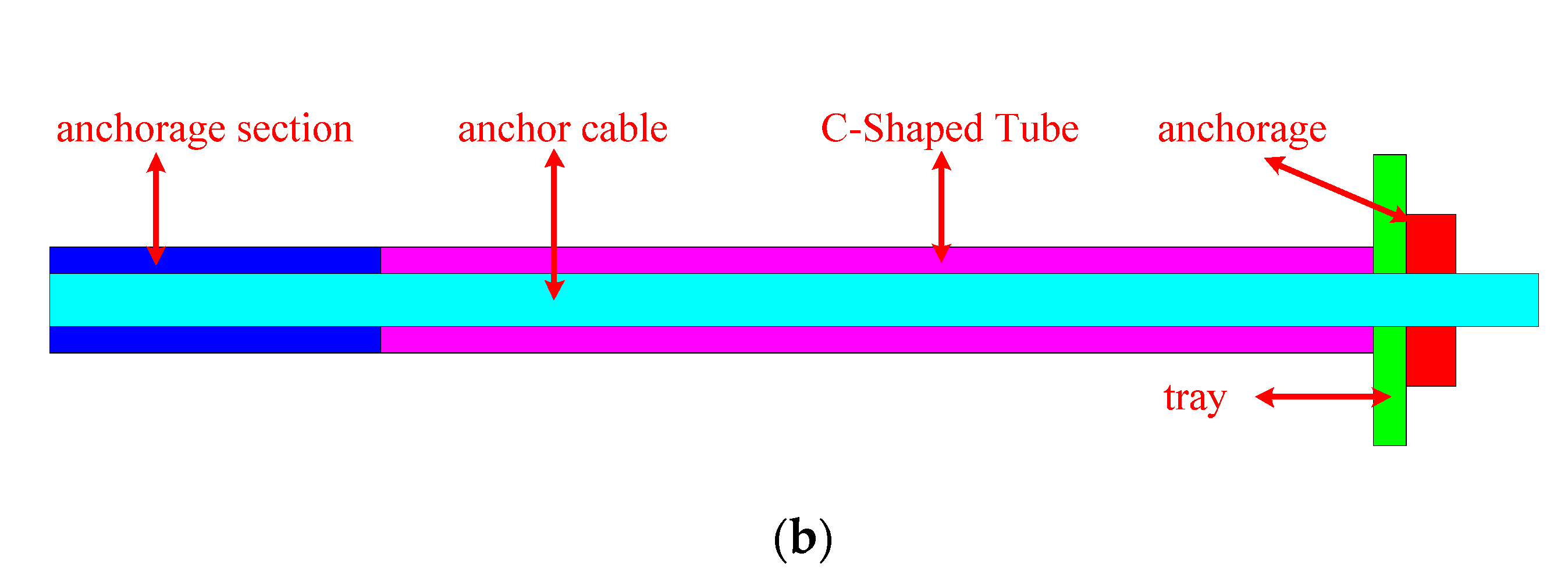
3.1. Brief Introduction of Tube Cable Composite Structurse
3.2. Test Equipment
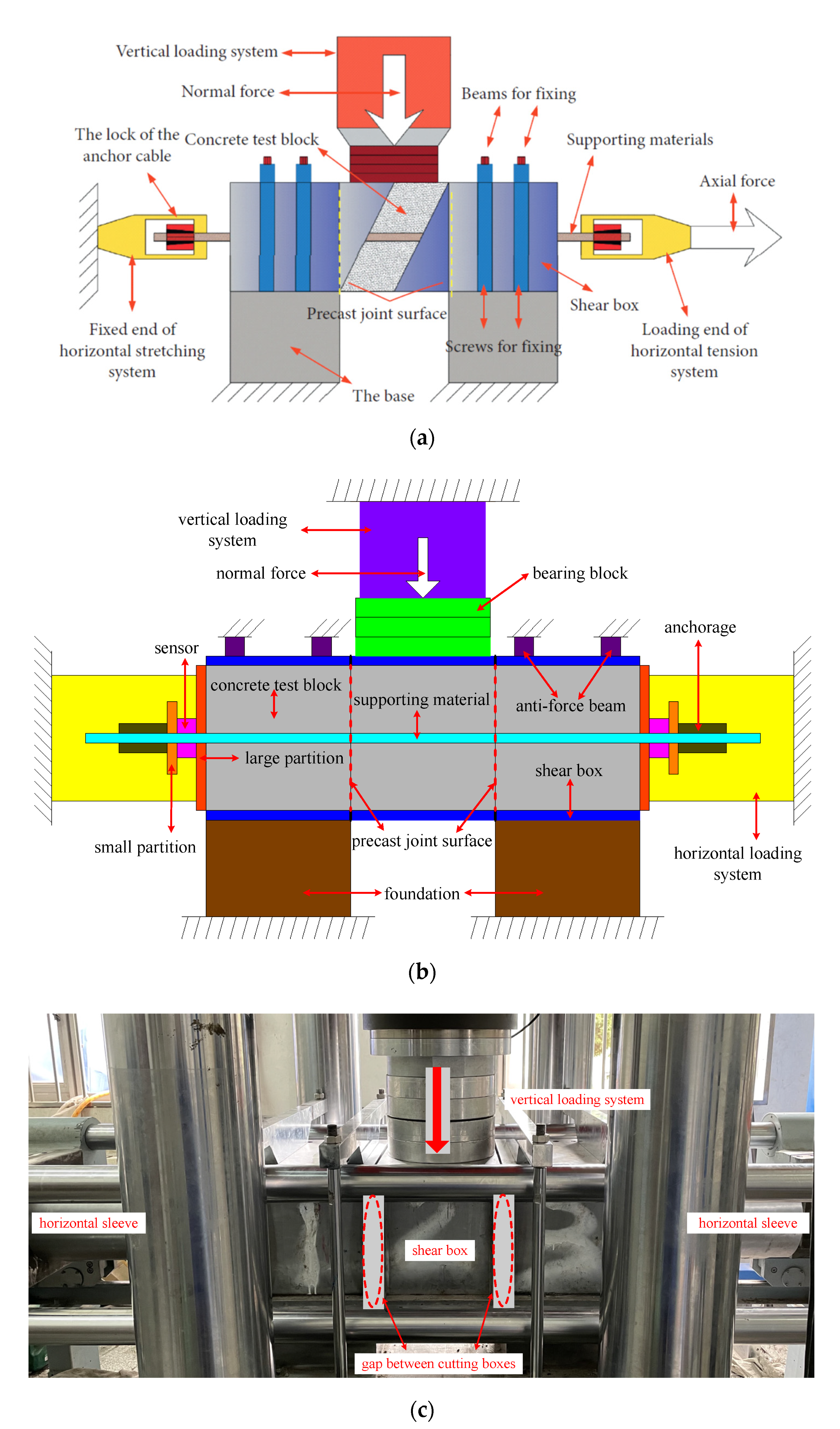
3.2.1. Cutting Box
- During the deformation of the anchor cable, a large axial force will be generated. The axial force is applied to the concrete block through the anchor and the large diaphragm so that the concrete block will deform along the length of the anchor cable, resulting in the size of the concrete block being slightly smaller than the size of the shear box, as shown in Figure 2a.
- During the installation process, it is difficult to ensure that the concrete block and the shear box are closely connected, and the joint surface being located inside the shear box could barely be avoided; that is, the joint surface is not coplanar with the shear line, as shown in Figure 2b.
3.2.2. Included Angle
3.2.3. Initial Normal Stress
3.3. Test Plan
3.4. Test Procedure
- (1)
- Mix the materials evenly according to the ratio of water:cement:stone:sand = 1:2:4:4, and make concrete blocks with a size of 300 mm × 300 mm × 300 mm in the mold. Place a steel tube with an outer diameter of 32 mm horizontally in the center of the mold in advance to form precast holes with a diameter of 32 mm. Meanwhile, make small blocks of 100 mm × 100 mm × 100 mm to characterize the uniaxial compressive strength of large blocks.
- (2)
- After formwork removal and curing for more than 28 days, a uniaxial compression test shall be conducted to test the strength of concrete blocks. The uniaxial compression rate is 2 mm/min. According to the test results, the uniaxial compressive strength of concrete blocks is determined to be 40 MPa.
- (3)
- Coat the inside of the shear box with grease to reduce the friction between the block and the shear box, then install each test device component and carry out the double shear test with a shear rate of 2 mm/min according to Table 1 of the test scheme.

| Test Number | Support Component | Angle ° | Initial Normal Stress MPa | Designed Preload kN | Actual Preload kN | Maximum of Shear Force kN | Average of Shear Stiffness kN/mm |
|---|---|---|---|---|---|---|---|
| NO1 | ϕ21.8 mm Anchor cable | 90 | 1.5 | 200 | 236.4 | 1159.5 | 8.6 |
| NO2 | ϕ21.8 mm ACC | 90 | 1.5 | 200 | 201.9 | 1719.8 | 12.3 |
| NO3 | ϕ21.8 mm Anchor cable | 80 | 1.5 | 200 | 184.2 | 1341.7 | 8.2 |
| NO4 | ϕ21.8 mm ACC | 80 | 1.5 | 200 | 195.7 | 1557.7 | 11.2 |
| NO5 | ϕ21.8 mm Anchor cable | 90 | 0 | 200 | 212.2 | 1352.8 | 10.0 |
| NO6 | ϕ21.8 mm ACC | 90 | 0 | 200 | 223.3 | 1406.3 | 10.0 |
| NO7 | ϕ21.8 mm Anchor cable | 90 | 3 | 200 | 216.1 | 1300.0 | 7.9 |
| NO8 | ϕ21.8 mm ACC | 90 | 3 | 200 | 201.8 | 1604.0 | 9.0 |
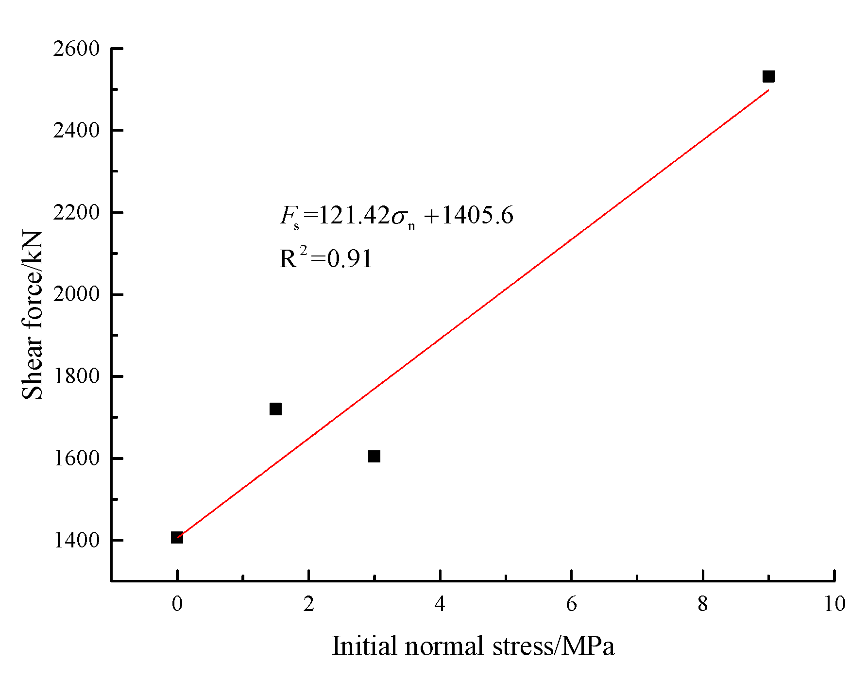
| NO9 | ϕ21.8 mm ACC | 90 | 9 | 200 | 219.5 | 2531.8 | 8.2 |
4. Analysis of Test Results
4.1. Failure Characteristics of Supporting Components
4.2. Failure Characteristics of the Joint Surface
4.3. Internal Friction Angle and Cohesion
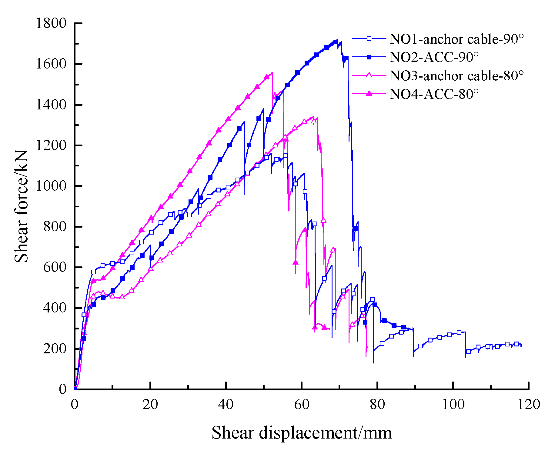
4.4. Shear-Bearing Capacity of the Joint Surface
- (1)
- During the shear process of the joint plane, while the anchor cable has its bearing capacity, the C-shaped tube, as a part of the tube cable’s composite structure, not only gives full play to its shear performance but also effectively reduces the occurrence of stress concentration near the joint plane and plays a protective role for the anchor cable.
- (2)
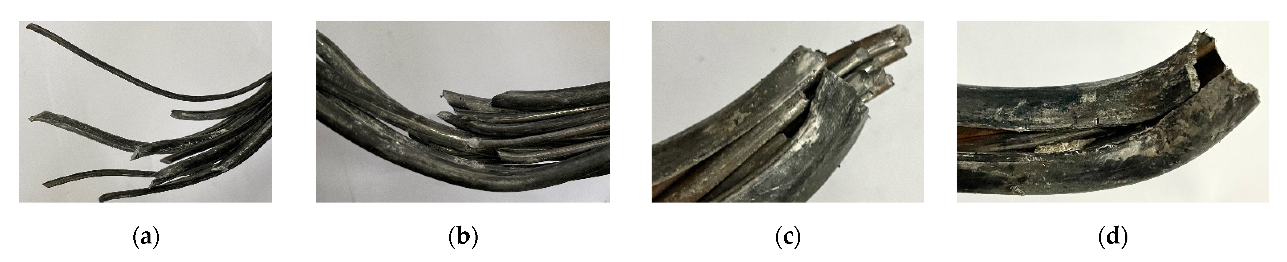
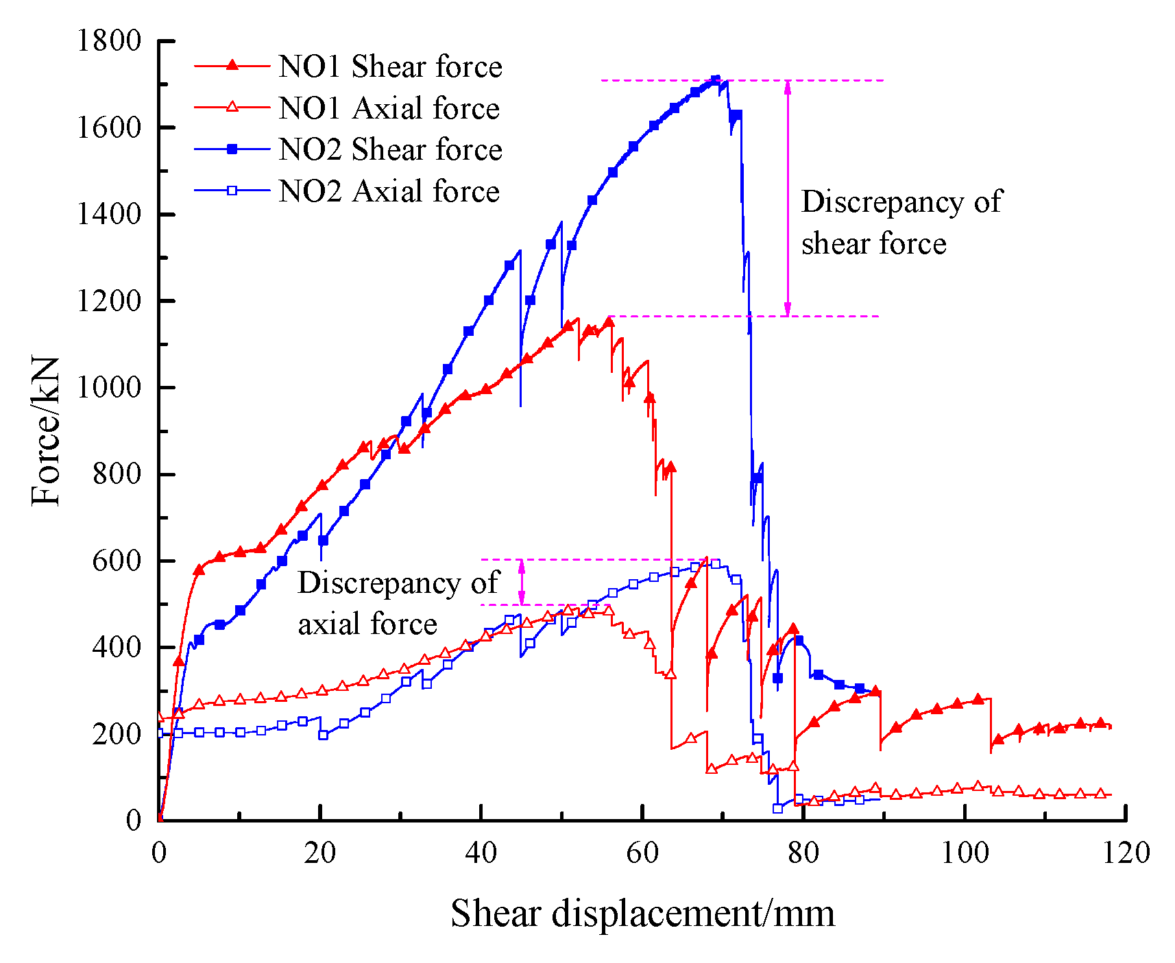
- After the C-shaped tube holds and wraps the anchor cable through the friction between the C-shaped tube and the anchor cable, the mechanical properties of the anchor cable in the original state are improved, making the anchor cable gradually transition from tensile shear failure to tensile failure. This is also proved by the shear displacement axial force curve, as shown in Figure 7. It is also consistent with the fracture failure characteristics of the anchor cable and ACC in Figure 4 in Section 3.1.
4.5. Shear Displacement
5. Discussion
5.1. Shear Stiffness
5.2. Increase in Shear Capacity
5.2.1. Interaction between Supporting Components and Joint Surface
5.2.2. Dowel Effect
6. Conclusions
- (1)
- The fracture failure mode of the anchor cable is mainly an oblique shear fracture, and the fracture failure mode of the anchor cable in ACC is mainly a conical fracture with a necking phenomenon under tension. The joint surfaces on both sides of the middle block have “+”-shaped cracks starting from the orifice, respectively, and the cracks on the joint surfaces of the blocks on both sides expand in the direction of gravity, respectively.
- (2)
- The C-shaped tube not only bears the load itself but also protects the anchor cable, effectively reduces the occurrence of stress concentration near the joint surface, improves the stress state of the anchor cable through the friction between the C-shaped tube and the anchor cable, maximizes the tensile performance of the anchor cable and makes the failure mode of the anchor cable transition from tensile shear failure to tensile failure.
- (3)
- Compared with the anchor cable, ACC has a higher shear capacity, greater shear stiffness and higher ductility in the shear direction. When ACC is perpendicular to the joint plane, the shear capacity of the joint surface is higher than when it is inclined and linear with the initial normal stress.
- (4)
- Two methods are proposed to evaluate the increased range of the ACC shear capacity. One is the joint plane shear capacity method considering the interaction between the support member and the joint plane. The other is the support member bearing capacity method considering only the “dowel effect” of the support member. Compared with the anchor cable, the average increase in the shear capacity of the joint surface of ACC is 306 kN, which is greater than the average increase in the shear capacity of the supporting components by 279 kN. However, the average increase in the shear capacity of the joint surface is only 25.2%, which is less than the average increase in the shear capacity of the supporting components by 34.9%. When comparing the shear-bearing capacity of the anchor cable and ACC, it is suggested that the shear-bearing capacity of support components should be used to evaluate the ability of support components to resist shear deformation. The shear-bearing capacity of the joint surface should be used to evaluate the control effect of support components on the joint surface’s shear deformation.
Author Contributions
Funding
Institutional Review Board Statement
Informed Consent Statement
Data Availability Statement
Acknowledgments
Conflicts of Interest
References
- Qin, D.; Wang, X.; Zhang, D.; Chen, X. Study on surrounding rock-bearing structure and associated control mechanism of deep soft rock roadway under dynamic pressure. Sustainability 2019, 11, 1892. [Google Scholar] [CrossRef] [Green Version]
- Wu, C.; Qin, T.; Wang, L.; Liu, Z. Research on surrounding rock control technology of dongbaowei deep mining roadway. Adv. Civ. Eng. 2021, 2021, 6660989. [Google Scholar] [CrossRef]
- Zhao, X.; Li, H.; Zhang, S.; Yang, X. Stability analyses and cable bolt support design for A deep large-span stope at the hongtoushan mine, China. Sustainability 2019, 11, 6134. [Google Scholar] [CrossRef] [Green Version]
- Li, C.C. Field observations of rock bolts in high stress rock masses. Rock Mech. Rock Eng. 2010, 43, 491–496. [Google Scholar] [CrossRef]
- Li, L.; Hagan, P.C.; Saydam, S.; Hebblewhite, B.; Li, Y. Parametric study of rockbolt shear behaviour by double shear test. Rock Mech. Rock Eng. 2016, 49, 4787–4797. [Google Scholar] [CrossRef]
- Yang, R.; Li, Y.; Wang, M.; Zhu, Y.; Cheng, Y.X.; Xiao, C.L.; Zhao, Y. Experimental study of shear mechanical properties of prestressed cable bolts. J. China Univ. Min. Technol. 2018, 47, 1166–1174. [Google Scholar]
- Shan, R.; Tao, Y.; Kong, X.; Huang, B. Anchor Cable with C-Shaped Tube—Supporting Structure Capable of Bearing Transverse Shear Force, China. CN201410206614.5, 2 March 2016. [Google Scholar]
- Shan, R.; Zhang, S.; Huang, P.; Liu, W. Research on full-section anchor cable and C-shaped tube support system of deep layer roadway. Geofluids 2021, 2021, 5593601. [Google Scholar] [CrossRef]
- Shan, R.; Huang, P.; Yuan, H.; Meng, C.; Zhang, S. Research on the full-section anchor cable and C-shaped tube support system of mining roadway in island coal faces. J. Asian Archit. Build. Eng. 2022, 21, 298–310. [Google Scholar] [CrossRef]
- Grasselli, G. 3D behaviour of bolted rock joints: Experimental and numerical study. Int. J. Rock Mech. Min. Sci. 2005, 42, 13–24. [Google Scholar] [CrossRef]
- Li, X.; Aziz, N.; Mirzaghorbanali, A.; Nemcik, J. Behavior of Fiber Glass Bolts, Rock Bolts and Cable Bolts in Shear. Rock Mech. Rock Eng. 2016, 49, 2723–2735. [Google Scholar] [CrossRef]
- Aziz, N.; Hawker, R.; Mirzaghorbanali, A.; Nemick, J.; Li, X.; Rasekh, H. Strength characteristics of secura hollow groutable cable bolts. In Proceedings of the Coal Operators’ Conference, Wollongong, Australia, 16–18 September 2015. [Google Scholar]
- Mirzaghorbanali, A.; Rasekh, H.; Aziz, N.; Yang, G.; Khaleghparast, S.; Nemcik, J. Shear strength properties of cable bolts using a new double shear instrument, experimental study, and numerical simulation. Tunn. Undergr. Space Technol. 2017, 70, 240–253. [Google Scholar] [CrossRef]
- Maiolino, S.R.; Pellet, F.L. Full scale lab testing for the determination of rock bolt contribution to reinforced joint shear strength. In Proceedings of the ISRM International Congress of Rock Mechanics, Salzburg, Austria, 9–14 October 2015. [Google Scholar]
- Li, L.; Hagan, P.C.; Saydam, S.; Hebblewhite, B.; Zhang, C. A laboratory study of shear behaviour of rockbolts under dynamic loading based on the drop test using a double shear system. Rock Mech. Rock Eng. 2019, 52, 3413–3429. [Google Scholar] [CrossRef]
- Pellet, F.L.; Egger, P.H. Analytical model for the mechanical behaviour of bolted rock joints subjected to shearing. Rock Mech. Rock Eng. 1996, 29, 73–97. [Google Scholar] [CrossRef]
- Li, C. Experimental study on shear mechanical properties of high strength threaded steel bolt. Eng. Mech. 2021, 38, 151–158. [Google Scholar]
- Yang, G. Study on the Behaviors and Failure Characteristics of Cable Bolt under Various Shearing Loading Experimental Environment. Ph.D. Thesis, China University of Mining & Technology, Xuzhou, China, 2017. [Google Scholar]
- Ma, W.; Li, Y.; Ding, K.; Cheng, B.; Liu, J.; Hao, J.; Tam, V.W.Y. Mechanical properties of new dry-type beam-column bolt connection Joint. Sustainability 2019, 11, 3348. [Google Scholar] [CrossRef] [Green Version]
- Li, X.; Yang, G.; Nemcik, J.; Mirzaghorbanali, A.; Aziz, N. Numerical investigation of the shear behaviour of a cable bolt in single shear test. Tunn. Undergr. Space Technol. 2019, 84, 227–236. [Google Scholar] [CrossRef]
- Shan, R.; Bao, Y.; Huang, P.; Liu, W.; Li, G. Study on Double-Shear Test of Anchor Cable and C-Shaped Tube. Shock. Vib. 2021, 2021, 9948424. [Google Scholar] [CrossRef]
- Chen, Y. Experimental study and stress analysis of rock bolt anchorage performance. J. Rock Mech. Geotech. Eng. 2014, 6, 428–437. [Google Scholar] [CrossRef]
- Cai, M. Rock Mechanics and Engineering, 2nd ed.; Science Press: Beijing China, 2013. [Google Scholar]
- Li, L.; Hagan, P.C.; Saydam, S.; Hebblewhite, B. Shear resistance contribution of support systems in double shear test. Tunn. Undergr. Space Technol. 2016, 56, 168–175. [Google Scholar] [CrossRef]
- Shan, R.; Tong, X.; Huang, P.; Yuan, H.H.; Bao, Y.S.; Liu, N. Research on the anchor cable combined with the c-shaped tube and the mechanical properties. Rock Soil Mech. 2022, 43, 602–614. [Google Scholar]


| Test Number | Support Component | Test Group | SBC-JS kN | Increase in SBC-JS kN | Percentage of the Increase in SBC-JS % | SBC-SC kN | Increase in SBC-SC kN | Percentage of the Increase in SBC-SC % |
|---|---|---|---|---|---|---|---|---|
| NO1 | ϕ21.8 mm Anchor cable | A | 1159.5 | 560.3 | 48.3 | 745.6 | 501.0 | 67.2 |
| NO2 | ϕ21.8 mmACC | 1719.8 | 1246.5 | |||||
| NO3 | ϕ21.8 mm Anchor cable | B | 1341.7 | 216.1 | 16.1 | 949.4 | 191.2 | 20.1 |
| NO4 | ϕ21.8 mm ACC | 1557.7 | 1140.6 | |||||
| NO5 | ϕ21.8 mm Anchor cable | C | 1352.8 | 53.5 | 4.0 | 955.4 | 122.5 | 12.8 |
| NO6 | ϕ21.8 mm ACC | 1406.3 | 1077.9 | |||||
| NO7 | ϕ21.8 mm Anchor cable | D | 1299.9 | 304.1 | 23.4 | 866.0 | 213.3 | 24.6 |
| NO8 | ϕ21.8 mm ACC | 1604.0 | 1079.4 |
Publisher’s Note: MDPI stays neutral with regard to jurisdictional claims in published maps and institutional affiliations. |
© 2022 by the authors. Licensee MDPI, Basel, Switzerland. This article is an open access article distributed under the terms and conditions of the Creative Commons Attribution (CC BY) license (https://creativecommons.org/licenses/by/4.0/).
Share and Cite
Shan, R.; Liu, W.; Li, G.; Liang, C.; Shi, S.; Chen, Y.; Zhang, S. Experimental Study on the Shear Mechanical Properties of Anchor Cable with C-Shaped Tube. Sustainability 2022, 14, 9616. https://doi.org/10.3390/su14159616
Shan R, Liu W, Li G, Liang C, Shi S, Chen Y, Zhang S. Experimental Study on the Shear Mechanical Properties of Anchor Cable with C-Shaped Tube. Sustainability. 2022; 14(15):9616. https://doi.org/10.3390/su14159616
Chicago/Turabian StyleShan, Renliang, Weijun Liu, Gengzhao Li, Chen Liang, Shuguo Shi, Ye Chen, and Shupeng Zhang. 2022. "Experimental Study on the Shear Mechanical Properties of Anchor Cable with C-Shaped Tube" Sustainability 14, no. 15: 9616. https://doi.org/10.3390/su14159616
APA StyleShan, R., Liu, W., Li, G., Liang, C., Shi, S., Chen, Y., & Zhang, S. (2022). Experimental Study on the Shear Mechanical Properties of Anchor Cable with C-Shaped Tube. Sustainability, 14(15), 9616. https://doi.org/10.3390/su14159616