Article

Environmental Impact Analysis of Oil and Gas Pipe Repair Techniques Using Life Cycle Assessment (LCA)

1
Mechanical Engineering Department, King Fahd University of Petroleum and Minerals, Dhahran 31261, Saudi Arabia
2
Interdisciplinary Research Center for Advanced Materials, King Fahd University of Petroleum and Minerals, Dhahran 31261, Saudi Arabia
3
Architectural Engineering Department, King Fahd University of Petroleum and Minerals, Dhahran 31261, Saudi Arabia
4
Department of Mechanical Engineering, Texas A&M University Texarkana, 7101 University Avenue, Texarkana, TX 75503, USA
*
Author to whom correspondence should be addressed.
Sustainability 2022, 14(15), 9499; https://doi.org/10.3390/su14159499
Submission received: 31 May 2022 / Revised: 3 July 2022 / Accepted: 12 July 2022 / Published: 2 August 2022
(This article belongs to the Special Issue Buildings and Sustainable Energy: Technologies, Policies, and Trends)

Abstract

:
External corrosion is one of the major defects for oil and gas pipes. Multiple repair techniques are used for repairing such pipes, which have different environmental effects. In this study, the life cycle assessment (LCA) approach has been used to investigate the environmental impacts of four commonly used repair techniques. The techniques are fillet welded patch (FWP), weld buildup (WB), mechanical clamp (MC), and non-metallic composite overwrap (NCO). The repair processes based on guidelines from repair standards are carried out on a defected pipe specimen and experimental data required for LCA are collected. The paper conducts a cradle-to-gate LCA study using SimaPro software. Six environmental impact categories are used for the comparison of repair processes. The results for a repair life of ten years indicate that non-metallic composite overwrap has the highest whereas the fillet welded patch has the lowest environmental impacts.

1. Introduction

The oil and gas industry is one of the largest industrial sectors, and all stages of exploration, processing and distribution pose environmental challenges. A pipe is the most economical and efficient channel to transport oil and gas. Globally, the pipelines used for gas and crude oil products span over 1.7 million km in length [1]. Over time, pipes tend to deteriorate due to various factors including corrosion that leads to pipe failures [2]. Apart from corrosion, pipelines can fail due to material failure, weld failure, or accidental damage during excavation. The estimated loss due to corrosion in such pipelines is between 2 and 3.3 billion USD only in the United States [1]. Local external corrosion may occur over small regions because of several factors such as accidental removal of the surface coating. The decision about repair or replacement of such defective pipes depends on the nature and the severity of the defect [3]. The factors such as remaining pipe thickness, operational parameters, and cost are the governing parameters for a decision. It is always preferred to repair a corroded pipe rather than replace it due to cost considerations [4]. Several methods are available to repair a damaged pipe [5]. Common repair methods are fillet welded patch, flush welded patch, weld buildup, mechanical clamp, non-metallic composite repair system, and non- metallic lining of the pipe. These repair methods fall into three broad categories. The first category relies on welding to deposit extra material in the corroded section of the pipe. In this way, the extra material provides strength to the pipe section. Welding, however, requires the pipeline to be isolated, and disruption in the transportation of oil and gas can happen. The second method overcomes this limitation by reinforcing the pipeline by using a metallic sleeve or a collar around the corroded section. This metallic sleeve and collar provides the strength to the corroded section. Metallic sleeves are usually bolted on the pipe and therefore they do not disrupt the transportation. The last method relies on using a composite material to reinforce the corroded section. Multiple layers of composite material are wrapped around the corroded section. Usually, the selection of a method depends on the size and nature of the defect [5].
Oil and gas are flammable substances and they are usually delivered under pressure via pipelines. Failure of oil and gas pipelines has several environmental risks. A failed pipeline can lead to fire, explosions, and the release of toxic substances into the environment [6]. Similarly, materials and energy consumed during the operation and maintenance of these pipelines can pose several environmental issues including greenhouse gas emissions and the release of hazardous wastes into air, water, and land. It is, therefore, important to understand the environmental performance of various activities related to the maintenance of these pipelines.
The environmental performance of repair techniques relies on the repair procedures. Life cycle assessment (LCA), an ISO standardized tool, is one of the most important environmental impact assessment approaches being used across the world in wide ranging sectors [7,8]. Apart from LCA, other techniques such as checklists, streamline LCA, and network diagrams can also be used. However, LCA is the most commonly used tool for technology comparison from the sustainability perspective [9,10] It evaluates the environmental performance of a process or activity by collecting information during its entire life [9]. LCA helps identify the contribution of materials, energy, and transportation for the processes under study. LCA is a globally recognized method [10]. LCA can assess a variety of environmental impacts over the life cycle of a product. The LCA procedure comprises four stages [8,9] which are typically done iteratively to account for modifications. These four stages include: goal and scope definition, life cycle inventory analysis (LCI), life cycle impact assessment (LCIA), and interpretation. Several researchers have used LCA to analyze potential environmental impacts of various products and systems [11,12,13].
The objective of the current study is to evaluate and compare the environmental effects of the most frequently used pipe repair techniques in the oil and gas sector of the Middle East. The oil and gas sector is the largest economic sector in the Middle East, and currently, there are more than 30,000 km of oil and gas pipelines in the Middle East [14]. Results of the study are expected to help industry practitioners to understand the important environmental issues related to pipe repair and to improve processes to reduce the associated environmental impacts. Several studies have been conducted using LCA to measure the environmental impacts. Studies related to current research are summarized next.

2. Literature Review

Life cycle assessment (LCA) is a widely used technique to study the environmental impacts of various products and processes. These studies indicated various hot spots during the life cycle of a product that contribute most towards the environmental degradation. Products including wind turbines [11] and polymer composites [12] have been studied using LCA. LCA of electronics boards used in different products has also been carried out [13]. However, a study on the environmental impacts of oil and gas pipe repair techniques is not reported yet. Nevertheless, several studies exist that address the environmental impacts of welding and composite materials, and their application in repair and manufacturing processes. A summary of these studies is provided next.
Researchers have studied the environmental impact of various welding processes. Sproesser et al. [15] compared manual arc welding, laser arc-hybrid welding, and two variants of gas metal arc welding using LCA. Based on a weld of 20 mm thick steel plate, they concluded that arc laser hybrid welding is considered the most environment-friendly welding procedure. Drakopoulos et al. [16] studied environmental impact of cutting and joining processes used for repairing ship hulls. These processes included oxy-acetylene cutting, plasma arc cutting, shielded metal arc welding, flux core arc welding and submerged arc welding. LCA results, based on two meters of cutting and welding as a functional unit, showed that flux core arc welding is 70% more hazardous as compared to shielded metal arc welding. The plasma arc cutting is reported to have negligible environmental impact as compared to oxy-acetylene cutting. Detailed assessment of welding processes, energy consumption and welding fumes estimation is studied in [17]. Laser welding with improved efficiency is studied in [18]. Welding fume generation rate for a variety of processes has also been calculated in [19]. In addition to welding processes, the environmental impact of welding waste materials such as electrode stubs is also reported in the literature [20,21]. Vimal et al. [20] proposed an environment-friendly disposal method for leftover electrode stubs.
Favi et al. [22] in their study developed a model that provides a common structure for life cycle assessment (LCA) and life cycle cost analysis (LCCA). They analyzed different design configurations for maritime vessels using the proposed model. Sproesser et al. [23] compared life cycle assessment of a 30-mm-thick weld done by single-wire gas metal arc welding (SGMAW) and high power tandem GMAW (TGMAW). Their study revealed that environmental impacts can be reduced by up to 11% using an energy-efficient TGMAW process. Chang et al. [24] applied LCA to state-of-art welding technologies, such as Manual Metal Arc Welding (MMAW), Manual Gas Metal Arc Welding (GMAW), Automatic GMAW and Automatic Laser-Arc Hybrid Welding (LAHW) to evaluate their environmental impacts. The LCA results indicate that for a 1-m weld seam, MMAW consumes the largest amount of resources (such as filler material and coating on electrodes) and energy, which contributes to comparatively higher environmental impacts. Sangwan et al. [25] evaluated the environmental impact generated due to welding for different materials. It was found in their study that in the production of machine/equipment (manufacturing phase), copper and mild steel are major polluters.
The use of non-metallic composite overwrap (NCO) in the oil and gas pipe industry has grown in recent years, and the composite material used in this technique comprises fiber and resin. Schmidt and Beyer [26] conducted LCA of two components made of polymers with different composite reinforcements. One polymer was reinforced with glass fiber and the other with hemp fiber. The study concluded that the glass fiber had more CO2, SO2, phosphate, and nitrate emissions than the hemp fiber. Corbière-Nicollier et al. [27] conducted an environmental impact analysis of transport pallets made of glass fiber and China reed fiber. The study suggested that China reed fiber had lower environmental impact as compared to glass fiber except for nitrate emissions in water.
Fiber-reinforced polymer composites are being used to strengthen and repair concrete structures. The aim is to avoid demolishing existing structures. The results of LCA studies have demonstrated that the approach is also an environment-friendly solution. Katz [28] found that the fiber-reinforced pavements were more environment-friendly as compared to steel-reinforced pavements due to less maintenance requirements. Maxineasa et al. [29] compared the environmental impact of a simple reinforced concrete beam with beams strengthened by fiber-reinforced polymers. They found that fiber-reinforced concrete beams contributed less towards the environmental degradation.
Ahmed I.M and Tsavdaridis K.D. [30] studied and compared environmental and economic impacts of three types of flooring systems in construction industry. Their proposed system based on fiber-reinforced polymer not only reduced the cost of the flooring system, but it was the least damaging to the environment. Vidal et al. [31] conducted a comprehensive life cycle assessment study of panels for aircraft interiors, including both a conventional glass fiber-reinforced panel and different novel sustainable panels. The study showed that all the sustainable panels had better environmental performance than the conventional panel. Among different sustainable panels, geopolymer had the best environmental performance. Nguyen et al. [32] studied and compared environmental and economic impacts of different types of polymeric materials in drainage pipe. Their study suggested that a nanocomposite design that replaces part of the pristine HDPE with recycled HDPE and nanoclay reduces environmental risks and material cost of corrugated pipe.
Abu Dabous et al. [33] discussed the life cycle analysis of bridge rehabilitation. Their study concluded that the deck replacement yields higher environmental impact and life cycle cost compared to repairing and strengthening the deck. Bizjak et al. [34] compared the environmental impacts of two different types of track renewal methods for railway transition zones using LCA. The study showed that track renewal by geo-composite and anchors had less environmental impact than track renewal by cement. Liu et al. [35] examined the environmental impacts of cast iron cylinder head block remanufacturing through laser cladding using life cycle assessment (LCA) and compared it with the new cylinder head block manufacturing. Their study revealed that cylinder head remanufactured by laser cladding can cut environmental impacts over the entire life cycle by 63.8% on average.
The literature review shows that LCA studies have been conducted for the use of welding and composite materials for repair. However, we could not find any studies addressing repair processes for the oil and gas industry, as well as any direct studies that focus on the comparison between welding and composite materials repair techniques. It is expected that the present work would contribute to filling this gap in this area.

3. Environmental Impact of Pipe Repair Techniques
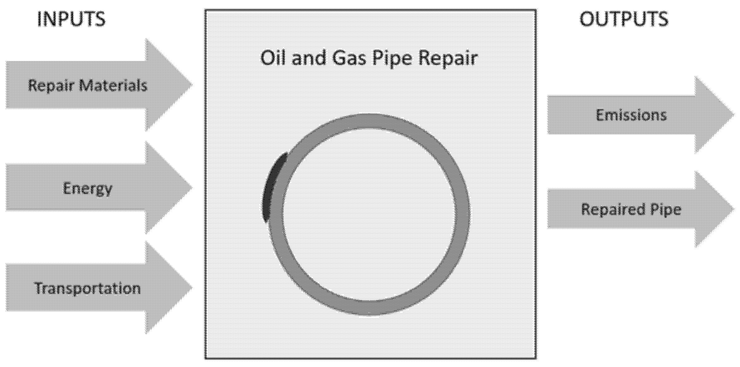
3.1. Methodology

The repair processes are experimentally performed in the lab conditions. Experimental inventory data are used for life cycle analysis of repair methods using the software SimaPro (Amersfoort, The Netherlands) and Ecoinvent database [36]. The cradle-to-gate approach has been followed to determine the environmental impacts of the repair processes. The pipe samples, defect sizes, and repair techniques were all conducted according to standard procedures used in the field. So the data collected in lab and the field are very identical in nature.

3.2. Oil and Gas Pipe Repair

In order to ensure data quality and repeatability, actual repair processes are performed experimentally on four sample pipes in the lab. NCO repair materials and mechanical clamps were imported from the United States and Turkey, respectively. Inventory data are established by the characterization of materials used in these processes. In welding repair techniques, filler material and gas consumption are measured. Electricity usage for welding procedures is decided with measured values and using plug efficiency of 80%.

3.2.1. Selection of Defect Size

Four oil and gas pipe samples of 168.3 mm diameter were obtained for the study. A defect as shown in Figure 1 is produced by machining the outer surface of the pipe. The defect size (Table 1) is selected to simulate an original corrosion defect in the field, and the ASME standard [5] provided the guidelines for repairing the local wall thinning defect. The standard recommends several repair techniques as a function of defect size. For our defect size, all four repair techniques under consideration can be used.

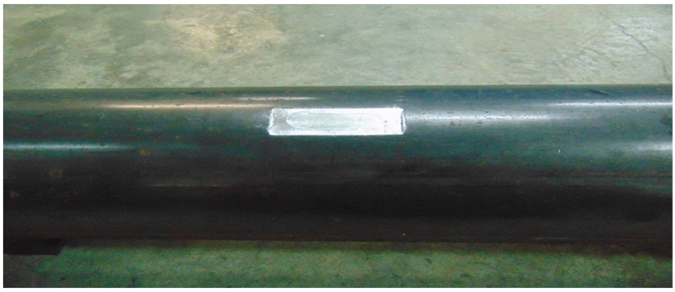
3.2.2. Fillet Welded Patch Repair (FWP)

For the FWP repair technique, the dimensions of the steel plate are calculated according to the standard [5]. A carbon steel plate of 98 mm in length and 3 mm thickness was welded on the defected portion of the pipe as shown in Figure 2a. Gas tungsten arc welding is used to attach the plate to the pipe. Pipes are cleaned with acetone prior to welding to remove dust, sand, and oily particles. Carbon steel rod and argon gas are used as filler material and shielding gas, respectively. Filler material and shielding gas consumption are measured during the welding process. Electricity consumption is determined by the measured values of current and voltage during the welding process. The measured inventory data are reported in Table 2.

3.2.3. Weld Buildup Repair (WB)

WB was performed by depositing the weld metal on the defected portion of pipe as shown in Figure 2b. The welding technique, filler material, and shielding gas are the same as for FWP. The metal deposition was extended beyond the defected length according to ASME PCC-2 [5]. The length of weld deposit in each direction beyond the affected portion of base metal was calculated by the following equation.
B = 3 4   R t n o m
where R = outer radius of the component, or 1 2 D and t n o m = nominal wall thickness of the component.
WB required multiple weld passes and thus consumed more welding resources than FWP. The measured inventory data are reported in Table 2.

3.2.4. Mechanical Clamp (MC)

MC was manufactured in Turkey for the given defect size and was air freighted to Saudi Arabia. The repaired pipe using MC is shown in Figure 2c. Inventory data were collected by characterizing the material used in the clamp. The corresponding inventory data are reported in Table 2.

3.2.5. Non-Metallic Composite Overwrap Repair (NCO)

The NCO repair kit was manufactured in the USA, and repair was performed per the guidelines provided by the manufacturer. The dimensions of composite overwrap are calculated according to ISO 14,224 [36] as follows.
For the slot type defect:
l over = 2 D t
where lover = extended length of composite beyond the defect length in one direction, D = outer diameter of pipe (mm), and t = thickness of pipe (mm).
The total axial length of the composite will be
l total = 2 l over + l defect + l avaliable ( mm )
Note: According to ISO TS 24817, l available i.e., available length is fixed to about 25 mm.
First the pipe surface was cleaned with acetone to remove dust particles and then the epoxy resin was applied. Finally, eight layers of glass fiber cloth were wrapped over the defected pipe. The final repaired pipe is shown in Figure 2d. The measured inventory data are reported in Table 2.

3.3. Life Cycle Assessment (LCA)

LCA is one of the most efficient and widely used methodologies to evaluate and examine the environmental impacts of a product, activity, or a process. ISO standard delineates four phases of LCA: goal and scope definition, life cycle inventory analysis, life cycle impact assessment, and interpretation [7,8].
SimaPro [37] software is used to conduct the LCA study of the pipe repair methods. The environmental impact assessment is made by using CML (a tool developed by a group of researchers under the supervision of the Center of Environmental Science of Leiden University). CML uses a midpoint approach methodology to analyze the environmental impacts [38].
Oil and gas repair processes vary in their respective service life. In the life cycle inventory phase, data of inputs for the selected repair procedures are composed according to functional unit and system boundaries. Figure 3 shows the system boundary used for this LCA study. The FWP, WB, and NCO have an average life of 10 years while the MC’s average life is 5 years. Therefore, 10 years life of the repair process is considered the functional unit.
Depending upon the purpose of a study, LCA can be applied to the whole life cycle of a process or a relevant section of a process. The cradle-to-gate approach is adopted for the current study. The approach includes material acquisition and the manufacturing stage only. Therefore, the transportation corresponding to the manufacturing stage, i.e., material transported to the manufacturing place is also considered. System boundaries of repair processes consider only consumption of material, electricity, and transportation, without considering machinery. The study is conducted assuming that repair will be performed in Saudi Arabia. Therefore, all the transportation values are calculated using Saudi Arabia as the final destination, and Saudi Arabian electricity mix is used to calculate environmental impacts of processes that required electricity (FWP and WB).
The most important environmental impact categories in the oil and gas sector are global warming potential (GWP), acidification potential (AP), photochemical oxidation potential (PCOP), eutrophication potential (EP), human toxicity potential (HTP), and terrestrial ecotoxicity potential (TEP). These impact categories are evaluated and compared for each repair process. GWP (in kg CO2/kg emission) evaluates the carbon dioxide emissions responsible for climate change. AP (in kg SO2 equivalents/kg emission) estimates the acidity of soil and water caused by the emission of acidifying chemicals. PCOP (in kg C2H4 equivalents/kg emission) accounts for the emission of reactive substances in the air which is harmful to human and ecosystem health. EP (in kg PO4 equivalent/kg emission) measures the effect caused by micronutrients in the air, soil, and water. HTP (in kg 1,4-dichlorobenzene equivalents/kg emission) addresses the effect of emission of toxic substances on human environment. TEP is also measured in 1,4-dichlorobenzene equivalents/kg emission and is concerned with the effect of toxic substances on the terrestrial system [38].

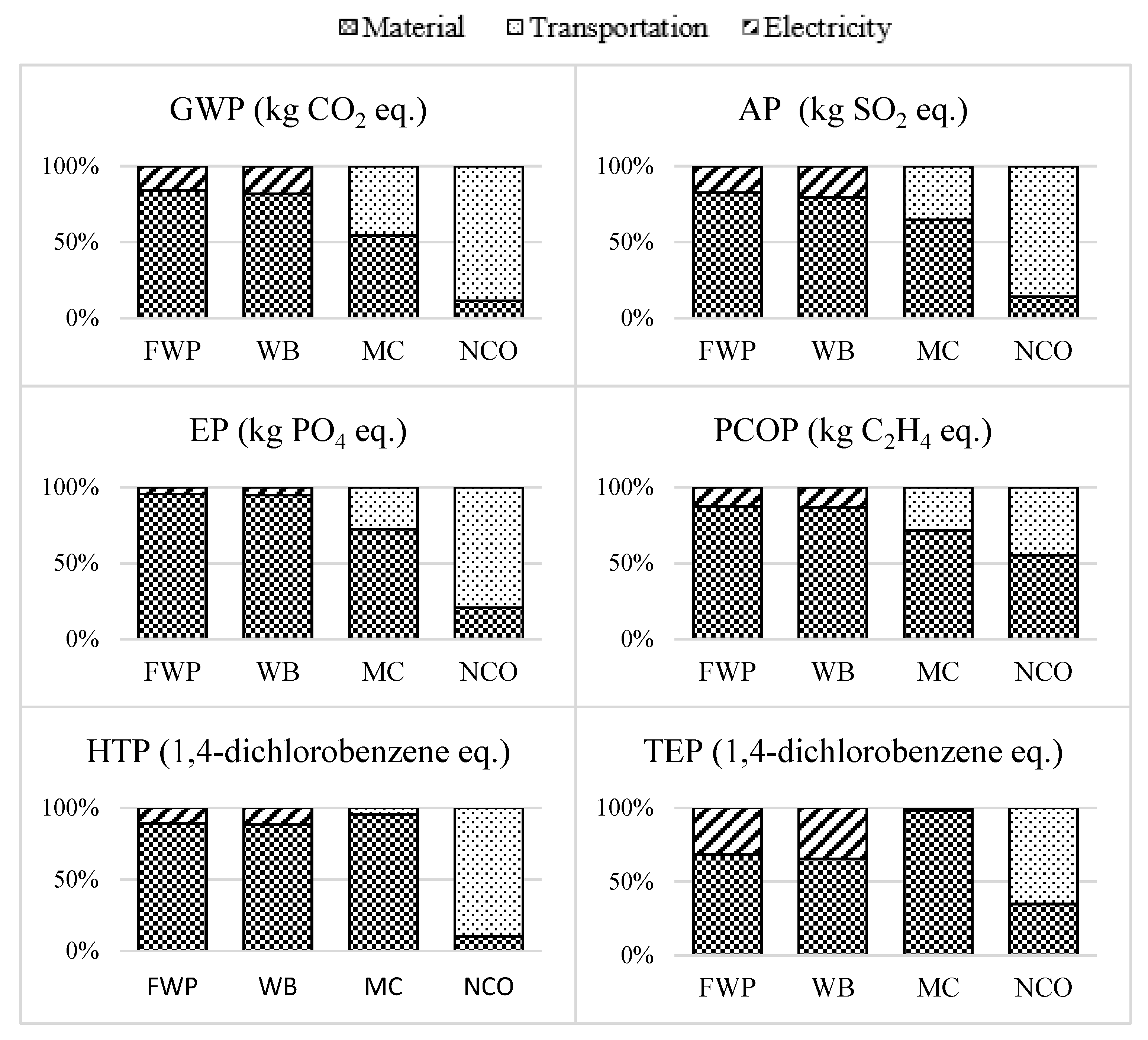
3.3.1. LCA Data and Results

The summarized LCA results corresponding to material, transportation, and electricity are presented in Table 3 and Figure 4. The results indicate that NCO has higher environment impact in the GWP, AP, PCOP, and EP categories. Transportation is contributing the most towards the above-mentioned impact categories. In addition to transportation, material consumption also has a significant contribution. Environmental impacts of MC are dominant in the HTP and TEP categories. FWP has the least environmental impact in all impact categories. In general, electricity has a very small contribution to any chosen impact category. Among two repair techniques applying welding, WB has a higher impact as compared to FWP due to increased consumption of material and electricity for the welding process.
Transportation used for NCO contributes a significant impact to GWP, AP, EP, and HTP. Whereas, transportation used for MC does not make any remarkable contribution in all impact categories except GWP. However, materials used in MC have a high contribution as compared to other inputs in all impact categories and are dominant in HTP and TEP. To sum up, transportation of NCO and materials used in MC are mainly responsible for high environmental impacts. Materials and electricity used in WB and FWP have a small impact compared to the inputs used in other repair techniques.

3.3.2. Discussion

Taking environmental impacts into consideration, FWP is the best process for repairing an externally corroded oil and gas pipe. It requires welding with the least number of passes on the periphery of steel plates, which reduces the consumption of filler metal, shielding gas, and electricity, and overall weld volume as compared to weld buildup. The main reason for low environmental impact is the fewer resources used in this repair technique. There is no such material in these techniques which is causing the harmful effect on the environment as compared to the other repair techniques. Due to the design of FWP, electricity consumption is also very small. However, in the case of WB, it is comparatively high due to a long process time. The WB repair process also has a significantly low environmental impact as compared to NCO and MC. However, it is high from FWP in all impact categories. The reason is that filler metals, shielding gas, and electricity consumption are high in WB. FWP consumed 97% less filler metal, 50% less shielding gas, and 50% less electricity than WB.
The NCO and MC repair techniques have greater consumption of resources due to which their environmental impacts are high. Hence, the LCA results represent clear environmental preference, and the fillet welded patch is the most environment-friendly repair solution for repairing small local wall thinning defects due to external corrosion. This study compared the environmental impacts of four repair techniques and showed that the environmental impacts are different for these techniques. The results of this study can help to consider environmental impacts along with cost as one of the factors while selecting a particular repair procedure. This study also highlights environmental hotspots in various repair techniques. By focusing on these hotspots, the environmental impacts of these techniques can be reduced.
The limitations of the current study need to be acknowledged due to challenges inherent in the LCA procedure [39,40]. LCA results suffer from variation in techniques used for impact assessment, different LCA software giving different results from the same data, lack of inventory data, and role of assumptions made during the goal and scope phase of the study [39]. Regarding our analysis, if the repair will be onsite, the impact will be different. The results of this study are valid for this defect type and size, as mentioned in the paper. The first reason is that, due to changes in defect size, the design and dimensions of the repair processes might be changed according to ASME PCC-2 standard. Secondly, it can also be possible that some other repair processes need to be preferred over current processes because fillet welded patch and weld buildup are normally used for small defect sizes and are not suitable for large defects [3]. However, composite overwrap has a broad scope—it can be used for any defect type and size according to ASME PCC-2 [5]. Furthermore, the testing procedure of the repair techniques has not been included in the scope of study, which may have some environmental impact.

4. Conclusions

This paper presents an assessment of the environmental impacts associated with the four main techniques used by the oil and gas industry to repair pipelines. These include fillet welded patch (FWP), weld buildup (WB), mechanical clamp (MC), and non-metallic composite overwrap (NCO). In this respect, six environmental impact categories (GWP, AP, EP, PCOP, HTP, TEP) are used to compare these repair processes. LCA of these four processes demonstrates that NCO has higher environmental impacts compared to MC, FWP, and WB processes. For a given defect size, NCO consumes much more material as compared to other processes. In addition, transportation of NCO material contributes significantly towards the environmental impacts. The consumption of stainless steel material in MC has a higher impact in HTP and TEP categories as indicated by sensitivity analysis. Environmental impacts of the welding repair techniques are comparatively low as compared to NCO and MC. The impact due to electricity consumption is almost negligible. FWP is the most environment-friendly repair solution among the four repair techniques due to less resource consumption. Based upon the results from this study, it can be suggested that environmental impacts of NCO and MC should be considered before applying them for repairing a pipe. Materials and transportation of these materials account for the bulk of environmental impacts of these processes. Future work should consider the influence of defect size and end-of-life scenarios on environmental impacts of these processes. Additionally, the role of corrosion protection coatings [41] and their interaction with repair methods can also be considered as an interesting field of study. Furthermore, the effect of end-of-life scenarios for various repair techniques can also be included in LCA.

Author Contributions

Conceptualization, M.M.S.; formal analysis, F.A.; methodology, S.P.; supervision, M.A.; revisions, M.M. All authors have read and agreed to the published version of the manuscript.

Funding

This research received no external funding.

Institutional Review Board Statement

Not applicable.

Informed Consent Statement

Not applicable.

Data Availability Statement

Not applicable.

Acknowledgments

The authors would like to acknowledge the support of the King Fahd University of Petroleum and Minerals (DSR project FT131004) in obtaining pipe samples for this project.

Conflicts of Interest

The authors declare no conflict of interest.

References

  1. Duell, J.M.; Wilson, J.M.; Kessler, M.R. Analysis of a carbon composite overwrap pipeline repair system. Int. J. Press. Vessel. Pip. 2008, 85, 782–788. [Google Scholar] [CrossRef]
  2. Beavers, J.A.; Thompson, N.G.; Technologies, C. External Corrosion of Oil and Natural Gas Pipelines. ASM Handb. 2006, 13, 1015–1026. [Google Scholar] [CrossRef]
  3. Antaki, G.A. Piping and Pipeline Engineering, Design, Construction, Maintenance, Integrity and Repair; Marcel Dekker: New York, NY, USA, 2003. [Google Scholar]
  4. Mableson, A.R.; Dunn, K.R.; Dodds, N.; Gibson, A.G. A New Composite—Based Repair Technique for Metallic Tubular. In Proceedings of the Eighth International Conference on Fibre Reinforced Composites, Newcastle Upon Tyne, UK, 13–15 September 2000; pp. 438–446. [Google Scholar]
  5. ASME. ASME PCC-2: Repair of Pressure Equipment and Piping. Asme 2008, 2008, 240. [Google Scholar]
  6. Chen, C.; Li, C.; Reniers, G.; Yang, F. Safety and security of oil and gas pipeline transportation: A systematic analysis of research trends and future needs using WoS. J. Clean. Prod. 2021, 279, 123583. [Google Scholar] [CrossRef]
  7. An international standard for disclosure of clinical trial information. BMJ 2006, 332, 1107. [CrossRef] [Green Version]
  8. ISO 14044:2006; Environmental Management—Life Cycle Assessment—Principles and Framework. ISO: Geneva, Switzerland, 2006. [CrossRef]
  9. Chang, Y.; Schau, E.; Finkbeiner, M. Application of life Cycle Sustainability Assessment to the Bamboo and aluminum Bicycle in surveying Social Risks of developing Countries. In Proceedings of the The 2ndWorld Sustainability Forum, Web Conference, 1–30 November 2012. [Google Scholar]
  10. Guinée, J.B.; Heijungs, R.; Huppes, G.; Zamagni, A.; Masoni, P.; Buonamici, R.; Ekvall, T.; Rydberg, T. Life cycle assessment: Past, present, and future. Environ. Sci. Technol. 2011, 45, 90–96. [Google Scholar] [CrossRef]
  11. Martínez, E.; Jiménez, E.; Blanco, J.; Sanz, F. LCA sensitivity analysis of a multi-megawatt wind turbine. Appl. Energy 2010, 87, 2293–2303. [Google Scholar] [CrossRef]
  12. Das, S. Life cycle assessment of carbon fiber-reinforced polymer composites. Int. J. Life Cycle Assess. 2011, 16, 268–282. [Google Scholar] [CrossRef]
  13. Elduque, D.; Javierre, C.; Pina, C.; Martínez, E.; Jiménez, E. Life cycle assessment of a domestic induction hob: Electronic boards. J. Clean. Prod. 2014, 76, 74–84. [Google Scholar] [CrossRef]
  14. Puri-Mirza, A. Middle East: Length of Midstream Oil and Gas Pieps by Country 2019 Statista. Available online: https://www.statista.com/statistics/1124254/middle-east-length-of-midstream-oil-and-gas-pipes-by-country/ (accessed on 26 May 2022).
  15. Sproesser, G.; Chang, Y.J.; Pittner, A.; Finkbeiner, M.; Rethmeier, M. Life Cycle Assessment of welding technologies for thick metal plate welds. J. Clean. Prod. 2015, 108, 46–53. [Google Scholar] [CrossRef]
  16. Drakopoulos, S.; Salonitis, K.; Tsoukantas, G.; Chryssolouris, G. Environmental Impact of Ship Hull Repair. Int. J. Sustain. Manuf. 2006, 1, 361–374. [Google Scholar] [CrossRef] [Green Version]
  17. Bosworth, M.R. Effective heat input in pulsed current gas metal arc welding with solid wire electrodes. Weld. J. 1991, 5, 111s. [Google Scholar]
  18. Wei, H.; Zhang, Y.; Tan, L.; Zhong, Z. Energy efficiency evaluation of hot-wire laser welding based on process characteristic and power consumption. J. Clean. Prod. 2015, 87, 255–262. [Google Scholar] [CrossRef]
  19. Spiegel-Ciobanu, V.E.P.G.H.C. Comparative Investigations in Order to Characterise Ultrafine Particles in Fumes in the Case of Welding and allied Processes. Weld. Cut. 2013, 12, 97–105. [Google Scholar]
  20. Vimal, K.E.K.; Vinodh, S.; Raja, A. Modelling, assessment and deployment of strategies for ensuring sustainable shielded metal arc welding process—A case study. J. Clean. Prod. 2015, 93, 364–377. [Google Scholar] [CrossRef]
  21. Zukauskaite, A.; Mickeviciene, R.; Karnauskaite, D.; Turkina, L. Environmental and human health issue of welding in the shipyard. In Proceedings of the 17th International Conference, Kaunas, Lithuania, 24–25 October 2013. [Google Scholar]
  22. Favi, C.; Germani, M.; Campi, F.; Mandolini, M.; Manieri, S.; Marconi, M.; Vita, A. Life Cycle Model and Metrics in Shipbuilding: How to Use them in the Preliminary Design Phases. In Proceedings of the Procedia CIRP, Stockholm, Sweden, 16–18 May 2018; Volume 69, pp. 523–528. [Google Scholar]
  23. Sproesser, G.; Chang, Y.-J.; Pittner, A.; Finkbeiner, M.; Rethmeier, M. Energy efficiency and environmental impacts of high power gas metal arc welding. Int. J. Adv. Manuf. Technol. 2017, 91, 3503–3513. [Google Scholar] [CrossRef]
  24. Chang, Y.-J.; Sproesser, G.; Neugebauer, S.; Wolf, K.; Scheumann, R.; Pittner, A.; Rethmeier, M.; Finkbeiner, M. Environmental and Social Life Cycle Assessment of welding technologies. In Proceedings of the Procedia CIRP, Sydney, Australia, 7–9 April 2015; Volume 26, pp. 293–298. [Google Scholar]
  25. Sangwan, K.S.; Herrmann, C.; Egede, P.; Bhakar, V.; Singer, J. Life Cycle Assessment of Arc Welding and Gas Welding Processes. In Proceedings of the Procedia CIRP, Stuttgart, Germany, 25–27 May 2016; Volume 48, pp. 62–67. [Google Scholar]
  26. Schmidt, W.P.; Beyer, H.M. Life cycle Study on a Natural Fibre Reinforced Component. In SAE Technical Papers; SAE International: Warrendale, PA, USA, 1998; p. 339. [Google Scholar]
  27. Corbière-Nicollier, T.; Gfeller Laban, B.; Lundquist, L.; Leterrier, Y.; Manson, J.A.; Jolliet, O. Life cycle assessment of biofibres replacing glass fibres as reinforcement in plastics. Resour. Conserv. Recycl. 2001, 33, 267–287. [Google Scholar] [CrossRef]
  28. Katz, A. Environmental Impact of Steel and Fiber–Reinforced Polymer Reinforced Pavements. J. Compos. Constr. 2004, 8, 481–488. [Google Scholar] [CrossRef] [Green Version]
  29. Maxineasa, S.G.; Taranu, N.; Bejan, L.; Isopescu, D.; Banu, O.M. Environmental impact of carbon fibre-reinforced polymer flexural strengthening solutions of reinforced concrete beams. Int. J. Life Cycle Assess. 2015, 20, 1343–1358. [Google Scholar] [CrossRef]
  30. Ahmed, I.M.; Tsavdaridis, K.D. Life cycle assessment (LCA) and cost (LCC) studies of lightweight composite flooring systems. J. Build. Eng. 2018, 20, 624–633. [Google Scholar] [CrossRef]
  31. Vidal, R.; Moliner, E.; Martin, P.P.; Fita, S.; Wonneberger, M.; Verdejo, E.; Vanfleteren, F.; Lapeña, N.; González, A. Life Cycle Assessment of Novel Aircraft Interior Panels Made from Renewable or Recyclable Polymers with Natural Fiber Reinforcements and Non-Halogenated Flame Retardants. J. Ind. Ecol. 2018, 22, 132–144. [Google Scholar] [CrossRef] [Green Version]
  32. Nguyen, L.; Hsuan, G.Y.; Spatari, S. Life Cycle Economic and Environmental Implications of Pristine High Density Polyethylene and Alternative Materials in Drainage Pipe Applications. J. Polym. Environ. 2017, 25, 925–947. [Google Scholar] [CrossRef]
  33. Abu Dabous, S.; Ghenai, C.; Shanableh, A.; Al-Khayyat, G. Comparison between major repair and replacement options for a bridge deck life cycle assessment: A case study. In Proceedings of the MATEC Web of Conferences, Sharjah, United Arab Emirates, 18–20 April 2017; Volume 120. [Google Scholar]
  34. Bizjak, K.F.; Knez, F.; Lenart, S.; Slanc, K. Life-cycle assessment and repair of the railway transition zones of an existing bridge using geocomposite materials. Struct. Infrastruct. Eng. 2017, 13, 331–344. [Google Scholar] [CrossRef]
  35. Liu, Z.; Jiang, Q.; Li, T.; Dong, S.; Yan, S.; Zhang, H.; Xu, B. Environmental benefits of remanufacturing: A case study of cylinder heads remanufactured through laser cladding. J. Clean. Prod. 2016, 133, 1027–1033. [Google Scholar] [CrossRef]
  36. ISO 14224:2016; Petroleum, Petrochemical and Natural Gas Industries—Collection and Exchange of Reliability and Maintenance Data for Equipment. BSI Standards Publication: London, UK, 2016. [CrossRef]
  37. Pre Consultants. SimaPro Database Manual; PRé Sustainability: Amersfoort, The Netherlands, 2017. [Google Scholar] [CrossRef]
  38. European Commission, Joint Research Centre—Institute for Environment and Sustainability. International Reference Life Cycle Data System (ILCD) Handbook—General guide for Life Cycle Assessment—Detailed Guidance; European Commission: Brussels, Belgium, 2010; ISBN 978-92-79-19092-6. [Google Scholar]
  39. Finkbeiner, M.; Ackermann, R.; Bach, V.; Berger, M.; Brankatschk, G.; Chang, Y.-J.; Grinberg, M.; Lehmann, A.; Martínez-Blanco, J.; Minkov, N.; et al. Challenges in Life Cycle Assessment: An Overview of Current Gaps and Research Needsx. In Background and Future Prospects in Life Cycle Assessment; Kl€opffer, W., Ed.; Springer: Berlin/Heidelberg, Germany, 2014; pp. 207–258. [Google Scholar]
  40. Curran, M. Strengths and Limiations of LCA. In Background and Future Prospects in Life Cycle Assessment; Klopffer, W., Ed.; Springer: Berlin/Heidelberg, Germany, 2014; pp. 207–258. [Google Scholar]
  41. Yeganeh, M.; Omidi, M.; Rabizadeh, T. Anti-corrosion behavior of epoxy composite coatings containing molybdate-loaded mesoporous silica. Prog. Org. Coat. 2019, 126, 18–27. [Google Scholar] [CrossRef]
Figure 1. Machined pipe defect to simulate external corrosion.
Sustainability 14 09499 g001
Figure 2. Repaired pipes using four repair techniques (a) FWP (b) WB (c) MC (d) NCO.
Sustainability 14 09499 g002aSustainability 14 09499 g002b
Figure 3. System boundary for the repair processes.
Sustainability 14 09499 g003
Figure 4. Relative contribution of material, transportation, and electricity.
Sustainability 14 09499 g004
Table 1. Pipe and defect size.
DimensionSize
Outer diameter (D)168.3 mm
Inner diameter (d)154.4 mm
Length of pipe (L)1000 mm
Defect length80 mm
Defect width20 mm
Defect depth2.5 mm
Table 2. Measured inventory data for all repair processes.
Inventory ItemFWPWBMCNCO
Filler material consumption (g)6250------
Shielding gas consumption (g)226.8453.6------
Energy consumption (kWh)0.1280.324------
Steel plate (g)65---------
Acetone (mL)5050100100
Water (g)---------1000
Glass fiber (g)---------1600
Epoxy (g)---------188
Polyethylene plastic (g)---------10
Steel clamp (g)------3120---
NBR gasket (g)------750---
Transportation (tkm)------13.2 a61.6 b
a: from Turkey, b: from USA.
Table 3. Environmental impacts of repair processes.
FWPWBMCNCO
GWP (kg CO2 eq.) 0.73571.624231.664476.1174
AP (kg SO2 eq.)0.00420.00910.15480.2965
EP (kg PO4 eq.)0.00120.00270.03840.0627
PCOP (kg C2H4 eq.)0.00020.00060.00820.0242
HTP (kg 1,4-dicholorobenzene eq.)0.20630.4881246.211456.6210
TEP (kg 1,4-dicholorobenzene eq.)0.00140.00320.31640.0351
Publisher’s Note: MDPI stays neutral with regard to jurisdictional claims in published maps and institutional affiliations.

