Article

Dynamic Response Characteristics and Damage Evolution of Multi-Layer Combined Coal and Rock Mass under Impact Loading

1
School of Emergency Management and Safety Engineering, China University of Mining and Technology (Beijing), Beijing 100083, China
2
CNOOC Research Institute Co., Ltd., Beijing 100028, China
*
Author to whom correspondence should be addressed.
Sustainability 2022, 14(15), 9175; https://doi.org/10.3390/su14159175
Submission received: 15 June 2022 / Revised: 23 July 2022 / Accepted: 25 July 2022 / Published: 26 July 2022
(This article belongs to the Special Issue Sustainable Mining and Emergency Prevention and Control)

Abstract

:
The areas involved in coal and gas outbursts are composed of multi-layer coal and rock mass, in which external dynamic disturbance propagates in the form of stress waves; therefore, reflection, transmission and diffraction occur at the interfaces, resulting in dynamic effects such as reflected tension, convergence and superposition of stress and strain, and sudden changes of reflected and transmitted stress, which are the key factors leading to the outburst. Based on the Split Hopkinson Pressure Bar system, the dynamic time–history changes of stress, strain and strain rate of five-layer combined coal and rock mass were studied under impact loading. The results show that the time–history curves of stress and strain could be divided into five stages and that of strain rate three stages; the dynamic curves of the five stress–strain stages were significantly different between high-velocity and low-velocity impact. It was hypothesized that under high-speed impact loading, the mechanical anisotropy of combined coal and rock mass at the linear elastic stage tends to be isotropic. Based on ANSYS LS-DYNA, the damage evolution and failure process of five-layer combined coal and rock mass were simulated and analyzed under impact loading. It is concluded that the initial positions of damage of each layer were located at the circle center and its vicinity; radial cracks were mainly formed under low-speed impact loading, and circumferential cracks were mainly formed under high-speed impact loading. In the propagation and action of loading and unloading waves, the “weak layer” was damaged first by tensile stress and formed a free surface, and the subsequent loading waves were reflected on the free surface to form unloading waves and tensile stress, resulting in damage and spalling in multi-layer coal and rock mass.

1. Introduction

The coal and rock mass involved in coal and gas outbursts has different mechanical properties and discontinuous spatial distribution, such that this area is composed of multi-layer combined coal and rock mass [1]. Mining and excavation disturbances are the main external dynamic sources to induce outburst [2,3]; the progressive damage and instability of coal and rock mass in outburst preparation and excitation are the joint actions of external disturbance and in situ stress to multi-layer combined coal and rock mass. Under external disturbance, coal and rock mass shows strong dynamic response characteristics, and the dynamic mechanical properties and failure modes are significantly different from those under static load [4,5,6]. When the local disturbance stress is higher than the tensile strength, damage and fracture occur in the corresponding areas, forming macro cracks, resulting in the instability and failure of coal and rock mass [7]. In addition, external dynamic disturbance propagates in multi-layer combined coal and rock mass in the form of stress waves; therefore, reflection, transmission and diffraction occur at the interfaces of coal–rock, rock–rock and coal–coal, resulting in reflected tension, convergence and superposition of stress and strain, and sudden changes of reflected and transmitted stress, which could lead to strong vibration, dynamic damage and instability and failure of coal and rock mass, which are the key factors leading to the outburst [8,9]. Spallation is a typical phenomenon in coal and gas outburst, which is closely related to the whole process of outburst, including preparation, initiation, development and termination. Scholars usually regarded the coal and rock mass in front of cross-cut coal uncovering and tunneling face as a combined multi-layer coal and rock mass, and they established the seepage instability and unloading wave action models [10]; they believed that the interaction of unloading waves forms high tensile stress at the interfaces with large differences in mechanical properties, resulting in sudden instability and failure of coal and rock mass [11,12], which may be closely related to the spallation phenomenon. At present, the layered coal and rock mass is usually regarded as a transversely isotropic continuum, and the damage mechanism of single-layer coal and rock mass were studied based on Euler formula, compression bar stability theory, the Mohr Coulomb yield criterion and the flexural failure mechanical model [13,14,15,16,17,18]. However, the research on the dynamic response characteristics, and the damage and failure modes of multi-layer combined coal and rock mass is still in the initial exploration stage [19,20,21,22].
Based on the Split Hopkinson Pressure Bar experimental system, the dynamic time–history changes of stress, strain and strain rate of five-layer combined coal and rock mass without confining pressure were studied under relative low/high-velocity impact loading to reveal the dynamic response characteristics and failure modes of combined coal and rock mass. Based on ANSYS LS-DYNA, the dynamic damage evolution and failure processes of multi-layer combined coal and rock mass were simulated and analyzed. The generation of spallation and the process of coal and gas outburst under loading and unloading waves are discussed.

2. Experimental Preparation

2.1. Preparation of Multi-Layer Combined Coal and Rock Specimens

All types of coal and rock specimens used in the experiment were processed from large raw coal and rock, and similar specimens were from the same raw coal and rock. Therefore, it was considered that the mechanical properties of the same type coal and rock specimens are roughly the same. The coal and rock specimens were cylindrical and φ 50 mm × 10 mm in size, which ascertained the cleanliness of specimens’ surface during specimen processing and the error was ±0.02 mm. There were five types of coal and rock in the experiment, including coal, siltstone, limestone, shale and white sandstone. The combined coal and rock specimens consisted of five single-layer coal and rock specimens, which were divided into four groups according to different combination sequences which were used in the experiment without confining pressure, as shown in Figure 1. A total of 20 single-layer coal and rock specimens were prepared.
L stands for limestone, SI for siltstone, S for shale, C for Coal, W for white sandstone. The combination sequences of combined coal and rock specimens were as follows:
(1)
Group 1st (L–SI–S–C–W): limestone—L1, siltstone—SI1, shale—S1, coal—C1, white sandstone—W1;
(2)
Group 2nd (L–C–S–SI–W): limestone—L2, coal—C2, shale—S2, siltstone—SI2, white sandstone—W2;
(3)
Group 3rd (SI–S–C–L–W): siltstone—SI3, shale—S3, coal—C3, limestone—L3, white sandstone—W3;
(4)
Group 4th (SI–L–C–S–W): siltstone—SI4, limestone—L4, coal—C4, shale—S4, white sandstone—W4.

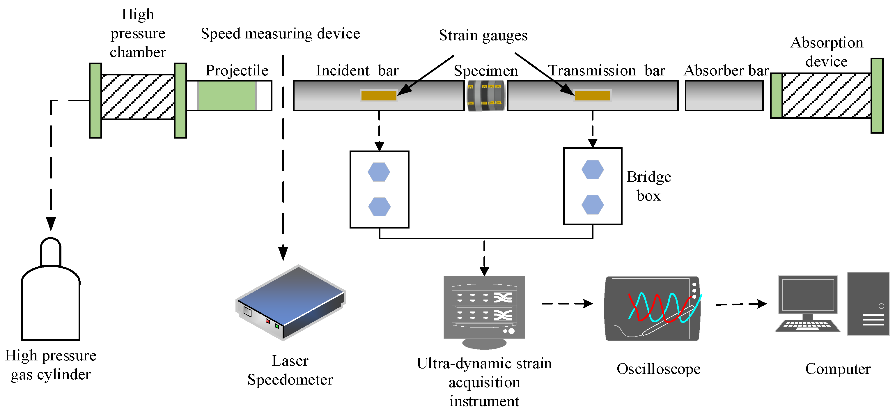
2.2. SPHB Impact Test System

Based on the φ 50 mm SHPB impact test system [23,24,25], as shown in Figure 2, dynamic impact experiments for four groups of multi-layer combined coal and rock mass without confining pressure were carried out, respectively, with an aluminum short-size cylindrical bullet. The impact loading was applied to the coal and rock specimens by driving the air pressure and giving the bullet impact velocity to hit the incident bar; the distance between the bullet and the air pressure point were adjusted to 40 cm, 80 cm, 120 cm, 160 cm and 200 cm, respectively, to obtain different impact velocities.
The bullet impact velocity was measured by the laser velocimeter, and the strain pulse signal by the strain gauge on the incident and the transmission bars. The signal was amplified by the super dynamic strain gauge and then stored by the transient waveform memory; the sampling frequency was set to 1 MHz, which met the transient test standard. The strain pulse signal was synchronously triggered by the super dynamic strain gauge, and the strain values of coal and rock specimens were collected by the data acquisition instrument (DH9560). Eight test channels were used in the experiment, including 1#, 2#, 3# and 4# channels for axial strain and 5#, 6#, 7# and 8# channels for radial strain. In order to avoid the error influence of sensitivity and resistance of the strain gauge, the impact calibration test was carried out before the test; the strain ε was compared with the voltage value U measured by the super-dynamic strain gauge, and the proportional relationship between strain and voltage was: K = ε/U = 1.94792 × 10⁻⁴. Based on the proportional relationship between strain and voltage, the incident strain εi, reflection strain εr and transmission strain εt was obtained from the voltage value U obtained by the impacting specimen. Based on the calculation in Equation (1) of the one-dimensional stress hypothesis, the stress σ, strain ε and strain rate ε ˙ of coal and rock specimens were determined. In the SHPB experimental system, the elastic modulus of the incident and transmission bars E = 206 GPa, the wave velocity C0 = 5060 m/s, the total thickness of multi-layer combined coal and rock specimens L = 50 mm, and the cross-sectional areas of the bar and specimen A0 and A = 625 π mm2.
{ σ = E A A 0 ε t ε = 2 C 0 L 0 t ε t dt ε ˙ = 2 C 0 L ε t

3. Analysis of Experimental Results

3.1. Dynamic Mechanical Characteristics of Multi-Layer Combined Coal and Rock Specimens without Confining Pressure under Impact Loading

3.1.1. Time–History Dynamic Curves of Stress and Strain

The extreme and peak points of stress and strain of multi-layer combined coal and rock specimens under high-velocity impact (impact velocities were between 6.225 and 6.538 m/s) and their occurrence times are shown in Table 1, and the dynamic curves between stress and time in Figure 3a. Due to the disconnection of the test equipment during the experiment, the mechanical dynamic states of Group 1st under low-velocity impact and Group 3rd under high-velocity impact were not verified. These curves were similar and could be roughly divided into five stages as follows (taking the results of the impact velocity of 6.414 m/s as an example):
(1)
Stage I—compaction stage (0–0.04 ms), the stress value rose slightly to about 2.4 MPa;
(2)
Stage II—sharp rise in linearity (0.04–0.075 ms), the stress value rose rapidly to 19.8 MPa;
(3)
Stage III—continuous rise with nonlinearity (0.075–0.11 ms), the stress value continued to rise to the peak point of 21.6 MPa accompanied by prominent oscillation, which was more significant than that with confining pressure. At this stage, one or several layers of coal and rock mass were suddenly damaged or even failed;
(4)
Stage IV—first unloading (0.11–0.15 ms), the stress decreased rapidly to 10.4 MPa;
(5)
Stage V—second unloading (0.15–0.20 ms), the stress decreased steadily to 8.6 MPa.
Similarly, the dynamic curves between strain and time under high-velocity impact, as shown in Figure 3b, were also similar and could also be divided into five stages (take the impact velocity of 6.414 m/s as an example):
(1)
Stage I—compaction stage (0–0.1 ms), the strain increased slowly to 0.82‰;
(2)
Stage II—sharp rise in linearity (0.10–0.13 ms), the strain increased sharply to 2.7‰, which indicated that one or several layers of coal and rock mass had been seriously damaged or failed;
(3)
Stage III—continuous rise with nonlinearity (0.13–0.18 ms), the strain increased continuously to the peak point of 4.2‰;
(4)
Stage IV—first rebound (0.18–0.21 ms), the strain dropped rapidly to 3.9‰;
(5)
Stage V—second rebound (0.21–0.30 ms), the strain gently reduced to 3.5‰.
The time–history curves of stress and strain under low-velocity impact (impact velocity was between 2.365 and 2.945 m/s) were consistent with the conclusions drawn by other researchers. Since the specimens did not have significant damage or failure, there was no obvious nonlinear plastic change.

3.1.2. Stress–Strain Dynamic Curves

The stress–strain curves of multi-layer combined coal and rock specimens under high-velocity impact could also be divided into five stages, as shown in Figure 4a,b:
(1)
OA section—compaction stage, the gaps, micro cracks and pores of multi-layer combined coal and rock mass specimens were compacted;
(2)
AB section—linear elastic stage, the stress increased linearly with the increase of strain, and the lines of different impact velocities almost coincided at this stage, indicating that the elastic modulus of combined coal and rock specimens were roughly equal;
(3)
BC section—nonlinear plastic stage, the curves of stress–strain showed a nonlinear change trend, and the stress increased gently to the peak point with the strain;
(4)
CD section—unloading stage, the stress began to decrease, and the strain continued to increase;
(5)
DE section—rebound stage, the stress and strain significantly reduced, showing a rapid rebound phenomenon.
The results show that the stress–strain curves of combined coal and rock under low-velocity impact loading (2.365–2.945 m/s, Figure 4c) were similar to that under static load (except the rebound stage) [20]. Moreover, under high-velocity impact loading (6.225–6.538 m/s), the stress–strain curves decreased instantaneously at point B (Figure 4a), which was divided into the point of the linear elastic stage and nonlinear plastic stage, and it indicated that impact loading led to damage in one or several layers. At the linear elastic stage, the stress–strain curves of combined coal and rock mass in different combination sequences almost coincided, and the curve trends at other stages were similar and had an obvious rebound phenomenon. The distribution of mechanical properties along the axial direction of four groups of combined coal and rock masses with different combination sequences must be different, but the stress–strain curves at the elastic stage (AB segment) in Figure 4a almost coincided, and it may be concluded that the mechanical anisotropy of combined coal and rock mass at the linear elastic stage is weakened or even disappears, and tends to be isotropic under high-speed impact loading.

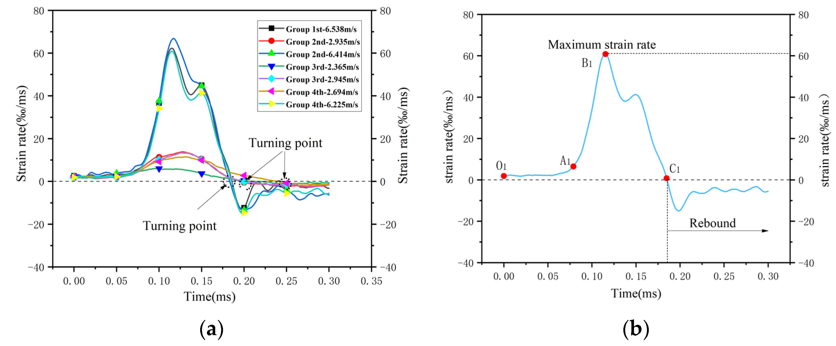
3.1.3. Time–History Dynamic Curves of Strain Rate

The axial strain curve of multi-layer combined coal and rock specimens without confining pressure under high-velocity impact are shown in Figure 5; it could also be divided into positive and negative stages. To be specific, firstly, the positive stage included three processes: (1) the initial and linear elastic stage—O1A1 (0–0.08 ms), the strain rate was relatively stable; (2) plastic stage—A1B1 (0.08–0.115 ms), the strain rate increased sharply to the peak point; (3) unloading stage—B1C1 (0.115–0.18 ms), the strain rate began to decrease. Secondly, in terms of the negative stage, the strain rate changed from positive to negative after the turning point C1 (0.18 ms), showing a significant rebound phenomenon. The time–history curve of strain rate under low-velocity impact could also be divided into positive stages and negative stages.

3.2. Dynamic Failure Modes of Multi-Layer Combined Coal and Rock Mass under Impact Loading

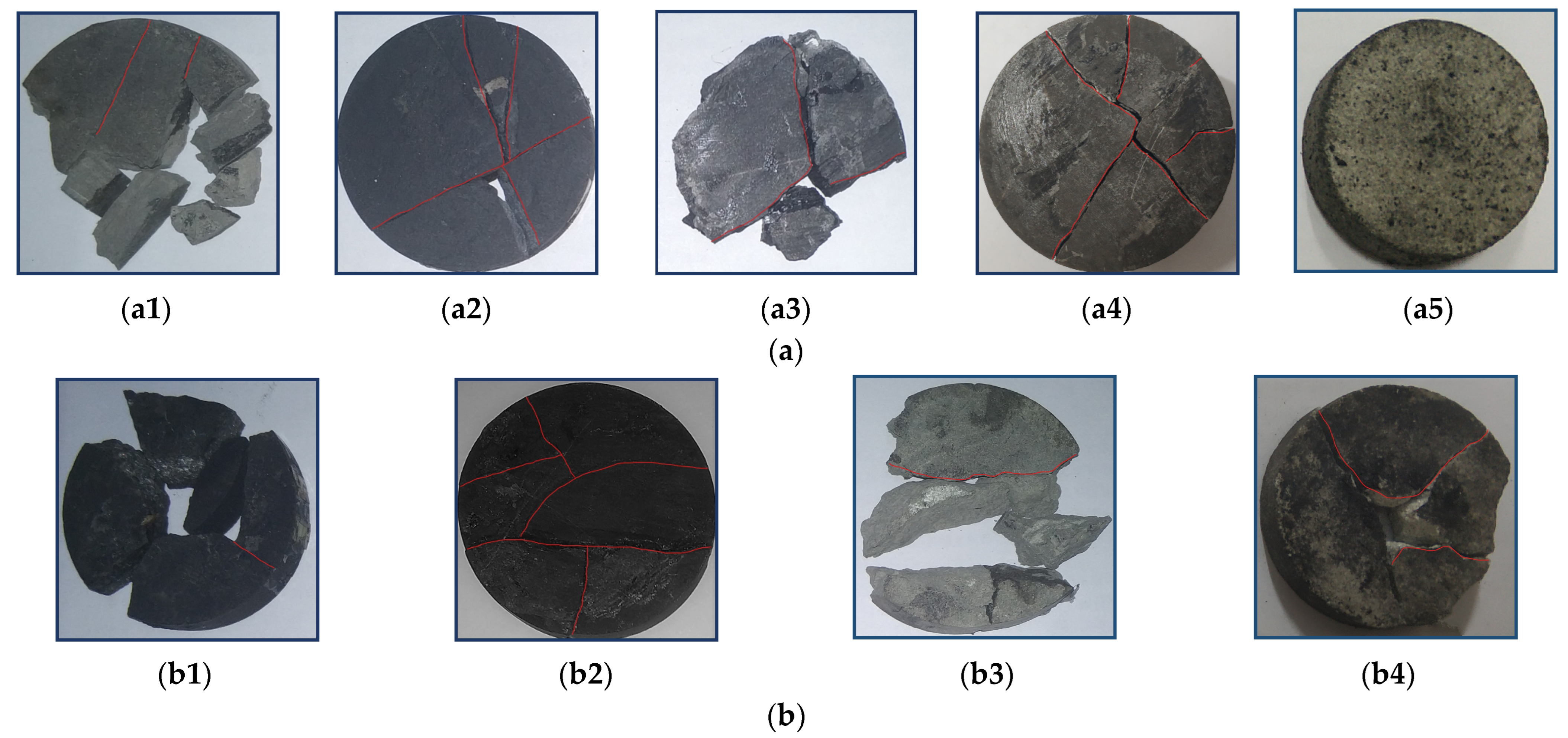
3.2.1. Dynamic Failure Modes of Combined Coal and Rock Mass

The dynamic failure modes of each layer of combined coal–rock specimens are shown in Figure 6. Under low-speed impact loading (2.945 m/s), the white sandstone was not damaged, and the coal and siltstone were damaged first in the 3rd group of combined coal and rock mass (SI–S–C–L–W), as shown in Figure 6a. The initial positions of the damage of coal and rock mass in each layer were the circle center and its vicinity. The crack extended radially and penetrated the whole coal and rock sample, forming obvious tensile failure. Under high-speed impact loading (6.414 m/s), the coal sample was damaged first in the 2nd group of combined coal and rock mass (L–C–S–SI–W), followed by siltstone and limestone, and finally white sandstone and shale, as shown in Figure 6b. The initial positions of the damage were also the circle center and its vicinity, and combined with failure modes, it was observed that there should be circumferential cracks, in addition to radial cracks.

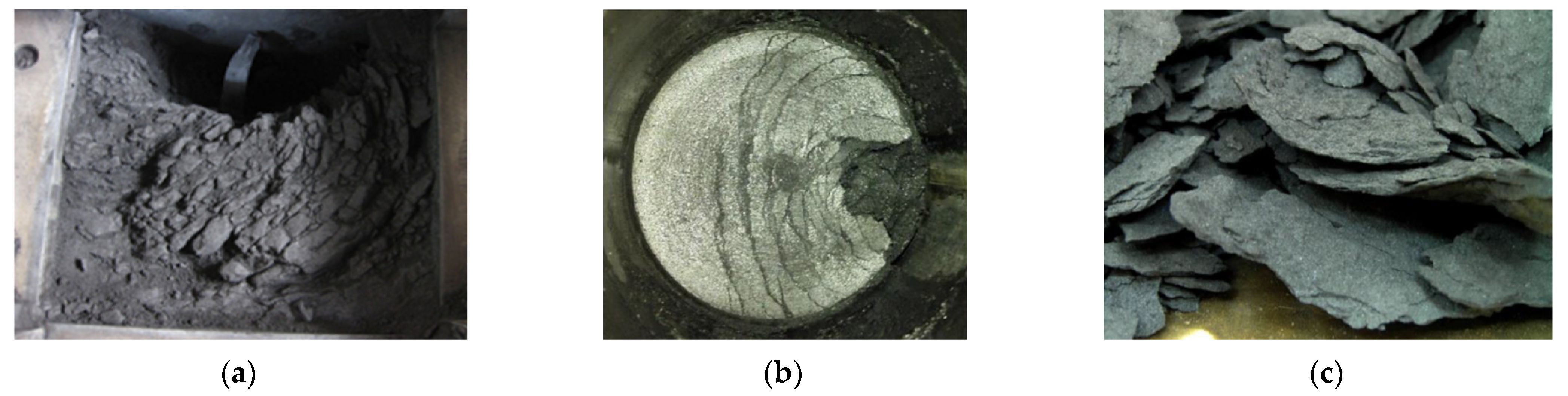
3.2.2. Dynamic Damage Evolution of Coal and Rock Mass in Each Layer

Based on ANSYS LS-DYNA, the interfaces of coal–rock and rock–rock were set as erosion contact, and the transverse friction was ignored; the relevant mechanical parameters are shown in Table 2. The dynamic damage and failure evolution of each layer of combined coal and rock mass were simulated and analyzed with linear elastic and principal stress failure models, as shown in Figure 7 and Figure 8.
Under low-speed impact loading (2.945 m/s), the coal sample in the 3rd group was damaged and destroyed first at 0.092~0.1 ms, followed by siltstone, limestone and shale (Figure 7). The initial positions of damage in each layer of coal and rock mass were the circle center and its vicinity, and the cracks expanded radially and penetrated the coal and rock mass to cause brittle failure, which was consistent with the experimental results (Figure 6a).
Under high-speed impact loading (6.414 m/s), the coal sample in the 2nd group was also damaged and destroyed first at 0.071~0.075 ms (Figure 8), and the stress decreased instantaneously, corresponding to points P1 (Figure 3), B (Figure 4) and B1 (Figure 5). Then, limestone, siltstone, shale and white sandstone were damaged (points P2, P3 and BC) and destroyed, leading to stress relief (points P3, CD and B1C1), and radial and circumferential cracks appeared on the surfaces of the coal and rock samples, which was consistent with the experimental results (Figure 6b).
The results of this research show that fragments of white sandstone, shale and limestone were relatively large, but that of coal and siltstone were small with serious damage. It verified that the “weak layer” is damaged or even fails first, and consumes the most energy. From the crack texture, the cracks mainly occurred on the center of the surface and developed along the radial and circumferential direction, showing a significant brittle failure. It was observed that the dynamic failure mode of multi-layer combined coal and rock mass without confining pressure was mainly tensile failure under impact loading.

4. Discussion

Scholars usually used a one-dimensional combined coal and rock mass model to study the spallation phenomenon in coal and gas outburst. They regarded the coal and rock mass in front of cross-cut coal uncovering and tunnelling face as multi-layer combined coal and rock mass with a fixed boundary. They believed that the unloading wave action or seepage instability were the key factors causing the damage and failure of coal and rock mass, finally resulting in spallation phenomenon, as shown in Figure 9 [26,27]. However, there is no analysis of the generation process of spallation, and its mechanism is still not clarified, which is essential for sustainable mining and the prevention of coal and gas outburst.
In cross-cut coal uncovering, the loading and unloading waves were formed by the external disturbance from mining and excavation activities, and propagate in each layer of coal and rock mass; the interface between plastic and elastic coal with the highest stress concentration can produce large tensile stress, which is prone to tensile failure [28]. Considering the stress distribution and damage state of the coal mass in front of the uncovering coal by rock crosscut, it was verified that the plastic coal body with the highest stress concentration and the state of ultimate equilibrium is a “weak layer”, as shown in Figure 10a.
In the propagation and interaction of loading and unloading waves, the “weak layer” was damaged first by tensile stress and formed a free surface, and the subsequent loading waves were reflected on the free surface to form unloading waves and tensile stress, resulting in damage and spalling along the axial direction (Figure 10b). Assuming that the loading wave was a rectangular wave, the spallation thickness should be half the wavelength. According to the actual situation, the longitudinal wave speed of the coal body was set to 1600 m/s, and the rectangular wave action time was about 0.036 ms (Figure 6); then the data calculated that the wavelength λ = 5.76 cm, and the thickness of the spalling fracture was 2.88 cm, which was consistent with field tests and experimental results [26]. In this process, under low-speed impact loading, the surface cracks mainly developed in the radial direction, as showed in Figure 11a; under high-speed impact loading, the circumferential boundary of the “weak layer” was prone to damage to form a free surface. Due to the Poisson effect, a significant lateral inertial effect was produced, i.e., lateral expansion and contraction, so as to generate compressive stress waves along the radial direction, and then these compressive stress waves were reflected on the free surface to form tensile stress waves, which gradually accumulated to the central point and became larger and larger, accordingly. During this process, if the tensile stress exceeded the tensile strength σs, circumferential cracks were formed (Figure 11b), the entire process of which is shown in Figure 11c. Eventually, circumferential and radial cracks (Figure 11d) were formed on the surface to generate spallation with a certain arc (Figure 9).
The entire process of “outburst” could be inferred as follows (Figure 10c): (1) Formation of the spalling area—outburst preparation. (2) Rapid gas desorption in the spalling areas and collection of gas seepage from the nearby area forms high-pressure gas in this area in a very short time, which expands fast and throws the coal and rock out, resulting in the outburst. At the same time, in situ stress and redistribution of deep coal bodies create a new “weak layer”. (3) The rapid formation, expansion and pressure reduction of high-pressure gas form fluctuating effects during outburst [29,30]. Similar to the action process of dynamic load disturbance, the fluctuating effects could also generate loading and unloading waves and propagate to the new “weak layer” and form new spalling areas, i.e., outburst development. Since the gas desorption and seepage to form high-pressure gas need to consume some time, the spalling and throwing of the coal layer are intermittent. (4) When there is no weak layer (encountering a hard coal rock mass) or the expansion energy of the high-pressure gas is not enough to throw the fractured coal mass, this results in outburst termination. In this process, a large part of the coal rock mass is damaged but not thrown, so the amount of gas desorption is much greater than the amount of gas adsorbed by the thrown coal body.

5. Conclusions

(1)
The time–history curves of stress and strain and the dynamic curves of stress–strain could be divided into five stages, and the time–history curves of strain rate could be divided into three stages, generally; the stress–strain curves under high-velocity impact were significantly different from that under low-velocity impact or static loading.
(2)
Under high-velocity impact, the mechanical anisotropy of multi-layer combined coal and rock mass with or without confining pressure had relatively little influence on the overall mechanical properties in the elastic stage. Therefore, it could be considered that the mechanical properties of multi-layer combined coal and rock mass with different combination sequences were isotropy along the axial direction (Impact direction) before severe damages or failures.
(3)
The initial positions of damage to the coal and rock mass in each layer were located at the circle center and its vicinity; under low-speed impact loading, radial cracks were mainly formed on the surface, and circumferential cracks were mainly formed under high-speed impact loading.
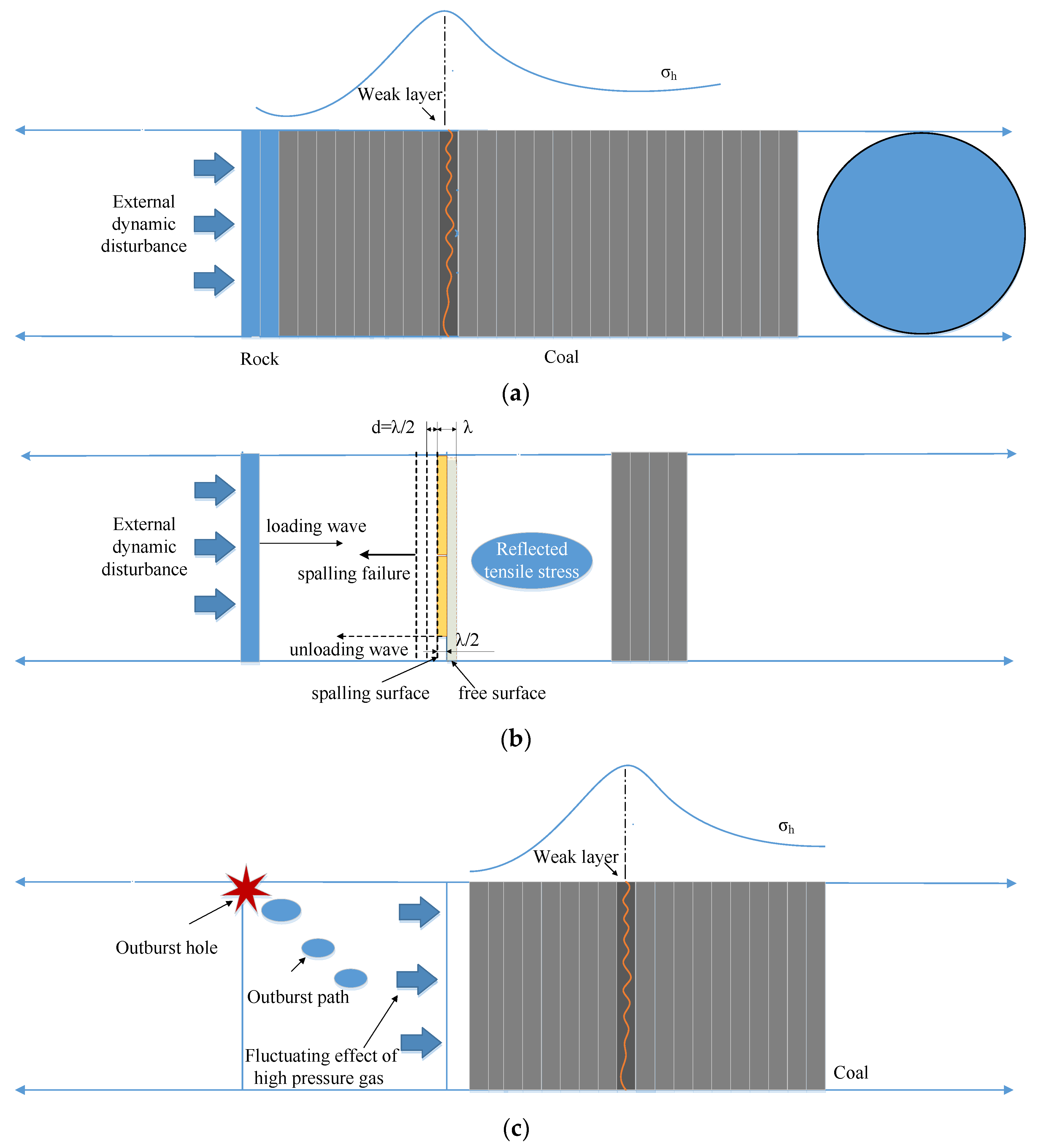
(4)
In the propagation and interaction of loading and unloading waves, the “weak layer” was damaged first by tensile stress and formed a free surface, and the subsequent loading waves were reflected on the free surface to form unloading waves and tensile stress, resulting in damage and spalling. In addition, the fluctuating effects of high-pressure gas in outbursts were the key factor for continuous spalling.

Author Contributions

F.L.: Investigation, formal analysis, funding acquisition, methodology, writing—original draft. R.S.: Supervision, writing—review and editing. Y.Z.: Investigation, writing—review and editing. G.W.: Data curation, supervision, writing—review and editing. G.X.: Investigation, methodology, validation. All authors have read and agreed to the published version of the manuscript.

Funding

The authors are grateful for the financial support from the National Natural Science Foundation of China (52064046, 51804311), the special project for regional collaborative innovation of Xinjiang Autonomous Region (Science and technology assistance plan for Xinjiang) (2020E0258), the China Scholarship Council (CSC) and the Fundamental Research Funds for the Central Universities (2020YJSAQ13).

Conflicts of Interest

The authors declare no conflict of interest.

References

  1. Shu, L.Y.; Wang, K.; Qi, Q.; Fan, S.; Zhang, L.; Fan, X. Disaster causation mechanism of key structures highlighted by coal and gas. Chin. J. Rock Mech. Eng. 2017, 36, 347–356. [Google Scholar] [CrossRef]
  2. Aguado, M.B.D.; Nicieza, C.G. Control and prevention of gas outbursts in coal mines, Riosa–Olloniego coalfield, Spain. Int. J. Coal Geol. 2007, 69, 253–266. [Google Scholar] [CrossRef]
  3. Xian, X.; Gu, M.; Li, X.; Jiang, D. Conditions for excitation and occurrence of coal with gas prominence. Geomech. Eng. 2009, 30, 577–581. [Google Scholar] [CrossRef]
  4. Li, X.B.; Gong, F.Q.; Gao, K.; Yin, S.B. Experimental study on rock impact failure under one-dimensional dynamic and static combination loading. Chin. J. Rock Mech. Eng. 2010, 29, 251–260. [Google Scholar]
  5. Jin, J.F.; Li, X.B.; Wang, G.S.; Yin, Z.Q. Sandstone failure mode and its mechanism under cyclic impact load. J. Cent. South Univ. 2012, 43, 1453–1461. [Google Scholar]
  6. Feng, J.; Wang, E.; Shen, R.; Chen, L.; Li, X.; Xu, Z. Investigation on energy dissipation and its mechanism of coal under dynamic loads. Geomech. Eng. 2016, 11, 657–670. [Google Scholar] [CrossRef]
  7. Jiang, Y.D.; Zhao, Y.X.; Song, Y.Q.; Liu, W.G.; Zhu, D.J. Analysis on the mechanism of power instability induced by firing shock in coal mine roadways. Chin. J. Rock Mech. Eng. 2005, 24, 3131–3136. [Google Scholar]
  8. Cai, F.; Liu, Z.G.; Luo, Y. Propagation and attenuation characteristics of detonation stress waves in high gas coal seams. J. Coal Soc. 2014, 39, 110–114. [Google Scholar] [CrossRef]
  9. Su, G.S.; Hu, L.H.; Feng, X.T.; Wang, J.; Zhang, X. True triaxial experimental study of rock burst process under the combined action of low-frequency periodic perturbation load and static load. Chin. J. Rock Mech. Eng. 2016, 35, 1309–1322. [Google Scholar] [CrossRef]
  10. Jin, H.W.; Hu, Q.T.; Liu, Y.B.; Wang, B. Mechanism study on the phenomenon of mid-stratocracking and impacting ground pressure. J. Min. Saf. Eng. 2012, 29, 694–699. [Google Scholar]
  11. Diederichs, M.; Kaiser, P. Tensile strength and abutment relaxation as failure control mechanisms in underground excavations. Int. J. Rock Mech. Min. Sci. 1999, 36, 69–96. [Google Scholar] [CrossRef]
  12. Li, F.; Zhang, Y.; Liu, J.; Zhang, L.; Fang, S. The dynamical response characteristics of elastic–plastic coal under dynamic load. J. Nat. Gas Sci. Eng. 2016, 29, 497–505. [Google Scholar] [CrossRef]
  13. Mei, S.H. Study on the Excavation Deformation Mechanism and Failure Mechanism of Layered Rock Mass. Ph.D. Dissertation, Graduate School of Chinese Academy of Sciences (Wuhan Institute of Geomechanics), Wuhan, China, 2008. [Google Scholar]
  14. Huang, S.L.; Xu, J.S.; Ding, X.L.; Wu, A.Q. Composite model and application of layered rock mass considering the characteristics of structural surface. Chin. J. Rock Mech. Eng. 2010, 29, 743–756. [Google Scholar]
  15. Huang, S.L.; Ding, X.L.; Wu, A.Q.; Lu, B.; Zhang, Y.H. Polynodal constitutive model and experimental verification of layered rock masses. Chin. J. Rock Mech. Eng. 2012, 31, 1627–1635. [Google Scholar]
  16. Lu, H.F.; Yao, D.X. Study on stress distribution law and failure depth of stratiform rock mass of mining bottom plate. Chin. J. Rock Mech. Eng. 2014, 33, 2030–2039. [Google Scholar] [CrossRef]
  17. Yang, R.S.; Zhu, Y.; Li, Y.L.; Li, Y.W. Stress distribution and damage failure characteristics of roadway bottom plate in layered rock mass. J. China Univ. Min. Technol. 2020, 49, 615–626, 645. [Google Scholar] [CrossRef]
  18. Bai, Q.; Dai, H.J. Numerical simulation of damage failure characteristics of stratiform rock mass. Bull. Yangtze River Acad. Sci. 2022, 39, 129–134, 140. [Google Scholar]
  19. Bailly, P.; Delvare, F.; Vial, J.; Hanus, J.; Biessy, M.; Picart, D. Dynamic behavior of an aggregate material at simultaneous high pressure and strain rate: SHPB triaxial tests. Int. J. Impact Eng. 2011, 38, 73–84. [Google Scholar] [CrossRef] [Green Version]
  20. Fakhimi, A.; Hemami, B. Axial splitting of rocks under uniaxial compression. Int. J. Rock Mech. Min. Sci. 2015, 79, 124–134. [Google Scholar] [CrossRef]
  21. Xie, B.J.; Wang, X.Y.; Lv, P.Y. Experiment on dynamic mechanical characteristics of impact failure of SHPB of laminar coal rock. Vib. Shock. 2017, 36, 117–124. [Google Scholar] [CrossRef]
  22. Liu, X.H.; Xue, Y.; Zhou, J.F.; Hao, Q.J.; Zheng, Y. Dynamic failure energy variation law and damage characteristics of laminar coal rock. Chin. J. Undergr. Space Eng. 2021, 17, 1052–1062. [Google Scholar]
  23. Forquin, P.; Nasraoui, M.; Rusinek, A.; Siad, L. Experimental study of the confined behaviour of PMMA under quasi-static and dynamic loadings. Int. J. Impact Eng. 2012, 40–41, 46–57. [Google Scholar] [CrossRef]
  24. Aben, F.; Doan, M.-L.; Gratier, J.-P.; Renard, F. High strain rate deformation of porous sandstone and the asymmetry of earthquake damage in shallow fault zones. Earth Planet. Sci. Lett. 2017, 463, 81–91. [Google Scholar] [CrossRef] [Green Version]
  25. Braunagel, M.J.; Griffith, W.A. The effect of dynamic stress cycling on the compressive strength of rocks. Geophys. Res. Lett. 2019, 46, 6479–6486. [Google Scholar] [CrossRef]
  26. Guo, P.K. Research on the Development Mechanism of Coal and Gas Protrusion Fracture. Ph.D. Dissertation, China University of Mining and Technology, Beijing China, 2014. [Google Scholar]
  27. Zhao, Z.G. Coupled Catastrophic Mechanism and Nonlinear Analysis of Coal and Gas Prominence. Ph.D. Dissertation, Shandong University of Science and Technology, Qingdao, China, 2007. [Google Scholar]
  28. Li, F.; Zhang, G.Y.; Fang, S.H.; Zhang, L.; Liu, J.R. Study on dynamic damage characteristics of elastic and plastic combined coal under impact load. J. Min. Saf. Eng. 2016, 33, 1096–1102, 1109. [Google Scholar]
  29. Xu, J.; Geng, J.B.; Peng, S.J.; Yuan, M.; Zhang, C.L.; Luo, X.H. Experimental study on the prominent pulsating development process of coal and gas. J. China Univ. Min. Technol. 2018, 47, 145–154. [Google Scholar] [CrossRef]
  30. Zhang, A.L.; Xie, H.P.; Zhang, R.; Ren, L.; Zhou, J.F.; Gao, M.Z.; Tan, Q. Dynamic failure behavior of Jinping marble under various preloading conditions corresponding to different depths. Int. J. Rock Mech. Min. Sci. 2021, 148, 104959. [Google Scholar] [CrossRef]
Figure 1. Multi-layer combined coal and rock specimen.
Sustainability 14 09175 g001
Figure 2. φ 50 mm SHPB impact test system.
Sustainability 14 09175 g002
Figure 3. Time–history curves of stress/strain of multi-layer combined coal and rock without confining pressure. (a) the dynamic curves between stress and time. (b) the dynamic curves between strain and time.
Sustainability 14 09175 g003
Figure 4. Stress–strain curves of multi-layer combined coal and rock under impact. (a) five stages. (b) stress–strain curves. (c) stress–strain curves under low speed impact.
Sustainability 14 09175 g004
Figure 5. Time–history curves of strain rate of multi-layer combined coal and rock under impact. (a) time—history curves. (b)three stages.
Sustainability 14 09175 g005
Figure 6. Failure modes of each layer of coal and rock mass under impact loading. (a) Failure modes of the 3rd group of coal and rock mass under low-speed impact loading (2.945 m/s). (a1) Siltstone. (a2) Shale. (a3) Coal. (a4) Limestone. (a5) White sandstone. (b) Failure modes of the 2nd group of coal and rock mass under high-speed impact loading (6.414 m/s). (b1) Limestone. (b2) Shale. (b3) Siltstone. (b4) White sandstone.
Sustainability 14 09175 g006
Figure 7. Dynamic damage and failure evolution of the 3rd group under low-speed impact loading (2.945 m/s). (a) Siltstone. (a1) 0.14 ms. (a2) 0.149 ms. (a3) 0.375 ms. (b) Shale. (b1) 0.108 ms. (b2) 0.14 ms. (b3) 0.273 ms. (c) Coal. (c1) 0.092 ms. (c2) 0.1 ms. (d) Siltstone. (d1) 0.136 ms. (d2) 0.172 ms. (d3) 0.236 ms.
Sustainability 14 09175 g007
Figure 8. Dynamic damage and failure evolution of the 2nd group under high-speed impact loading (6.414 m/s). (a) Limestone. (a1) 0.08 ms. (a2) 0.103 ms. (a3) 0.14 ms. (b) Coal. (b1) 0.071 ms. (b2) 0.075 ms. (c) Shale. (c1) 0.083 ms. (c2) 0.131 ms. (c3) 0.356 ms (d) Siltstone. (d1) 0.08 ms. (d2) 0.091 ms. (d3) 0.17 ms. (e) White sandstone. (e1) 0.095 ms. (e2) 0.111 ms. (e3) 0.175 ms. (f) radial and circumferential cracks. (f1) circumferential cracks. (f2) radial cracks. (f3) radial and circumferential cracks.
Sustainability 14 09175 g008
Figure 9. Spalling phenomenon and spalling fractures in coal and gas outburst. (a,b) cracks distribution (c) fracture characteristics.
Sustainability 14 09175 g009
Figure 10. The development of spalling under dynamic disturbance. (a) spalling condition. (b). spalling failure (c) spalling development.
Sustainability 14 09175 g010
Figure 11. Circumferential and radial cracks formed on the surface of the coal rock mass. (a) radial cracks. (b) circumferential cracks. (c) process of “outburst”. (d) radial and circumferential cracks.
Sustainability 14 09175 g011
Table 1. The extreme points and times of stress/strain of multi-layer combined coal and rock without confining pressure.
Impact Velocities
(m/s)
Extreme Points of StressPeak Points of Strain
1st Extreme Point/P12nd Extreme Point/P23rd Extreme Point/P3
Time/msStress/MPaTime/msStress/MPaTime/msStress/MPaTime/msStrain/‰
GP 1st—6.5380.076212.7520.09579.8090.111110.7890.18573.952
GP 2nd—2.9350.10926.326----0.19531.219
GP 2nd—6.4140.079319.8140.091019.0290.110121.5800.18324.285
GP 3rd—2.3650.12813.730----0.21190.664
GP 3rd—2.9450.10715.101----0.19741.153
GP 4th—2.6940.11023.727----0.23981.264
GP 4th—6.2250.080211.7700.087611.5740.111815.1060.18513.662
Table 2. Mechanical parameters of coal and rock mass.
TypeDensity (Kg/m−3)Elastic Modulus (GPa)Poisson’s RatioTensile Strength (MPa)Shear Strength (MPa)
Limestone2660350.187.9821
Coal14003.50.300.65
Shale2600400.129.1224
Siltstone2590200.2059
White sandstone2620370.148.5522.4
Publisher’s Note: MDPI stays neutral with regard to jurisdictional claims in published maps and institutional affiliations.

