Case Report

Mechanism Analysis of Roof Deformation in Pre-Driven Longwall Recovery Rooms Considering Main Roof Failure Form

1
School of Civil Engineering and Architecture, Xi’an University of Technology, Xi’an 710048, China
2
School of Architecture and Civil Engineering, Xi’an University of Science and Technology, Xi’an 710054, China
*
Author to whom correspondence should be addressed.
Sustainability 2022, 14(15), 9093; https://doi.org/10.3390/su14159093
Submission received: 24 May 2022 / Revised: 15 July 2022 / Accepted: 22 July 2022 / Published: 25 July 2022
(This article belongs to the Topic Mining Safety and Sustainability)

Abstract

:
Pre-driven recovery rooms are used extensively for the removal of mining equipment and hydraulic supports in longwall coal mining. Roof stability is a crucial factor influencing the speed and safety of the removal of operators in pre-driven recovery rooms. The characterization of roof deformation mechanisms in recovery rooms under front abutment pressures is significant for surrounding rock control and stability evaluation. In this study, three different roof subsidence evaluation models, considering different main roof failure forms, were established. It was noticed that the main roof break position had a significant effect on recovery room roof sag. The breaking of the main roof above the main recovery room and protective coal pillar was found to be the main driving force for large roof deformations. Furthermore, field monitoring data of roof sag and coal pillar stress in the 15205 and 15206 panels of Hongliulin Coal Mine were analyzed. According to evaluation models and field monitoring data, we propose determination methods for the evaluation of recovery room roof sag and main roof break position. During the study it was found that the inversion results of the main roof break position of the recovery room in 15205 and 15206 panels were 4.2 m and 9.1 m, respectively, which are basically consistent with the results calculated by periodic weighting. The research findings provide a reference for the quantitative evaluation of recovery room roof stability and the design of support parameters and yield mining.

1. Introduction

Pre-driven recovery room technology is a commonly applied equipment removal method in longwall fully mechanized faces. It was first tested and popularized in the United States in the late 1980s [1,2,3]. In this method, one or two roadways are excavated parallel to the longwall face and approach the terminal line in advance to provide space for equipment removal and the use of trackless rubber-tired mine cars to transport equipment. In the process of the gradual popularization of this technology, some researchers have studied pre-driven recovery room support design methods and developed support technology that includes single hydraulic props or concrete pillars combined with bolts and cables [4,5,6,7,8,9,10,11]. After the initial support of the recovery room with bolts and cables, a reinforcement support is constructed as the longwall face approaches 200 m from the terminal line. Single hydraulic props or concrete pillars can be used to reinforce and support recovery rooms. This support method has been widely used in the recovery rooms of many coal mines since the 1990s. Since the beginning of the 21st century, high resistance hydraulic supports have been extensively employed for roof support in many coal mines, some of which have used chock hydraulic supports for reinforcement of recovery room supports and to replace single hydraulic props and concrete pillars. This support method has significantly improved control of the surrounding rock and the safety degree of recovery rooms [12,13,14].
Research on the support technology and design methods of pre-driven recovery rooms has formed a relatively mature system. Meanwhile, several achievements have been made in studies on the ground, strata and support responses of recovery rooms at the end of mining stage and the deformation laws of the surrounding rock of recovery rooms has been basically determined. Based on a large number of field monitoring and case studies, researchers have qualitatively determined the factors affecting the surrounding rock stability of recovery rooms [15,16,17]. The obtained results show that the surrounding rock deformation of pre-driven recovery rooms was large in the middle and small at opposite ends and the main roof failure mode is the key factor determining the roof deformation and stability. Further, support intensity, overburden depth, mining height, width of coal pillar, etc. has affected the surrounding rock stability in recovery rooms [18,19,20,21,22,23,24,25]. Furthermore, according to overburden theory, some researchers have studied the load and stability of the coal pillars of recovery rooms and have revealed the instability mechanism of unmined coal pillars in longwall faces and protective coal pillars between the main and secondary recovery rooms, developing corresponding coal pillar design methods [26,27,28,29,30,31]. However, although these studies have determined the surrounding rock deformation law of pre-driven recovery rooms and solved coal pillar design problems to a certain extent, it is obvious that our understanding of surrounding rock deformation and failure of recovery rooms is still qualitative rather than quantitative. For example, many field-monitoring projects and case studies have focused on support technology, most of which have suggested that the break position of the main roof was the main factor determining recovery room roof stability. However, there is still lack of comprehensive mechanical models to explain the quantitative relationship between main roof break position and roof sag of recovery rooms. In addition, as one of the main measures in controlling roof deformation, the quantitative relationship between support intensity and recovery room roof deformation also needs to be studied. So far, some researchers have established mechanical models for recovery room roof sag by using cantilever beam theory [32]; however, such a simple model cannot explain large roof deformations in some recovery rooms. Therefore, in many mining areas, due to the inability of quantitative calculation and evaluation of recovery room roof deformation, some coal mines have formulated inappropriate support and removal schemes, resulting in support crushing accidents. Such accidents frequently occur in many mining areas with favorable geological and mining conditions, which also indicates that the roof deformation and stability evaluation of recovery rooms is still a problem that needs to be solved. Shennan mining area is located in Shenfu-Dongsheng Coalfield at the junction of Inner Mongolia and Shaanxi province in China, which is an area with typical shallow coal seams. Shallow burial, small dip angle and simple geological structures are the typical features of coal seam occurrence in this mining area. Recently, high-strength chock hydraulic supports have been applied to surrounding rock supports in pre-driven recovery rooms. However, by using such advanced production equipment and simple geological mining conditions, large roof deformations of the recovery rooms frequently occur, resulting in serious support crushing accidents which threaten the safety of operators and equipment. Figure 1 shows large roof deformations and hydraulic support crushing accidents of a pre-driven recovery room in a typical shallow longwall panel in Shennan mining area. In the figure, shield hydraulic supports with maximum working resistance of 9000 kN were used in the longwall face and chock hydraulic supports with maximum working resistance of 12,000 kN were used in the recovery room. However, roof sag still exceeded 1.2 m and the main recovery room height was reduced from 3.5 m to just over 2.0 m. Such excessive roof deformations reduced the stroke of most shield and chock hydraulic support columns to below 100 mm and in some cases, even to 0; dozens of hydraulic supports were even crushed. In these hydraulic support crushing accidents at the end of longwall face mining stage, although the main recovery room roof sag exceeded 1.2 m, the roof sags of headgate and tailgate did not exceed 40 mm, indicating that surrounding rock deformation and failure mechanisms of recovery room were more complex than other mining roadways arranged along the face advancing direction. Therefore, it is necessary to determine roof deformation mechanisms in recovery rooms and estimate and identify main roof break positions.
In this study, roof deformation and coal pillar stress analyses of recovery rooms in two adjacent longwall panels in Hongliulin Coal Mine were performed. Three different roof sag evaluation models for recovery rooms considering different main roof failure forms were established and the roof sag variation law of recovery rooms was analyzed. From the case studies and theoretical analysis results obtained for two adjacent panels of Hongliulin Coal Mine in Shennan mining area, the inversion discrimination method of the main roof break position in the recovery room was established based on theoretical and experimental data of roof sag and coal pillar stress. According to this inversion discrimination method, along with periodic weighting observations at the end of the mining stage, the main roof break position was identified, and a basis was provided for formulating surrounding rock control measures for recovery rooms during equipment removal stage under different roof failure forms.

2. Case Study

2.1. Roof and Coal Seam Conditions

Table 1 summarizes the roof lithology and occurrence conditions of 5−2 coal seam. The average thicknesses of 5−2 coal seam was 7.23 m and was therefore classified as a thick coal seam. The immediate and main roofs of the 5−2 coal seam were mainly composed of sandstone with high strength and thickness. The average depth of the 5−2 coal seam at the recovery room was about 150 m. The roof in Shennan mining area had good stability, was easy to maintain and did not usually cause large roof deformations and collapse.

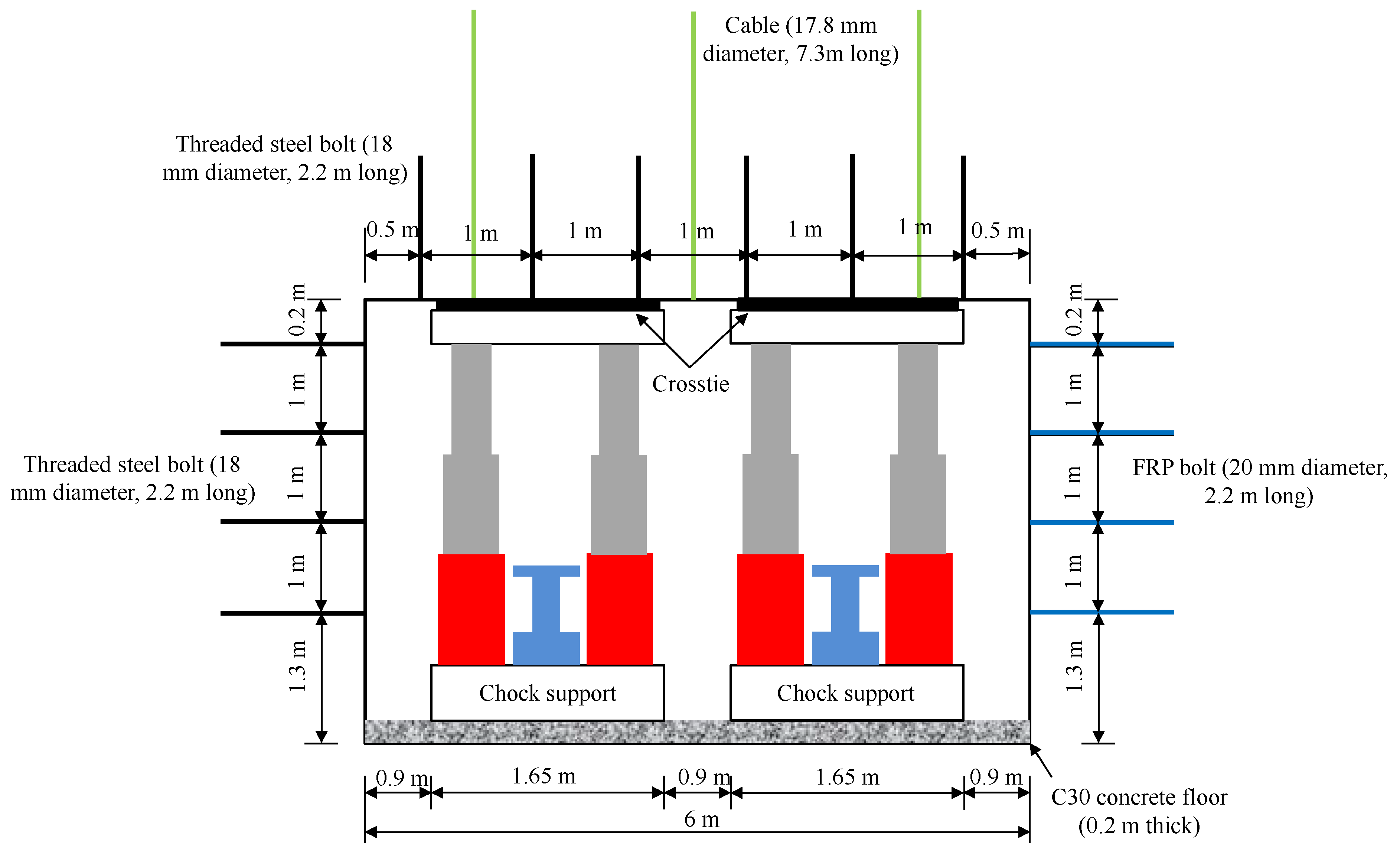
2.2. Support and Mining Conditions

Both panels 15205 and 15206 used pre-driven double recovery rooms. Support patterns in the main recovery rooms of the two panels are given in Table 2. The recovery room was supported by bolts, cables, and hydraulic supports. Initial supports included bolts and cables and two rows of chock hydraulic supports were installed as reinforcement support before the longwall face entrance into the main recovery room.
The support parameters and mining conditions of the two panels are illustrated in Table 3. The length of the recovery room in both panels was 300 m. The width of coal pillar between the main and secondary recovery rooms was 20 m. The maximum working resistances of shield and chock hydraulic supports in the two panels were 17,000 kN and 18,000 kN, respectively. Figure 2 shows a plan view of the support design for the main recovery room.

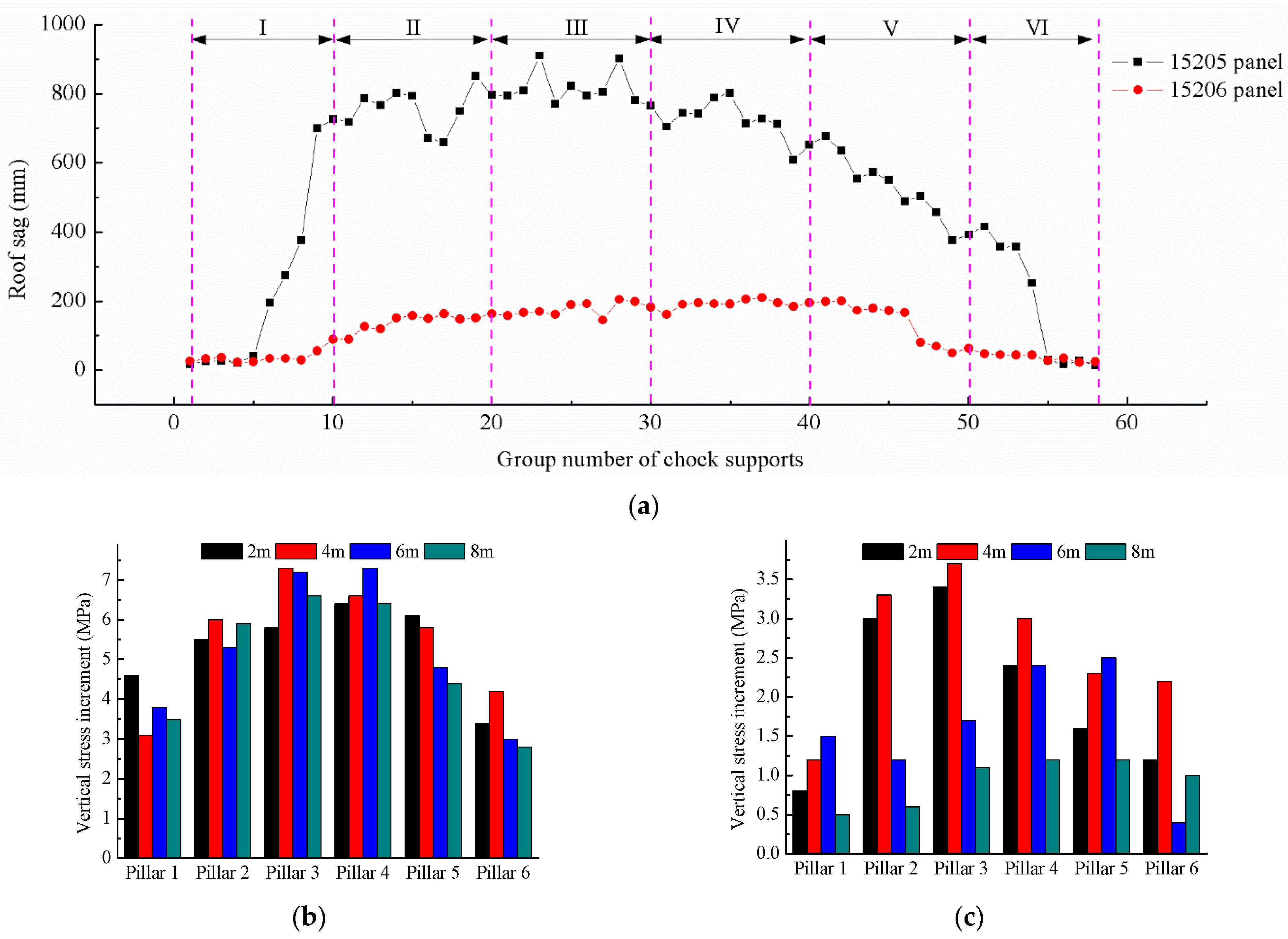
2.3. Field Monitoring

Previous studies have shown that recovery room roof deformation presented significant non-uniformity with a large deformation in the middle and small deformations at opposite ends. Therefore, according to the longwall face dip length of the 5−2 coal seam in Hongliulin coal mine, the main recovery room was divided into six roof deformation and six protective coal pillar stress monitoring areas, as shown in Figure 3. Recovery room roof sag was characterized by canopy-to-base convergence of chock supports. The average canopy-to-base convergence of the two chock support rows was taken and measured by a laser range finder. Coal pillar stress changes were monitored by HCZ-2 borehole pressure cells which were installed at depths of 2, 4, 6, and 8 m. The monitoring results of roof sag and coal pillar stress in panels 15205 and 15206 are illustrated in Figure 4.
The monitoring results presented in Figure 4 reveal that the deformations of surrounding rocks around the recovery room in panels 15205 and 15206 were quite different. The maximum recovery room roof sag in panel 15205 was four times higher than that in panel 15206 and was even larger than 900 mm in the third monitoring area. Coal pillar stress monitoring results also reveal that the overall increase of coal pillar stress in the recovery room of panel 15205 was large, and the increase of coal pillar stress in the middle was higher than 5 MPa. However, the overall increase of coal pillar stress in the recovery room of panel 15206 was small and the maximum increase of coal pillar stress in the middle was only 3 to 3.5 MPa with small stress changes in the deep part of coal pillar, which indicate little disturbance in the elastic zone of coal pillar.
Roof sag monitoring data obtained from the middle of the recovery rooms of panels 15205 and 15206 are presented in Figure 5. It was observed that recovery room roof sags of the two panels were greatly increased near the entrance of the longwall face. The difference was that, beyond the entrance of the longwall face in panel 15205, recovery room roof sag continued to increase by about 42 mm, while the corresponding value for panel 15206 was relatively smaller. This shows that the roof of the recovery room in panel 15205 was still in a state of dynamic change after mining was stopped, which is unfavorable for roof control in the process of hydraulic support removal.
Figure 6 shows coal pillar failure in the recovery rooms of panels 15205 and 15206. In panel 15206, only a spalling failure in the lower part of the coal pillar with dirt band and unsupported areas was observed while in panel 15205, the whole middle and lower parts of the coal pillar bulged out and some supporting structures such as bolts and joists were also damaged and failed.
Based on the above results, it was concluded that although there were no roof fall accidents in the two monitored panels, there was a great risk of excessive roof deformation in the recovery room of panel 15205. According to the classification of surrounding rock stability of coal mine roadways in China, mining roadways with roof sags exceeding 400 mm were in an unstable state [33,34], as presented in Table 4. From roof sag monitoring results, it was found that the recovery room in panel 15205 was basically in an extremely unstable state, which greatly increased safety risk during equipment removal process and made recovery room maintenance difficult; therefore, temporary reinforcement support was required. For the recovery room in panel 15206, with an overall roof sag of about 200 mm, surrounding rock was relatively stable. This meant there was no need to add extra temporary supports during the equipment removal process, which not only enhanced removal speed, but also reduced safety risk. Hence, for pre-driven longwall recovery room, if roof sag limit value could be controlled at 100–400 mm, equipment could be safely and quickly removed.

3. Mechanical Model of Roof Deformation of Pre-Driven Recovery Room

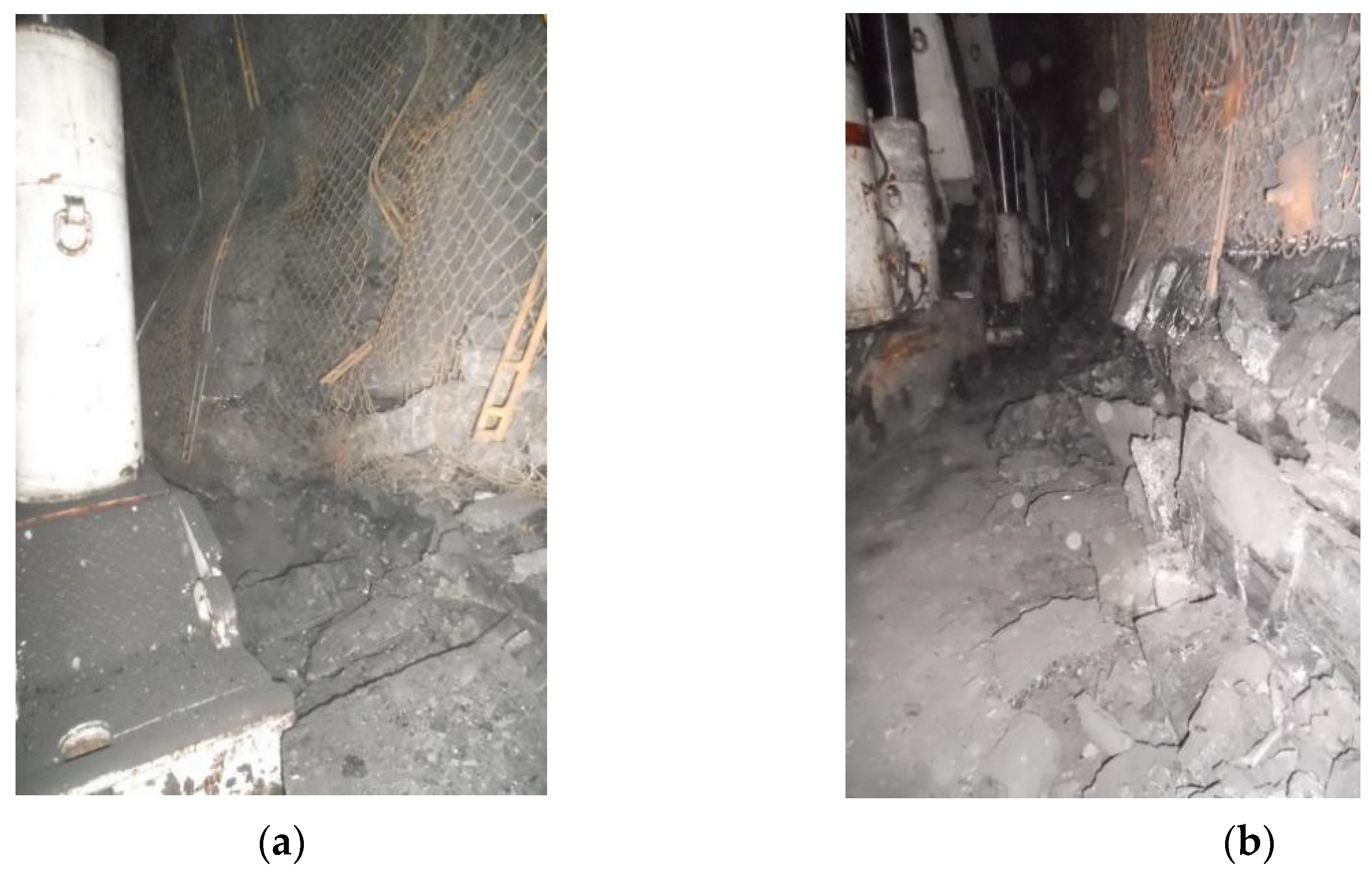
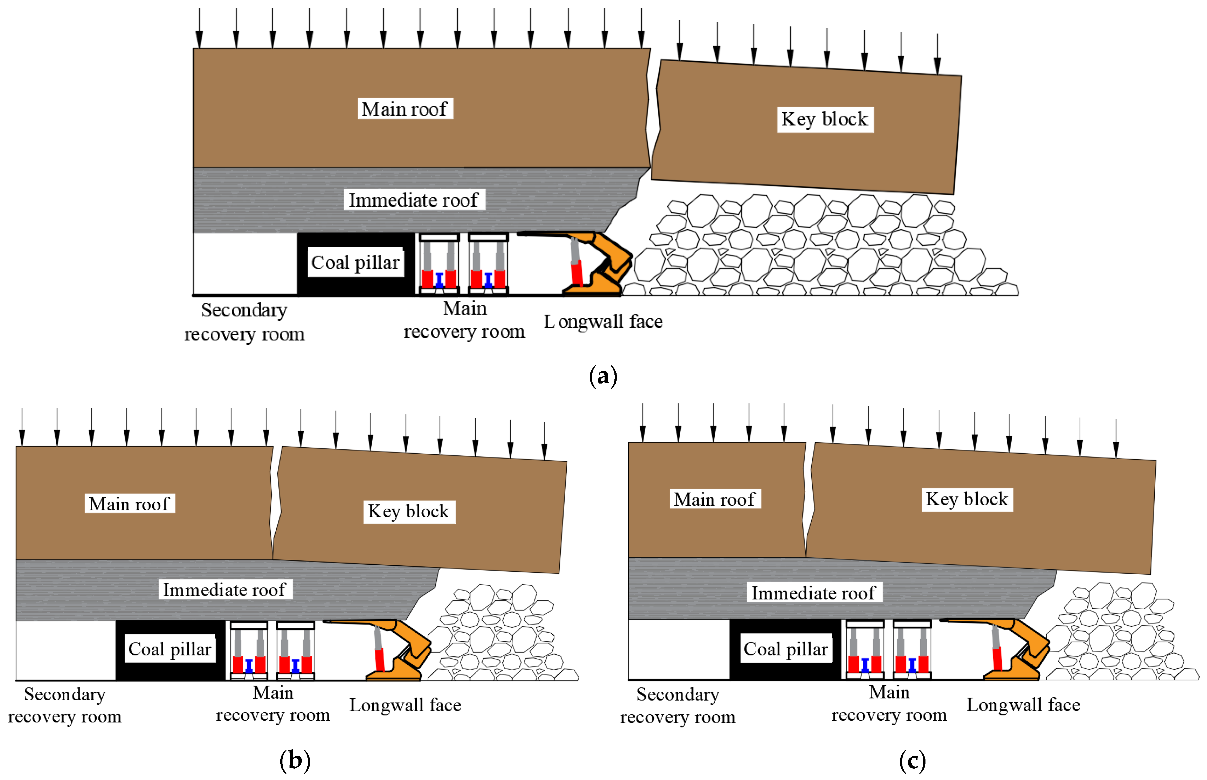
3.1. Roof Failure Form in Recovery Room

Based on strata behavior observations in Chinese mining practices, when a longwall face enters a recovery room, the main roof could continue to break and collapse. Depending on the main roof break position following the entrance of the longwall face into the main recovery room, three forms of main roof failure can occur [22,24,27,35,36,37], as shown in Figure 7.
From the three main roof failure forms, the second and third forms were not conducive to equipment removal. As shown in Figure 7a, when the main roof breaks behind the hydraulic supports of the longwall face, the roof forms a cantilever rock beam. It is obvious that the roof is in a relatively complete and stable state and only flexural deformations occur, which are conducive to hydraulic support removal. As shown in Figure 7b,c, when the main roof breaks above the main recovery room or protective coal pillar, the entire, or a part, of the recovery space becomes unstable. After primary removal of some chock or shield hydraulic supports, supporting intensity reduction leads to further rotation of the key block and roof sag continues to increase, making the removal of remaining hydraulic supports potentially difficult. On the other hand, some case studies have also shown that the breaking of the main roof behind the longwall face hydraulic supports does not necessarily ensure recovery room roof stability. When support strength was insufficient or cantilever rock beam was too long, the main roof broke again, changing from the failure form in Figure 7a to those presented in Figure 7b,c.

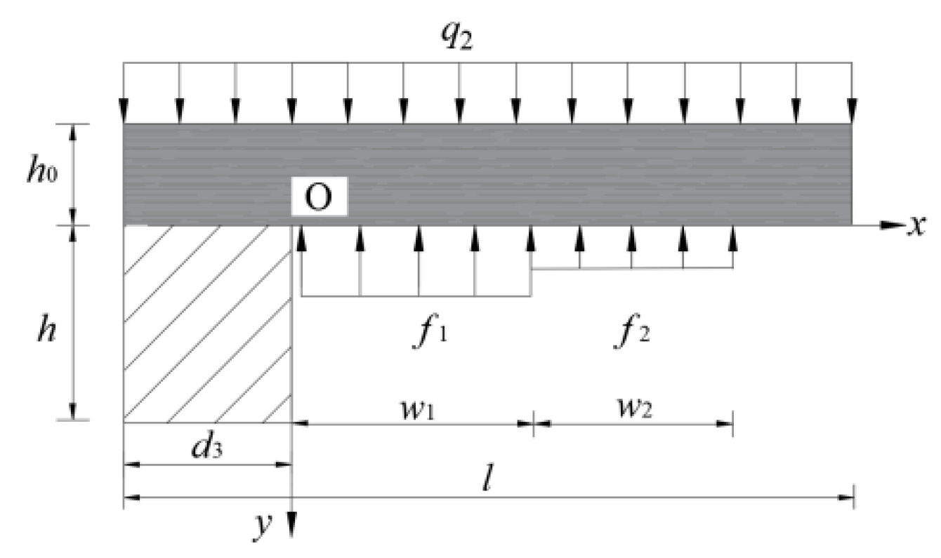
3.2. Establishing Mechanical Models

3.2.1. Main Roof Breaks behind Shield Hydraulic Supports

When the main roof breaks behind the shield hydraulic supports, the recovery room roof takes on a cantilever beam structure since the mining rib is completely mined. If the breaking of the cantilever rock beam does continue, immediate roof deflection could be considered as recovery room roof sag. The upper part of the immediate roof bears front abutment pressure and hydraulic supports directly supported the roof. The developed mechanical model is shown in Figure 8 where q1 is front abutment pressure; f1 and f2 are supporting intensities of chock and shield hydraulic supports, respectively; w1 and w2 are the widths of main recovery room and longwall face, respectively; h0 is the immediate roof thickness; h is the recovery room height; and d1 is the break position when the main roof breaks behind shield hydraulic supports.
Main roof front abutment pressure in front of break position is stated as [38]:
q 1 ( x ) = ( k 1 ) γ H e 2 f h β ( d 1 x ) + γ H
where k is stress concentration factor at main roof break position; f is friction coefficient and is defined as f = tanφ1, φ1 is the internal friction angle of main roof; β is a coefficient and is defined as β = 1/λ, and λ is lateral pressure coefficient.
The deflection equation of cantilever rock beam under front abutment pressure is expressed as:
u 1 ( x ) = ( q 1 f 1 f 2 ) x 2 24 E 0 I 0 [ x 2 4 d 1 x + 6 d 1 2 ]
where E0 is immediate roof elastic modulus and I0 is the section moment of immediate roof inertia.
In field monitoring, the roof sag monitoring point is generally located in the mid-span of the main recovery room, i.e., x = W1/2. Substituting Equation (1) into Equation (2) results in the calculation equation of roof sag in the mid-span of the main recovery room as:
u 1 = w 1 2 [ ( k 1 ) γ H ( 1 e 2 f d 1 h β ) f 1 f 2 ] [ w 1 2 4 2 d 1 w 1 + 6 d 1 2 ] 8 E 0 h 0 3

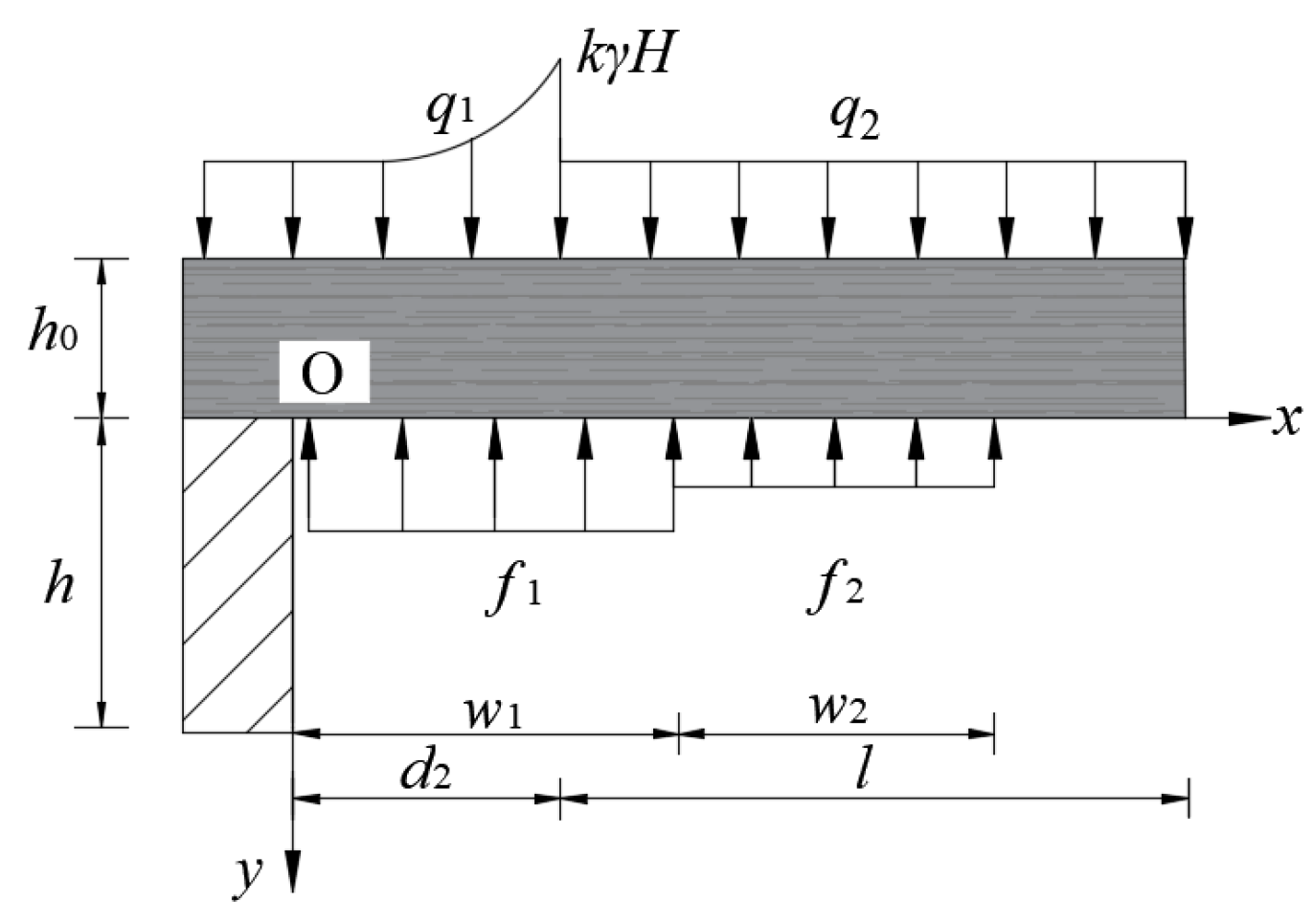
3.2.2. Main Roof Breaks above the Main Recovery Room

When the main roof beaks above the main recovery room and longwall face, the immediate roof is affected by front abutment pressure q1 as well as the pressure of key block and its overburden. The roof sag of the main recovery room is equal to the sum of deformation under the action of q1 and q2 and is written as:
u 2 = u 2 a + u 2 b
where u2a and u2b are roof sags under the action of q1 and q2, respectively.
u2a was calculated according to immediate roof deflection and u2b was determined by the principle of energy conservation in the process of roof rotary deformation. The calculation model is shown in Figure 9.
Roof sag under the action of q1 is given as:
u 2 a = w 1 2 [ ( k 1 ) γ H ( 1 e 2 f d 2 h β ) f 1 f 2 ] [ w 1 2 4 2 d 2 w 1 + 6 d 2 2 ] 8 E 0 h 0 3
In Figure 9, the immediate roof could be considered as deformation body, its upper part was the key block along with its overburden, and its lower part was supported by shield and chock hydraulic supports. According to the principle of energy conservation, the work done by roof rotary deformation was equal to the sum of the strain energy stored in the immediate roof and the work done by hydraulic supports. The energy conservation equation is expressed as:
W 1 + W 2 = W 3 + W 4 + W 5
where W1 is the work done by the key block and its overburden rotary deformation; W2 is the work done by the immediate roof rotary deformation; W3 is the strain energy stored in the immediate roof; and W4 and W5 are the work done by chock and shield hydraulic supports to the roof, respectively.
In Equation (6), the work done by the hydraulic support and the strain energy stored in protective coal pillar were all related to recovery room roof sag. Therefore, after the determination of other influential parameters in Equation (6), roof sag calculation equation was derived. The line distribution stress q2 of the key block and its overburden acting on the immediate roof was taken as unit length. When the rotation angle was α, the work done by key block is given by:
W 1 = d 2 w 1 + w 2 q 2 α x d x = 1 2 γ 1 h 1 α ( w 1 2 + 2 w 1 w 2 + w 2 2 d 2 2 )
where γ1 is the average volumetric weight of the main roof; h1 is the height of the key block and its overburden; α is the rotation angle of the key block; and l is the step of the main roof’s last weighting.
Under the action of the key block, the immediate roof deformations and the center of gravity were also changed. The deformation between the immediate roof and the key block was considered as coordinated, i.e., the rotation angle of the immediate roof was also equal to α. Therefore, according to the geometric relationship of immediate roof deformation shown in Figure 10, the displacement of the center of gravity along the vertical direction Δc is illustrated as [39]:
{ Δ c = y O C 1 y O C 2 = h 0 sin θ h 0 2 + ( d 2 + l ) 2 2 sin ( α + θ ) = h 0 h 0 2 + ( d 2 + l ) 2
The simplified expression of Equation (8) is rearranged as:
Δ c = 1 2 [ h 0 ( 1 sec α ) tan α ( d 2 + l ) ]
Therefore, the work done by immediate roof rotary deformation is expressed as:
W 2 = 1 2 γ 0 h 0 l [ h 0 ( 1 sec α ) tan α ( d 2 + l ) ]
where γ0 is the average volumetric weight of immediate roof.
The immediate roof stored energy under the action of the key block, and this part of strain energy is calculated as:
W 3 = F 2 l 2 E A = γ 1 2 h 1 2 l 2 h 0 2 E 0 ( d 2 + l )
By bearing roof deformation of the recovery room, the work done by the chock and the shield hydraulic supports are stated as:
W 4 = 0 w 1 f 1 u 2 b x w 1 / 2 d x = f 1 w 1 u 2 b
W 5 = w 1 w 1 + w 2 f 2 u 2 b x w 1 / 2 d x = f 2 w 2 u 2 b ( w 2 + 2 w 1 ) w 1
By substituting Equations (7), (10), (11), (12) and (13) into Equation (6), u2b is stated as:
u 2 b = E 0 w 1 ( d 2 + l ) { γ 1 h 1 α ( w 1 2 + 2 w 1 w 2 + w 2 2 d 2 2 ) + γ 0 h 0 l [ h 0 ( 1 sec α ) tan α ( d 2 + l ) ] } 2 γ 1 2 h 1 2 l 2 h 0 w 1 2 E 0 ( d 2 + l ) [ f 1 w 1 2 + f 2 w 2 ( w 2 + 2 w 1 ) ]
Substituting Equations (5) and (14) into Equation (4) gives the main recovery room roof sag.

3.2.3. Main Roof Breaks above Coal Pillar

When the main roof breaks above the protective coal pillar, the immediate roof is completely controlled by the key block and its overburden. Similarly, roof sag under this main roof failure form could also be calculated by the principle of energy conservation.
According to the mechanical model presented in Figure 11, the calculation equation of each parameter in Equation (6) was derived. The work done by the key block is stated as:
W 1 ¯ = d 3 w 1 + w 2 q 2 α x d x = 1 2 γ 1 h 1 α ( w 1 2 + 2 w 1 w 2 + w 2 2 d 3 2 )
The work done by the immediate roof rotary deformation is expressed as:
W 2 ¯ = 1 2 γ 0 h 0 l [ h 0 ( 1 sec α ) l tan α ]
The strain energy stored in the immediate roof is obtained as:
W 3 ¯ = γ 1 2 h 1 2 l 2 h 0 2 E 0 l
The work done by the chock and the shield hydraulic supports are calculated as:
W 4 ¯ = 0 w 1 f 1 u 3 x w 1 / 2 d x = f 1 w 1 u 3
W 5 ¯ = w 1 w 1 + w 2 f 2 u 3 x w 1 / 2 d x = f 2 w 2 u 3 ( w 2 + 2 w 1 ) w 1
When the main roof breaks above the protective coal pillar, the roof rotary deformation also compresses the outside of the coal pillar and, therefore, the strain energy stored in it, which is stated as:
W 6 ¯ = d 3 h ( γ 0 h 0 + γ 1 h 1 ) 2 2 E c
where Ec is coal elastic modulus.
Energy conservation equation is written as:
W 1 ¯ + W 2 ¯ = W 3 ¯ + W 4 ¯ + W 5 ¯ + W 6 ¯
By substituting Equations (15) to (20) into Equation (21), the calculation equation of u3 is expressed as:
u 3 = E 0 E c l w 1 { γ 1 h 1 α ( w 1 2 + 2 w 1 w 2 + w 2 2 d 3 2 ) + γ 0 h 0 l [ h 0 ( 1 sec α ) l tan α ] } E c γ 1 2 h 1 2 l 2 h 0 w 1 E 0 d 3 l h w 1 ( γ 0 h 0 + γ 1 h 1 ) 2 2 E 0 E c l [ f 1 w 1 2 + f 2 w 2 ( w 2 + 2 w 1 ) ]

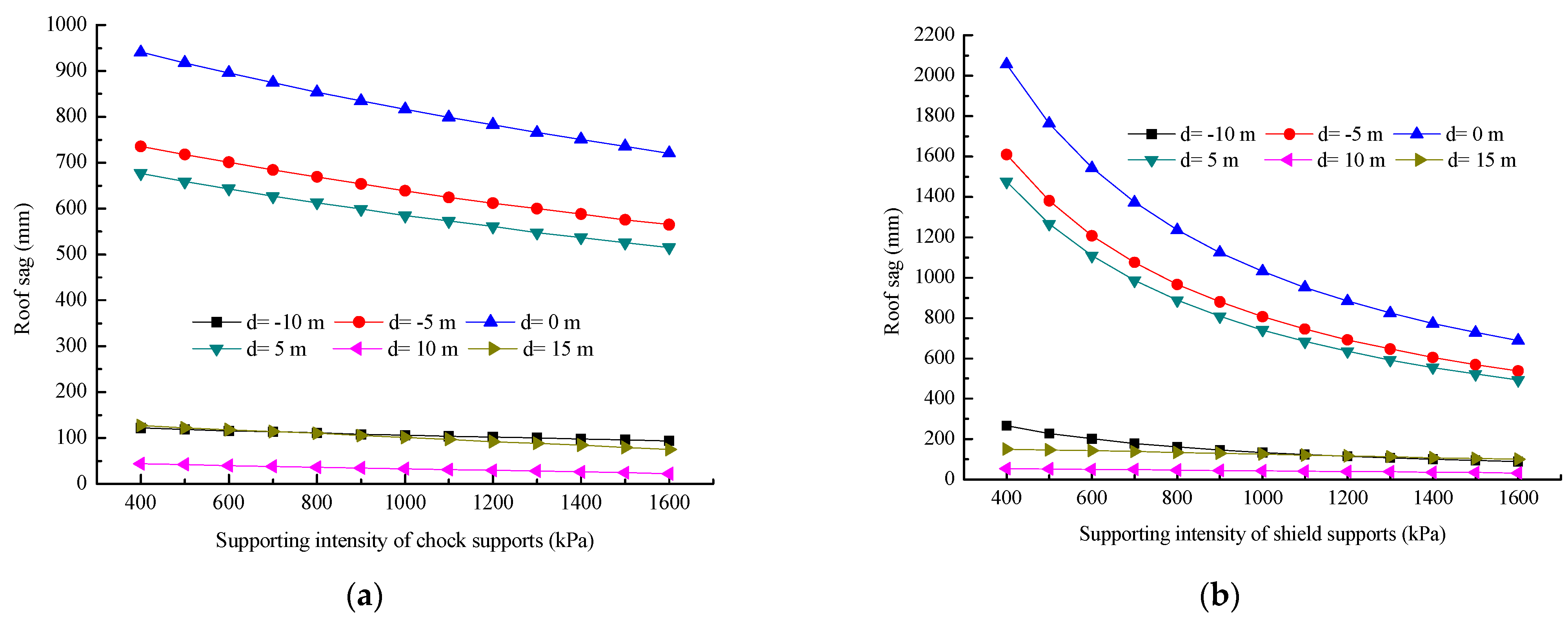
3.3. Parameter Analysis

This section can be divided into two subheadings. This should provide a concise and precise description of the experimental results, their interpretation, and experimental conclusions.
In Equations (3), (5), (14) and (22), some parameters could be directly determined by geological data and laboratory tests, while others, such as key block rotation angle, supporting intensity of shield, chock hydraulic supports and length of the key block (last weighting step) needed to be determined based on experimental and calculation data. By using the real-time mine pressure observation system of the Hongliulin Coal Mine, the last weighting steps of panels 15205 and 15206 were determined to be 19.7 and 18.3 m, respectively [31]. There were two layers of hard rock in the overburden of the 5−2 coal seam in Hongliulin Coal Mine. Based on key stratum theory, it was determined that when the main key stratum broke, h1 was 49 m [40]. The maximum rotation angle of key block is calculated as [41]:
α max = arcsin M h 0 ( k c 1 ) l = { arcsin 7 4.02 × 0.3 19.7 = 17 ( 15205   panel ) arcsin 7 4.02 × 0.3 18.3 = 19 ( 15206   panel )
where M is mining height and kc is crushing expansion which was 1.3.
Supporting intensities of shield and chock hydraulic supports needed to be calculated along with field monitoring data. The average column pressure and calculated support resistance of shield and chock hydraulic supports after the entrance of the longwall face into the main recovery room are given in Table 5. According to the data, the supporting intensities f1 and f2 could be calculated using Equations (24) and (25), respectively.
The supporting intensity of chock hydraulic supports is calculated as:
f 1 = n F c w 1 L c = { 2 × 10469 6 × 5.5 = 634 kPa   ( Panel   15205 ) 2 × 10041 6 × 5.5 = 608 kPa   ( Panel   15206 )
where Fc is the average value of chock supports resistance; Lc is the top beam length of chock support; and n is the number of chock supports for each supporting section.
The supporting intensity of shield hydraulic supports is calculated as:
f 2 = F s w 2 L s w = { 10833 6 × 1.75 = 1032 kPa   ( Panel   15205 ) 12436 6 × 1.75 = 1184 kPa   ( Panel   15206 )
where Fs is the average value of shield support resistance and Lsw is the top beam width of shield support.
The parameters required for the calculation and analysis are summarized in Table 6. The change rule of recovery room roof sag with main roof break position was obtained by taking break position d as a variable. The value of the main roof break position d is obtained by Equation (26):
d = { d 1 > w 1 + w 2     12 < d 1 20 0 d 2 w 1 + w 2     0 d 2 12 d 3 < B     10 d 3 < 0      
where B is the width of protective coal pillar.
Roof sag deviation curve and main roof break position were plotted as presented in Figure 12 by substituting the above parameters and main roof break position d as variables into Equations (3), (5), (14) and (22). It was seen from the figure that when the main roof breaks behind the shield hydraulic supports, recovery room roof sag is relatively small (no more than 80 mm). When the main roof break position moves to goaf, rock beam cantilever length was enhanced, so roof sag was gradually increased. When the main roof breaks above the main recovery room, roof sag is sharply increased and reaches its maximum when the break position is located at the edge of protective coal pillar. At this time, roof sag is close to 900 mm, which is extremely unfavorable for controlling recovery room surrounding rock. When the main roof breaks above the protective coal pillar, roof sag is gradually decreased due to the coal pillar support. In this situation, recovery room roof sag is relatively small, but because the outside of the coal pillar is affected by the main roof rotary deformation, coal pillar stress is sharply increased. Once coal stress exceeds its ultimate strength, the coal pillar is damaged by spalling, which is also unfavorable for maintaining the stability of recovery room and coal pillar.
By adjusting the parameters of panel 15206 as shown in Table 5, the effect of the supporting intensity of hydraulic supports on recovery room roof sag was analyzed, as presented in Figure 13. It was concluded that the improvement of the supporting intensity of hydraulic supports reduced recovery room roof sag. When the main roof breaks above the recovery room or the shallow part of the coal pillar, the improvement of the supporting intensity of hydraulic supports significantly controlled roof sag. When the main roof breaks above or behind the longwall face, roof sag still decreases with the increase of supporting intensity, but the decline is small. However, in engineering practice, due to the upper limit of the supporting intensity provided by hydraulic supports, it is unrealistic to blindly improve the supporting intensity of hydraulic supports. For example, the maximum supporting intensity of shield supports installed in the longwall face of the 5−2 coal seam in Hongliulin Coal Mine was 1600 kPa and the maximum supporting intensity provided by the two rows of chock supports in the recovery room was 1100 kPa. When the main roof beaks at an unfavorable position (−5 m ≤ d ≤ 5 m), even if all hydraulic supports reach their maximum supporting intensity, recovery room roof sag still ranges from 500 to 600 mm.

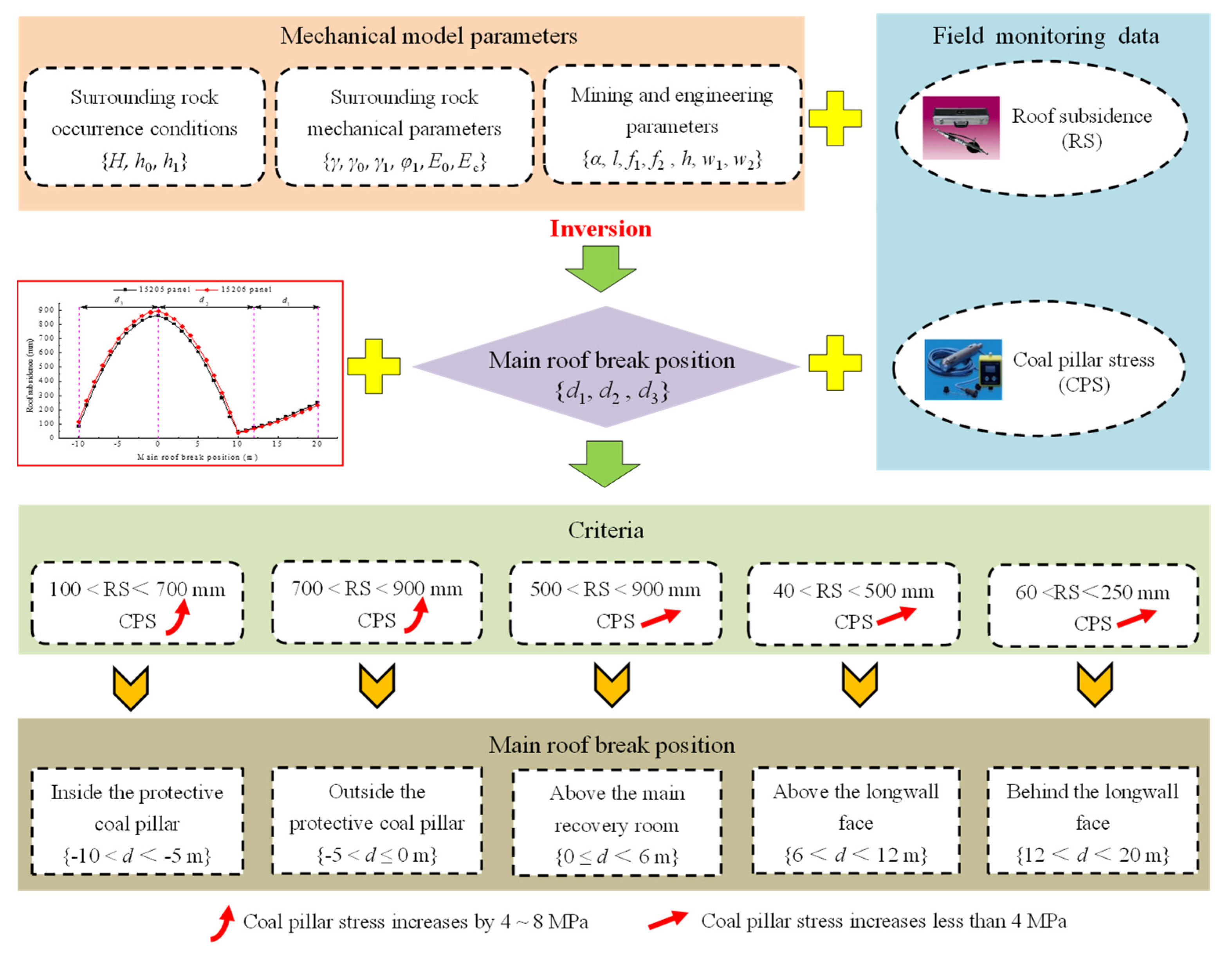
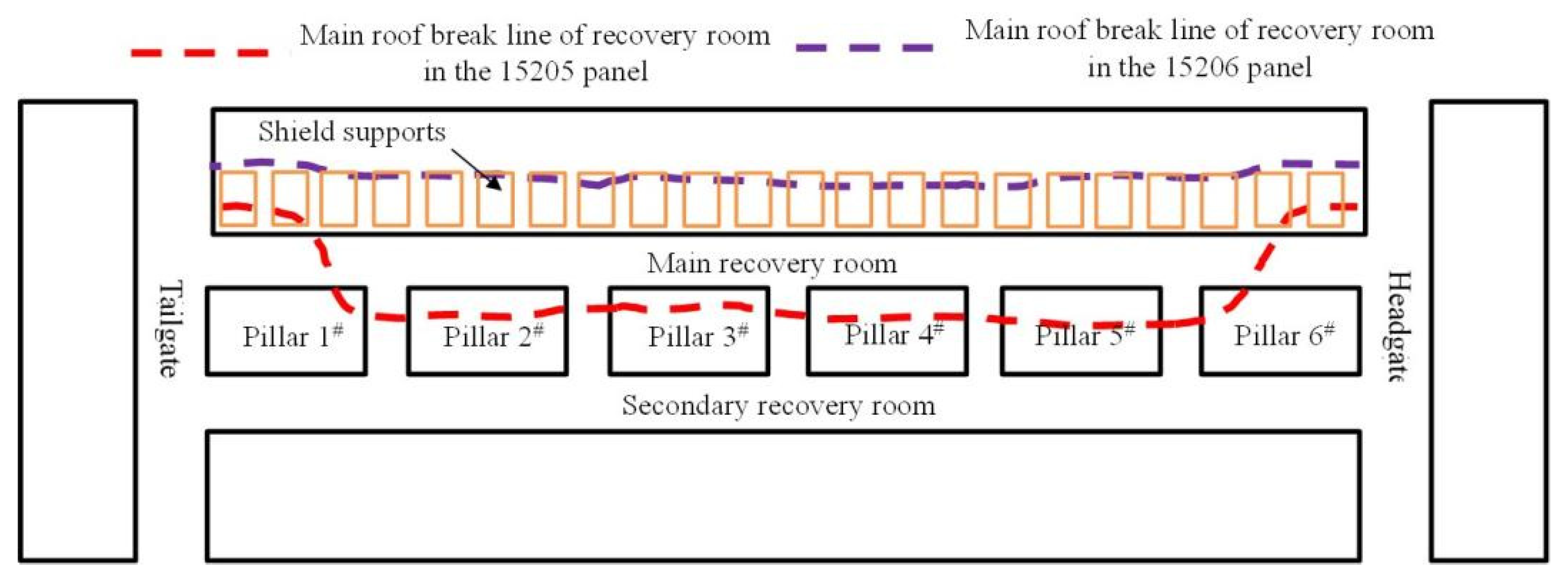
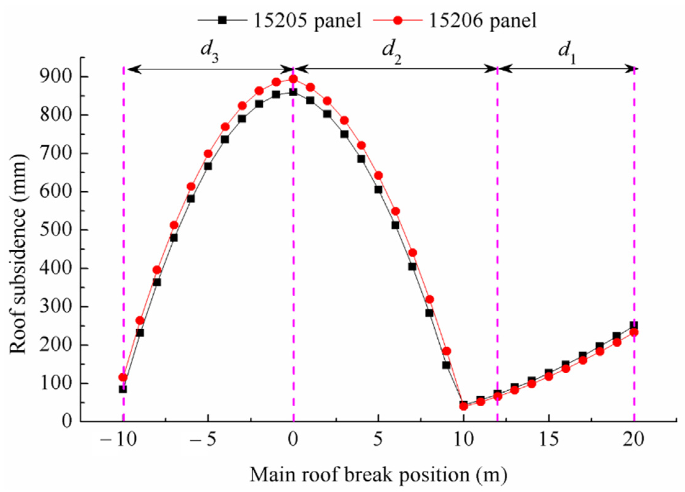
3.4. Inversion of Main Roof Break Position

Panels 15205 and 15206 were two adjacent longwall panels of the 5−2 coal seam in Hongliulin Coal Mine in Shennan mining area. The surrounding rock lithology and roof conditions of the recovery rooms in the two panels were the same with completely consistent support form and strength. However, roof sag modes in the two panels were quite different. In order to determine the deformation mechanism of the recovery room roof, the proposed mechanical model along with field monitoring data of panels 15205 and 15206 were applied to analyze roof deformation differences under similar conditions.
Based on previous analyses, after all relevant parameters were determined, the main roof break position of the recovery room could be calculated according to roof sag. However, as shown in Figure 12, two or three main roof break positions could be obtained based on the inversion calculation of roof sag. If other additional conditions were not considered, such inversion results would be meaningless. In field monitoring, roof sag and coal pillar stress are the most frequently monitored items and relevant data are also the easiest to obtain directly. Therefore, by combining field monitoring data for panels 15205 and 15206 in Hongliulin Coal Mine, we developed a method for the determination of the main roof break position for the recovery room in the 5−2 coal seam, as shown in Figure 14. The inversion discrimination of the main roof break position was divided into three steps:
Step 1: Determining overburden occurrence conditions, surrounding rock mechanical characteristic parameters and mining and engineering parameters required for theoretical models, followed by substituting the roof sag value obtained from field monitoring into the developed calculation model to obtain two or three alternative values for main roof break positions after inversion.
Step 2: Determining roof sag and coal pillar stress discrimination criteria for various main roof break positions according to coal pillar stress monitoring data and roof sag variation curve with the main roof break position.
Step 3: Filtering the inverted main roof break position data to obtain the final value to meet the conditions according to the discrimination criteria of roof sag and coal pillar stress.
Based on field monitoring data, the main roof break position of each monitoring area in the recovery room for panels 15205 and 15206 was calculated, as presented in Table 7. According to the main roof break position data calculated by inversion, the schematic diagram of the main roof break lines of panels 15205 and 15206 after the entrance of the longwall face into the main recovery room were drawn, as shown in Figure 15. Obviously, the reason for the large deformations in the surrounding rock of the recovery room in panel 15205 was that the main roof break line was above the protective coal pillar, while that in panel 15206 was relatively small because the main roof break line was above the shield support, which was closer to the 12 m calculated by Equation (27).
For verification of the rationality of the developed theoretical models, the main roof break positions calculated by periodic weighting steps were compared with inversion results. As summarized in Table 8, periodic weighting steps in the middle of recovery room in panels 15205 and 15206 were analyzed. The main roof break positions of the last weighting of panels 15205 and 15206 were estimated to be −8.2 m and 4.0 m; that is, distance from the main roof break position to the terminal line. The main roof break positions converted to distance from coal pillar edge were −2.2 m and 10 m, which were considered as the coordinate system in the model applied in this study.
From inversion results, the average values of main roof break positions in II~V monitoring areas in the middle of the recovery room in panels 15205 and 15206 were −4.2 m and 9.1 m, respectively, which accord with the main roof break position obtained by periodic weighting steps.

4. Discussion

From the above analyses, it can be seen that under similar coal mining and geological conditions, the main reason for large roof deformations in recovery rooms is the main roof break position. It can also be seen that improving support intensity could also control roof deformation to a certain extent.
In practice, hydraulic supports can rarely achieve maximum support intensity due to their own working conditions and the premise they should not replace hydraulic support selection; therefore, support intensity cannot be increased indefinitely. Hence, monitoring the working resistance of hydraulic supports and evaluating the stability of recovery room roof deformation in time are the basic conditions for safe equipment removal [42,43]. When support strength reaches the upper limit and roof sag becomes larger, additional reinforcement support measures need to be taken.
Improving support intensity is not the best approach to control recovery room roof sag. The key to control recovery room roof sag is to manually control the main roof break at a favorable position. It can be seen from the above analysis that if surrounding rock stability and equipment removal process safety in the recovery room were to be ensured, the most reasonable breaking position of the main roof last weighting is calculated as:
d 0 = w 1 + w 2
By pre-splitting the main roof to decrease the front abutment pressure at the position of d0 before the entrance of the longwall face into recovery room, the main roof would not break after the entrance of the longwall face into the recovery room and excessive roof deformation of recovery room could be avoided. At the same time, it is necessary to ensure that recovery rooms have sufficient supporting intensity to avoid the formation of adverse failure forms due to secondary breaks in the roof.
The present study was carried out under simple, shallow and hard roof conditions. Hence, the established mechanical models could be mainly applied to coal mines with similar overburden conditions. Based on the mechanical models and corresponding inversion method, more factors such as the evolution of overburden structure, elastoplasticity and meso damage failure of coal and rock mass, and dynamic load of mining should be considered in future studies.

5. Conclusions

In this study, the effect of the main roof break position on pre-driven longwall recovery room stability was investigated. Three different mechanical models were developed based on the three main roof failure modes. Also, the main roof break position of last weighting in two adjacent panels of Hongliulin Coal Mine was inversed by combining them with field monitoring data. The following conclusions were drawn:
Main roof break position is a key factor influencing recovery room roof sag. In the 5−2 coal seam, when the main roof broke near the edge of the coal pillar, the maximum roof sag of the recovery room was close to 900 mm and when it was broken behind the hydraulic supports of longwall face, it was about 40 mm, indicating a difference of more than 20 times.
Based on the established theoretical models and field monitoring data and taking the longwall face of the 5−2 coal seam in Hongliulin Coal Mine as an example, a main roof break position discrimination method was developed for recovery rooms based on the inversion of the monitoring values of roof sag and the variation amplitude of coal pillar stress. The inversion results of the main roof break position of the recovery room in panels 15205 and 15206 of Hongliulin Coal Mine were −4.2 m and 9.1 m, respectively, which were basically consistent with the −2.2 m and 10.0 m obtained from ground pressure observation results.
When the main roof breaks in an unfavorable position, it is necessary to take temporary support and reinforcement measures in the recovery room, such as adding bolts and cables and installing single hydraulic props, to control roof deformation during equipment removal. Meanwhile, it is necessary to speed up equipment removal to avoid support crushing accidents due to the continuous rotation and deformation of the key block.

Author Contributions

Conceptualization, B.W. and S.G.; methodology, B.W.; software, B.W.; validation, B.W.; formal analysis, L.M.; investigation, B.W.; resources, B.W.; data curation, B.W.; writing—original draft preparation, B.W.; writing—review and editing, L.M. and M.H.; visualization, B.W.; supervision, S.G.; project administration, B.W.; funding acquisition, B.W., L.M. and M.H. All authors have read and agreed to the published version of the manuscript.

Funding

This research was funded by the Scientific Research Program Funded by Shaanxi Provincial Education Department, grant number No.21JK0782, Natural Science Basic Research Program of Shaanxi, grant number No.2022JQ-357, National Natural Science Foundation of China, grant number No.42177158, China Postdoctoral Science Foundation, grant number No.2019M653878XB. The APC was funded by Natural Science Basic Research Program of Shaanxi, grant number No.2022JQ-357.

Institutional Review Board Statement

Not applicable.

Informed Consent Statement

Not applicable.

Data Availability Statement

Not applicable.

Conflicts of Interest

The authors declare no conflict of interest.

References

  1. Bauer, E.; Jeffery, M.; Listak, J.; Berdine, M.; Bookshar, W. Longwall recovery utilizing the open entry method and various cement-concrete supports. In Proceedings of the 7th International Conference on Ground in Mining, Morgantown, WV, USA, 3 August 1988; pp. 30–42. [Google Scholar]
  2. Bauer, E.; Listak, J.; Berdine, M. Assessment of Experimental Longwall Recovery Rooms for Increasing Productivity and Expediting Equipment Removal Operations; Report of Investigation 9248; US Department of Interior, Bureau of Mines: Washington, DC, USA, 1989; p. 20.
  3. Bauer, E.; Listak, J. Productivity and equipment removal enhancement using pre-driven longwall recovery rooms. In Proceedings of the 1989 Multinational Conference on Mine Planning and Design, Lexington, KY, USA, 1 January 1989; pp. 119–124. [Google Scholar]
  4. Smyth, J.; Stankus, J.; Wang, Y.; Guo, S.; Blankenship, J. Mining through in-panel entries and full-face recovery room without standing support at U.S. Steel Mine 50. In Proceedings of the 17th Conference on Ground Control in Mining, Morgantown, WV, USA, 4–6 August 1998; pp. 21–30. [Google Scholar]
  5. Tadolini, S.C.; Barczak, T.M.; Zhang, Y. The effect of standing support stiffness on primary and secondary bolting systems. In Proceedings of the 22nd International Conference on Ground Control Mining, Morgantown, WV, USA, 5–7 August 2003; pp. 300–307. [Google Scholar]
  6. Tadolini, S.C.; Barczak, T.M. Design parameters of roof support systems for pre-driven longwall recovery rooms. SME Annu. Meet. Exhibit. 2006, 318, 87. [Google Scholar]
  7. Tadolini, S.C.; Barczak, T.M. Rock mass behavior and support response in a longwall panel pre-driven recovery room. In Proceedings of the 6th International Symposium on Ground Support in Mining and Civil Engineering Construction, Cape Town, South Africa, 30 March–3 April 2008; pp. 167–182. [Google Scholar]
  8. Barczak, T.M.; Tadolini, S.C.; Zhang, P. Evaluation of support and ground response as longwall face advances into and widens pre-driven recovery room. In Proceedings of the 26th International Conference Ground Control Mining, Morgantown, WV, USA, 31 July–2 August 2007; pp. 160–172. [Google Scholar]
  9. Barczak, T.M.; Tadolini, S.C. Pumpable roof supports: An evolution in longwall roof support technology. Trans. Soc. Min. Met. Explor. 2008, 324, 19–31. [Google Scholar]
  10. Barczak, T.M.; Esterhuizen, G.S.; Ellenberger, J.L. A first step in developing standing roof support design criteria based on ground reaction data for Pittsburgh seam longwall tailgate support. In Proceedings of the 27th International Conference on Ground Control Mining, Morgantown, WV, USA, 29–31 July 2008; pp. 349–359. [Google Scholar]
  11. Thomas, R. Recent developments in pre-driven recovery road design. In Proceedings of the 27th International Conference on Ground Control in Mining, Morgantown, WV, USA, 29–31 July 2008; pp. 197–205. [Google Scholar]
  12. Zorkov, D.; Renev, A.; Filimonov, K.; Zainulin, R. The roof support load analysis for pre-driven recovery room parameters design. In Proceedings of the 5th International Innovative Mining Symposium, Kemerovo, Russia, 19–21 October 2020. [Google Scholar]
  13. Shu, C.X.; Jiang, F.X.; Han, Y.W.; Li, D. Long-distance multi-crosscut rapid-retracement technique in deep heavy fully mechanized face. J. Min. Safe Eng. 2018, 35, 473–480. [Google Scholar]
  14. Pan, W.D.; Li, X.Y.; Li, Y.W.; Li, X.B.; Qiao, Q.; Gong, H. A supporting design method when longwall face strides across and passes through a roadway. Adv. Mater. Sci. Eng. 2020, 2020, 8891427. [Google Scholar] [CrossRef]
  15. Listak, J.; Bauer, E. Front abutment effects on supplemental supports in pre-driven longwall equipment recovery rooms. In Proceedings of the 30th U.S. Symposium on Rock Mechanics, Morgantown, WV, USA, 19–22 June 1989. [Google Scholar]
  16. Wynne, T.; John, S.; Guo, S.; Peng, S.S. Design, monitoring and evaluation of a pre-driven longwall recovery room. In Proceedings of the 12th International Conference on Ground Control in Mining, Morgantown, WV, USA, 3–5 August 1993; pp. 205–216. [Google Scholar]
  17. Oyler, D.C.; Frith, R.C.; Dolinar, D.R.; Mark, C. International experience with longwall mining into pre-driven rooms. In Proceedings of the 17th International Conference on Ground in Mining, Morgantown, WV, USA, 4–6 August 1998; pp. 44–53. [Google Scholar]
  18. Oyler, D.C.; Mark, C.; Dolinar, D.R.; Frith, R.C. A study of ground control effects of mining longwall faces into pre-driven longwall recovery room. Geotech. Geol. Eng. 2001, 19, 137–168. [Google Scholar] [CrossRef]
  19. Tadolini, S.C.; Zhang, Y.; Peng, S.S. Pre-driven experimental longwall recovery room under weak roof conditions design, implementation, and evaluation. In Proceedings of the 21st International Conference on Ground Control Mining, Morgantown, WV, USA, 6–8 August 2002; pp. 1–10. [Google Scholar]
  20. Wu, Z.G.; Li, W.Z. Strata response principle and stress distribution characters of pre-driven recovery room. In Proceedings of the 30th Annual International Pittsburgh Coal Conference, Beijing, China, 15–18 September 2013; pp. 4124–4130. [Google Scholar]
  21. Wu, Z.G.; Li, W.Z. Surrounding rock convergence rule along the working face tendency of recovery room. In Proceedings of the 3rd International Conference on Energy and Environmental Protection, Xi’an, China, 26–28 April 2014; pp. 962–965. [Google Scholar]
  22. Zhu, C.; Yuan, Y.; Chen, Z.; Meng, C.; Wang, S. Study of the stability control of rock surrounding longwall recovery roadways in shallow seams. Shock Vib. 2020, 2020, 2962819. [Google Scholar] [CrossRef]
  23. Kang, H.P.; Lv, H.W.; Zhang, X.; Gao, F.Q.; Wu, Z.; Wang, Z. Evaluation of the ground response of a pre-driven longwall recovery room supported by concrete cribs. Rock Mech. Rock Eng. 2016, 49, 1025–1040. [Google Scholar] [CrossRef]
  24. Wang, B.; Dang, F.; Chao, W.; Miao, Y.; Li, J.; Chen, F. Surrounding rock deformation and stress evolution in pre-driven longwall recovery rooms at the end of mining stage. Int. J. Coal Sci. Technol. 2019, 6, 536–546. [Google Scholar] [CrossRef] [Green Version]
  25. Feng, G.; Li, S.; Wang, P.; Guo, J.; Qian, R.; Sun, Q.; Hao, C.; Wen, X.; Liu, J. Study on floor mechanical failure characteristics and stress evolution in double predriven recovery rooms. Math. Probl. Eng. 2020, 2020, 9391309. [Google Scholar] [CrossRef] [Green Version]
  26. Gu, S.C.; Huang, R.B.; Li, J.H.; Su, P.L. Stability analysis of un-mined coal pillars during the pressure adjustment prior to working face transfixion. J. Min. Safe Eng. 2017, 34, 151–156. [Google Scholar]
  27. Wang, F.T.; Shao, D.L.; Niu, T.C.; Dou, J.F. Progressive loading characteristics and accumulated damage mechanisms of shallow-buried coal pillars in withdrawal roadways with high-strength mining effect. Chin. J. Rock Mech. Eng. 2022, 41, 1148–1159. [Google Scholar]
  28. He, Y.J.; Song, Y.X.; Shi, Z.S.; Li, J.Q.; Chen, K.; Li, Z. Study on failure mechanism of withdrawal channel’s surrounding rock during last mining period. China Safe Sci. J. 2022, 32, 158–166. [Google Scholar]
  29. Zhang, Y.; Li, H.; Zhang, X.; Zhao, Y.; Zhao, R. Study on impact mechanism of double withdrawal channels in fully mechanized mining face based on overburden theory. Chin. J. Undergr. Space Eng. 2022, 18, 305–312. [Google Scholar]
  30. Lv, H.W. The mechanism of stability of pre-driven rooms and the practical techniques. J. China Coal Soc. 2014, 39 (Suppl. S1), 50–56. [Google Scholar]
  31. Wang, B.N.; Dang, F.N.; Gu, S.C.; Huang, R.B.; Miao, Y.; Chao, Y. Method for determining the width of protective coal pillar in the pre-driven longwall recovery room considering main roof failure form. Int. J. Rock Mech. Min. Sci. 2020, 130, 104340. [Google Scholar] [CrossRef]
  32. Wang, S.S.; Wang, Z.Q.; Huang, X.; Su, Z.H. Calculation of direct roof subsidence of retracement channel and analysis of its influencing factors. J. Min. Sci. Technol. 2021, 6, 409–417. [Google Scholar]
  33. Chen, Y.G.; Lu, S.L. Strata Control around Coal Mine Roadways in China; China university of mining and technology press: Xuzhou, China, 1994. [Google Scholar]
  34. Qian, M.G.; Shi, P.W.; Xu, J.L. Mine Pressure and Strata Control; China university of mining and technology press: Xuzhou, China, 2010. [Google Scholar]
  35. Wang, X.Z.; Ju, J.F.; Xu, J.L. Theory and applicable of yield mining at ending stage of fully-mechanized face in shallow seam at Shendong mine area. J. Min. Safe Eng. 2012, 29, 151–156. [Google Scholar]
  36. Liu, C.; Yang, Z.; Gong, P.; Wang, K.; Zhang, X.; Zhang, J.; Li, Y. Accident analysis in relation to main roof structure when longwall face advances toward a roadway: A case study. Adv. Civ. Eng. 2018, 2018, 3810315. [Google Scholar] [CrossRef] [Green Version]
  37. Chen, Z.S.; Yuan, Y.; Zhu, C.; Wang, W.M. Stability mechanism and control factors on equipment removal area under “goaf-roof-coal” structure. Adv. Civ. Eng. 2021, 2021, 6628272. [Google Scholar] [CrossRef]
  38. Chen, Y.G.; Qian, M.G. Strata Control around Coal Face in China; China university of mining and technology press: Xuzhou, China, 1994. [Google Scholar]
  39. Chen, Y. Study on Stability Mechanism of Rock Mass Structure Movement and Its Control in Gob-Side Entry Retaining. Doctor Thesis, China University of Mining and Technology, Xuzhou, China, 2012. [Google Scholar]
  40. Xu, J.L.; Qian, M.G. Method to distinguish key strata in overburden. J. China Univ. Min. Tech. 2000, 29, 463–467. [Google Scholar]
  41. Fu, Y.P.; Song, X.M.; Xing, P.W.; Yan, G.C. Stability analysis on main roof key block in large mining height workface. J. China Coal Soc. 2014, 34, 1027–1031. [Google Scholar]
  42. Herezy, L.; Janik, D.; Skrzypkowski, K. Powered Roof Support-Rock Strata Interactions on the Example of an Automated Coal Plough System. Studia Geo. Mech. 2018, 40, 46–55. [Google Scholar] [CrossRef] [Green Version]
  43. Skrzypkowski, K.; Korzeniowski, W.; Duc, T.N. Choice of powered roof support FAZOS-15/31-POz for Vang Danh hard coal mine. Inz. Miner.-J Pol. Min. Eng. Soc. 2019, 2, 174–181. [Google Scholar] [CrossRef]
Figure 1. Large deformation of roof and hydraulic support crushing accident of a recovery room in Shennan mining area: (a) less than 100 mm stroke of hydraulic support column; and (b) completely crushed hydraulic support.
Sustainability 14 09093 g001
Figure 2. Plan view of support design for the main recovery room.
Sustainability 14 09093 g002
Figure 3. Layout of roof deformation and coal pillar stress monitoring areas in the main recovery room.
Sustainability 14 09093 g003
Figure 4. Roof deformation and coal pillar stress monitoring results of recovery room: (a) distribution and comparison of the roof sag of the main recovery rooms in panels 15205 and 15206; (b) field monitoring results of protective coal pillar stress in panel 15205; (c) field monitoring results of protective coal pillar stress in panel 15206.
Sustainability 14 09093 g004
Figure 5. Variation curve of roof subsidence with mining progress: (a) panel 15205; (b) panel 15206.
Sustainability 14 09093 g005
Figure 6. Spalling failure of protective coal pillar in the main recovery room: (a) panel 15205; (b) panel 15206.
Sustainability 14 09093 g006
Figure 7. Main roof failure forms following the entrance of longwall face into main recovery room: (a) main roof breaking behind longwall face; (b) main roof breaking above main recovery room and longwall face; and (c) main roof breaking above protective coal pillar.
Sustainability 14 09093 g007
Figure 8. Mechanical model for roof sag when the main roof breaks behind shield hydraulic supports.
Sustainability 14 09093 g008
Figure 9. Mechanical model for roof sag when the main roof breaks above the main recovery room and longwall face.
Sustainability 14 09093 g009
Figure 10. Geometric relationship of the rotary motion of immediate roof.
Sustainability 14 09093 g010
Figure 11. Mechanical model for roof sag when the main roof breaks above the main recovery room.
Sustainability 14 09093 g011
Figure 12. Influence of main roof break position on the roof sag of panels 15205 and 15206.
Sustainability 14 09093 g012
Figure 13. Influence of the supporting intensity of hydraulic supports on the roof sag of recovery room: (a) chock supports; (b) shield supports.
Sustainability 14 09093 g013
Figure 14. Inversion discrimination method of main roof break position in recovery room: taking the 5−2 coal seam as an example.
Sustainability 14 09093 g014
Figure 15. Distribution diagram of main roof break line of recovery room in panels 15205 and 15206.
Sustainability 14 09093 g015
Table 1. Lithology and roof condition of 5−2 coal seam.
Coal Seam NumberCoal Seam Average Thickness (m)Immediate RoofMain RoofAverage Depth (m)
LithologyAverage Thickness (m)LithologyAverage Thickness (m)
5−27.23Sandstone7.50Medium sandstone19.2723–206
Table 2. Pattern of supports in the main recovery room of panels 15205 and 15206.
Longwall PanelArrangementSupport Pattern (Main Recovery Room)
RoofCoal Pillar RibMining Rib
15205Pre-driven double recovery roomSteel bolts, cables, and hydraulic supportsSteel boltsFRP bolts
15206
Table 3. Support parameters and mining conditions of panels 15205 and 15206.
Longwall PanelLongwall FaceMain Recovery Room
Mining Height (m)Shield Supports Resistance(kN)Height (m)Width (m)Chock Supports Resistance (kN)Coal Pillar Width (m)
152056.717,0004.56.018,00020
15206
Table 4. Classification of surrounding rock stability of mining roadway.
Stability Category of Roadway Surrounding RockStability of Roadway Surrounding RockRoof Sag of Mining Roadway (mm)
AverageRange
Extremely stable3010~50
IIStable7550~100
IIIModerately stable250100~400
IVUnstable500400~600
VExtremely unstable1200600~1800
Table 5. Pressure calculation results of hydraulic supports in panels 15205 and 15206 after the entrance of the longwall face into the main recovery room.
Longwall PanelAverage Column Pressure of Hydraulic Supports (MPa)Average Value of Support Resistance (kN)
Chock SupportsShield SupportsChock SupportsShield Supports
1520523.0926.6210,46910,833
1520622.1530.5610,04112,436
Table 6. Statistics of occurrence conditions, surrounding rock mechanical parameters and engineering factors of the 5−2 coal seam.
Longwall PanelSurrounding Rock Occurrence ConditionsSurrounding Rock Mechanical ParametersMining and Engineering Parameters
H
(m)
h0
(m)
h1
(m)
γ
(kN/m3)
γ0
(kN/m3)
γ1
(kN/m3)
φ1
(°)
E0
(GPa)
Ec
(GPa)
α
(°)
l
(m)
f1
(kPa)
f2
(kPa)
h
(m)
w1
(m)
w2
(m)
15205 1554.024922.223.523.9381.91.11719.763410324.56.06.0
152061471918.36081184
Table 7. Calculation of main roof break position in each monitoring area.
Number of Monitoring Area15205 Panel15206 Panel
Average Roof Sag (mm)Main Roof Break Position (m)Average Roof Sag (mm)Main Roof Break Position (m)
I2408.3 (19.6, −8.9)3810
II760−3.6 (2.8)1429.3 (16.2, −9.8)
III816−2.4 (1.6)1779.1 (17.8, −9.6)
IV724−4.2 (3.4)1938.9 (18.4, −9.5)
V521−6.6 (5.8)1539.2 (16.7, −9.8)
VI1848.7 (17.5, −9.3)3910
Note: the italicized numbers in brackets represent the data removed after filtering.
Table 8. Periodic weighting positions and steps of each panel.
Longwall Panel1520515206
Number of
Periodic Weighting
Position
(m)
Step
(m)
Position
(m)
Step
(m)
1208205
2189.518.5186.518.5
3169.520163.523
415019.514815.5
513119136.511.5
61102111917.5
791.518.510316
87219.58320
9531960.522.5
10341942.518
1111.522.52220.5
12−8.219.7418
Main roof break position of
last weighting (m)
−2.210
Publisher’s Note: MDPI stays neutral with regard to jurisdictional claims in published maps and institutional affiliations.

