Article

Experimental Investigation of an Adaptive Fuzzy-Neural Fast Terminal Synergetic Controller for Buck DC/DC Converters

by
Badreddine Babes
1,
Noureddine Hamouda
1,
Fahad Albalawi
2,
Oualid Aissa
3,
Sherif S. M. Ghoneim
2,* and
Saad A. Mohamed Abdelwahab
4,5
1
Research Center in Industrial Technologies (CRTI), P.O. Box 64, Cheraga 16014, Algeria
2
Department of Electrical Engineering, College of Engineering, Taif University, P.O. Box 11099, Taif 21944, Saudi Arabia
3
LPMRN Laboratory, Faculty of Sciences and Technology, University of Bordj Bou Arreridj, El Anseur 34000, Algeria
4
Electrical Department, Faculty of Technology and Education, Suez University, Suez 43533, Egypt
5
Department of Computers & Systems Engineering, High Institute of Electronic Engineering, Ministry of Higher Education, Bilbis-Sharqiya 44621, Egypt
*
Author to whom correspondence should be addressed.
Sustainability 2022, 14(13), 7967; https://doi.org/10.3390/su14137967
Submission received: 2 June 2022 / Revised: 26 June 2022 / Accepted: 26 June 2022 / Published: 29 June 2022

Abstract

:
This study proposes a way of designing a reliable voltage controller for buck DC/DC converter in which the terminal attractor approach is combined with an enhanced reaching law-based Fast Terminal Synergetic Controller (FTSC). The proposed scheme will overcome the chattering phenomena constraint of existing Sliding Mode Controllers (SMCs) and the issue related to the indefinite time convergence of traditional Synergetic Controllers (SCs). In this approach, the FTSC algorithm will ensure the proper tracking of the voltage while the enhanced reaching law will guarantee finite-time convergence. A Fuzzy Neural Network (FNN) structure is exploited here to approximate the unknown converter nonlinear dynamics due to changes in the input voltage and loads. The Fuzzy Neural Network (FNN) weights are adjusted according to the adaptive law in real-time to respond to changes in system uncertainties, enhancing the increasing the system’s robustness. The applicability of the proposed controller, i.e., the Adaptive Fuzzy-Neural Fast Terminal Synergetic Controller (AFN-FTSC), is evaluated through comprehensive analyses in real-time platforms, along with rigorous comparative studies with an existing FTSC. A dSPACE ds1103 platform is used for the implementation of the proposed scheme. All results confirm fast reference tracking capability with low overshoots and robustness against disturbances while comparing with the FTSC.

1. Introduction

1.1. Motivation

The buck DC/DC converter is a common choice in many applications in electric power supply systems, including DC motor drives, DC microgrids, automobiles, sailboats, airplanes, solar systems, and many more. Its mathematical model is a nonlinear and time-varying system based on state-space equations. These equations must be treated around the steady-operating point with a small-signal linearization approach before being studied with PID controllers. When a severe disturbance causes a substantial divergence from the typical operating point, it is difficult for a standard buck DC/DC converter to achieve perfect stability [1]. In light of this, adjusting the output voltage of the buck DC/DC converter is a challenging task. Realizing a robust control strategy for buck DC/DC converter is a critical challenge for better understanding the design aspect of the regulator and stability problem [2]. Furthermore, it can aid to enhance transient and steady-state conditions under a variety of disturbances. To overcome some of the previously mentioned challenges, this work suggests an AFN-FTSC algorithm for the output voltage control without complete converter model knowledge. FNN model, and universal approximator, are utilized in an adaptive scheme to approximate the converter nonlinear dynamics, while the FTSC algorithm is utilized to guarantee robustness through an easy-to-implement chatter-free continuous control law [1].

1.2. Related Work

To provide better performance for buck DC/DC converters, numerous intelligent and nonlinear control techniques have been introduced over the last decade. In paper [3], the performance of the buck DC/DC converter is evaluated by variable structure controllers in which the output voltage is tracked and regulated in a good way; however, the robustness of these controlling techniques is not acceptable against noise, chattering, parametric variations, and disturbances, which makes them practically unsuitable [4]. Otherwise, because of the switching properties of buck DC/DC converter, digital discrete control methods like repetitive [5], dead beat [6], and internal model [7] controllers have been recommended for buck DC/DC converter. The main advantage of a repetitive controller is low output distortion; however, it has some limitations such as poor tracking, large memory capacity, poor performance, and slow dynamics. Nevertheless, the internal model and dead beat controller can provide output voltage tracking without ringing and overshoot; however, the complex controlling structure of the internal model and dead beat controllers have influenced their efficiency.
In paper [8], a feedback linearization scheme is utilized for the buck DC/DC converter to control the output voltage, and model predictive controllers are presented in [9], and [10] to achieve the same goal. Both feedback linearizing and model predictive controllers provide similar advantages such as reliable reference tracking, constant switching frequency, and fast dynamic response; these controllers do not perform well under the variation in parameters due to their requirements of using precise parametric information during the implementation, and it is quite impossible to precisely know the parameters of the system as many of these vary with operating scenarios. An adaptive model predictive controller is introduced in [11] by capturing linear parameter variations so that parameter sensitivity can be alleviated. However, the inclusion of such parameter variations complicates the process of solving the optimization problem for the model predictive scheme. The Synergetic Controller (SC) is another useful alternative way of controlling the buck DC/DC converters, which can also ensure the robustness against parameter variations and disturbances by using a generalized state-space averaged representation of the system. The SC inherently alleviates the effects of external disturbances, nonlinearities, and uncertainties [12]. For all these features, SCs are extensively used for power electronic applications, including the buck DC/DC converter [13]. The standard SC scheme uses the linear manifold as a macro-variable as presented in [14] to guarantee the asymptotic convergence of the error. However, such a macro-variable makes the system static during the fluctuations in the load voltage, and therefore, it results in poor voltage tracking during transients in the system [14]. Although the gain parameters for such traditional SCs can be adjusted to ensure better transients, there are no guarantees that the system variable reaches their equilibriums in a finite time. These problems can be overcome by using SC schemes such as the Non-Singular Terminal Synergetic Control and FTSC that ensure finite-time convergence, as presented in [15,16]. However, these methods slow down the dynamic response by reducing the likelihood of overshoots during load changes and other transients during the starting. The dynamic response for regulating the output voltage during transients is accelerated in [13] using an adaptive FTSC based on dual Radial Basis Function Neural Networks (RBFNN-FTSC) control. Moreover, all adaptive SC approaches in the existing literature on the buck DC/DC converters use classical adaptive law, for which there is a possibility to induce the chattering causing ripples at the output voltage during their practical or real-time implementations. In recent years, FNN models are a hybrid approach that combines the learning ability of a neural network with the noise-handling capabilities of fuzzy logic (FL). They are commonly used in adaptive control to cope with uncertainties and attain improved performance standards. [17,18]. Although the FNNs have extensively been utilized in different adaptive controls, the applications of FNNs for uncertain nonlinear systems are relatively new and only a few applications can be seen throughout the literature. Based on the author’s knowledge, the applications of AFN-FTSC for DC/DC buck converters have not been investigated until now. Motivated by the existing literature, the considered controller design process in the current research investigates a new digital controller based on AFN-FTSC for buck DC/DC converters without the previously mentioned problems.

1.3. Novelty and Principal Contributions

The main innovative features of the proposed scheme are:
(i)
It is the first time a FNN model has been developed based on FTSC for DC/DC buck converters;
(ii)
Unlike closely related work, the proposed AFN-FTSC is created by incorporating the macro-variable to tackle the chattering effects, decrease the time of convergence, simplify the expression of the controller, and ensure a fast transient reaction, low steady-state error, and high output voltage tracking accuracy;
(iii)
A Lyapunov stability theorem is rigorously used to demonstrate the overall stability of the system and to obtain the updated rules for the FNN weights.
(iv)
The removal of demand for an accurate model by using a FNN approximator to estimate an unknown buck DC/DC converter functions;
(v)
Experiments are carried out to demonstrate efficiency while assisting to achieve desired goals under a variety of operating situations.
(vi)
It simultaneously ensures the higher output voltage tracking accuracy, swift transient responses, and less impact by disturbances and uncertainties due to the use of adaptive time-varying reaching law.

1.4. Organization of the Paper

The remaining part of the study is structured as follows. The basic requirements for SC and FNNs are briefly discussed in Section 2. The representation of the DC/DC buck converter is introduced in Section 3. The steps for designing the AFN-FTSC algorithm are presented in Section 4, including the stability and reachability analysis. Afterward, results from experimental tests are presented in Section 5 to illustrate the efficacy and practicality of the designed AFN-FTSC algorithm. Finally, the conclusions and some recommendations for further investigation are given in Section 6.

2. Preliminaries

2.1. Principle of Synergetic Control (sc)

SC algorithm is effectively a nonlinear control strategy based on the principle of directional self-organization theory and the usage of the standard nonlinear characters of dynamic systems. The fundamental idea of the SC algorithm is as follows:
  • Invariant manifold is created in the state-space of a controllable system. On this attractor, we guarantee the organization of the preferred static and dynamic behavior of the controllable system. The design of the attractor is the indication of a directed self-organization principle.
  • The most important premise in the theory of SC is the principle of compression–decompression of the phase flow of the controllable objects.
  • The designer’s necessities are given in the form of an affine system that describes the preferred operating modes of the controlled systems.
Consider the nonlinear affine dynamical system of degree n given by:
x ˙ = d x d t = f ( x , u , t )  
where xRn, uRm, indicating the state-variable and control-variables, respectively. The f(.) indicates a continuous nonlinear function. The SC design structure starts with defining a macro-variable φ as a function of the state variables [19]:
φ = φ ( x , t )  
The primary goal of the SC is to force the system to function on a pre-determined manifold φ = 0. Develop a SC that forces system variables to approach the desired manifold exponentially, with an evolution constraint that may be expressed as:
κ φ ˙ + φ = 0 , κ > 0  
where φ is the derivative of the aggregated macro-variables, and κ is a positive integer that enables the designer to choose the rate of convergence to the selected attractor. The solution of (3) gives the following function for φ(t):
φ ( t ) = φ 0 e t / κ  
It affirms that φ(t)→0 at t→∞, which implies that φ(t) is attracted to φ = 0 from any starting location φ0 (Figure 1). Since the time constant κ > 0, the macro-variable φ will decay exponentially with a speed determined by κ. As long as the system is stable, the smaller value of κ is faster than the macro-variable decays. When φ approaches zero, the system converges to the manifold and then functions on the manifold without interruption.
Considering the differentiation chain provided by:
φ ˙ = d φ ( x , t ) d t = φ ( x , t ) x . d x ( t ) d t  
When (1) and (3) are substituted into (5), we get (6):
κ d φ ( x , t ) x f ( x , u , t ) + φ ( x , t ) = 0  
Resolving (6) for the control vector u gives the SC law as:
u = g ( x , φ ( x , t ) , κ , t )  
The SC law (7) permits state trajectories to follow certain paths (3). Proper selection of the macro-variable (2) and judicious manifolds ensure the necessary performance and stability [20]. It is worth noting that SC law (7) can be rewritten as a solution to a Kolesnikov’s problem (8). Choose the performance index as follows [21]:
J   = 0 Γ ( φ ˙ , φ ) d t = 0 ( k = 1 m κ k 2 φ ˙ k 2 + φ k 2 ) d t  
A Lyapunov function candidate as in (9) can be used to determine the system’s asymptotic stability:
V ( t ) = 0.5 φ ( x , t ) 2  
The following inequality is fulfilled when the condition of κ > 0 is met:
V ˙ ( t ) = φ ( x , t ) φ ˙ ( x , t ) = 1 κ φ ( x , t ) 2 < 0  
Figure 2 illustrates the system’s phase profile as well as the SC law’s stability features, and also shows the convergence to the manifold. The steady-state operating point is the origin if the error is equal to 0. A straight line through the origin with a slope (−1/κ) is represented by Equation (3). The operational point of the system converges to the straight line (the control manifold) and then moves along it to the origin.
The schematic representation, illustrating the suggested controller’s computations, is shown in Figure 3.

2.2. Principle of Fnn Approximator

It is known that FNNs are universal estimators and have exceptional functions in controller design and identification. The properties of the FNN, such as accelerating the learning process and finer granularity to make decisions [22], make it appropriate for real-time control systems and are capable of enhancing the control precision, stability, and flexibility of the system. The FNN is an implementation of fuzzy logic (FL) with trainable parameters similar to an ANN, which comprises four layers of neurons. They are the input layer-1; the membership layer-2; the rule layer-3; and the output layer-4, respectively, all of which are depicted in Figure 4. The key characteristic of the FNN is its ability to describe the human-like reasoning and successfully cope with experience by using conditional fuzzy IF-THEN rules to build a mapping from an input vector x to an output vector y, which may be expressed as:
R l : I f x 1 i s A 1 l ( x 1 ) , x 2 i s A 2 l ( x 2 ) , , x n i s A n l ( x n ) T h e n y 1 i s B 1 l , y 2 i s B 2 l , , y m i s B m l  
where L = 1, 2, …, with L representing the overall number of IF-THEN rules, x = [x1, x2,…, xn]T and y = [y1, y2,…, ym]T characterize the input and output parameter vectors of FNN. A 1 l   a n d   B 1 l are the linguistic variables of the fuzzy sets, expressed by their membership function vectors μAil(xi) and μBil(y), respectively.
Based on the singleton fuzzifier, product inference model, and center-average defuzzifier, the final output O(x) can be obtained by the FNN estimator as in [22]:
o ( x ) = l = 1 L ( i = 1 n μ A i l ( x i ) ) y - j l l = 1 L ( i = 1 n μ A i l ( x i ) )  
where y - j l is the point in at which μ B j l ( y j ) attains its optimal value ( μ B j l ( y j ) = 1 considering).
If y - j l are selected as the free parameter vector, the FNN approximator (12) becomes an adaptive FNN. Then, it can be expressed in compact form as:
y j ( x ) = l = 1 L y - j l = w T ϕ ( x )  
where w = [ y ¯ j 1 , y ¯ j 2 , , y ¯ j L ] T R L is called the regulating parameter vector, and ϕ ( x ) = [ ϕ 1 ( x ) , ϕ 2 ( x ) , , ϕ L ( x ) ] T R L is the vector of fuzzy primary function, or the fuzzy basis function (FBFs) is obtained by (14):
ϕ j ( x ) = i = 1 n μ A i l ( x i ) j = 1 L ( i = 1 n μ A i l ( x i ) )  
Remark 1.
It ought to be indicated that the complexity of the designed AFN-FTSC algorithm is dependent on the complexity of FNN approximator. Suppose that the number of FNN inputs is n, and the number of fuzzy variables is m.
The complexity of the AFN-FTSC is composed of the fuzzy layer (layer 2) and fuzzy inference layer (layer 3). The complexity of the fuzzy layer is O(n × m), and the complexity for the fuzzy inference production layer is O(m2). The total complexity of the AFN-FTSC algorithm is O(n × m) + O(m2).

3. Mathematical Model of Buck DC/DC Converter

Figure 5 shows a buck DC/DC converter that connects an input DC voltage Vin with a DC load Ro having its output voltage as Vo. The buck DC/DC converter encompasses an adjustable switch Q, diode D, an inductor L with iL as the current flowing through it, a capacitor C with iC as the current flowing through it, and a load resistor R0 where iR is the load current.
Due to the nonlinear behavior of the diode and MOSFET/IGBT switch, the buck DC/DC converter has a nonlinear structure. Moreover, there are two charging elements an inductor and capacitor for which the mathematical model for the system will be a second-order one.
The dynamic of the system in Figure 5 will be represented by the change in the voltage Vo across Ro, which is also the voltage across C. Similarly, iL will change as it flows through L. Since the switch will be in two modes, ON and OFF, there will be two stages.
When the switch is turned ON in the first stage, equations representing the state-space model can be stated in the following way [23]:
{ d i L d t = 1 L V o + V i n L u d V o d t = 1 C i L 1 R C V o  
In the second stage, the switch is turned OFF. In this case, the diode D is in forwarding bias and the circuit is then equivalent to a parallel RLC circuit.
For this circuit, the equation representing the state-space model can be written as follows:
{ d i L d t = 1 L V o + V i n L u d V o d t = 1 C i L 1 R C V o  
At this stage, the complete dynamical average model can be obtained by combining (15) and (16) as:
{ d i L d t = 1 L V o + V i n L u d V o d t = 1 C i L 1 R C V o  
Where u is the control input, which is recognized as 0 when the switch Q is turned OFF and 1 when it is turned ON, considering the capacitor voltage and its derivative as system state variables x1 and x2, respectively. Equation (18) represents the final model of the buck DC/DC converter, which is utilized to design the proposed composite controller as discussed in the section below:
{ x ˙ 1 = x 2 x ˙ 2 = x 1 L C x 2 R C + V i n L C u  

4. Proposed Robust AFN-FTSC Design

This section focuses on determining the switching control input u using the proposed AFN-FTSC law for system (18) as a function of state coordinates (e1, e2), which gives the desired value of converter output voltage Vo-ref without the prior modeling information and is subject to the requirement that the voltage error converges to origin asymptotically in finite-time tr, i.e., Further analyses are presented to comprehensively analyze the stability and reachability of the proposed method. The determination of the switching control law is presented below.

4.1. Determination of the Control Law

Since the regulation of V0 is the main task, the design process needs to start by defining the error for this output voltage.
(1)
Step 1:
Based on the design criterion, the tracking error (e1) for V0 can be expressed as:
e 1 = x 1 V o r e f
e ˙ 1 = e 2 = x 2 V ˙ o r e f  
where V0−ref is the reference output voltage and its dynamic will be as:
e ˙ 1 = e 2 = i L C V o R C V ˙ o r e f
(2)
Step 2:
As seen in [24], a special variable referred to as the nonlinear macro-variable function must be added as follows:
φ = e ˙ 1 + a e 1 + b e 1 p / q
where a and b are the macro-variable parameters, p and q are positive odd constants, which satisfy the following criterion: 1 < p/q < 2.
(3)
Step 3:
A constraint imposing preferred dynamics to the macro-variable is chosen as:
κ φ ˙ + φ = 0
where κ is a positive parameter that obliges the designer select speed convergence to the desired attractor.
(4)
Step 4:
To determine the control input while satisfying the synergetic mode reaching condition, φ = 0, the dynamics of the system (22) may be described as:
e ˙ 1 + a e 1 + b e 1 p / q = 0
At this point, the reaching time tr for e1 can be obtained by integrating Equation (20), which may be calculated as:
φ ˙ = e ˙ 2 + a e ˙ 1 + b p q e 1 ( p / q ) 1 e ˙ 1
where e1(0) is the initial value of e1(t). The time derivative of φ can be determined as:
φ ˙ = e ˙ 2 + a e ˙ 1 + b p q e 1 ( p / q ) 1 e ˙ 1
By combining (23) and (26), we get (27):
e ˙ 2 + a e ˙ 1 + b p q e 1 ( p / q ) 1 e ˙ 1 = 1 κ φ
Rewriting Equation (27), can be expressed as:
e ˙ 2 = x 1 L C x 2 R C + V i n L C u V ¨ o r e f
We specified the following abstractions for the controller design:
g ( x ) = V i n L C   and   f ( x ) = x 1 L C x 2 R C
Solving for the FTSC law, UFTSC, guides to an enhanced reaching law (29):
u F T S C = 1 g ( x ) [ V ¨ o - r e f f ( x ) + 1 κ φ a    e ˙ 1 b p q e 1 ( p / q ) - 1 e ˙ 1 ]
The next subsection follows the overall stability analysis with this SC law.

4.2. Stability Analysis

The Lyapounov theorem can be used to assess the stability of the system as in (30):
V 1 = 0.5 φ 2  
The time derivative of Equation (30), using Equations (23) and (27), can be written as:
V ˙ 1 = φ φ ˙ = φ ( e ˙ 2 + a e ˙ 1 + b p q e 1 ( p / q ) 1 e ˙ 1 ) = φ ( 1 κ φ ) = 1 κ φ 2 0  
As a result, the regulator (29) may satisfy the system’s overall stability criteria.

4.3. Approximation of f(x) and g(x) Based on FNN

Sadly, in the practical application, the nonlinear system terms f(x) and g(x) are unknown and difficult to determine precisely. As a consequence, there is no way to apply the conventional FTSC law (29), of which the terms f(x) and g(x) are known to be scalar. To tackle this difficulty and guarantee global stability, a FNN model using the universal approximation approach is developed in the following theorem to approximate the nonlinear and unknown terms f(x) and g(x) in (29) through adaptive laws.
Theorem 1.
Considering system (18) with unknown terms f(x) and g(x), and design the macro-variable in the form of (22). If the updated AFN-FTSC controller uAFN-FTSC is constructed as (32):
u A F N F T S C = 1 g ^ ( x | w g ) [ V ¨ o r e f f ^ ( x | w f ) + 1 κ φ a e ˙ 1 b p q e 1 ( p / q ) 1 e ˙ 1 ]
Next, the tracking error and its first derivative converge to zero in finite-time, where f ^ ( x | w f ) and g ^ ( x | w g ) represent the FNN estimates of the terms f(x) and g(x). These functions can be estimated through Equations (33) and (34):
f ^ ( x | w f ) = w f T ϕ f ( x )
g ^ ( x | w g ) = w g T ϕ g ( x )
where ϕf(x) and ϕg(x) are the transfer functions from the input layer to the rule layer, wf and wg are the connection weights of FNN. By updating the network weights, the system uncertainties can be estimated adaptively.
Theorem 2.
Considering the nonlinear model (18) with the input signal (32), and if the FNN-based adaptive laws are designed as:
w ^ ˙ f = μ 1 φ ϕ f ( x )
w ^ ˙ g = μ 2 φ ϕ g ( x )
where η1 and η2 are arbitrary positive parameters.
Assumption 1.
Suppose x be a member of a compact set Rn ={x∈ Rn:∣x∣ ≤ Kx < +∞}, with Kx is a constant. The ideal FNN weights wf and wg are located in the convex area shown below:
Δ f = { w f R n : | w f | H f }
Δ g = { w g R n : | w g | H g }
where Hf and Hg are designed parameters, and the radius Δf and Δg are limitations for wf and wg. The universal approximation theory states that there is an ideal FNN weights wf* and wg* satisfies:
w f * = a r g m i n w f Δ f { s u p x R n | f ^ ( x | w f ) f ( x ) | }
w g * = a r g m i n w g Δ g { s u p x R n | g ^ ( x | w g ) g ( x ) | }
Consequently, f(x) and g(x) are approximated to arbitrary accuracy by the FNN approximators (35) and (36) as the below assumption.
Assumption 2 (See
[25]). For each given real smooth variable f(x) and g(x) defined on a compact set x ∈ Rn and for any arbitrary εf > 0 and εg > 0, there exists a FNN approximator and in the formula of (41) and (42) so that:
s u p x R n | f ^ ( x | w f ) f ( x ) | < ε f
s u p x R n | g ^ ( x | w g ) g ( x ) | < ε g
Remark 2.
By using the FNN approximator designed above, the FNN gains ϕf(x) and ϕg(x) can be scheduled adaptively according to the variety of x1 and x2. Then, the minimum approximation error can be obtained as:
ε = [ f ^ ( x | w f * ) f ( x ) ] + [ g ^ ( x | w g * ) g ( x ) ] u
where ε is bounded by a positive constant ε εmax. The dynamic of the macro-variable is calculated by replacing (43) into (23):
φ ˙ = [ f ^ ( x | w f * ) f ( x ) ] + [ g ^ ( x | w g * ) g ( x ) ] u 1 κ φ + ε
Leading, after some straightforward manipulations, to:
φ ˙ = ( w f * T w f T ) ϕ ( x ) + ( w g * T w g T ) ϕ ( x ) u 1 κ φ + ε
From the above expression, one may write:
φ ˙ = w ^ f T ϕ ( x ) + w ^ g T ϕ ( x ) u 1 κ φ + ε
where w ^ f = w f * w f and w ^ g = w g * w g are the error between w and the ideal weight w.
Stability demonstration: Let us choose the Lyapunov function candidate as:
V = 0.5 φ ( φ 2 + 1 μ 1 w ^ f T w ^ f + 1 μ 2 w ^ g T w ^ g )
The time derivative of Equation (47) gives:
V ˙ = φ φ ˙ + 1 μ 1 w ^ f T w ^ ˙ f + 1 μ 2 w ^ g T w ^ ˙ g
Substituting (46) into (48), we can get (49):
V ˙ = φ ( w ^ f T f ( x ) + w ^ g T f ( x ) u 1 κ φ + ε ) + 1 μ 1 w ^ f T w ^ ˙ f + 1 μ 2 w ^ g T w ^ ˙ g
We utilize the following Equations (50) and (51):
w ^ ˙ f = w ˙ f
w ˜ ˙ g = w ˙ g
Substituting (50) and (51) into (49) leads to:
V ˙ = 1 κ φ 2 + φ ε + 1 μ 1 w ^ f T ( μ 1 φ f ( x ) + w ˙ f ) + + 1 μ 2 w ^ g T ( μ 2 φ f ( x ) u + w ˙ g )
The parameter vector w ˙ f and w ˙ g is adapted according to the (35) and (36) laws. Then, Equations (23) and (52) bring about the following result:
V ˙ 1 κ φ 2 + φ ε
Remark 3.
The FNN approximation error ε should preferably be equal to zero, in this situation V ˙ 1 κ φ 2 0 emphasizes the definiteness of the negative, thus the regulated system is stable. In reality, the estimation error is always present, hence the stability of the system cannot be assured. To finish the analysis and check the asymptotic convergence of the tracking error, we must demonstrate thatφ → 0 as t→ ∞.Besides, suppose that‖φ‖≤τ, then Equations (53) can be reformulated as:
V ˙ 1 κ τ | φ | + τ | ε |  
Integration on both sides of Equation (54) provides:
0 t | φ | d t κ τ ( | V ( 0 ) | | V ( t ) | ) + κ 0 t | ε | d t  
Equation (42) means that all the signals are homogeneously bounded in the closed-loop system. Then, we do have φL1, from (41), we recognize that the macro-variable is limited and every term in (42) is limited, hence ( φ , φ ˙ ) L , making use of the Barbalat lemma [26]. We can conclude that the tracking error converges to zero asymptotically, which confirms the stability condition of a closed-loop system. Consequently, the stable control performance of the buck DC/DC converter can be ensured without the necessity of system information. Figure 6 shows the overall schematic diagram of the developed AFN-FTSC algorithm.

5. Controller Performance Evaluation

Since the satisfactory control performance will require properly selecting user-defined parameters (please note that the proposed method is less sensitive than existing control methods), some discussions have been included in the following subsection.

5.1. Selection of the User-Defined Parameters

One of the key goals to design and implement new controllers is to achieve a faster response during the transient [27]. For the proposed AFN-FTSC scheme, the larger values of these user-defined parameters will ensure fast-transient performance. However, such large user-defined parameters or gains are not always used, as these degrade the performance of the controller by amplifying the overshoot and providing the undesirable disturbance rejection. Therefore, it is essential to make a trade-off among various performance factors while tuning these gains. These performance factors must include the desired criteria for tracking (e.g., fewer or no offsets, small overshoots, fast settling time, etc.), the appropriate level of the disturbance rejection, and robustness against parametric constraints. Since the major focus of this work is on the disturbance rejection and resilience against uncertainties, tall user-defined parameters are carefully chosen to ensure an appropriate tracking performance. For the proposed AFN-FTSC algorithm, it is found that the most sensitive parameter is (p/q), which is basically associated with the voltage tracking error. The dynamic performance depicting the output voltage with the proposed AFN-FTSC is depicted in Figure 7 for various values of (p/q). This figure shows the minimum value of the voltage overshoot when the value of (p/q) is equal to 2; however, the settling time is much higher than other values of (p/q). At the same time, the voltage overshoot and the settling time are 0.15 V and 9.44 ms, respectively, when the value of (p/q) is 1.5, and this is more acceptable as compared to other values in terms of both voltage overshoot and settling time.
The voltage overshoot and settling time for different values of (p/q) with the designed AFN-FTSC are detailed in Table 1.
To ensure a fair comparison, the acquired results are compared to that of the existing FTSC while maintaining the same value of the most sensitive gain parameter, i.e., (p/q = 1.5) for both controllers. Similarly, the values of other user-defined parameter values can be determined, and these are presented in Table 2.
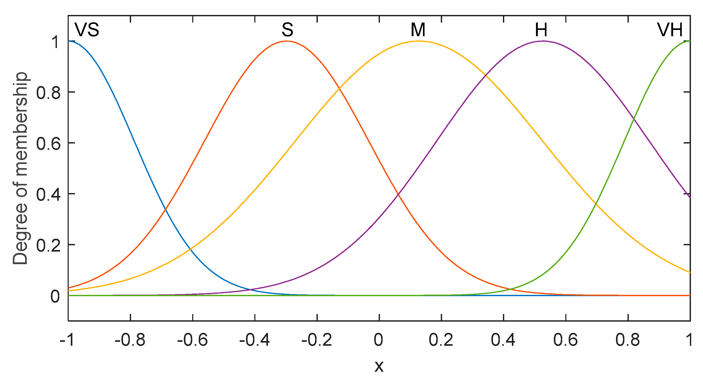
In the FNN estimator, we can specify a set of five decision variables regularly distributed on a universe of discourse [−1,1], as follows:
μ f k = μ g k = e x p [ ( x + 4 1.6 ( k 1 ) 2 ] , k = 1 , , 5  
i = 5, which means that there are 25 rules to estimate the unknown terms. The selected 25 rules can cover the entire space and approximate any non-linear function. The member function degree is illustrated in Figure 8.
The FNN weights are selected as follows:
[ w f w g ] = [ w f 1 w f 2 w f 3 w f 4 w f 5 w g 1 w g 2 w g 3 w g 4 w g 5 ]  
The initial values for the FNN weights are selected in a random way, and the vector of fuzzy basis functions was constructed by (12). Using these gain parameters, the designed AFN-FTSC and existing FTSC are implemented in the following under different operating points of the buck DC/DC converter.

5.2. Experimental Validation

In this part, the efficacy of the suggested AFN-FTSC technique for regulating the output voltage of a buck DC/DC converter is demonstrated through a real-time implementation on dSPACE 1103 platforms (Figure 9). All system parameters are carefully chosen by keeping the practical conditions in mind, which are given in Table 3.
To show the efficacy of the designed AFN-FTSC algorithm, variations in the output reference voltage, input supply voltage, and load resistance are done based on the values in Table 3. However, the nominal output voltage of the converter is set at 50 V with an input voltage of 100 V during the standard conditions, i.e., while considering no disturbances. To deploy the AFN-FTSC algorithm for the buck DC/DC converter, the sampling frequency, and the switching frequency are considered as 200 kHz and 20 kHz, respectively. The superiority of the AFN-FTSC is analyzed against an existing FTSC as proposed in [14] in terms of tracking error, overshoot, and settling time. The performance of the designed AFN-FTSC algorithm is validated under a variety of operating scenarios: variations in input supply voltage, load resistance, and output reference voltage as demonstrated through the following four cases:
  • Controller performance under variations in the load resistance,
  • Controller performance under variations in the input supply voltage,
  • Controller performance under start-up transient,
  • Controller performance under variations in the output reference voltage,
Case I: Output voltage regulation with variations in the load resistance.
In this scenario, the test is conducted to justify the load disturbance rejection capacity of the proposed AFN-FTSC algorithm while making a comparison with the FTSC algorithm. For this purpose, the effects of only variations in the load resistance are considered, while the output reference voltage remains constant at 50 V. In this test, the load resistance of the buck DC/DC converter is decreased from 80 Ω to 40 Ω, conversely. With such changes in the load resistance, the dynamic responses of the Buck DC/DC converter are represented by two states: output voltage (Vo) and inductor current (iL), as illustrated in Figure 10. The output voltage quickly settles down to its reference value without affecting the steady-state behavior while the designed one is used. However, the overshoots are a bit higher with higher settling times, especially at the instant of changes, i.e., at the decrease in load resistance when the existing FTSC is used. Hence, Figure 10a provides an observation that the designed AFN-FTSC controller can stabilize the output voltage very quickly to its desired value without having any significant impact even with a large variation in the load resistance. Figure 10a also confirms the faster settling time with less transient with the AFN-FTSC controller during the post-disturbance operation while making its comparison with the FTSC controller.
Several quantitative factors such as the peak value, overshoot, undershoot, and settling time are calculated to validate the performance of the designed AFN-FTSC against the FTSC, where these values for both controllers are captured in Table 4. The designed AFN-FTSC outperforms the existing FTSC in all aspects that can also be found in Table 4. The next case study analyzes and compares the performance of the designed and existing controllers against variations in the input supply voltage.
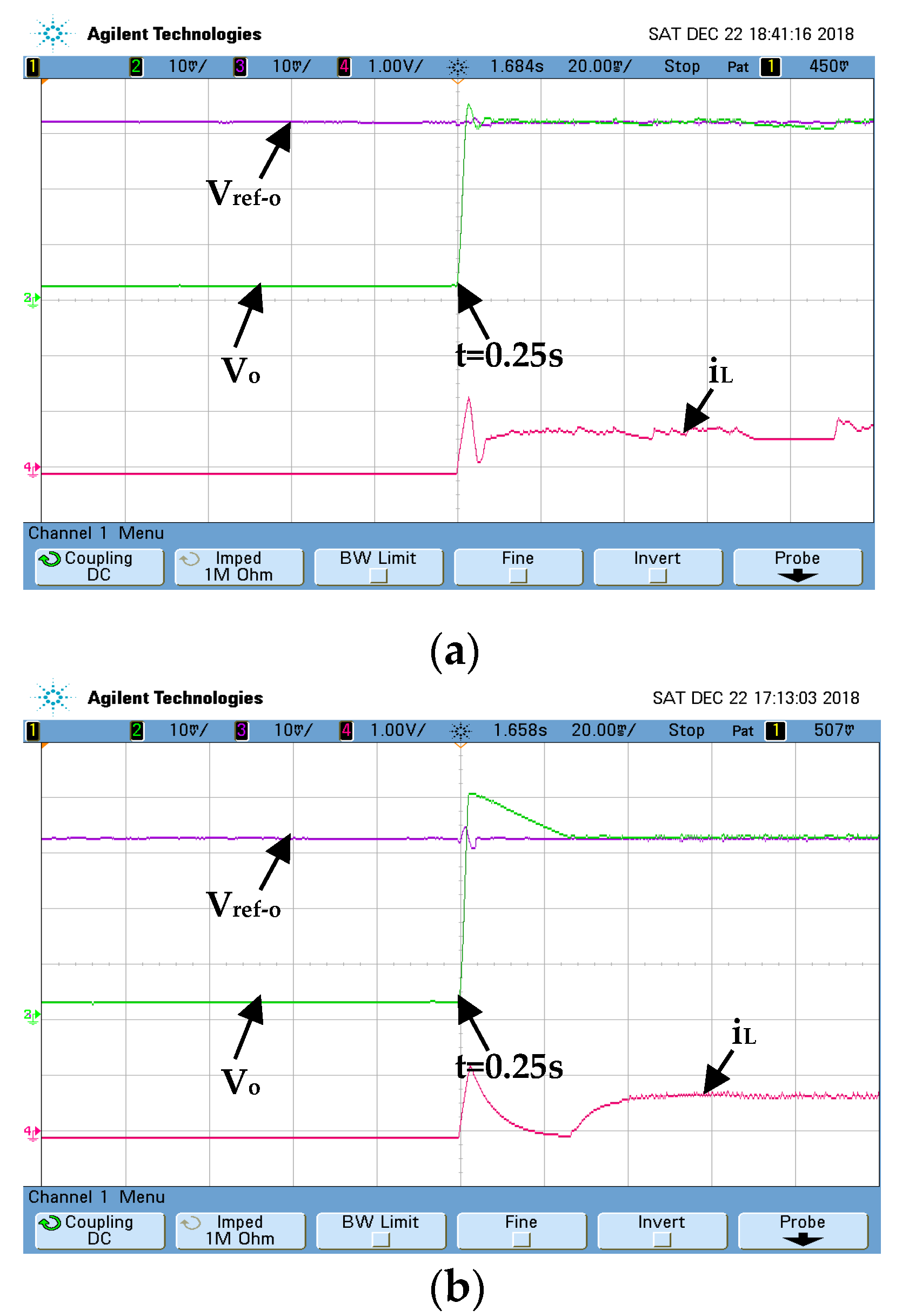
Case II: Output voltage regulation with variations in the input supply voltage
This test considers the variation in the input supply voltage to show the superiority of the designed AFN-FTSC over the existing FTSC algorithm. The input voltage is rated at 0 V at the start of the test, and it is suddenly raised to 100 V at t = 0.25 s. However, the output reference voltage is kept constant at 30 V. The corresponding dynamic responses of different states for the converter are shown in Figure 11. As illustrated in Figure 11a, the designed AFN-FTSC can efficiently eliminate the effects of fluctuations in the input as evidenced by the proper tracking of the output reference voltage. On the other hand, the existing FTSC fails to realize the desired voltage tracking performance when responding to changes in input supply voltage. The result in Figure 11b shows that the FTSC cannot cope with changes in the input supply voltage, however, the designed AFN-FTSC does not experience any problem to maintain the desired performance.
The peak value, overshoot, and settling time are calculated for this scenario and presented in Table 5, which clearly demonstrates the effectiveness of the AFN-FTSC over the FTSC. From Table 5, it can be seen that the output voltage recovery time of the AFN-FTSC is 5 ms, whereas it is 28 ms for the existing FTSC. Furthermore, from Table 5, it can be seen that the voltage fluctuation with the designed AFN-FTSC is 3 V, while it is 11 V with the existing FTSC. In comparison to the existing FTSC controller, the designed AFN-FTSC controller has a shorter settling time and lower voltage changes, as shown by the data analysis.
In the next case, the converter’s reference output voltage variation is regarded as an external perturbation to the converter, which is discussed in the following subsection.
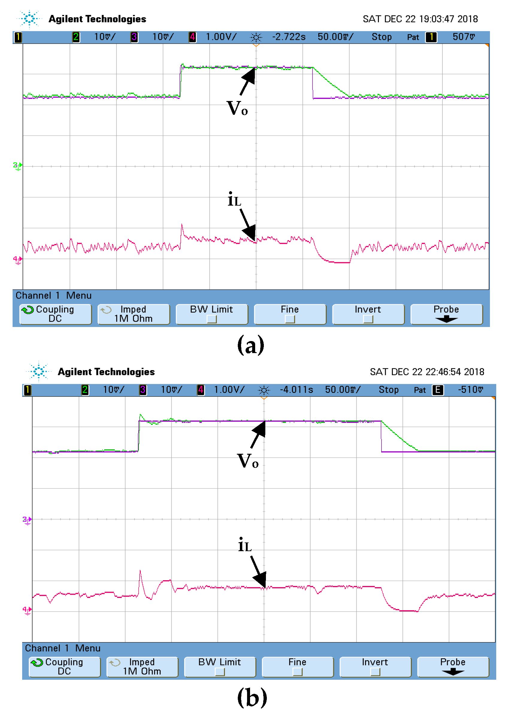
Case III: Output voltage regulation with variations in the output reference voltage.
This test counts variations in the output reference voltage to demonstrate the robustness of both controllers. At the start of the test, the reference voltage is rated at 20 V and then suddenly changed to 30 V and vice-versa. Under this disturbance, the dynamic responses of both states (Vo and iL) are depicted in Figure 12a,b. These responses clearly demonstrate the superior capability of the AFN-FTSC controller (Figure 12a) for tracking output reference voltage, as the existing FTSC controller fails to do so (Figure 12b).
The peak value, overshoot, undershoot, and settling time are calculated for this scenario and presented in Table 6. This table clearly shows very satisfactory performance in terms of both settling time and overshoot with the designed AFN-FTSC over the FTSC.
The voltage tracking capability of each controller is evaluated using a sin-wave reference output voltage. As illustrated in Figure 13, the AFN-FTSC not only offers better precise results, but it also eliminates chattering.
The voltage tracking capability of each controller is evaluated using a triangular-wave reference output voltage (Figure 14). The results indicate the advantage of the considered AFN-FTSC over the FTSC algorithm in terms of output voltage tracking. The studied AFN-FTSC displays a small tracking error (Figure 14a).
Case IV: Output voltage regulation under nominal start-up in the reference voltage.
The purpose of this test is to evaluate the robustness of both controllers under nominal start-up in the output voltage reference. The output voltage of the converter, as presented in Figure 15, is observed for this case, which clearly shows the settling time as almost 5 ms with the AFN-FTSC. However, this settling-time is a bit larger, i.e., around 20 ms if the FTSC is used. Similarly, the FTSC exhibits an overshoot of 20%, while there are no overshoots when the AFN-FTSC is used. Therefore, it is also possible to deduce that the AFN-FTSC method provides a superior dynamic response to the existing FTSC method.
The peak value, overshoot, undershoot, and settling time are calculated for this case study and presented in Table 7. This table clearly shows very satisfactory performance in terms of both maximum overshoot and settling time with the suggested AFN-FTSC over the FTSC. Hence, the overall performance of the AFN-FTSC significantly dominates that of the FTSC for all cases.

5.3. Experimental Validation

A comparative study between the proposed and existing controllers was performed, using integrals of error-based performance indices that are defined as the integral of absolute error (IAE), integral of squared error (ISE), and an integral of time-weighted squared error (ITSE). The mathematical expressions for these indices can be expressed as in [26]:
IAE = 0 T | e ( t ) | dt , ISE = 0 T e ( t ) 2 dt , & I T S E = 0 T te ( t ) 2 dt
where T denotes simulation time with e(t) as the error signal. The smaller value of these indices indicates the better performance, as these indices basically represent the deviation from the ideal condition. All these three indices are calculated for both controllers and presented in Figure 16, which clearly demonstrates significantly smaller values for the AFN-FTSC algorithm when compared with the FTSC algorithm.

6. Conclusions

In this study, a robust regulator is developed by combining the synergetic theory of control (STC) with a terminal attractor method to track the desired output voltage across the load connected to a buck DC/DC converter. The time-varying dynamic reaching law is employed to ensure the finite-time convergence of the tracking voltage errors and the FNN model guarantees the estimation of the unknown converter nonlinear dynamics. Experimental results are analyzed under various conditions including qualitative and quantitative ways. Comparisons were made with an existing FTSC, and the newly designed AFN-FTSC performs better in all conditions. Based on the analyses presented in this study, the key findings can be summarized as:
  • The designed AFN-FTSC properly tracks the reference value of the output voltage with the minimum overshoot and faster settling time—even variations in the input voltage, load resistance, and reference voltage.
  • The steady-state is significantly low under any operating scenario.
The impacts of model perturbations and external disturbances are not incorporated into the mathematical model, although these have been included during the analysis in different platforms. Future work will further improve the AFN-FTSC design process by capturing these impacts within the model.

Author Contributions

Conceptualization, B.B. and F.A.; Data curation, B.B., N.H. and O.A.; Formal analysis, N.H., O.A. and S.A.M.A.; Funding acquisition, F.A. and S.S.M.G.; Investigation, S.S.M.G.; Methodology, B.B., N.H., O.A. and S.A.M.A.; Project administration, B.B., F.A. and S.S.M.G.; Resources, B.B., F.A. and S.S.M.G.; Software, B.B., N.H. and O.A.; Supervision, B.B. and S.S.M.G.; Validation, N.H., O.A. and S.A.M.A.; Visualization, F.A. and S.A.M.A.; Writing—original draft, B.B., N.H. and O.A.; Writing—review & editing, F.A., S.S.M.G. and S.A.M.A. All authors have read and agreed to the published version of the manuscript.

Funding

This work funded by Taif University Researchers Supporting Project TURSP-2020/97, Taif University, Taif, Saudi Arabia.

Acknowledgments

The authors thank Taif University Researchers Supporting Project TURSP-2020/97, through Taif University, Taif, Saudi Arabia for supporting this work.

Conflicts of Interest

The authors declare no conflict of interest.

References

  1. Babes, B.; Boutaghane, A.; Hamouda, N.; Mezaache, M. Design of a robust voltage controller for a dc-dc buck converter using fractional-order terminal sliding mode control strategy. In Proceedings of the International Conference on Advanced Electrical Engineering (ICAEE), Algiers, Algeria, 19–21 November 2019. [Google Scholar]
  2. Amir, M.; Prajapati, A.K.; Refaat, S.S. Dynamic Performance Evaluation of Grid-Connected Hybrid Renewable Energy-Based Power Generation for Stability and Power Quality Enhancement in Smart Grid. Front. Energy Res. 2022, 10, 861282. [Google Scholar] [CrossRef]
  3. Yan, Y.; Liu, J. Analysis of passivity-based sliding-mode control strategy in DC/DC converter. In Proceedings of the Chinese Control Conference, Harbin, China, 7–11 August 2006; pp. 171–174. [Google Scholar]
  4. Young, D.S.; Hen, T.-W.; Santi, E.; Monti, A. Synergetic control approach for induction motor speed control. In Proceedings of the Annual Conference of IEEE Industrial Electronics Society, Busan, Korea, 2–6 November 2004. IECON 2004. [Google Scholar]
  5. Dehri, K.; Nouri, A.S. A discrete repetitive adaptive sliding mode control for DC-DC buck converter. Inst. Mech. Eng. Part I J. Syst. Control. Eng. 2021, 235, 1698–1708. [Google Scholar] [CrossRef]
  6. Chen, J.J.; Hwang, Y.S.; Lin, J.Y.; Ku, Y. A dead-beat-controlled fast-transient-response buck converter with active pseudo-current-sensing techniques. IEEE Trans. Very Large Scale Integr. (VLSI) Syst. 2019, 27, 1751–1759. [Google Scholar] [CrossRef]
  7. Kumar, V.I.; Kapat, S. Mixed-signal hysteretic internal model control of buck converters for ultra-fast envelope tracking. In Proceedings of the IEEE Applied Power Electronics Conference and Exposition (APEC), Long Beach, CA, USA, 20–24 March 2016; pp. 3224–3230. [Google Scholar]
  8. Linares-Flores, J.; Hernandez Mendez, A.; Garcia-Rodriguez, C.; Sira-Ramirez, H. Robust nonlinear adaptive control of a boost converter via algebraic parameter identification. IEEE Trans. Ind. Electron. 2014, 61, 4105–4114. [Google Scholar] [CrossRef]
  9. Xu, Q.; Yan, Y.; Zhang, C.; Dragicevic, T.; Blaabjerg, F. An offset-free composite model predictive control strategy for DC/DC buck converter feeding constant power loads. IEEE Trans. Power Electron. 2020, 35, 5331–5342. [Google Scholar] [CrossRef]
  10. Hausberger, T.; Kugi, A.; Eder, A.; Kemmetmüller, W. High-speed nonlinear model predictive control of an interleaved switching DC/DC-converter. Control. Eng. Pract. 2020, 103, 104576. [Google Scholar] [CrossRef]
  11. Albira, M.E.; Zohdy, M.A. Adaptive model predictive control for DC-DC power converters with parameters uncertainties. IEEE Access 2021, 9, 135121–135131. [Google Scholar] [CrossRef]
  12. Hamouda, N.; Babes, B.; Boutaghane, A. Design and analysis of robust nonlinear synergetic controller for a PMDC motor driven wire-feeder system (WFS). In Lecture Notes in Electrical Engineering; Springer: Singapore, 2020; pp. 373–387. [Google Scholar]
  13. Babes, B.; Boutaghane, A.; Hamouda, N. Design and real-time implementation of an adaptive fast terminal synergetic controller based on dual RBF neural networks for voltage control of DC–DC step-down converter. Electr. Eng. 2021, 104, 945–957. [Google Scholar] [CrossRef]
  14. Hamouda, N.; Babes, B. A DC/DC Buck converter voltage regulation using an adaptive fuzzy fast terminal synergetic control. In Lecture Notes in Electrical Engineering; Springer: Singapore, 2020; pp. 711–721. [Google Scholar]
  15. Hadjer, A.; Ameur, A.; Harmas, N.M. Adaptive non-singular terminal synergetic power system control using PSO. In Proceedings of the 8th International Conference on Modellin, Identification and Control (ICMIC-2016), Algiers, Algeria, 15–17 November 2016. [Google Scholar]
  16. Babes, B.; Boutaghane, A.; Hamouda, N.; Mezaache, M.; Kahla, S. A robust adaptive fuzzy fast terminal synergetic voltage control scheme for DC/DC buck converter. In Proceedings of the International Conference on Advanced Electrical Engineering (ICAEE), Algiers, Algeria, 19–21 November 2019. [Google Scholar]
  17. Wen, S.; Chen, M.Z.Q.; Zeng, Z.; Huang, T.; Li, C. Adaptive neural-fuzzy sliding-mode fault-tolerant control for uncertain nonlinear systems. IEEE Trans. Syst. Man Cybern. Syst. 2017, 47, 2268–2278. [Google Scholar] [CrossRef]
  18. Chen, Z.; Li, Z.; Chen, C.L.P. Adaptive neural control of uncertain MIMO nonlinear systems with state and input constraints. IEEE Trans. Neural Netw. Learn. Syst. 2017, 28, 1318–1330. [Google Scholar] [CrossRef]
  19. Santi, E.; Monti, A.; Proddutur, D.; Li, K.; Dougal, R.A. Synergetic control for power electronics applications: A comparison with the sliding mode approach. J. Circuits Syst. Comput. 2004, 13, 737–760. [Google Scholar] [CrossRef] [Green Version]
  20. Shahgholian, G. Power system stabilizer application for load frequency control in hydro-electric power plant. Int. J. Theor. Appl. Math. 2017, 3, 148. [Google Scholar] [CrossRef] [Green Version]
  21. Rubaai, A.; Young, P. Hardware/software implementation of fuzzy-neural-network self-learning control methods for brushless DC motor drives. IEEE Trans. Ind. Appl. 2016, 52, 414–424. [Google Scholar] [CrossRef]
  22. Nettari, Y.; Kurt, S. Design of a new non-singular robust control using synergetic theory for DC-DC buck converter. Electrica 2018, 18, 292–329. [Google Scholar] [CrossRef] [Green Version]
  23. Zerroug, N.; Harmas, M.N.; Benaggoune, S.; Bouchama, Z.; Zehar, K. DSP-based implementation of fast terminal synergetic control for a DC–DC Buck converter. J. Frankl. Inst. 2018, 355, 2329–2343. [Google Scholar] [CrossRef]
  24. Ullah, N.; Shaoping, W. High performance direct torque control of electrical aerodynamics load simulator using adaptive fuzzy backstepping control. Proc. Inst. Mech. Eng. Part G J. Aerosp. Eng. 2015, 229, 369–383. [Google Scholar] [CrossRef]
  25. Sastry, S.; Bodson, M. Adaptive Control: Stability, Convergence, and Robustness; Englewood Cliffs, N.J., Ed.; Prentice-Hall: Hoboken, NJ, USA, 1989. [Google Scholar]
  26. Babes, B.; Mekhilef, S.; Boutaghane, A.; Rahmani, L. Fuzzy Approximation-Based Fractional-Order Nonsingular Terminal Sliding Mode Controller for DC–DC Buck Converters. IEEE Trans. Power Electron. 2022, 37, 2749–2760. [Google Scholar] [CrossRef]
  27. Alanqar, A.; Durand, H.; Albalawi, F.; Cristofides, P.D. An economic model predictive control approach to integrated production management and process operation. AIChE J. 2017, 63, 1892–1906. [Google Scholar] [CrossRef]
Figure 1. Convergence of macro-variable for various starting locations to the attractor.
Sustainability 14 07967 g001
Figure 2. Geometric description of SC in the phase plane.
Sustainability 14 07967 g002
Figure 3. Schematic diagram of the proposed SC algorithm.
Sustainability 14 07967 g003
Figure 4. Structure of a FNN approximator with four layers.
Sustainability 14 07967 g004
Figure 5. The circuit model of buck DC/DC converter.
Sustainability 14 07967 g005
Figure 6. Block diagram for proposed AFN-FTSC controller.
Sustainability 14 07967 g006
Figure 7. The output voltage of the converter for different values of (p/q) with the designed controller.
Sustainability 14 07967 g007
Figure 8. Membership function of x.
Sustainability 14 07967 g008
Figure 9. The experimental prototype of the buck DC/DC converter.
Sustainability 14 07967 g009
Figure 10. Dynamic performance of the converter under load-resistance variations (Vo: 10 V/div, iL: 0.25 A/div and time: 100 ms/div): (a) AFN-FTSC controller, (b) FTSC controller.
Sustainability 14 07967 g010
Figure 11. Dynamic performance of the converter under input supply voltage variations (Vo: 10 V/div, iL: 0.5 A/div and time: 20 ms/div): (a) AFN-FTSC controller, (b) FTSC controller.
Sustainability 14 07967 g011
Figure 12. Dynamic performance of the converter under output reference voltage variations (Vo: 10 V/div, iL: 0.5 A/div and time: 50 ms/div): (a) AFN-FTSC controller, (b) FTSC controller.
Sustainability 14 07967 g012
Figure 13. Dynamic performance of the converter under sinusoidal wave in the output voltage reference (Vo: 10 V/div, iL: 0.5 A/div, and time: 1 s/div): (a) AFN-FTSC controller, (b) FTSC controller.
Sustainability 14 07967 g013
Figure 14. Dynamic responses of the converter with triangular-wave variations in the output voltage reference (Vo: 10 V/div, iL: 0.25 A/div and time: 2 s/div): (a) AFN-FTSC controller, (b) FTSC controller.
Sustainability 14 07967 g014
Figure 15. Dynamic responses of the converter under nominal start-up in the output voltage reference (Vo: 10 V/div, iL: 0.25 A/div and time: 20 ms/div): (a) AFN-FTSC controller, (b) FTSC controller.
Sustainability 14 07967 g015
Figure 16. Integral-error-performance indices: (a) IAE, (b) ISE, and (c) ITSE.
Sustainability 14 07967 g016
Table 1. Parameter sensitivity analysis.
p/q1.11.51.82.0
Voltage overshoot (V)15.850.130.110.07
Settling-time (ms)42.969.4427.6075.44
Table 2. Regulator Specifications.
RegulatorParametersGain Value
AFN-FTSCκ0.005
a200
b300
p3
q2
µ1500
µ2800
FTSCκ0.005
a200
b300
p3
q2
Table 3. System Parameters.
ParameterValue
Vin100 V
Ro40/80/40 Ω
Vo_red20/30/50 V
L7 mH
C800 μF
fs20 kHz
Table 4. Peak value, overshoot, undershoot, and settling time with variations in the load.
ControllerPeak Value (V)Overshoot (%)Undershoot (%)Settling Time (ms)
AFN-FTSC006.662
FTSC8164020
Table 5. Peak value, overshoot, and settling time with variations in the input voltage.
Control StrategyPeak Value (V)Overshoot (%)Undershoot (%)Settling Time (ms)
AFN-FTSC31005
FTSC1136.66028
Table 6. Peak value, overshoot, undershoot, and settling time with variations in the reference voltage.
Control StrategyPeak Value (V)Overshoot (%)Undershoot (%)Settling Time (ms)
AFN-FTSC0002
FTSC26.66040
Table 7. Peak value, overshoot, undershoot, and settling time with variations in reference voltage.
ControllerPeak Value (V)Overshoot (%)Undershoot (%)Settling Time (ms)
AFN-FTSC3205
FTSC1020020
Publisher’s Note: MDPI stays neutral with regard to jurisdictional claims in published maps and institutional affiliations.

