1. Introduction
1.1. Background and Motivation
Wind, solar PV, tidal and biomass-based distributed generation have recently gained popularity as a way to meet rising load demand while reducing fossil fuel use and addressing global climate change concerns [
1,
2,
3]. However, due to the high potential installation cost of renewable energy sources (RESs), it is always preferable to operate them at high efficiency levels [
4,
5]. In order to meet this objective, several existing studies recommended using them in the microgrid (MG) form, which is a local grid made up of diesel power generators (DPGs), energy storage systems (ESSs), and both AC and DC loads [
6]. An MG system can be classified into two categories based on the type of common DC-bus voltage: DCMG and ACMG [
7]. However, the DCMG is gaining more prominence over the ACMG owing to several benefits, such as the fact that it is not essential to synchronize it with the existing grid and it has no frequency and reactive power control [
8,
9].
However, despite the aforementioned benefits of a DCMG, it must overcome several technological and operational difficulties while boosting flexibility and reliability. For example, the DCMG’s DC-bus voltage stability is threatened by the intermittent nature of RESs and the intrinsic nonlinear behavior of power electronic switches [
10]. In this paper, a solar PV unit is used as the main source of power supply whose output voltage is not only changeable but also lower than the desired DC-bus voltage. To manage this situation, the solar PV unit comes with a DDBC that matches the output voltage to the desired DC-bus voltage. Furthermore, a sudden variation in DC load demand causes power fluctuation in a DCMG. Under these conditions, it is challenging to maintain a steady and acceptable DC-bus voltage within the DCMG, even though the power balance in a DCMG is solely responsible for the stability of DC-bus voltage [
11]. Therefore, a constant DC-bus voltage is crucial because if it is not properly managed, it may cause the instability of a DCMG. This difficulty can be resolved by connecting an ESS to the DC-bus, which not only improves the power reliability but also enhances the power balance within the DCMG [
12]. When there is insufficient power from the solar PV to satisfy load demands, an ESS will supply the shortage power to the DC-bus to maintain the power balance. Furthermore, when there is extra power after meeting the load demands, the excess power will be stored in the ESS [
9,
13]. However, to achieve this goal, an ESS must be connected to a BDDC to operate it in boost or buck modes depending on its state of charge and the DC-bus voltage state [
14]. However, an ESS with a BDDC is exceedingly complex and nonlinear due to its nonlinear switching modes. Therefore, it is necessary to incorporate a controller with each component of the DCMG to regulate their switching pulses, which not only manages their corresponding output power properly but also enhances the overall stability of the DCMG.
1.2. Literature Review
In [
15], a PWM-based converter for managing the charging and discharging current operations of a battery ESS (BESS) was proposed in DCMG applications. Even though this converter can achieve the intended DC-bus control goal, its layered design restricts its use. To avoid this limitation, a dual active bridge (DAB)-based converter was proposed in [
16]. To control the DC-bus voltage while guaranteeing accurate load current sharing in a DCMG, a droop control approach was proposed in [
17,
18]. However, due to voltage drop effects across the line impedance, the fundamental disadvantage of a droop controller is that it decreases the precision of load current sharing [
19]. To overcome the disadvantage of a droop controller, a fuzzy logic control (FLC)-based gain-scheduling controller was proposed in [
20] for DCMG applications. The proposed approach was able to correctly manage the DC-bus voltage while offering an optimal power balance. Another PI-based FLC approach for regulating the DC-bus voltage and smoothing the power flow in a DCMG was proposed in [
21]. However, the fundamental disadvantage of the FLC is that the system dynamics cannot be adequately represented due to the lack of dynamical models. Furthermore, the above-mentioned controllers were not able to offer the desired control performance under changing operating points as these controller were designed based on linear models [
22,
23]. On the other hand, a DCMG is a highly nonlinear system due to the inclusion of multiple power electronics converters. Therefore, nonlinear controllers have received a lot of attention which is not only capable of providing stable functioning in a wide variety of operating situations but also can overcome the limitations of linear controllers.
To overcome the limitations of linear controllers, a model predictive controller (MPC) was proposed in [
24] to minimize the impact of pulse load on a DCMG. Using the same approach, the power balance in a DCMG was ensured in [
25,
26]. However, the application of these control mechanisms is limited due to the necessity for lengthy and pointless computations. This constraint can be avoided by employing a nonlinear feedback linearization control (FBLC) approach, which has been successfully used in DCMG applications owing to its canceling capability of nonlinear terms. A nonlinear FBLC approach for regulating the DC-bus voltage and preserving power balance inside a DCMG was proposed in [
27]. Though MPC and FBLC schemes can improve the DC-bus voltage regulation, the intended control goal is dependent on precise system parameter information. On the other hand, these parameters can be quickly modified when an operating point is changed, so obtaining accurate system parameters information is challenging in practice. To address this issue, in [
28], an adaptive FBLC was proposed in which unknown system properties were projected using adaptation laws while the MG’s power-sharing capabilities were enhanced. Although the proposed approach can handle the parametric uncertainty issues, this control strategy occasionally suppresses crucial nonlinear aspects, which might assist in improving the system’s transient stability. In this regard, the nonlinear backstepping controller (BSC) is an effective control approach for avoiding the constraints of FBLCs [
29].
In [
30,
31], a BSC for improving the dynamic stability of a DCMG under various operating situations was proposed. Even though the proposed controller can maintain and enhance the power balance in the DCMG, the parameter uncertainties were not taken into account. Thus, to solve this constraint, an adaptive BSC for enhancing DC-bus voltage regulation while preserving the power balance in the presence of parametric uncertainty was proposed in [
30,
32]. Although the control strategies as presented in [
30,
31,
32] can provide the desired control goal, computing a derivative for each virtual control variable is quite complicated and creates some difficulties during the practical implementation. Furthermore, to achieve optimal performance, precise adjustment of the user-defined constants is necessary, which adds to the complexity of the practical implementation.
The nonlinear sliding mode control (SMC) scheme, as detailed in [
33,
34], is a viable solution for overcoming the limitations of BSCs and FBLCs. In [
35,
36], a nonlinear SMC for DC-DC converters was described to manage the bidirectional power flow between DCMG components and the DC-bus. However, because of their incapacity to deal with system uncertainties, these controllers need precise circuit settings. Therefore, an adaptive SMC was proposed in [
37,
38] to increase resistance against parametric uncertainty. However, due to the high-frequency fluctuation near the sliding surface, known as the “chattering effect”, standard SMC is not a suitable control system for practical applications. Thus, current research has offered a number of ways to reduce chattering, including super-twisting SMC [
33], nonsingular fast terminal SMC [
39], and reaching law-based methodology [
40]. The reaching law-based technique might be able to successfully address the chattering problem since it works directly on the reaching phase of SMC schemes. As a consequence, a nonlinear integral terminal SMC (ITSMC) in conjunction with a modified reaching law is proposed in this work to improve the dynamic stability of the solar PV and BESS-based DCMG, addressing the concerns posed by existing nonlinear control approaches. To the best of the author’s knowledge, this method is not employed in DCMG applications yet to adjust the DC-bus voltage while preserving power balance.
1.3. Contribution
The main aim of this paper is to smooth power flow between the generator and the load while regulating DC-bus voltage in an acceptable range of operating conditions. To achieve this aim, a nonlinear ITSMC based on a modified reaching law is proposed in this research work. An accurate dynamical model for each component of the DCMG is constructed to aid the proposed controller design. Then, the recommended control approach is applied to each component to obtain the necessary control signal. The candidate Lyapunov function theorem is used to confirm the DCMG’s stability with the stated control scheme. As compared to the present literature, the major contribution of this work can now be summarized as follows:
The solar PV unit and the BESS work in conjunction to ensure generation-load power balance while keeping the DC-bus voltage within an acceptable operating range.
To improve the sliding phase’s steady-state tracking performance, a modified integral terminal sliding surface (ITSS) is proposed.
A newly modified reaching law is proposed, which can confirm the finite-time convergence of the ITSS in a faster way as compared to the conventional reaching law.
The control law is derived by satisfying the Lyapunov stability theorem. Therefore, the proposed controller surpasses existing controllers in terms of overall stability when paired with an energy management system. The BESS unit also aids the solar PV unit in fulfilling the DCMG’s goal by supplying power to DC loads independently.
Extensive simulation results are used to illustrate the usefulness of the proposed controller under fluctuating of solar irradiation and load demand. In addition, the simulation results are compared to those of previously designed controllers.
1.4. The Organization of this Paper
The rest of this work is arranged in the following way. The solar PV unit and the BESS are coupled in
Section 2 to form a DCMG.
Section 3 discusses the operational modes along with the power management within the DCMG. In
Section 4, the dynamical model of the DCMG components is described.
Section 5 examines the designed controller’s design process.
Section 6 presents the results of the simulation, while
Section 7 summarizes the research contributions of this work and considers future prospects.
2. DCMG Configuration
Figure 1 represents the overall configuration of the proposed DCMG, which has the following components:
A solar PV unit based on maximum power point tracking (MPPT) that is linked to the DC-bus through a DDBC;
A BESS, which is used to smooth the power flow within the DCMG. To control the charging and discharging current of the BESS, a BDDC is used in between it and the common DC-bus;
DC loads, which are connected to the DC-bus directly; and
Finally, it has a 120 V DC-bus, to which all components are connected either directly or through a power electronics converter.
The solar PV unit will be the major power source in this design, while a BESS will be employed to maintain power balance by storing excess power during light load scenarios and supplying surplus load-demanding power to the DC-bus during peak load situations. Based on this discussion, the net power could be expressed as follows:
where
is the BESS output power, which is positive during discharging mode and negative during charging mode,
is the power consumed by DC loads,
is the net power,
is the SPV output power and
is the loss power. As discussed above, the DDBC and BDDC assist in maintaining a constant DC-bus voltage and power balance in a DCMG system. The dynamic of the DC-bus voltage in terms of the net power can be described as follows [
30]:
where the DC-bus capacitor is denoted by
. A constant DC-bus voltage indicates a balanced power flow into a DCMG according to Equation (
2). The rise or decrease in DC-bus voltage, on the other hand, indicates a power surplus or deficiency inside the DCMG. By managing the BESS’s power flow, the proposed controller in this work will keep the BESS’s state of charge
in a safe operational condition while maintaining a constant DC-bus voltage. The operational modes based on power balance are discussed in the next section.
3. DCMG Operational Modes
The output power of the SPV unit will be changed with changes in solar irradiance and temperature. Therefore, when the total power generation is less than the total load power, the DC-bus voltage may deviate from its reference value. In this situation, to maintain the power balance while keeping a constant DC-bus voltage, the BESS will supply the shortage power. Again, if the generated power is greater than the total load power, the extra power will be stored in the BESS. However, owing to unforeseen circumstances, such as a shortage of the solar PV unit power, particularly at night, the BESS capacity may be reduced below its minimal limitations. In such scenarios, maintaining the DC-bus voltage at the desired level is a challenging task. To avoid the DCMG from collapsing, load shedding should be done on a priority basis. To represent the above scenarios, the proposed DCMG will function in four operational modes based on the total power generation by the solar PV unit, the of the BESS, and total load demand, as discussed below:
Mode I ( and )
In this mode, the solar PV’s output power exceeds the total load demand. Depending on the battery’s , extra power will be stored into the BESS via the buck mode of the BDDC. While charging the battery, the solar PV unit will remain in the MPPT mode to preserve power balance within the DCMG.
Mode II ( and )
This mode will be initiated when the solar PV power is less than the load demand. The difference between solar PV power and total load demands will be smaller than the rated battery power in this mode, and if the battery is more than the minimum threshold, the BESS will make up the difference.
Mode III ( and )
In this mode, the solar PV unit’s power exceeds the whole load requirement, and the BESS is fully charged. As a result, the BESS should be disconnected from the system to avoid overcharging, and the solar PV unit should be set to power curtailment mode.
Mode IV ( and )
The power from the solar PV unit is insufficient to meet the total load need in this mode, and the BESS is entirely drained at the same time. As a result, to avoid undercharging, the BESS should be disconnected. Furthermore, the solar PV unit should be in MPPT mode at this time, and load shedding will be used to maintain power balance within the DCMG. However, it should be emphasized that this mode is not represented in our simulation findings. This is due to the fact that in order to achieve this mode, specifically to make during the simulation, the simulation must be conducted for an extended period of time.
It is evident from the preceding explanation that the overall stability of the DC-bus voltage is reliant on the stability of each component when supplying power to the load. To achieve this purpose, a proper model of each unit is necessary, which is discussed in detail in the next section.
4. Modeling of Each Microgrid Component
In this section, each component of the DCMG is modeled separately based on its features and constraints, which are discussed in the following subsections.
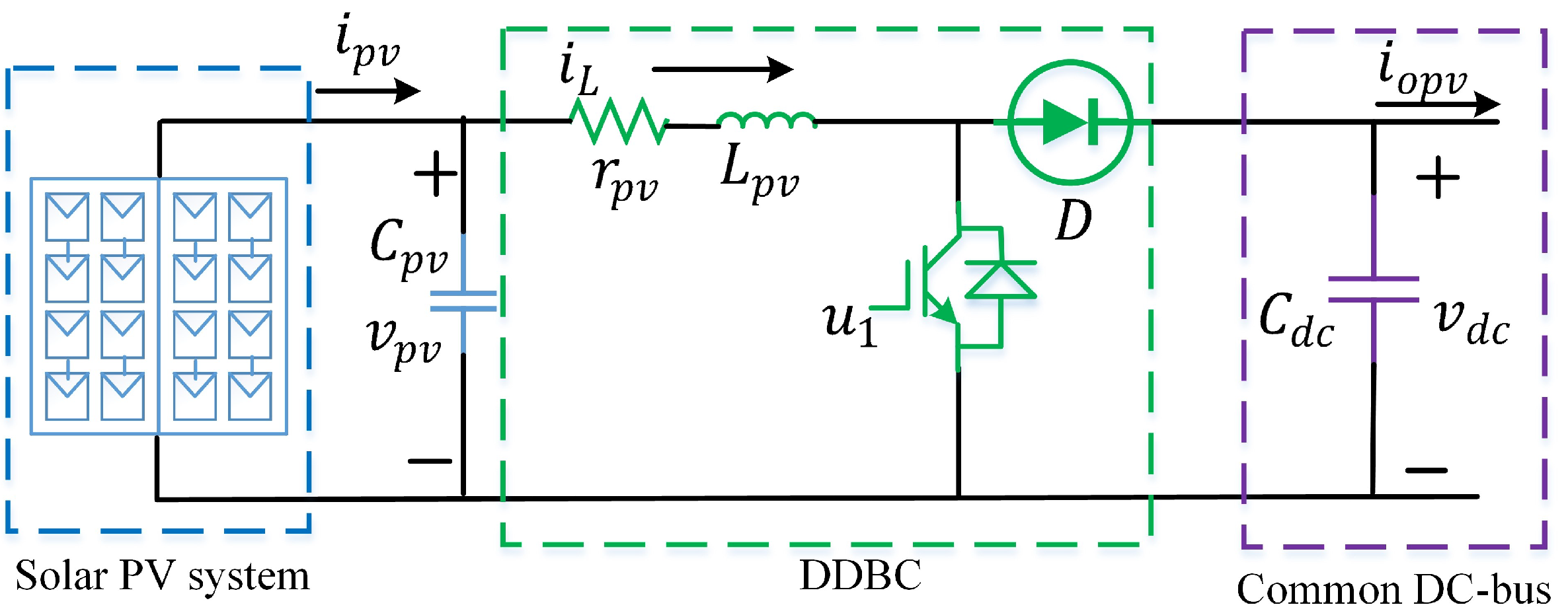
4.1. DDBC Model for the Solar PV
The analogous circuit layout of a solar PV unit with a DDBC is shown in
Figure 2. From
Figure 2, using Kirchhoff’s voltage and current laws, the mathematical model can be introduced as follows [
9]:
where
,
,
,
, and
are the solar PV unit’s output voltage, the current flowing through the internal inductance
, and resistance
of the converter, DC-bus capacitance, load current, and control signal, respectively. To ensure robustness against measurement noise, it is essential to consider the uncertainties within the dynamical model. As a result, Equation (
3) can be changed by including external disturbances as follows:
where
and
are used to represent the external disturbances.
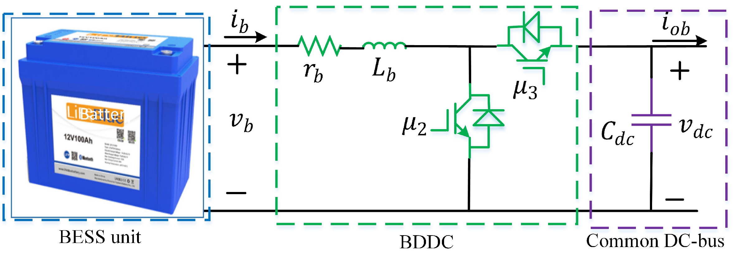
4.2. BDDC Model for the BESS
Figure 3 shows the equivalent circuit of a BESS with a BDDC. Based on this equivalent circuit, the dynamical model can be expressed as [
9]:
where
,
,
,
,
, and
are used to represent the output current of the BESS, the terminal voltage of the battery, the inductance of the converter, the internal resistance of the inductance, the load current, and the switching control signal, respectively. By including external disturbances, Equation (
5) can be rewritten as follows:
where
and
are used to represent external disturbances.
To ensure the DCMG’s steady and efficient transient operation, effective control methods must be developed. In the following section, the proposed controller will be designed based on the models provided by Equations (
4) and (
6), respectively.
5. Proposed Controller Design
The goal of this paper is to maintain power balance when the DCMG is working in various modes. To meet that goal, it is essential to keep the solar PV unit at its MPP and manage the BESS’s charging and discharging modes. To obtain the control signals of these units, the design technique of the proposed controller is presented in the following sections.
5.1. Controller Design for the DDBC
The design approach of the ITSMC based on a MERL for the boost converter is presented in this part to get the control law. It is well-known that the design of any SMC generally has two phases. In the first phase, the sliding surface must be carefully selected to provide the desired stability and dynamic performance. In the second phase, an appropriate reaching law and equivalent control law should be selected to reduce reaching time while minimizing the effect of uncertainties.
5.1.1. Design Steps
To develop the proposed ITSMC by employing a MERL, the following conditions must be met:
where
is the sliding surface. The tracking errors
and
for the inductor current and DC-bus voltage, respectively, can be defined as follows:
where
is the inductor reference current and
K is the proportional gain constant. The tracking error dynamics can be described using Equation (
4) as follows:
where
,
,
, and
.
As previously stated, the selection of a sliding surface in terms of tracking errors is always the first step in the design of an SMC. Thus, an integral terminal sliding surface (ITSS) is defined as follows:
where
with
is a positive design constant and
with
is a positive tuning parameter for the proposed ITSS, which will be
. It is worth mentioning that, to enhance overall performance, it is always better to reduce chattering and successfully enhance finite convergence. To achieve this control goal, the control law
can be built based on a constant rate reaching law (CRRL), which fulfills
. The CRRL can be expressed as follows [
40]:
where
is a positive design constant. At this time, the reaching time
for
can be obtained by integrating Equation (
11) with respect to time, which can be expressed as follows:
where
is the initial value of
. From Equation (
12), it can be seen that the reaching time is inversely proportional to
. If the value of
is higher, the reaching time will be smaller, but the chattering level will be higher. To address this limitation, a new MERL is presented in this paper which not only increases the system resilience but also reduces chattering. The proposed reaching law can be expressed as follows:
where
,
, and
. At this point, the sliding surface’s dynamic can be described as follows:
The substitution of
and
from Equation (
9) into Equation (
14) will yield:
where
,
,
and
Now, combining Equations (
13) and (
15), it will yield:
From Equation (
16), the control law can be selected as follows:
Finally, using Equation (
17), Equation (
15) can be reduced to:
Unknown terms cannot be included in a control signal since they will not be available during implementation. In this case, the Lyapunov function can be used to assure the system’s global stability in the presence of uncertainties, which is discussed in the following.
5.1.2. Stability Analysis
The Lyapunov function, which specifies the energy of the system, is used to investigate the stability of the proposed controller. The Lyapunov function, often known as the energy function, is expressed as follows:
It is widely known that
must be negative or semi-definite, i.e.,
, or negative definite, i.e.,
, to assure the system’s overall stability and resilience when employing the control law as described by Equation (
17). Now, the derivative of
can be written as:
Putting the value of
from Equation (
18) into Equation (
20) will yield:
with
. It is necessary that
be equal to or less than zero in order to meet the Lyapunov stability criterion. As a result, the external uncertainties can be constrained as follows to determine the stabilization boundary:
Hence, from Equations (
21) and (
22), it can be seen that
if
or
if
, and it ensures the overall stability of the system. Now, it is necessary to examine the reachability of the MERL to observe the convergence of the ITSS to an equilibrium point within a finite time, which is explained in the following.
5.1.3. Reachability Analysis
In this section, the reaching time of the MERL will be calculated, and it will ensure a faster reaching time as compared to the reaching time of existing reaching laws for the same value of .
Proof. By ignoring the second terms of Equation (
13), it can be rewritten as:
Let us consider
as the reaching time for Equation (
13). Now, by integrating both sides of Equation (
23) from zero to
, the following equation can be obtained:
It will result as follows after the mathematical manipulation:
Equation (
25) can be written as follows when
:
Similarly, when
:
The following expression is obtained by combining Equations (
26) and (
27):
Since
, Equation (
28) can be rewritten as follows:
If the parameter
is appropriately adjusted, Equation (
29) could be constructed as follows:
As
is a strictly positive offset, then it follows that:
Hence, from Equation (
31), it is clear that the first term’s reaching time is less than the conventional reaching time. Furthermore, the second term of MERL can boost the speed of reaching phase. Therefore, it is obvious that the MERL’s dynamic responsiveness is faster than the traditional reaching law’s. The proposed design methodology for the BDDC is presented in the next subsection. □
5.2. Controller Design for the BDDC
The controller design process used by the BESS’s BDDC is the same as explained in the preceding subsection. As a result, the entire design method is not repeated in this subsection to avoid duplication. Using the same approach, the control law for the BDDC can be constructed as follows:
where
and
are positive constant parameters,
,
,
is the reference value of
m which is obtained as:
with a proportional gain
,
,
, and
. In the next part, simulation studies are used to assess the performance of the designed controller.
6. Simulation Results and Discussion
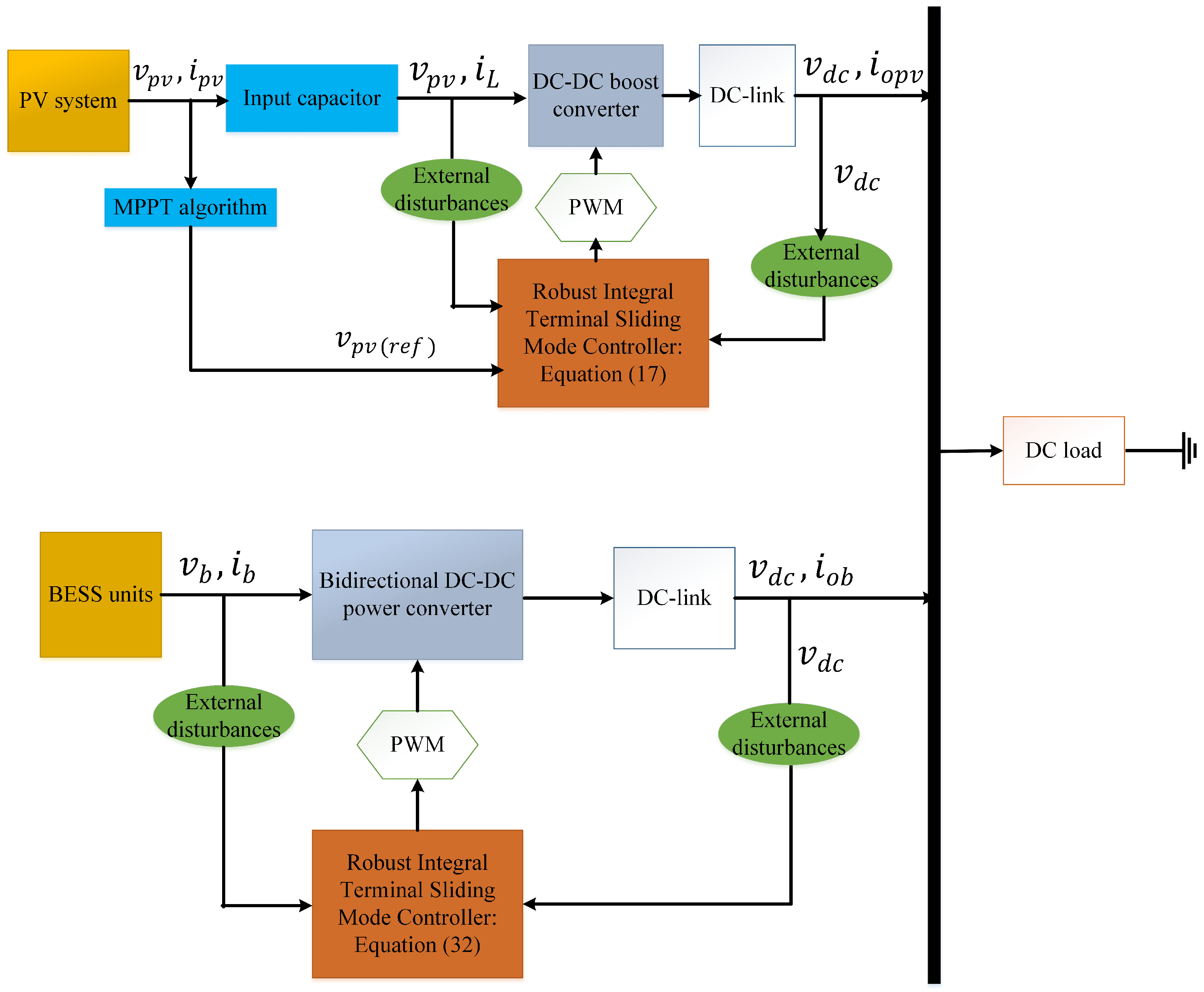
Numerical simulation results are used to assess the proposed controller’s performance. To perform the simulation, the MATLAB/Simulink platform is used in this paper. The implementation of the proposed DCMG in
Figure 1 us shown in
Figure 4. Therefore, during the simulation, the nominal DC-bus voltage is set at 120 V along with the DC-bus capacitor value of 1 mF. Under normal working circumstances, the maximum output power of the solar PV unit is projected to be 10 kW. The maximum load power is predicted to be 15 kW. Apart from that, a BESS is made up of a lithium-ion battery with a voltage of 48 V DC, a capacity of 200 Ah, and internal resistance of 0.025
. During the simulation, the switching frequency of each converter is set to 5 kHz, with a sampling frequency of 10 kHz.
Table 1 summarizes all of this information.
The controller’s performance is evaluated under a variety of circumstances, including variations in solar irradiation and load fluctuations. The performance of the developed controller is also compared to existing control approach 1 in [
33] and existing control approach 2 in [
30] to demonstrate its superiority. When there is a power shortage, the BESS will deliver the necessary power to the load; when power is sufficient, the BESS will absorb the surplus power from the DC-bus. During the simulation, the solar PV unit is turned on first to provide the DC-bus voltage, followed by the BESS and DC loads. Various operational scenarios are simulated to confirm the solar PV and BESS performance in regulating the DC-bus voltage while delivering power to loads. These scenarios are presented in the following.
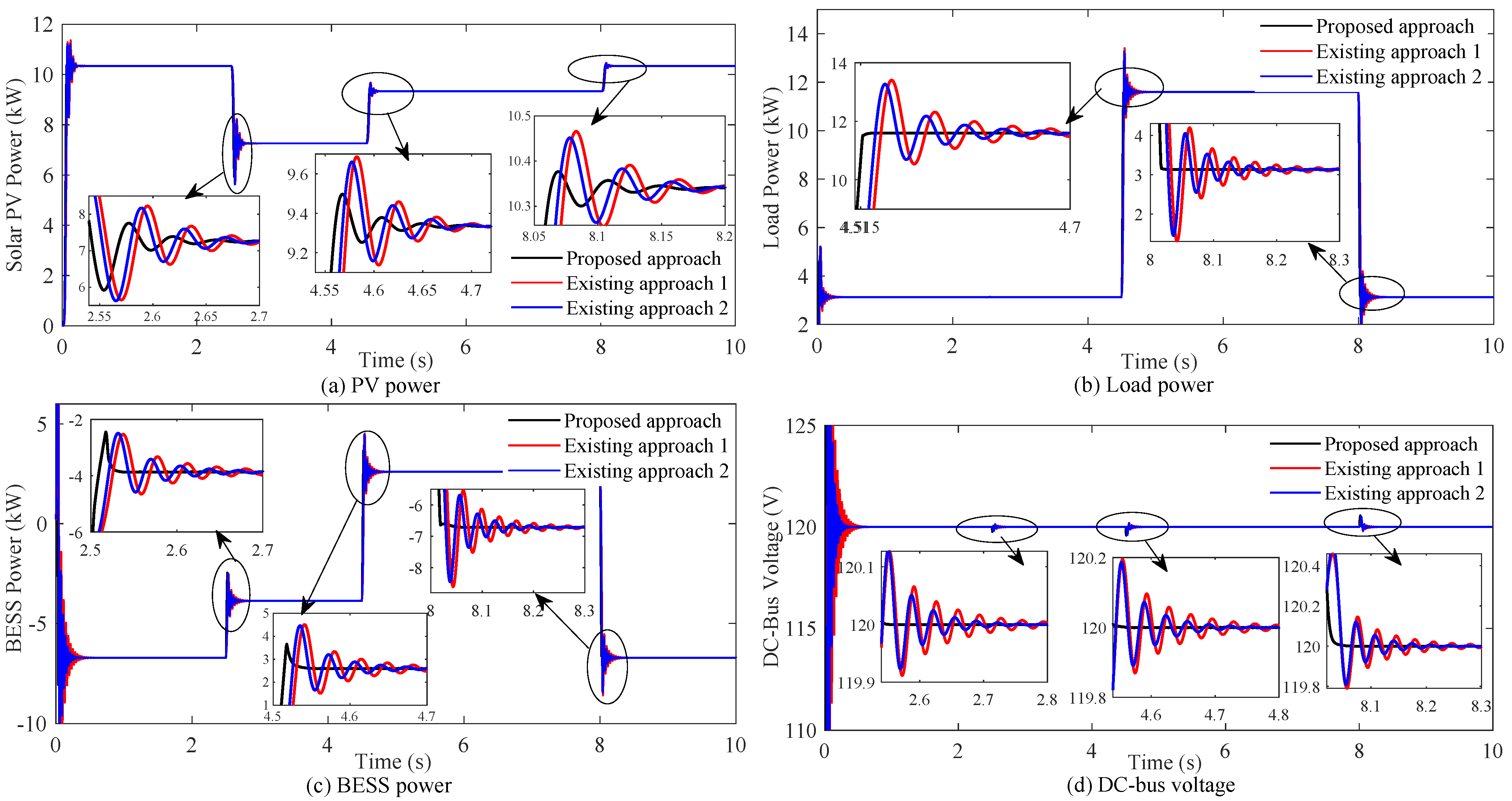
Initially, it is considered that the solar PV unit is operating at standard operating conditions. However, at t = 2.5 s, the power generation by the solar PV unit decreases from 10.34 kW to 7.26 kW due to the change in atmospheric conditions while the load power demand is kept constant at 3.122 kW.
Figure 5 shows the simulation results for the proposed approach and existing control schemes. From
Figure 5, it is obvious that for this time interval, the generating power is greater than the total load demand. Therefore, the DC-bus voltage surpasses 120 V since the solar PV power exceeds the load power needs. Under this situation, the BESS instantaneously absorbs a surplus power of 6.717 kW for a short period to maintain power balance while regulating the DC-bus voltage to 120 V. From
Figure 5d, it can be observed that the existing controllers and proposed controller have settling times of 300 ms, 200 ms, and 3 ms, respectively. In comparison to the existing control techniques, the proposed control scheme is around four times quicker. The overshoot of the proposed controller and existing controllers are demonstrated in
Table 2,
Table 3,
Table 4 and
Table 5. According to the findings that are demonstrated in
Figure 5 and
Table 2,
Table 3,
Table 4 and
Table 5, the proposed controller outperforms the existing control schemes in terms of setting time and overshoot.
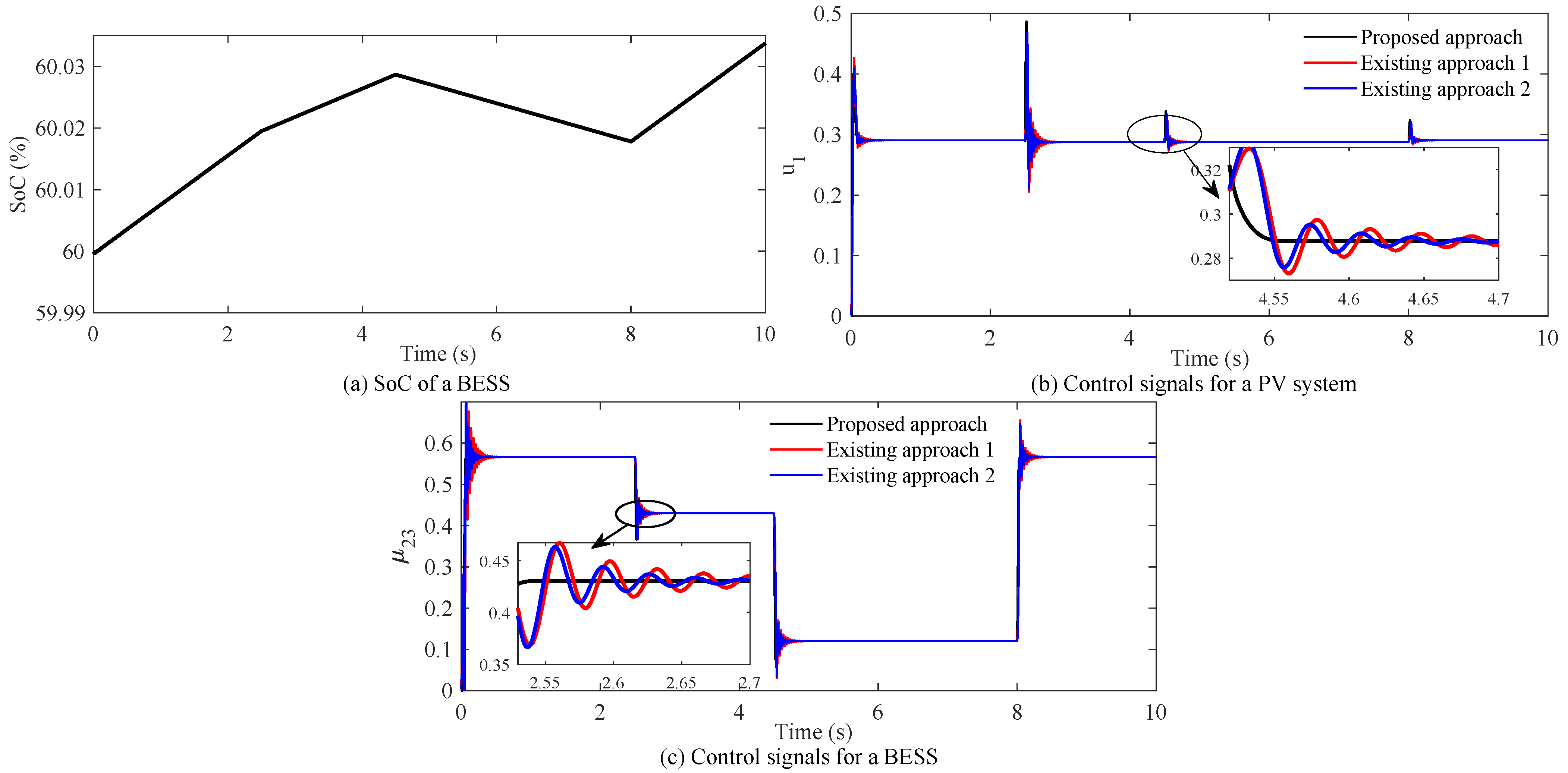
Again, at t = 4.5 s, the output power generated by the solar PV unit changes to 9.335 kW from 7.26 kW owing to atmospheric fluctuations. At the same time, the load demand increases from 3.122 kW to 11.6 kW as illustrated in
Figure 5b. During this time interval, the total load demand is greater than the total generation, and to supply this shortage power, the BESS discharges its power (2.596 kW), which can be seen in
Figure 5c. The corresponding
of the BESS is shown in
Figure 6a. The abrupt increase in load demand results in a rapid decrease in DC-bus voltage, as seen in
Figure 5d. Again, at t = 8 s, the load demand reduces back to 3.13 kW from 11.6 kW at the same time the solar PV unit changes to 10.34 kW from 9.335 kW. During this time interval, the total generation is greater than the total load demand. In this case, the BESS is storing the excess power through the charging mode to maintain power balance while maintaining a steady 120 V DC-bus voltage. According to
Figure 5d, the DC-bus voltage settles its reference value after the transient at 300 ms and 200 ms when the existing control methods are used, whereas the proposed control technique does it at 2 ms. Furthermore, the performance of the proposed controller and existing controllers in terms of percentage of overshoot and settling time is recorded, which is demonstrated in
Table 2,
Table 3,
Table 4 and
Table 5.
As the DCMG’s operating point is being changed many times over the simulation, there are large transients in the power responses and the DC-bus voltage response, as seen in
Figure 5. However, in comparison to the existing controller, the proposed control method provides a better dynamic performance and quicker DC-bus voltage regulation.
Figure 6b,c depicts the associated control signals, which indicate that the control signal for the proposed control technique is more stable than the existing control approaches.
7. Conclusions
This work presents a nonlinear integral terminal sliding mode controller (ITSMC) based on a modified reaching law to enhance the regulation of the DC-bus voltage while maintaining a power balance within a solar PV and BESS-based DCMG. The theoretical analysis and stability of the system with the designed scheme are verified using the control Lyapunov function. Moreover, it is proved that the reaching time of the proposed reaching law is lower than the conventional reaching time for the same gain value. Finally, various operating circumstances, such as changing solar irradiance and load demand, are used to test the efficacy of the designed controller. Based on the simulation results, the finding of this research work can be summarized as follows:
The simulation results clearly indicate that the designed controller can provide faster transient and dynamic stability under a variety of DCMG operational conditions as compared to the existing controllers.
Even with substantial changes in source and load power, the developed controller can follow the reference value of the DC-bus voltage with less overshoot and shorter settling time.
In certain additional ways, the proposed ITSMC outperforms its competitors in terms of implementation robustness, reduced complexity, and chattering-free outputs.
Future studies will examine the DCMG with more than one solar PV units. However, the smooth switching and stability of parallel multi-solar PV converters are critical. Therefore, the next research work will focus on the coordinated control of multi-solar PV converters. Moreover, an adaptive controller will be developed in the future to deal with parametric uncertainties.
Author Contributions
Conceptualization, S.Y., T.K.R. and S.K.G.; methodology, S.Y. and T.K.R.; software, S.Y., T.K.R. and S.K.G.; validation, S.Y. and T.K.R.; formal analysis, S.Y. and T.K.R.; investigation, S.Y. and T.K.R.; Resources, T.K.R. and S.K.G.; writing—original draft preparation, S.Y. and T.K.R.; writing—review and editing, T.K.R. and S.K.G.; supervision, T.K.R.; project administration, T.K.R. and S.K.G. All authors have read and agreed to the current version of the manuscript.
Funding
This research received no external funding.
Institutional Review Board Statement
Not applicable.
Informed Consent Statement
Not applicable.
Data Availability Statement
The data presented in this study are available on request from the corresponding author. The data are not publicly available due to [privacy/ethical restrictions].
Conflicts of Interest
The authors declare no conflict of interest.
Abbreviations
The following abbreviations are used in this manuscript:
| ACMG | AC microgrid |
| BESS | Battery energy storage system |
| BDDC | Bidirectional DC-DC converter |
| BSC | Nonlinear backstepping controller |
| DAB | Dual active bridge |
| DPG | Diesel power generator |
| DDBC | DC-DC boost converter |
| DCMG | DC microgrid |
| FLC | Fuzzy logic controller |
| FBLC | Nonlinear feedback linearization control |
| ITSMC | Integral terminal sliding mode controller |
| ITSS | Modified integral terminal sliding surface |
| MGs | Microgrids |
| MERL | Modified exponential reaching law |
| MPC | Model predictive controller |
| MPPT | Maximum power point tracking |
| RES | Renewable energy source |
| SoC | State of charge |
| SMC | Nonlinear sliding mode control |
| SPV | Solar photovoltaic |
References
- Le, H.T.; Santoso, S.; Nguyen, T.Q. Augmenting Wind Power Penetration and Grid Voltage Stability Limits Using ESS: Application Design, Sizing, and a Case Study. IEEE Trans. Power Syst. 2011, 27, 161–171. [Google Scholar] [CrossRef]
- Ahmad, R.; Mohamed, A.A.A.; Rezk, H.; Al-Dhaifallah, M. DC Energy Hubs for Integration of Community DERs, EVs, and Subway Systems. Sustainability 2022, 14, 1558. [Google Scholar] [CrossRef]
- Roy, T.K.; Mahmud, M.A. Active Power Control of Three-Phase Grid-Connected Solar PV Systems Using a Robust Nonlinear Adaptive Backstepping Approach. Sol. Energy 2017, 153, 64–76. [Google Scholar] [CrossRef]
- Elkhidir, L.; Khan, K.; Al-Muhaini, M.; Khalid, M. Enhancing Transient Response and Voltage Stability of Renewable Integrated Microgrids. Sustainability 2022, 14, 3710. [Google Scholar] [CrossRef]
- Wang, J.; Li, D.; Lv, X.; Meng, X.; Zhang, J.; Ma, T.; Pei, W.; Xiao, H. Two-Stage Energy Management Strategies of Sustainable Wind-PV-Hydrogen-Storage Microgrid Based on Receding Horizon Optimization. Energies 2022, 15, 2861. [Google Scholar] [CrossRef]
- Seyedi, Y.; Karimi, H.; Mahseredjian, J. A Data-Driven Method for Prediction of Post-Fault Voltage Stability in Hybrid AC/DC Microgrids. IEEE Trans. Power Syst. 2022, 1. [Google Scholar] [CrossRef]
- Mohammadi, F. Integration of AC/DC Microgrids into Power Grids. Sustainability 2020, 12, 3313. [Google Scholar] [CrossRef] [Green Version]
- Wahid, A.; Iqbal, J.; Qamar, A.; Ahmed, S.; Basit, A.; Ali, H.; Aldossary, O.M. A Novel Power Scheduling Mechanism for Islanded DC Microgrid Cluster. Sustainability 2020, 12, 6918. [Google Scholar] [CrossRef]
- Ghosh, S.K.; Roy, T.K.; Pramanik, M.A.H.; Sarkar, A.K.; Mahmud, M. An Energy Management System-Based Control Strategy for DC Microgrids with Dual Energy Storage Systems. Energies 2020, 13, 2992. [Google Scholar] [CrossRef]
- Vandoorn, T.L.; Meersman, B.; Degroote, L.; Renders, B.; Vandevelde, L. A Control Strategy for Islanded Microgrids with DC-link Voltage Control. IEEE Trans. Power Deliv. 2011, 26, 703–713. [Google Scholar] [CrossRef]
- Ghosh, S.K.; Roy, T.K.; Pramanik, M.A.H.; Ali, M.S. Energy management techniques to enhance DC-bus voltage transient stability and power balancing issues for islanded DC microgrids. In Advances in Clean Energy Technologies; Elsevier: Amsterdam, The Netherlands, 2021; pp. 349–375. [Google Scholar]
- Hajebrahimi, H.; Kaviri, S.M.; Eren, S.; Bakhshai, A. A New Energy Management Control Method for Energy Storage Systems in Microgrids. IEEE Trans. Power Electron. 2020, 35, 11612–11624. [Google Scholar] [CrossRef]
- Ghosh, S.K.; Roy, T.K.; Pramanik, M.A.H.; Mahmud, M.A. A Nonlinear Double-Integral Sliding Mode Controller Design for Hybrid Energy Storage Systems and Solar Photovoltaic Units to Enhance the Power Management in DC Microgrids. IET Gener. Transm. Distrib. 2022, 16, 2228–2241. [Google Scholar] [CrossRef]
- Som, S.; De, S.; Chakrabarti, S.; Sahoo, S.R.; Ghosh, A. A Robust Controller for Battery Energy Storage System of an Islanded AC Microgrid. IEEE Trans. Ind. Inform. 2021, 18, 207–218. [Google Scholar] [CrossRef]
- Maharjan, L.; Yamagishi, T.; Akagi, H. Active-Power Control of Individual Converter Cells for a Battery Energy Storage System Based on a Multilevel Cascade PWM Converter. IEEE Trans. Power Electron. 2010, 27, 1099–1107. [Google Scholar] [CrossRef]
- Ye, Q.; Mo, R.; Li, H. Low-Frequency Resonance Suppression of a Dual-Active-Bridge DC/DC Converter Enabled DC Microgrid. IEEE J. Emerg. Sel. Top. Power Electron. 2017, 5, 982–994. [Google Scholar] [CrossRef]
- Yang, N.; Paire, D.; Gao, F.; Miraoui, A.; Liu, W. Compensation of Droop Control Using Common Load Condition in DC microgrids to Improve Voltage Regulation and Load Sharing. Int. J. Electr. Power Energy Syst. 2015, 64, 752–760. [Google Scholar] [CrossRef]
- Mohamed, Y.A.R.I.; El-Saadany, E.F. Adaptive Decentralized Droop Controller to Preserve Power Sharing Stability of Paralleled Inverters in Distributed Generation Microgrids. IEEE Trans. Power Electron. 2008, 23, 2806–2816. [Google Scholar] [CrossRef]
- Golsorkhi, M.S.; Savaghebi, M. A Decentralized Control Strategy Based on VI droop for Enhancing Dynamics of Autonomous Hybrid AC/DC Microgrids. IEEE Trans. Power Electron. 2021, 36, 9430–9440. [Google Scholar] [CrossRef]
- Kakigano, H.; Miura, Y.; Ise, T. Distribution Voltage Control for DC Microgrids Using Fuzzy Control and Gain-Scheduling Technique. IEEE Trans. Power Electron. 2012, 28, 2246–2258. [Google Scholar] [CrossRef]
- Vigneysh, T.; Kumarappan, N. Autonomous Operation and Control of Photovoltaic/Solid Oxide Fuel Cell/Battery Energy Storage Based Microgrid Using Fuzzy Logic Controller. Int. J. Hydrogen Energy 2016, 41, 1877–1891. [Google Scholar] [CrossRef]
- Sanchez, S.; Molinas, M. Degree of Influence of System States Transition on the Stability of a DC Microgrid. IEEE Trans. Smart Grid 2014, 5, 2535–2542. [Google Scholar] [CrossRef]
- Lee, J.S.; Choi, Y.J. A Stability Improvement Method of DC Microgrid System Using Passive Damping and Proportional-Resonance (PR) Control. Sustainability 2021, 13, 9542. [Google Scholar] [CrossRef]
- Mardani, M.M.; Khooban, M.H.; Masoudian, A.; Dragičević, T. Model Predictive Control of DC–DC Converters to Mitigate the Effects of Pulsed Power Loads in Naval DC Microgrids. IEEE Trans. Ind. Electron. 2018, 66, 5676–5685. [Google Scholar] [CrossRef] [Green Version]
- Dragičević, T. Dynamic Stabilization of DC Microgrids with Predictive Control of Point-of-Load Converters. IEEE Trans. Power Electron. 2018, 33, 10872–10884. [Google Scholar] [CrossRef] [Green Version]
- Akpolat, A.N.; Habibi, M.R.; Baghaee, H.R.; Dursun, E.; Kuzucuoglu, A.E.E.; Yang, Y.; Dragicevic, T.; Blaabjerg, F. Dynamic Stabilization of DC Microgrids Using ANN-Based Model Predictive Control. IEEE Trans. Energy Convers. 2021, 37, 999–1010. [Google Scholar] [CrossRef]
- Mahmud, M.A.; Roy, T.K.; Islam, S.N.; Saha, S.; Haque, M.E. Nonlinear Decentralized Feedback Linearizing Controller Design for Islanded DC Microgrids. Electr. Power Compon. Syst. 2017, 45, 1747–1761. [Google Scholar] [CrossRef]
- Mahmud, M.A.; Roy, T.K.; Saha, S.; Haque, M.E.; Pota, H.R. Robust Nonlinear Adaptive Feedback Linearizing Decentralized Controller Design for Islanded DC Microgrids. IEEE Trans. Ind. Appl. 2019, 55, 5343–5352. [Google Scholar] [CrossRef]
- Hassan, M.A.; Su, C.L.; Pou, J.; Sulligoi, G.; Almakhles, D.; Bosich, D.; Guerrero, J.M. DC Shipboard Microgrids with Constant Power Loads: A Review of Advanced Nonlinear Control Strategies and Stabilization Techniques. IEEE Trans. Smart Grid 2022, 1. [Google Scholar] [CrossRef]
- Roy, T.K.; Mahmud, M.A. Dynamic Stability Analysis of Hybrid Islanded DC Microgrids Using a Nonlinear Backstepping Approach. IEEE Syst. J. 2017, 12, 3120–3130. [Google Scholar] [CrossRef]
- Roy, T.K.; Mahmud, M.A.; Oo, A.M. Operations of DC microgrids in coordination with AC grids based on nonlinear backstepping controllers. In Proceedings of the 2018 IEEE Power & Energy Society General Meeting (PESGM), Portland, OR, USA, 5–10 August 2018; pp. 1–5. [Google Scholar]
- Roy, T.K.; Mahmud, M.A.; Oo, A.M.T.; Haque, M.E.; Muttaqi, K.M.; Mendis, N. Nonlinear Adaptive Backstepping Controller Design for Islanded DC Microgrids. IEEE Trans. Ind. Appl. 2018, 54, 2857–2873. [Google Scholar] [CrossRef]
- Kumar, V.; Mohanty, S.R.; Kumar, S. Event Trigger Super Twisting Sliding Mode Control for DC Micro Grid with Matched/Unmatched Disturbance Observer. IEEE Trans. Smart Grid 2020, 11, 3837–3849. [Google Scholar] [CrossRef]
- Roy, T.K.; Mahmud, M.A.; Nasiruzzaman, A.; Barik, M.A.; Oo, A.M.T. A Non-Singular Fast Terminal Sliding Mode Control Scheme for Residual Current Compensation Inverters in Compensated Distribution Networks to Mitigate Powerline Bushfires. IET Gener. Transm. Distrib. 2021, 15, 1421–1434. [Google Scholar] [CrossRef]
- Liang, C.; Zhang, Y.; Ji, X.; Meng, X.; An, Y.; Yao, Q. DC bus voltage sliding-mode control for a DC microgrid based on linearized feedback. In Proceedings of the 2019 Chinese Automation Congress (CAC), Hangzhou, China, 22–24 November 2019; pp. 5380–5384. [Google Scholar]
- Esmaeli, A. Stability Analysis and Control of Microgrids by Sliding Mode Control (Retraction of Vol 78, Pg 22, 2016); Elsevier: Amsterdam, The Netherlands, 2017. [Google Scholar]
- Kalla, U.K.; Singh, B.; Murthy, S.S.; Jain, C.; Kant, K. Adaptive Sliding Mode Control of Standalone Single-Phase Microgrid Using Hydro, Wind, and Solar PV Array-Based Generation. IEEE Trans. Smart Grid 2017, 9, 6806–6814. [Google Scholar] [CrossRef]
- Chaturvedi, S.; Fulwani, D.; Guerrero, J.M. Adaptive-SMC Based Output Impedance Shaping in DC Microgrids Affected by Inverter Loads. IEEE Trans. Sustain. Energy 2020, 11, 2940–2949. [Google Scholar] [CrossRef]
- Gudey, S.K.; Gupta, R. Recursive Fast Terminal Sliding Mode Control in Voltage Source Inverter for a Low-Voltage Microgrid System. IET Gener. Transm. Distrib. 2016, 10, 1536–1543. [Google Scholar] [CrossRef]
- Roy, T.K.; Mahmud, M.A. Fault Current Compensations in Resonant Grounded Distribution Systems to Mitigate Powerline Bushfires Using a Nonsingular Terminal Sliding Model Controller. IET Gener. Transm. Distrib. 2022, 16, 479–491. [Google Scholar] [CrossRef]
| Publisher’s Note: MDPI stays neutral with regard to jurisdictional claims in published maps and institutional affiliations. |
© 2022 by the authors. Licensee MDPI, Basel, Switzerland. This article is an open access article distributed under the terms and conditions of the Creative Commons Attribution (CC BY) license (https://creativecommons.org/licenses/by/4.0/).


