Article

Novel Axial Flux-Switching Permanent Magnet Machine for High-Speed Applications

School of the Electrical Engineering, Southeast University, Nanjing 210096, China
*
Author to whom correspondence should be addressed.
Sustainability 2022, 14(13), 7774; https://doi.org/10.3390/su14137774
Submission received: 23 May 2022 / Revised: 21 June 2022 / Accepted: 24 June 2022 / Published: 25 June 2022
(This article belongs to the Special Issue Intelligence and Sustainability in Electrical Engineering)

Abstract

:
Conventional high-speed flux-switching machines have either a high fundamental frequency or more even harmonics. This paper proposes a novel six-slot four-pole axial flux-switching permanent magnet machine for high-speed applications. The machine, consisting of two radially distributed stators and one rotor, can effectively eliminate even harmonics in the flux linkage. First, the structural parameters that affect the performance of the motor are determined by the equivalent magnetic circuit method, and the optimal structural parameters of the motor are obtained by simulation optimization. Then, through finite element analysis, the three-dimensional model of the proposed machine is built, and the static electromagnetic characteristics are analyzed, including magnetic field distribution, flux linkage, back-electromotive force, cogging torque, and efficiency. The simulation results show that the total harmonic distortion of the flux linkage and back-electromotive force waveforms of the proposed novel machine is 2.2% and 9.8% respectively. The cogging torque of the optimal model is only 9 N.

1. Introduction

In recent years, the high-speed motor has been extensively investigated in academia to achieve higher power densities. Compared with traditional electric excitation machines, the permanent magnet (PM) motor has the advantages of small size, high efficiency, and flexible shape and size [1,2]. However, most PM machines take the risks of irreversible demagnetization and mechanical instability at high speed, because the PMs are placed on the rotor [3]. Therefore, a new hybrid structure of the rotor was proposed to improve the mechanical instability [4]. Meanwhile, high-mechanical-strength amorphous metal was used to replace the silicon steel sheet of the interior PM rotor [5]. Although these methods can enhance the mechanical strength of the rotor, they do not completely solve the risks faced by the permanent magnet in the high-speed operation of the rotor. Consequently, the flux-switching permanent magnet (FSPM) machine was proposed with its unique features such as PM stator structure and robust rotor structure [6].
FSPM machines not only combine the advantages of the PM stator structure and modular stator, but also have a relatively sinusoidal bipolar flux linkage, which can increase the back-EMF constant and output torque [7,8]. The combinations of slot and pole numbers in the FSPM machines were compared in [9], which showed that the larger torque can be obtained by the machine with a higher rotor pole number. As described in [10], when the number of stator slots is 6, the greater the least common multiple of stator slots and rotor poles, the smaller the cogging torque. However, the 6-slot/11-pole (6/11) machine has a more symmetrical and sinusoidal flux linkage. Although there are many new FSPM machine topologies and different stator slot/rotor pole combinations developed in the literature, the research has primarily focused on 10-pole or higher-pole FSPM machines [11]. The higher fundamental frequency caused by those machines is a new challenge for high-speed FSPM machines. Thus, low-pole FSPM machines need more attention.
As we all know, when the speed is constant, the higher the number of rotor poles of the FSPM machine, the higher the fundamental frequency. Meanwhile, a higher frequency of magnetic flux conversion produces higher losses, thus reducing the efficiency of the motor. Therefore, the loss of the 12-slot/10-pole (12/10) FSPM machine was analyzed in detail by fast Fourier transformation (FFT). The simulation results showed that the eddy current loss in the magnetic flux can be effectively reduced by using axial magnet segmentation [12]. Additionally, some researchers have tried to adopt low rotor pole number configurations of 6-slot/4-pole (6/4) and 6-slot/5-pole (6/5) in FSPM machines. The investigation of the conventional 6/4 topology showed that the inherent even harmonics of the flux linkage of the FSPM machine will increase the output torque ripple. To eliminate even harmonics, a novel dual-stator 6/4 radial FSPM machine was proposed in [13], and the principle of eliminating even harmonics in the flux linkage was introduced in detail. In [14], a prototype dual-stator 6/4 FSPM machine was built and tested on a dynamometer. The experimental results verified the correctness of the theoretical analysis. Based on the axial dual-stator FSPM machine, a fractional slot distributed winding was introduced in [15]. Compared with the other winding forms, the FSPM machine with a fractional slot distributed winding has a higher winding factor and torque density.
However, compared with the axial FSPM machine, the radial FSPM machine has a longer axial length, which affects the use of the machine in a narrow space such as an electric vehicle. Therefore, a novel 6/4 dual-rotor single-stator axial FSPM was presented [16]. The rotor and stator were distributed along the axial direction, and the stator was located between the two rotors. In addition, the principle of eliminating even harmonics was introduced in [17], and a dual-stator single-rotor axial FPSM machine can also eliminate even harmonics. At present, the arrangement of the dual-stator or dual-rotor is along the axial direction in existing papers. More investigations are needed to focus on a dual-stator placed radially.
The contribution of this paper is to propose a novel 6/4 dual-stator axial FSPM machine to eliminate the even second harmonic in the flux linkage. The advantages consist of shorter axial length, lower base frequency, and high efficiency, as shown in Table 1. The topology of the proposed FSPM and the principle of cancellation of even-order harmonics are introduced in Section 2. In Section 3, the equivalent magnetic circuit model of the 6/4 FSPM machine is established, through the equivalent magnetic circuit method. The optimal structural parameters of the proposed motor are determined through the optimization analysis. Section 4 discusses the results of the electromagnetic performance analyzed by 3-D FEM.

2. Design Evaluation of Proposed 6/4 FSPM Machines

It is an inherent issue for the conventional 6/4 FSPM machine to produce the even-order harmonics, which makes the back-EMF waveform exhibit severe harmonic distortion [18], which makes the machine unusable. Moreover, the angle between two flux linkages of the same phase is the main reason for generating even-order harmonics. There are two mutually independent windings in the proposed 6/4 axial FSPM machine. The topology of the machine only includes two stators and one rotor.

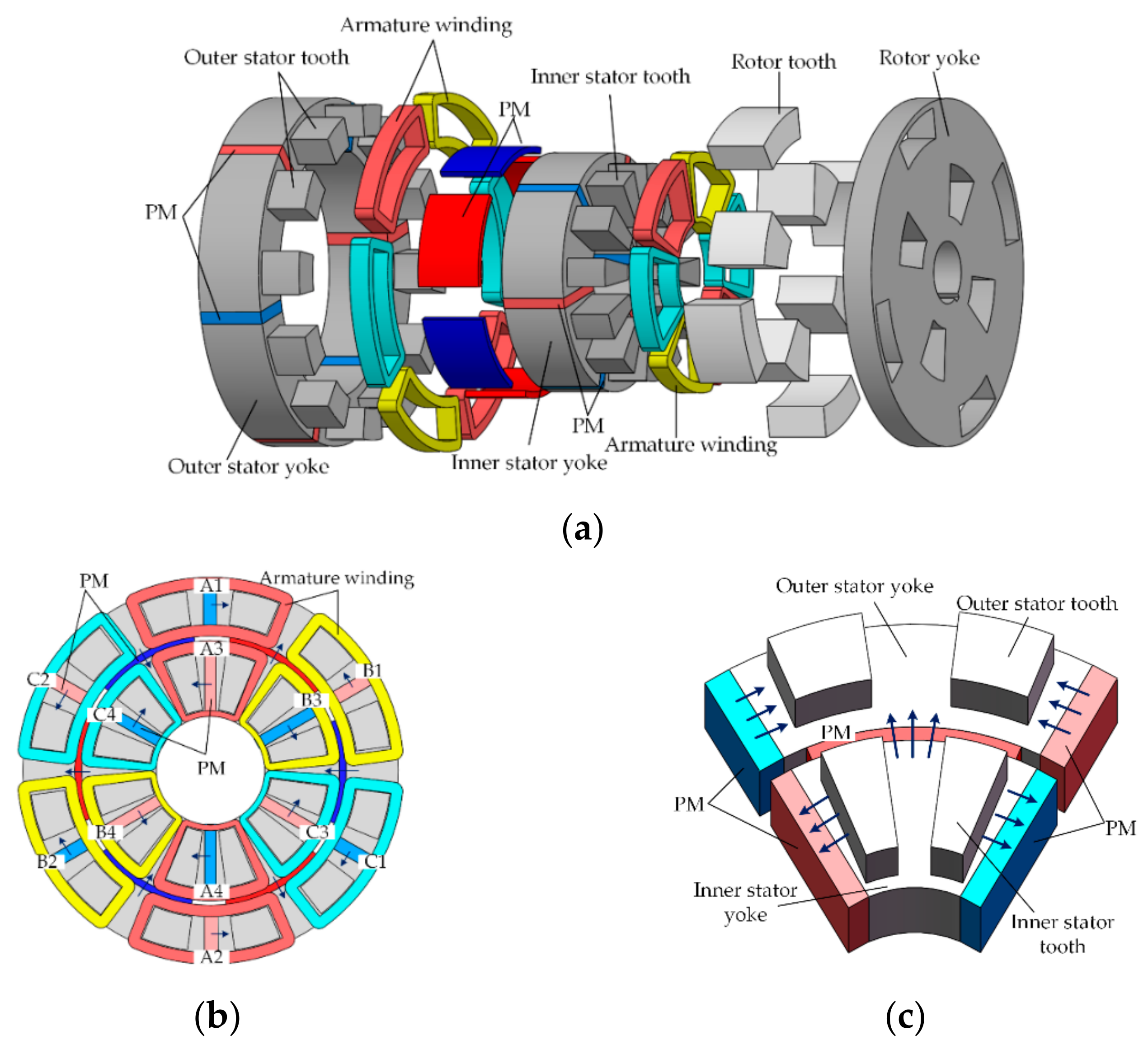
2.1. Fundamental Configuration

The 3-D topology of the proposed AxFSPM machine is shown in Figure 1, which has an innovative stator construction and nonmagnetic rotor. The stator consists of radially distributed inner and outer stators and PMs. The stator cores, circumferential magnetized permanent magnets, and centralized windings of the inner and outer stators are installed in the same way as that of traditional flux switching motors. The difference is that the stator core consists of an I-shaped yoke and two teeth, which are stacked axially and radially, respectively. Meanwhile, six radially magnetized PMs are arranged between the inner and outer stator cores. Unlike the stator, the rotor is a disc structure with eight rotor poles, which can be divided into inner rotor teeth and outer rotor teeth. The angle between the inner and outer rotor teeth can be adjusted according to performance requirements. In order to enhance the structural strength of the rotor and facilitate the machining, the rotor back iron adopts the axial stacking mode and the rotor teeth are embedded in the groove.
Figure 1b shows the distribution of the three-phase windings on the stator. It can be seen that the coils are divided into phases A, B, and C in the clockwise direction. Four coils of the same color are connected to form a phase. Taking phase A as an example, in order to obtain the same induced electromotive force, outer winding coils A1 and A2 are wound in opposite directions to inner winding coils A3 and A4. The assembly of the inner stator and outer stator core and permanent magnets is shown in Figure 1c. The magnetization directions are illustrated by arrows. Three permanent magnets have the same polarity on the contact surface with the stator core.

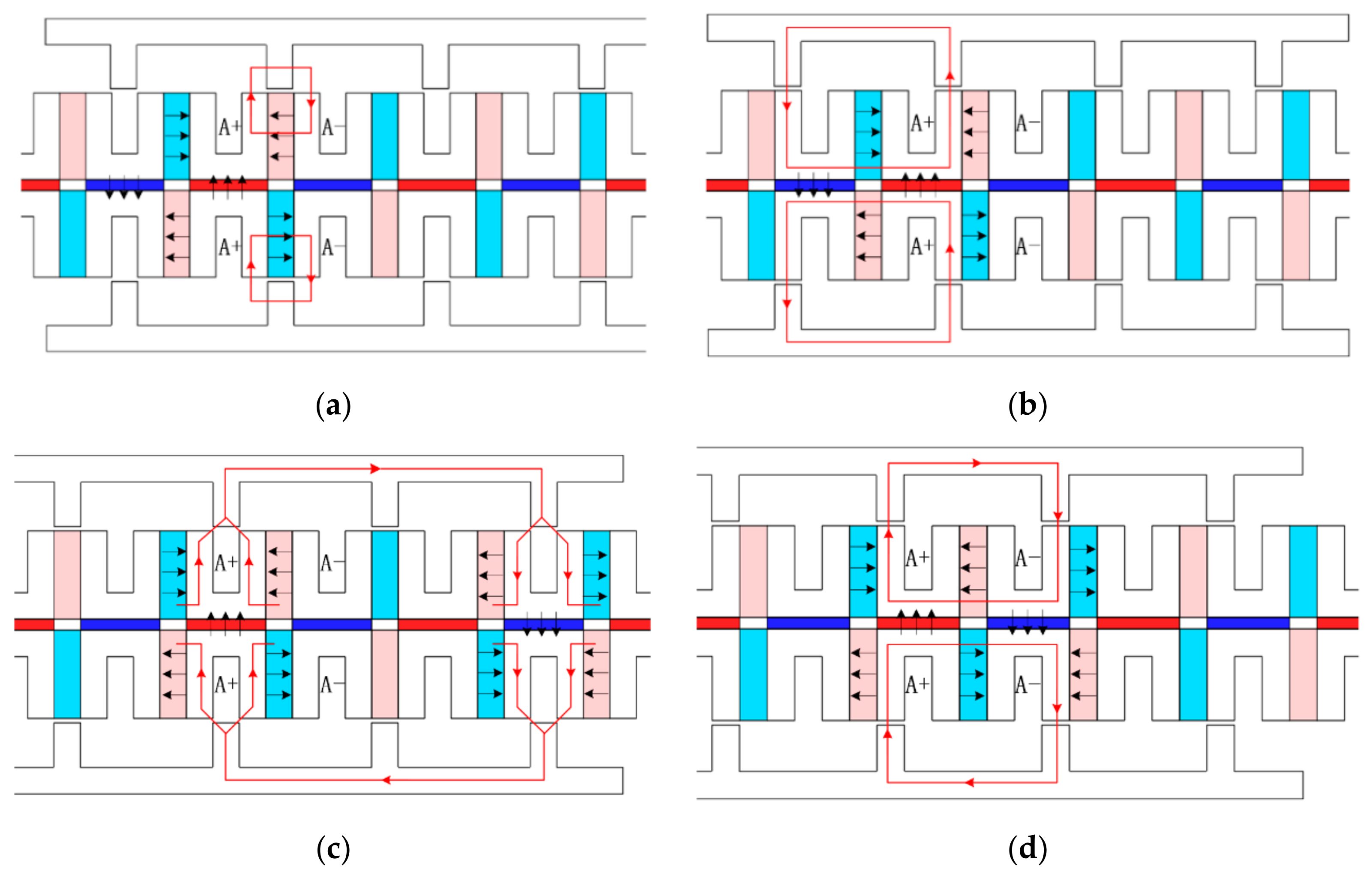
2.2. Operation Principle

To facilitate the understanding, the 6/4 AxFSPM machine is equivalent to a 2-D linear motor structure. Figure 2 shows the alternating magnetic flux path variation of the 6/4 FSPM within half an electric angle period. Four typical positions including the initial position, 1/6 electric cycle, 1/3 electric cycle, and half an electric cycle are displayed, respectively, from Figure 2a to Figure 2d. At the initial position, the rotor pole is aligned with the PM, which is wound by the phase A coil. As the two stator teeth wound by the phase A coil have the same and opposite magnetic flux, the total flux linkage of phase A is zero. When the rotor moves to the 1/6 electric cycle, the flux linkage of phase A reaches its maximum. As the rotor moves from the 1/6 electric cycle to the 1/2 electric cycle, the flux linkage of phase A decreases to zero.
It can be seen from the above phenomenon that the magnetic flux of the 6/4 FSPM machine does not change from sinusoidal in an electric cycle. Large-even-order harmonics are the main reason for this problem. Figure 3 shows the flux linkage of phase A. The Fast Fourier Transformation (FFT) of the flux linkage of phase A is shown in Figure 3b. It reveals that a significant amount of even-order harmonics exists in the flux linkage, and the proportion of the second harmonic in the fundamental wave reaches 60%.

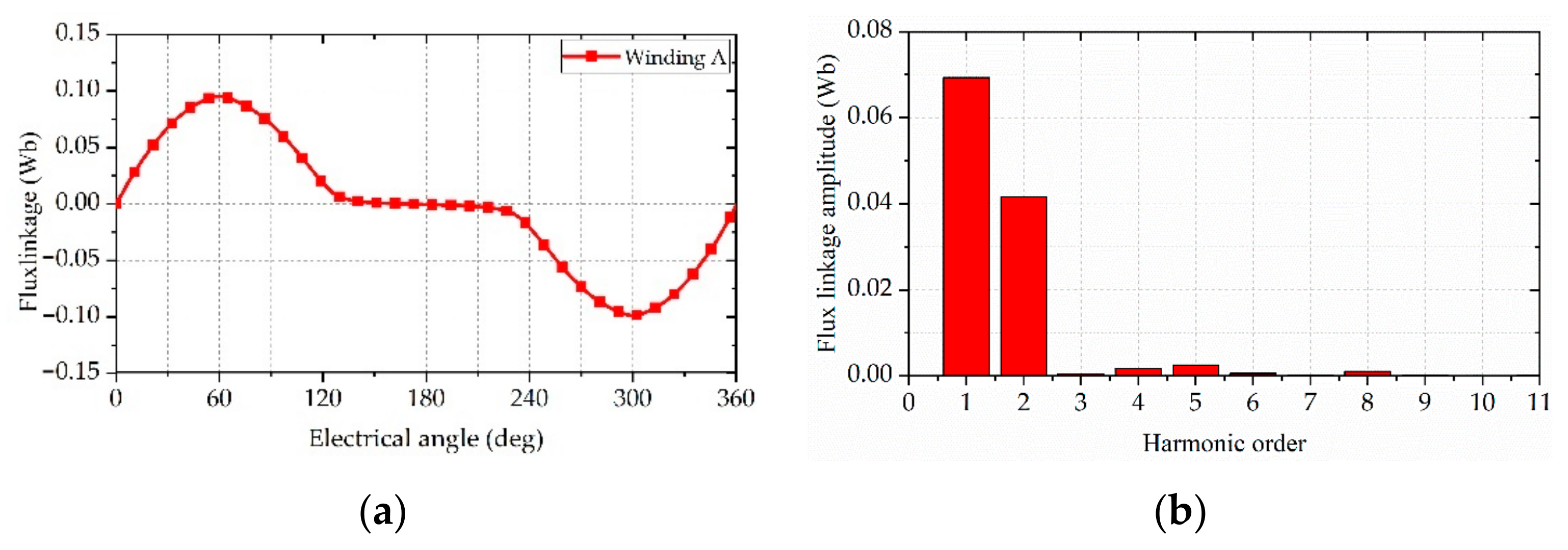
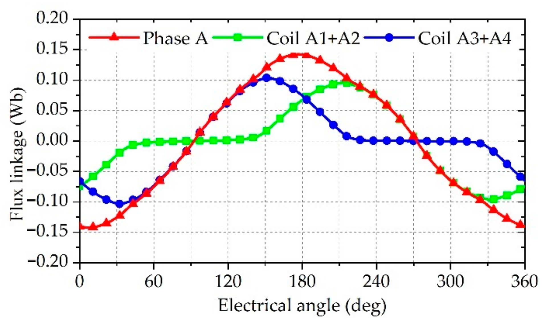
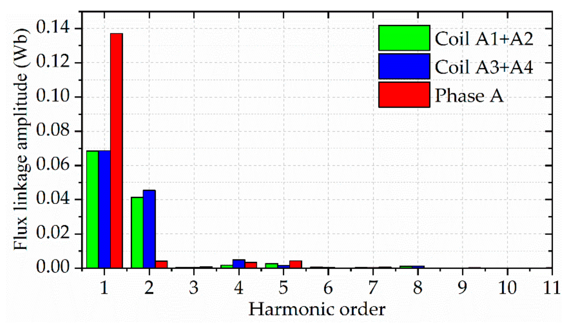
2.3. Even Harmonic Cancellation

Even-order harmonics of the flux linkage have a bad effect on the operation of the 6/4 FSPM machine. Therefore, to eliminate even harmonics, the proposed 6/4 AxFSPM machine adopts two sets of radial distribution disk stators. Meanwhile, the flux linkage of each phase winding is obtained from the winding coils on the inner and outer stators, in the proposed 6/4 AxFSPM machine. According to the above analysis, the A-phase winding flux located in the inner and outer stator can be obtained, respectively [13].
ψ A 1 + A 2 = N = 1 , 3 , 5 , Ψ N sin ( N p r θ e ) + N = 2 , 4 , 6 , Ψ N sin ( N p r θ e )
ψ A 3 + A 4 = N = 1 , 3 , 5 , Ψ N sin ( N p r θ e + N θ N ) N = 2 , 4 , 6 , Ψ N sin ( N p r θ e + N θ N )
where N is the number of harmonics, Ψ N is the amplitude of N -order harmonics of the flux linkage, p r is the number of rotor poles, θ e is the mechanical angle, and θ N is the initial electric angle between the inner and outer stator flux linkage.
Because the magnetization direction of a PM wound by coil A3 is opposite to that wound by coil A1, the flux linkage of coil A3 is negative. Therefore, the total flux linkage of the A phase can be synthesized by Equations (1) and (2).
ψ A = N = 1 , 3 , 5 , Ψ N sin ( N p r θ e ) + N = 2 , 4 , 6 , Ψ N sin ( N p r θ e ) N = 1 , 3 , 5 , Ψ N sin ( N p r θ e + N θ N ) N = 2 , 4 , 6 , Ψ N sin ( N p r θ e + N θ N )
It can be observed from Equation (3) that the even harmonic can be eliminated by varying the initial electric angle θ N . When θ N is equal to ± π , Equation (3) can be simplified as
ψ A = N = 1 , 3 , 5 , 2 Ψ N sin ( N p r θ e )
According to the derivation of the above formula, even harmonics can be effectively suppressed by using the dislocation of inner and outer stator windings. As shown in Figure 4, through the superposition of internal and external stator windings, the flux linkage waveform of phase A winding is close to sinusoidal. However, due to the inner and outer distribution of the double stators of the proposed FSPM machine in this paper, the proportion of even harmonics contained in the winding flux is different, as shown in Figure 5. Therefore, it is necessary to eliminate even harmonics by changing other machine parameters such as winding turns and magnetization area.

3. Analytical Calculation of Proposed 6/4 FSPM Machine

At present, 3D FEA is mostly used in the simulation of a disc machine [19]. This method can calculate the more accurate electromagnetic performance of the motor through fine subdivision, but it takes a long time. Thus, it is not conducive to the optimal simulation speed of the motor. Additionally, FEA cannot obtain the influence of each size parameter of the motor on the performance, which increa5ses the difficulty of modifying each parameter of the motor. Therefore, this paper establishes the magnetic equivalent circuit (MEC) model of the disc motor to obtain the influence of each parameter on the performance.

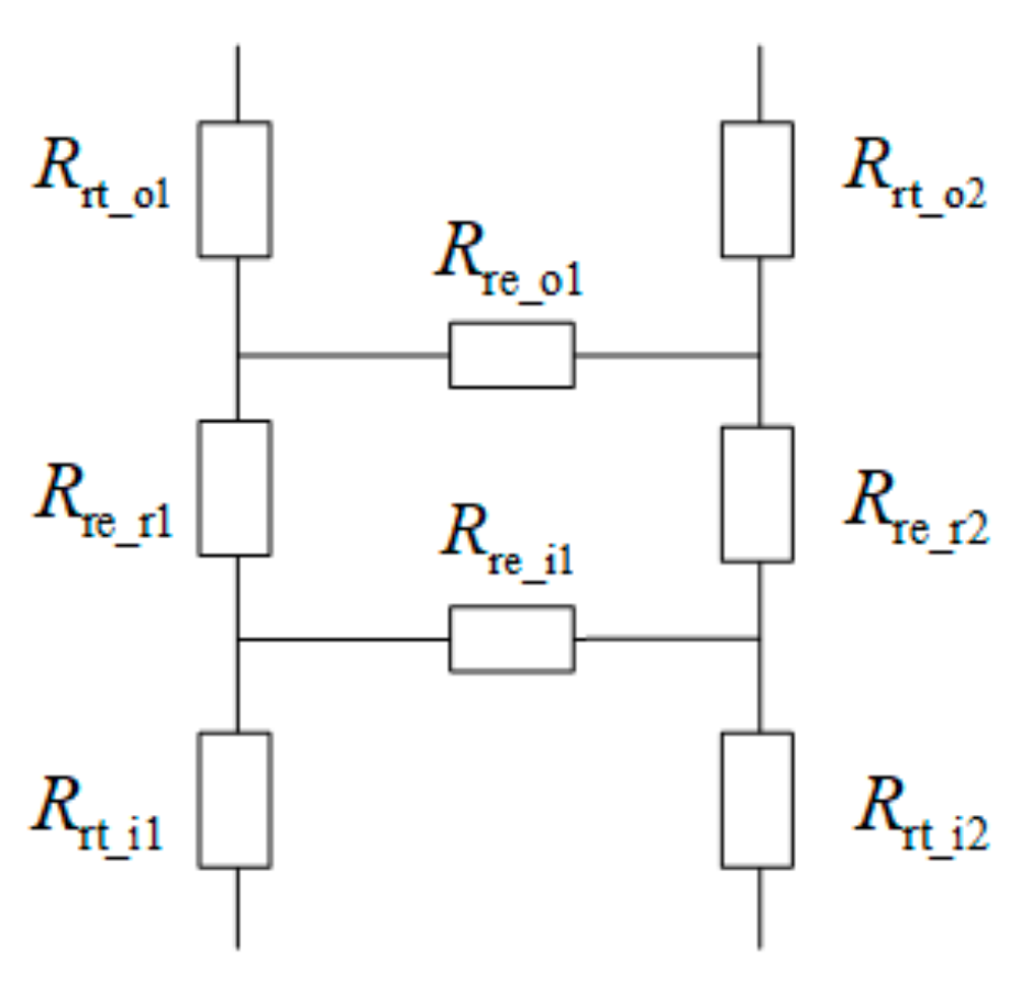
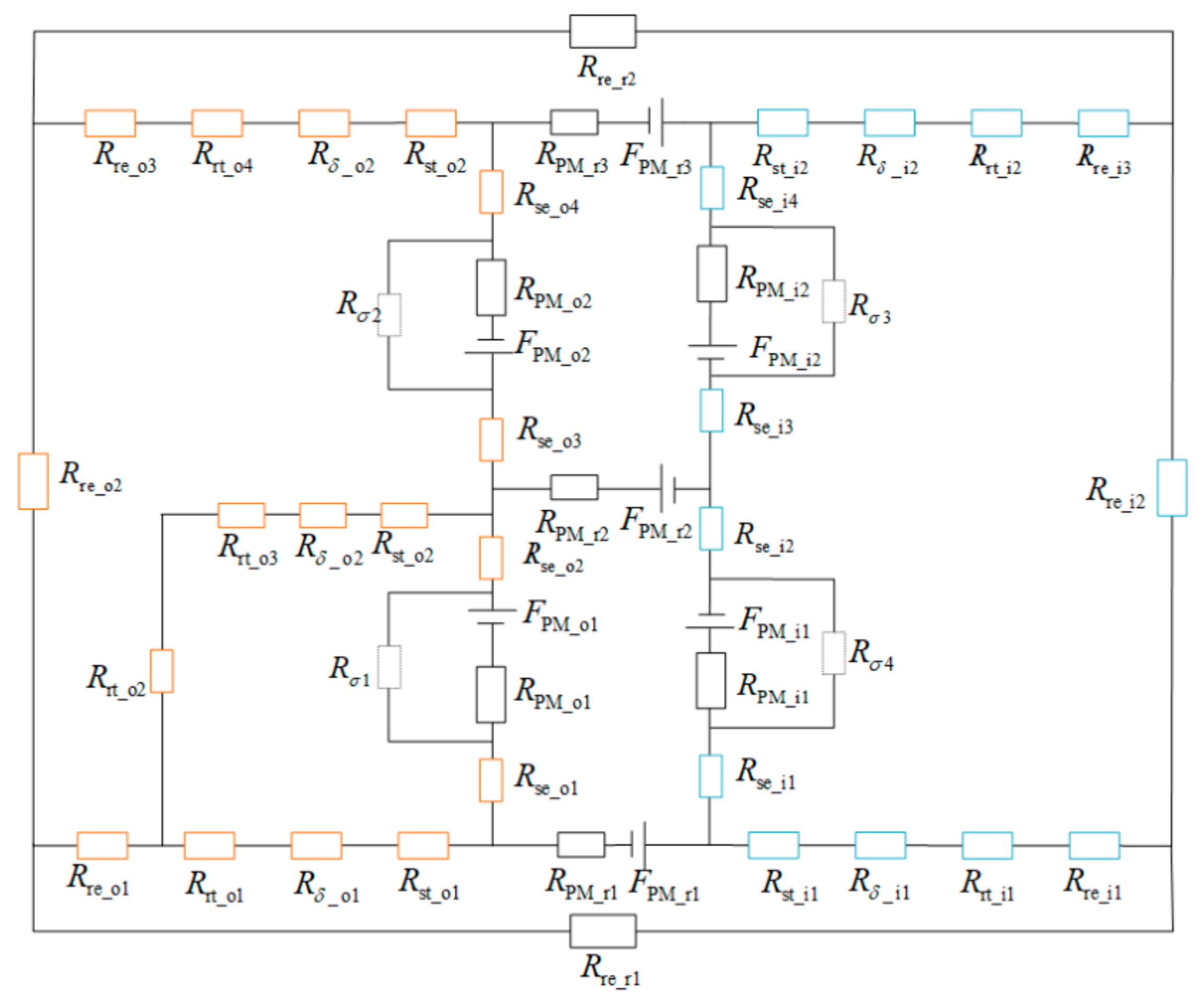
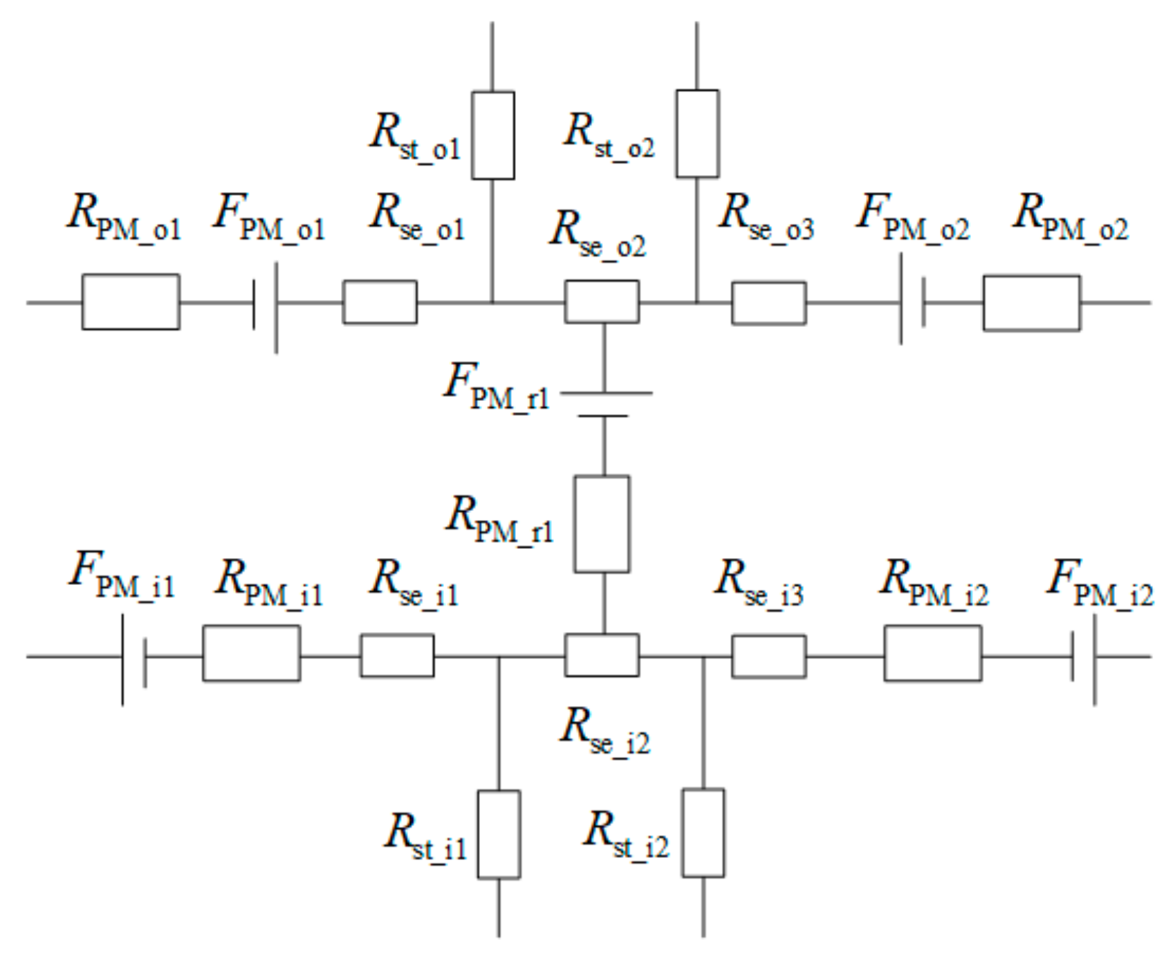
3.1. Magnetic Circuit Analysis

The main magnetic circuit of the new disc motor is complex, including a radial magnetic circuit, axial magnetic circuit, and circumferential magnetic circuit. Therefore, the stator part and the rotor part need to be simplified. According to the structure diagram of a single stator core module shown in Figure 1c, the equivalent magnetic circuit model of a single stator module can be deduced, as shown in Figure 6.
F PM _ o 1 and F PM _ o 2 are the PM-equivalent magnetomotive forces (MMFs) in the outer stator. R PM _ o 1 and R PM _ o 2 are the PM-equivalent internal reluctances. R st _ o 1 and R st _ o 2 are the equivalent reluctances of an outer stator tooth. R se _ o 1 ~ R se _ o 3 are the equivalent reluctances of an outer stator yoke. F PM _ r 1 is the radial magnetized PM-equivalent MMF. R PM _ r 1 is the radial magnetized PM-equivalent reluctance. F PM _ i 1 and F PM _ i 2 are the PM-equivalent magnetomotive forces (MMFs) in the inner stator. R PM _ i 1 and R PM _ i 2 are the PM-equivalent internal reluctances. R st _ i 1 and R st _ i 2 are the equivalent reluctances of an inner stator tooth. R se _ i 1 ~ R se _ i 3 are the equivalent reluctances of an inner stator yoke.
Figure 7 shows the equivalent magnetic circuit diagram of the rotor. It can be seen from the figure that the transmission of magnetic flux between the inner and outer rotor teeth is a form of parallel connection. R rt _ o 1 and R rt _ o 2 are the equivalent reluctances of an outer rotor tooth. R re _ o 1 , R re _ r 1 , R re _ r 2 , and R re _ i 1 are the equivalent reluctances of a rotor yoke. R rt _ i 1 and R rt _ i 2 are the equivalent reluctances of an inner rotor tooth.
Figure 8 shows the two different flux paths in the motor. The red dotted line with an arrow indicates the direction of the magnetic flux. For the calculation of the reluctance of the motor stator and rotor yoke, it is equivalent to the conventional cube shape, as shown in Figure 8a, and the calculation formula can be expressed as
R c u b = L a μ 0 μ s S a
where S a is the cross-sectional area of the magnetic flux path. L a is the path length of magnetic flux. μ 0 is the permeability of vacuum. μ s is the relative permeability.
In the stator and rotor teeth of the motor, the direction of the magnetic flux will change. Therefore, during calculation of the reluctance, it is necessary to follow the shape shown in Figure 8b, and the reluctance formula can be expressed as
R s = π μ 0 μ s L s ln ( 1 + π L t _ e 4 h t )
where L s is the thickness of the stator teeth. L t _ e is the height of the stator yoke. h t is the height of the stator teeth.
For ease of understanding, the MEC model of the 6/4 FSPM machine under a pair of magnetic poles at 1/6 electric angle is given, as shown in Figure 9. The yellow rectangle represents the reluctance of the outer stator and outer rotor. The blue rectangle represents the inner stator and inner rotor. R σ 1 , R σ 2 , R σ 3 , and R σ 4 are the magnetic flux leakage reluctances between the adjacent stator yokes.
According to Kirchhoff’s law of magnetic circuits, the corresponding magnetic circuit equation is given by [20]
F m = Φ m R all
where F m is the MMF, Φ m is the main magnetic flux, and R all is the total magnetic reluctance in the magnetic circuit.
The MMF and magnetic flux of a PM can be given by [20]
F m = H c w PM
Φ m = B r S PM
where H c , w PM , B r , and S PM are the intrinsic coercivity, thickness, remanence, and magnetization area of the PM, respectively.
According to the change in magnetic flux of each phase winding, the back-EMF of phase A can be obtained:
E A = N A ω Φ A 2
where N A is the number of turns of phase A, ω is the angular frequency, and Φ A is the magnetic flux passing through phase A.
The harmonic amplitude can be obtained by Fourier decomposition of the back-EMF. Therefore, the total harmonic distortion (THD) of the back-EMF can be expressed as
T H D = ( U 2 2 + U 3 2 + + U n 2 ) U 1 2
where U 1 is the amplitude of the fundamental back-EMF and U n is the nth harmonic amplitude of the back-EMF.
Figure 10 shows the comparison results of flux linkage between the magnetic circuit model and FEA in the no-load case. The magnetic linkage calculated by the equivalent magnetic circuit method is obviously larger than that obtained by FEA. This is mainly because the saturation is not considered in the equivalent magnetic circuit. In addition, the sine of the flux waveform is poor, so it is necessary to reduce the harmonic content in the waveform through parameter optimization.

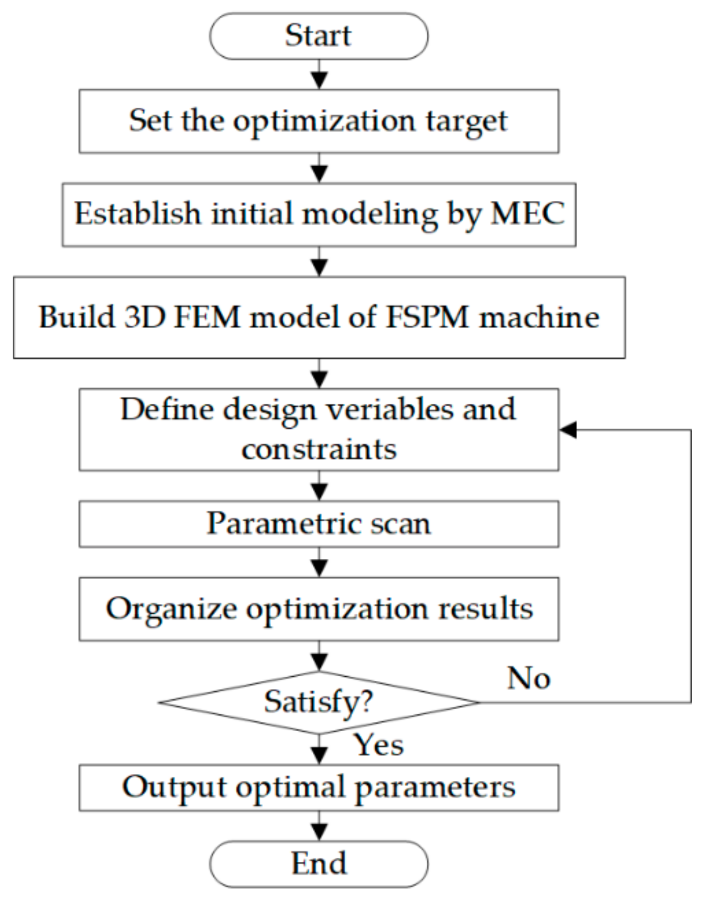
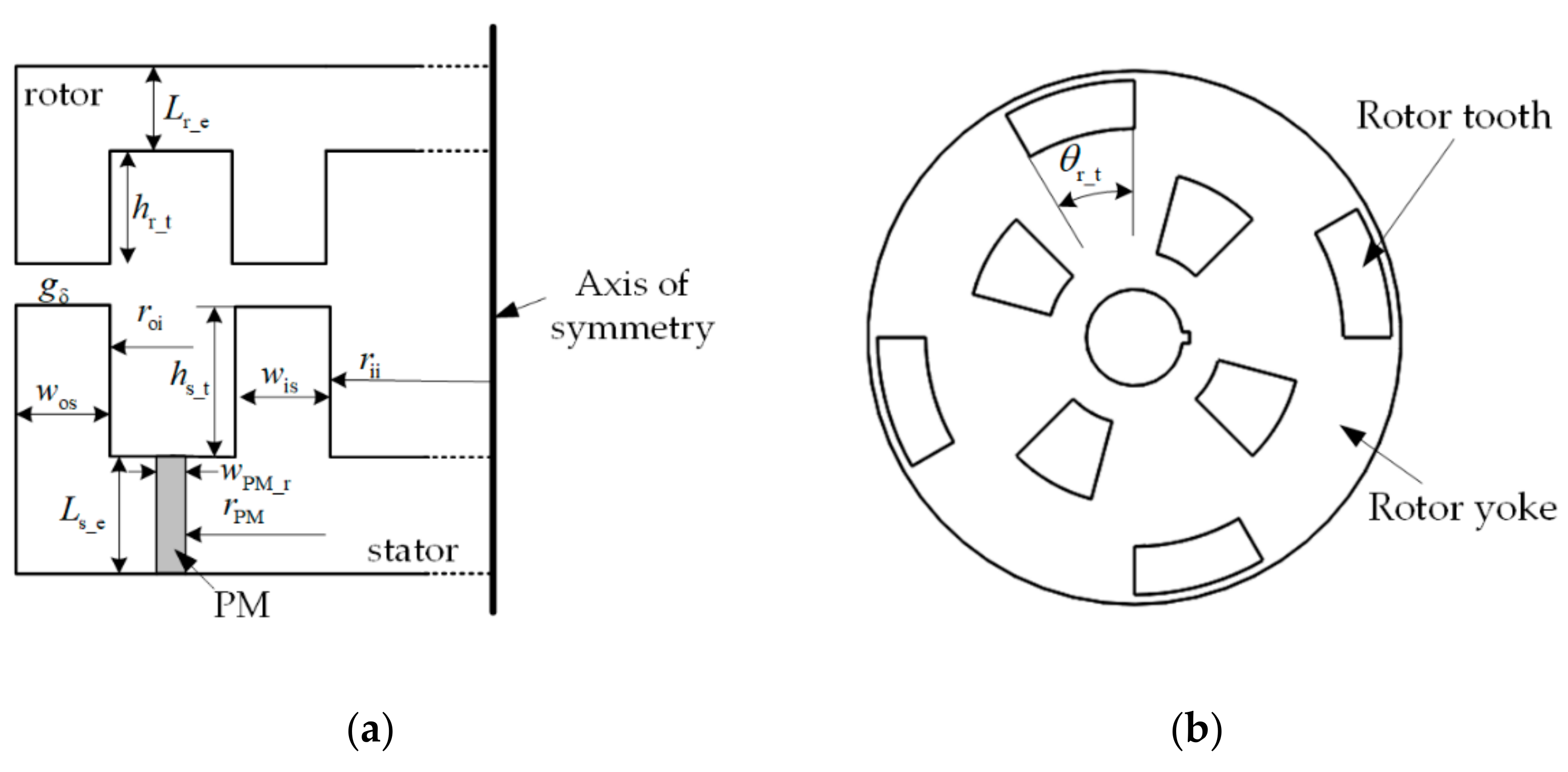
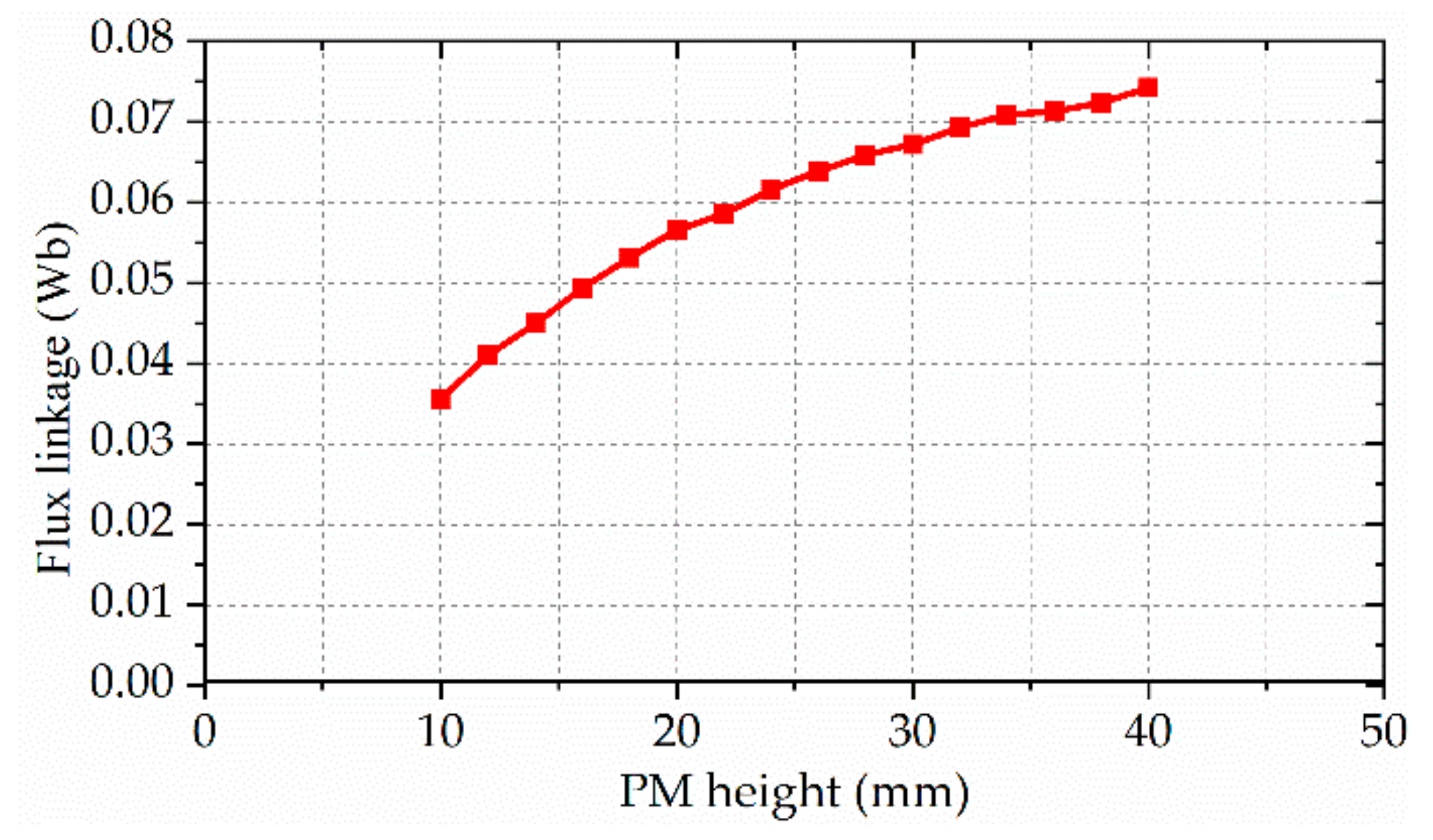
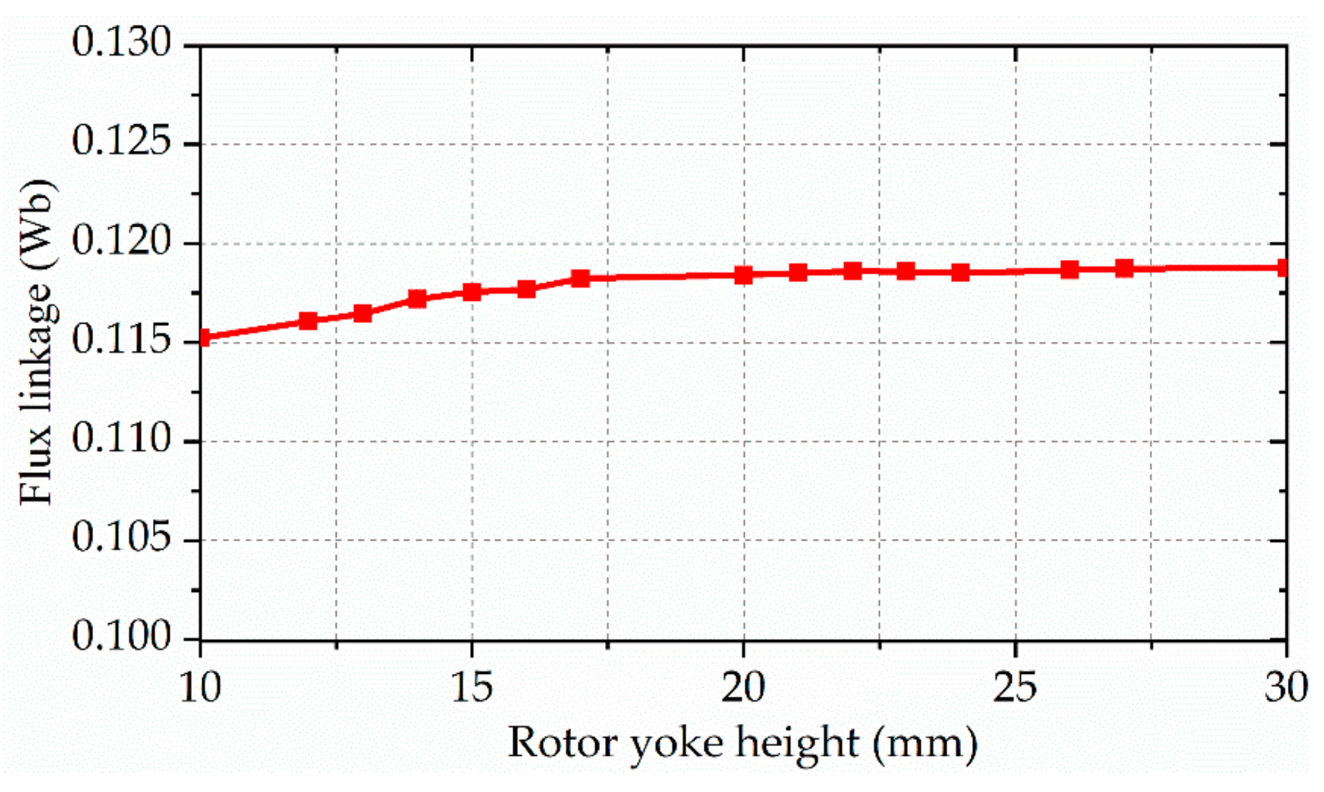
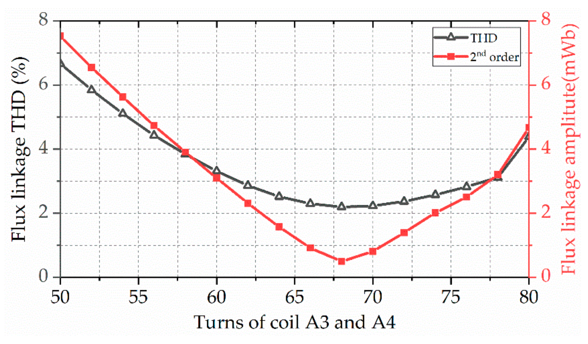
3.2. Parameter Optimization

In the previous section, the MEC model of the new machine is introduced. The dimension parameters that have a great impact on the performance of the motor are obtained. In this section, parametric scanning is used to calculate the optimal performance. The flow chart of the optimization process is shown in Figure 11. According to the design requirements, the rated power of the FSPM machine is 7.5 kW, the rated speed is 3000 rpm, and the efficiency is greater than 85%. Therefore, to meet the design requirements, the optimization objectives of machine performance are set, and the initial model is obtained by the MEC method. Then, the 3D finite element model is established, and the parameter variables and constraints are determined. Finally, the results satisfying the optimization objectives are obtained by means of parametric scanning.
Therefore, three performance variables, including THD of the flux linkage F THD , cogging torque T cog , and output torque T e , are set as optimization objectives. The objective function of optimization can be obtained as follows:
F THD < 5 % ;   T cog < 5 N max : T e
To improve the stability of the machine operation, the optimization results need to satisfy F THD < 5 % ;   T cog < 5 N . Then, the model with the largest output torque is selected.
The main design variables with their allowable range are listed in Table 2 and the dimension parameters of the 6/4 FSPM machine are shown in Figure 12. As the inner and outer stator teeth have the same angle, in order to ensure equal areas of the inner and outer stator teeth, the width of the outer stator teeth should be less than that of the inner stator teeth. The two structure constraints must be strictly observed during the design process. Those constraints are given as follows:
  r all 300 mm L all 100 mm
where r all is the outer diameter of the motor and L all is the axial length of the motor.
As the main source of magnetic field, the size of the permanent magnet has a great impact on the performance of the motor. According to Equation (9), the larger the area of the permanent magnet is, the greater the magnetic flux is. Because the proposed machine has a variety of magnetic circuits, 3D FEA is used to calculate the influence of different structural dimensions on the performance of the motor.
In order to study the influence of the height of the permanent magnet on the saturation of the stator tooth magnetic field, the height of the stator yoke and the rotor yoke is designed to be equal to the height of the permanent magnet. As shown in Figure 13, with the increase in the height of the permanent magnet, the magnetic linkage amplitudes of coils A1 and A2 also increase gradually. At the same time, due to the magnetic field saturation of the stator tooth, the increase in the magnetic linkage decreases gradually. Therefore, the height of the permanent magnet is selected as 28 mm.
According to Equation (6), the height of the rotor yoke affects the reluctance of the main magnetic circuit, adjusting the performance of the machine. Figure 14 shows the influence of rotor yoke height on magnetic linkage amplitudes of phase A. It can be seen that the increase in rotor yoke height leads to the increase in flux linkage, but the increase in flux linkage gradually slows down. This is mainly because the saturation degree of the rotor magnetic circuit decreases with the increase in rotor yoke height. When the height of the rotor yoke exceeds 17 mm, the increase in flux linkage amplitude can be ignored. Therefore, in order to reduce the cost and the quality of the rotor, the yoke height of the rotor is set to 17 mm.
The flux switching motor proposed in this paper adopts a double stator radial distribution, which leads to the difference between the inner stator slot width and the outer stator slot width. Therefore, the amplitude of the second harmonic contained in the outer stator winding is different from that of the inner stator winding, so the second harmonic cannot be eliminated. This problem can be solved by adjusting the number of turns of internal external windings. The inner and outer coils of phase A are scanned parametrically with different turns, and the results are shown in Figure 15. It can be seen that when the number of turns of the outer coil is 50 and the number of turns of the inner coil is 68, the second harmonic of the phase A flux linkage is basically eliminated.
Through the above optimization process, the main parameters of the motor are listed in Table 3.

4. Performance Evaluation

In this section, the electromagnetic characteristics of the proposed 6/4 AxFSPM machine are evaluated by 3D FEA, including magnetic field distribution, flux linkage, back-EMF, cogging torque, output power, and efficiency.

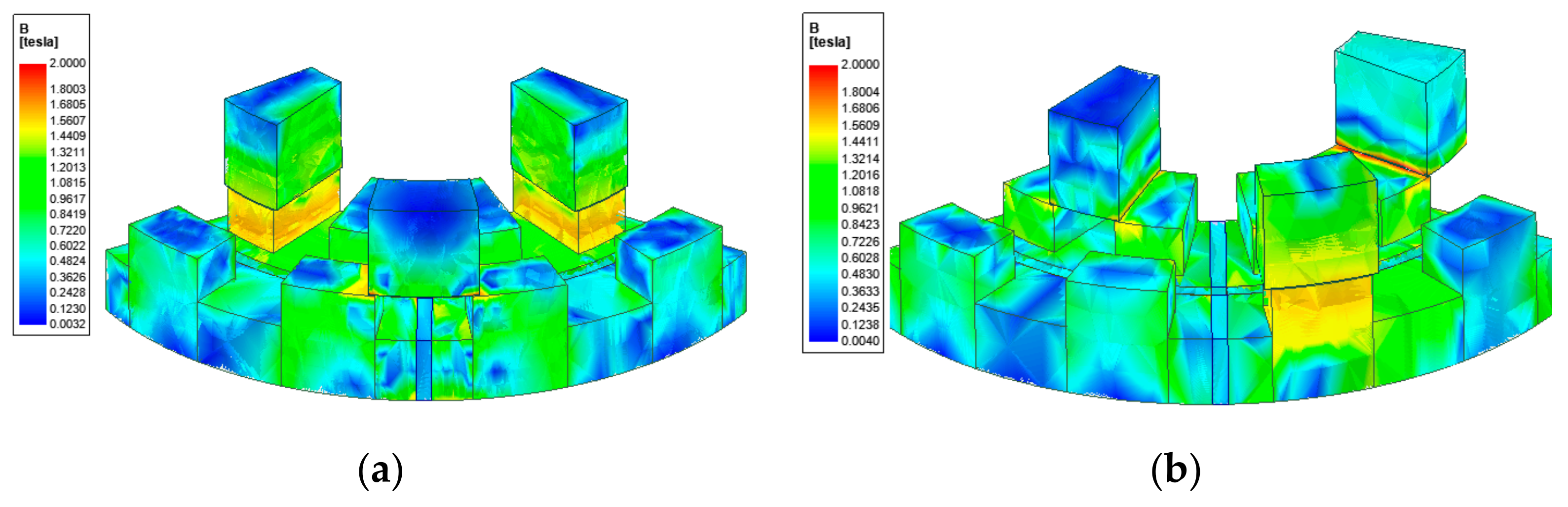
4.1. Open-Circuit Magnetic Field Distribution

Figure 16 shows the open-circuit magnetic field density distribution at two typical rotor positions. As shown in Figure 16a, when the axis of the outer rotor tooth is aligned with the permanent magnet located at the A-phase coils, the magnetic density of the upper part of the outer rotor teeth is close to 0. As the stator teeth on both sides of the permanent magnet have opposite magnetism, a magnetic leakage circuit is formed at the lower part of the outer rotor teeth. At this position, the magnetic flux of the A-phase armature winding is 0, which is consistent with the above analysis. When the outer rotor teeth only align with the right tooth of the A-phase stator pole, the magnetic flux density of this tooth is about 1.5 T. Therefore, the main magnetic circuit of the FSPM machine is not saturated.

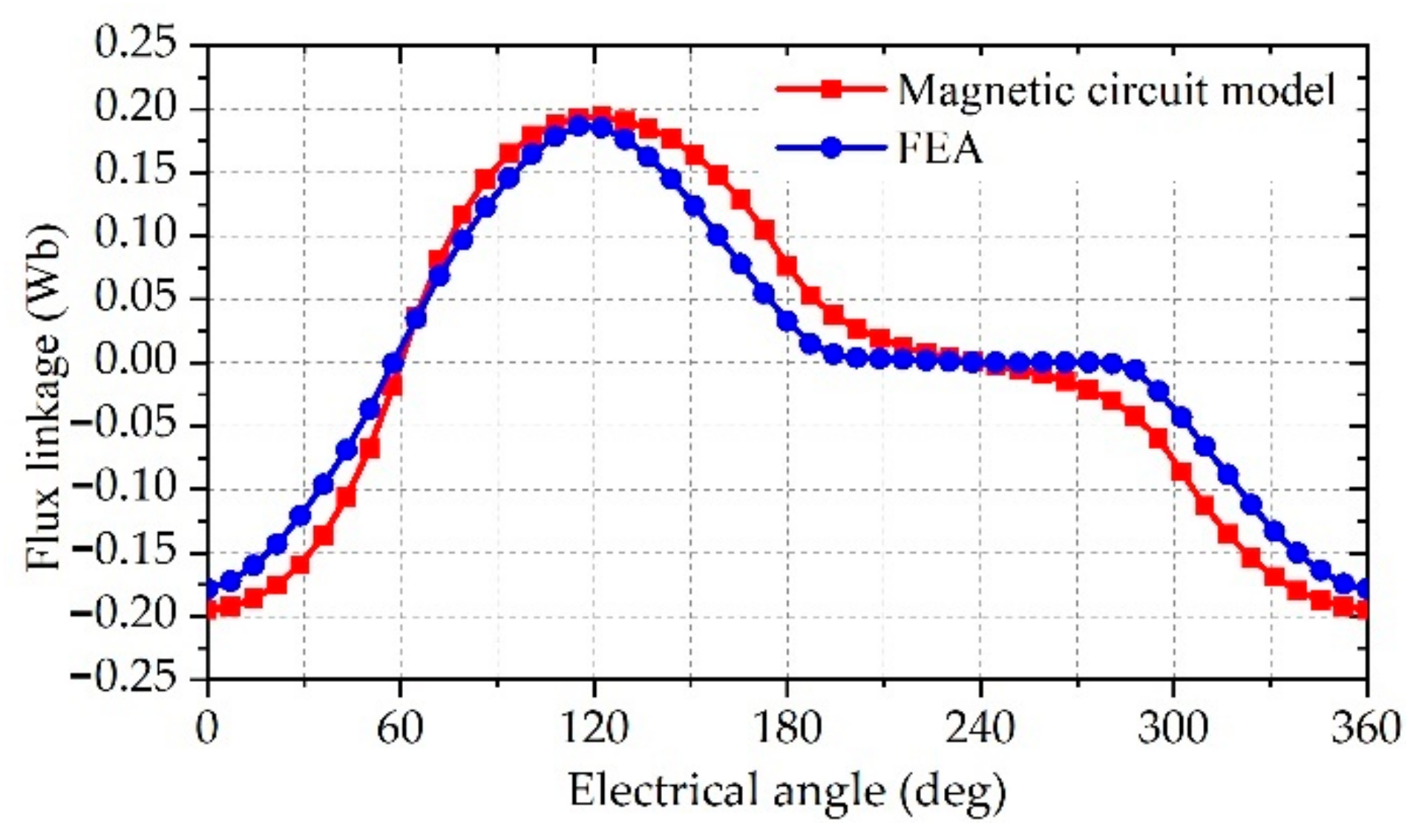
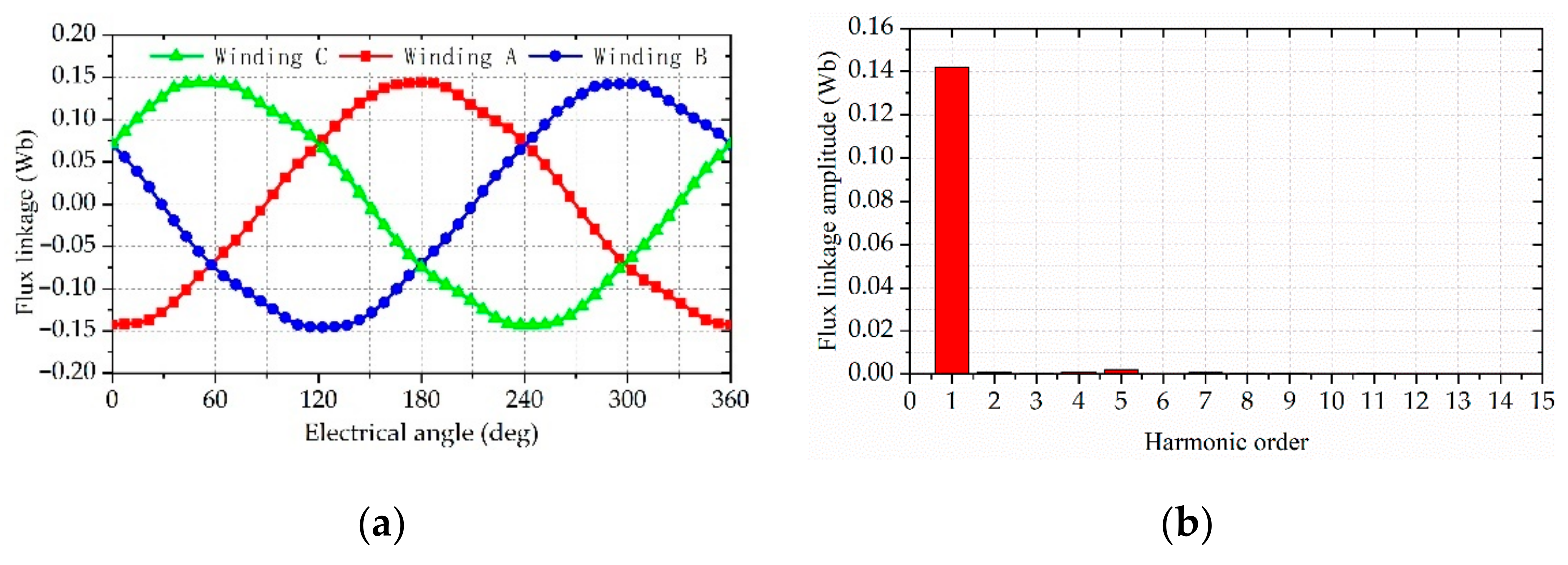
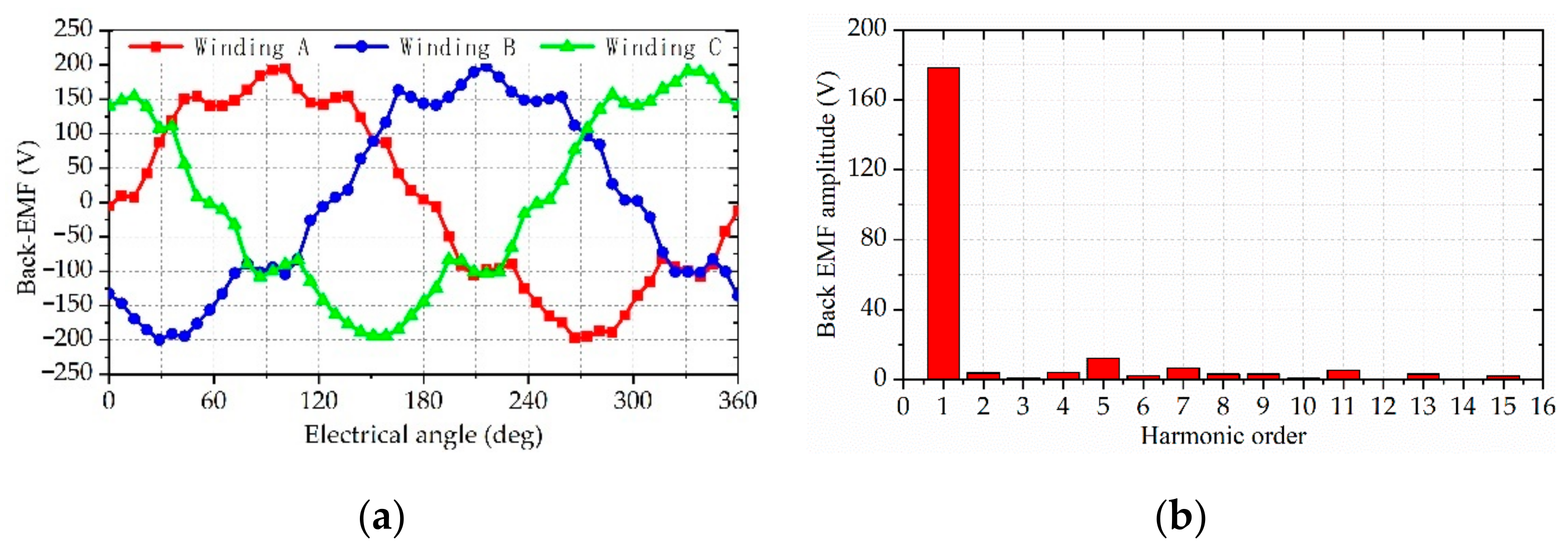
4.2. Open-Circuit Flux Linkage and Back-EMF
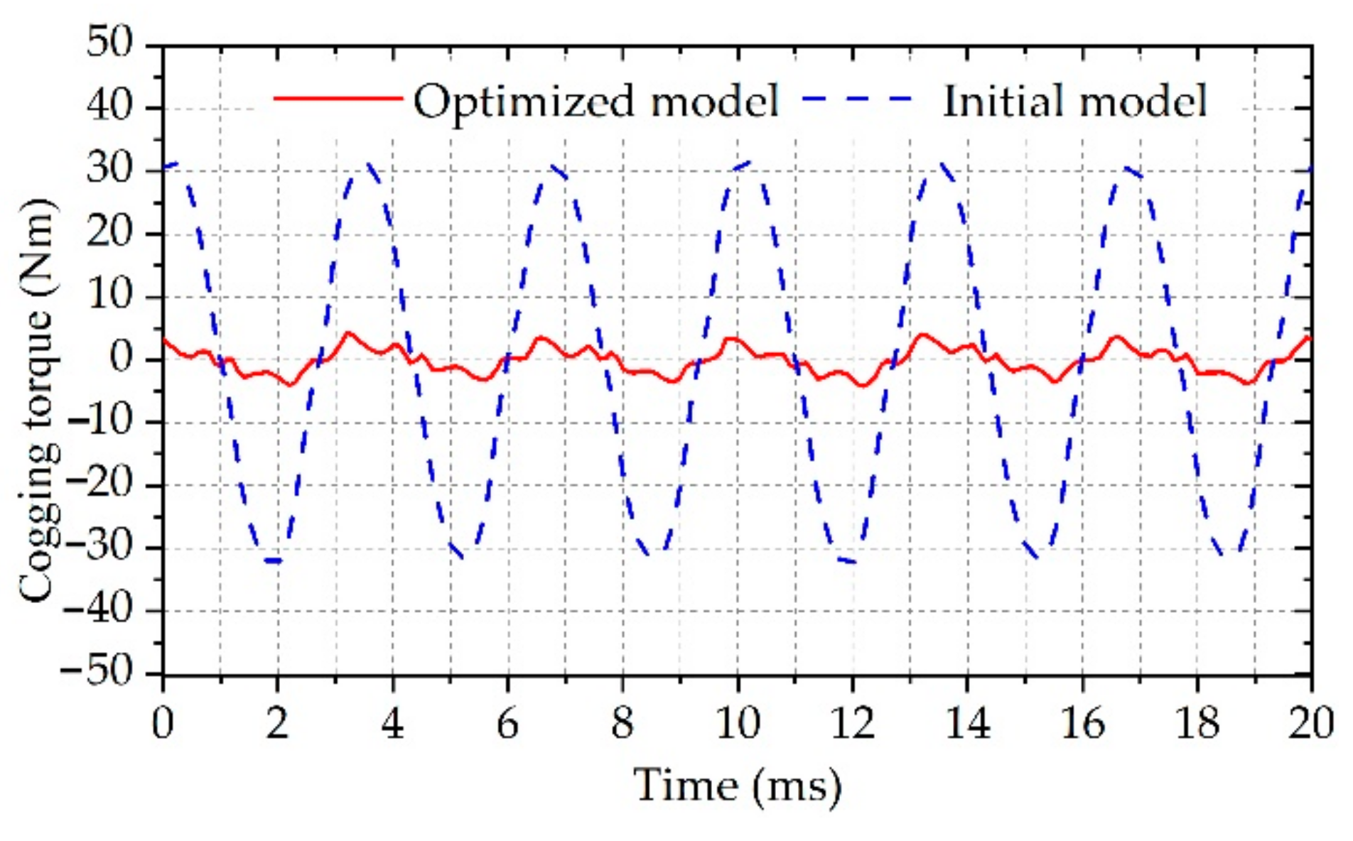
Figure 17 shows the three-phase winding flux linkage waveforms and FFT of the proposed 6/4 AxFSPM machine in the open circuit. It can be seen from Figure 17a that the flux linkage waveform of the three-phase winding is consistent and sinusoidal. At the same time, the FFT results of the flux linkage verify the above conclusions again, as shown in Figure 17b. The THD of the flux linkage waveform is only 2.5%. In addition, it must be noted that the odd harmonics contained in the flux waveform will still have a great negative impact on the performance of the motor, which needs to be eliminated by other optimization methods.
Figure 18 shows the phase back-EMF waveform of the 6/4 AxFSPM machine. The fundamental effective value of the back-EMF is 130 V. As shown in Figure 18b, the harmonic content of the back-EMF is significantly higher than that in the flux linkage, because the harmonic amplitude is amplified during the calculation of the back-EMF. In addition, the centralized winding of the proposed FSPM machine is also one of the reasons for the generation of multiple back-EMF harmonics. This harmonic can be generally eliminated by other auxiliary methods, such as skewing [21], dummy slots, and chamfering [22].

4.3. Cogging Torque

The larger cogging torque, which has a great influence on the output torque, is an inherent characteristic of the double-salient permanent magnet motor [23]. Therefore, the structure of the motor needs to be further optimized to reduce the cogging torque. Figure 19 shows a comparison of initial and optimized cogging torque waveforms. As shown in the figure, compared with the initial model, the cogging torque of the optimized model is significantly improved. Meanwhile, the amplitude of cogging torque is only 4.5 N, which can meet the optimization objective.

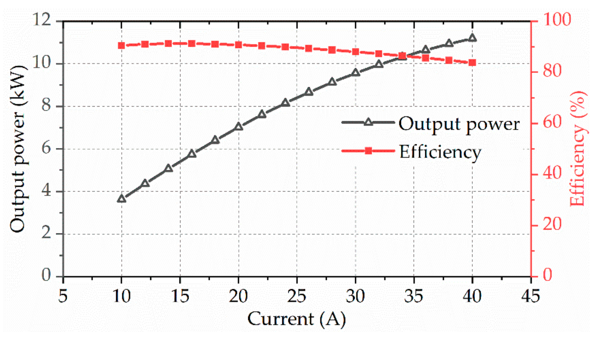
4.4. Output Power and Efficiency
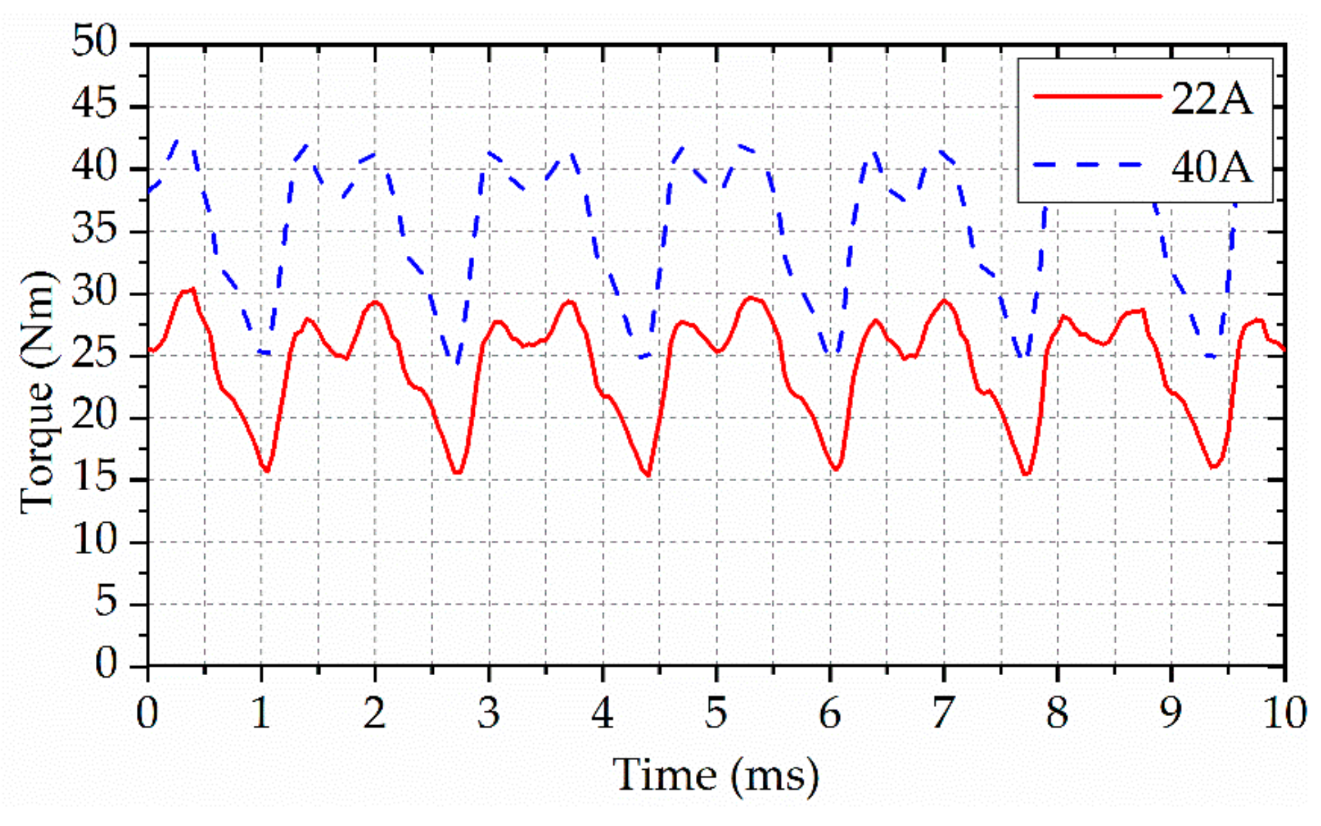
Figure 20 shows the output power and efficiency of the proposed 6/4 FSPM machine. It can be seen that with the increase in current, the output power of the machine increases gradually. However, when the current exceeds 30 A, the increase in output power begins to decrease. Meanwhile, the efficiency of the machine gradually decreases. The main reason is that the copper loss of the motor increases geometrically with the increase in current. According to the design requirements, the output power of the motor is 7.5 kW and the efficiency is 90%.

4.5. Output Torque

The rated load torque and 1.5-times load torque of the proposed 6/4 FSPM machine are shown in Figure 21. When the current is 22 A and 40 A, the average torque is 24.1 Nm and 35.8 Nm, respectively, and the peak-to-peak value of the torque is 15 Nm and 18 Nm, respectively. Although the peak-to-peak value of the torque increases with the increase in current, the torque ripple decreases slightly. The torque ripples of the rated load and 1.5-times load are 31.8% and 25.6%, respectively. The cogging torque accounts for a large proportion in the torque ripple, which leads to this phenomenon.

5. Discussion

To improve the unworkable properties of the conventional 6/4 FSPM machine, the generation principle of even-order harmonics in the flux linkage is analyzed in this paper. At present, most of the existing 6/4 motors use two identical stators [12,13,14,15,17] or two identical rotors [16] to eliminate even harmonics. Although the topologies of these motors are different, the principle of eliminating even harmonics is the same. In order to reduce the axial length of the motor, two stators with different sizes are nested along the radial direction and separated by PMs. Therefore, based on the adjustment of the angle of the inner and outer stators, it is also necessary to set the coils on the two stators to different turns to better eliminate even harmonics of the flux linkage, as shown in Figure 15.
Based on the principle of even harmonic elimination, the existing 6/4 FSPM machine has three possible configurations: stator shifting, rotor shifting, and a combination of shifting both the stator and rotor [17]. However, as the stator shifting leads to the increase in magnetic leakage, the proposed 6/4 AxFSPM machine has only one applicable topology, which is rotor shifting, to eliminate even harmonics.
In order to reflect the advantages of the proposed machine, some key characteristics are compared with existing FSPM machines, as listed Table 4. All machines need to adopt unified test conditions, so the speed, output power, and outer diameter should be set at 3000 rpm, 7.5 kW, and 300 mm, respectively. It can be observed from the comparison data that although the 12/10 FSPM machine has great advantages in cogging torque and THD of the back-EMF, the core loss is significantly greater than those of the other three machines, and the efficiency is 86%. The ratio of axial length to outer diameter of the proposed machine is smallest, only 0.33. Although the cogging torque of the proposed machine is larger than that of the radial FSPM machine, it is smaller than that of the axial FSPM machine with double rotors.
The analysis results from the FEA 3D model show that the flux linkage of the proposed machine only has few even harmonics, and the THD is 2.2%. Meanwhile, the proportions of the 2nd, 3rd, 5th, and 7th harmonics in the back-EMF to the fundamental component are 2.15%, 0.64%, 6.94%, and 3.83% respectively, so the THD of the back-EMF is up to 9.8%. In addition, the torque ripple is as high as 31.8% at the rated load. It is main reason that the poor back EMF waveform and the large cogging torque have a great impact on the torque ripple, so it is necessary to study more works to effectively improve the quality of output torque. Nevertheless, the advantages of the proposed 6/4 FSPM machine in narrow axial space and efficiency cannot be ignored; it is still a good candidate for specific high-speed operating environments.

6. Conclusions

This paper presents a novel 6/4 axial FSPM machine with a dual stator placed radially to eliminate even harmonics for high-speed operations. The back-EMF of the conventional 6/4 FSPM machine contains more even harmonics, which makes it unable to work normally. The fundamental topology of the proposed machine and the elimination of the even harmonics principle are introduced. The influence of different parameters on the electromagnetic performance is derived by using the MEC method. The results calculated by 3D FEA and the proposed MEC method have little error.
The optimized model is obtained by 3D FEA parametric scanning. The FEA results show that the proposed model not only reduces the THD of flux linkage from 60% to 2.2%, but also reduces the THD of the back-EMF to 9.8%. Moreover, the cogging torque of the optimized model only accounts for 15% of the cogging torque of the original model. The output power is 7.5 kW and the efficiency reaches up to 90%. In addition, compared with the existing 6/4 FSPM machine, the proposed 6/4 FSPM machine has greater advantages in a smaller axial length. In a future study, irreversible demagnetization, thermal characteristics, mechanical instability, sensorless control, and a prototype experiment will be carried out.

Author Contributions

H.Z. implemented the research, performed the analysis, and wrote the paper. L.J. conceived the idea of the research. H.Y. derived the equivalent magnetic circuit model. C.L. and B.X. collated simulation data. S.F. and Z.X. were responsible for guidance and manuscript editing. All authors have read and agreed to the published version of the manuscript.

Funding

This research was funded by the National Natural Science Foundation of China, grant number 51777029.

Institutional Review Board Statement

Not applicable.

Informed Consent Statement

Not applicable.

Data Availability Statement

Not applicable.

Conflicts of Interest

The authors declare no conflict of interest.

References

  1. Li, S.; Li, Y.; Choi, W.; Sarlioglu, B. High-Speed Electric Machines: Challenges and Design Considerations. IEEE Trans. Transp. Electrif. 2016, 2, 2–13. [Google Scholar] [CrossRef]
  2. Bianchi, N.; Bolognani, S.; Luise, F. Potentials and Limits of High-Speed PM Motors. IEEE Trans. Ind. Appl. 2004, 40, 1570–1578. [Google Scholar] [CrossRef]
  3. Tenconi, A.; Vaschetto, S.; Vigliani, A. Electrical Machines for High-Speed Applications: Design Considerations and Tradeoffs. IEEE Trans. Ind. Electron. 2014, 61, 3022–3029. [Google Scholar] [CrossRef]
  4. Zhang, Z.; Wang, C.; Geng, W. Design and Optimization of Halbach-Array PM Rotor for High-Speed Axial-Flux Permanent Magnet Machine with Ironless Stator. IEEE Trans. Ind. Electron. 2020, 67, 7269–7279. [Google Scholar] [CrossRef]
  5. Ou, J.; Liu, Y.; Doppelbauer, M. Comparison Study of a Surface-Mounted PM Rotor and an Interior PM Rotor Made from Amorphous Metal of High-Speed Motors. IEEE Trans. Ind. Electron. 2021, 68, 9148–9159. [Google Scholar] [CrossRef]
  6. Thomas, A.; Zhu, Z.; Jewell, G.; Howe, D. Flux-Switching PM Brushless Machines with Alternative Stator and Rotor Pole Combinations. In Proceedings of the 11th International Conference on Electrical Machines and Systems (ICEMS), Wuhan, China, 17–20 October 2008; pp. 2986–2991. [Google Scholar]
  7. Zhu, Z.; Chen, J. Advanced Flux-switching Permanent Magnet Brushless Machines. IEEE Trans. Magn. 2010, 46, 1447–1453. [Google Scholar] [CrossRef]
  8. Li, X.; Shen, F.; Yu, S.; Xue, Z. Flux-Regulation Principle and Performance Analysis of a Novel Axial Partitioned Stator Hybrid-Excitation Flux-Switching Machine Using Parallel Magnetic Circuit. IEEE Trans. Ind. Electron. 2021, 68, 6560–6573. [Google Scholar] [CrossRef]
  9. Chen, J.; Zhu, Z. Winding Configurations and Optimal Stator and Rotor Pole Combination of Flux-Switching PM Brushless AC Machines. IEEE Trans. Energy Convers. 2010, 25, 293–302. [Google Scholar] [CrossRef]
  10. Zhao, J.; Quan, X.; Sun, X.; Lin, M.; Niu, S. Influence of Rotor-Pole Number on Electromagnetic Performance of Novel Double-Rotor Hybrid Excited Axial Switched-Flux Permanent-Magnet Machines for EV/HEV Applications. IEEE Trans. Magn. 2020, 56, 3. [Google Scholar] [CrossRef]
  11. Hua, W.; Cheng, M.; Zhu, Z. Analysis and Optimization of Back EMF Waveform of a Flux-Switching Permanent Magnet Motor. IEEE Trans. Energy Convers. 2008, 23, 727–733. [Google Scholar] [CrossRef]
  12. Li, Y.; Li, S.; Yang, Y.; Sarlioglu, B. Analysis of Flux Switching Permanent Magnet Machine Design for High-Speed Applications. In Proceedings of the 2014 IEEE Energy Conversion Congress and Exposition (ECCE), Pittsburgh, PA, USA, 14–18 September 2014; pp. 302–309. [Google Scholar]
  13. Li, Y.; Bobba, D.; Sarlioglu, B. A Novel Dual-Stator Flux Switching Permanent Magnet Machine with Six Stator Slots and Four Rotor Poles Configuration. In Proceedings of the 2015 IEEE International Electric Machines & Drives Conference (IEMDC), Coeur d’Alene, ID, USA, 10–13 May 2015; pp. 1566–1572. [Google Scholar]
  14. Liu, M.; Li, Y.; Sixel, W.; Sarlioglu, B. Design and Testing of Low Pole Dual-Stator Flux-Switching Permanent Magnet Machine for Electric Vehicle Applications. IEEE Trans. Veh. Technol. 2020, 69, 1464–1472. [Google Scholar] [CrossRef]
  15. Yu, W.; Liu, K.; Hua, W.; Hu, M.; Zhang, Z.; Hu, J. A New High-Speed Dual-Stator Flux Switching Permanent Magnet Machine with Distributed Winding. IEEE Trans. Magn. 2022, 58, 2. [Google Scholar] [CrossRef]
  16. Kim, J.; Li, Y.; Sarlioglu, B. Novel Dual-Rotor Single-Stator Axial Flux Switching Permanent Magnet Machine with Even Harmonic Elimination Topology. In Proceedings of the 2015 Int Aegean Conference on Electrical Machines and Power Electronics (ACEMP), Side, Turkey, 2–4 September 2015; pp. 506–512. [Google Scholar]
  17. Kim, J.; Li, Y.; Sarlioglu, B. Novel Six-Slot Four-Pole Axial Flux-Switching Permanent Magnet Machine for Electric Vehicle. IEEE Trans. Transp. Electrif. 2017, 3, 108–117. [Google Scholar] [CrossRef]
  18. Bobba, D.; Li, Y.; Sarlioglu, B. Harmonic Analysis of Low Stator-Slot and Rotor-Pole Combination FSPM Machine Topology for High Speed. IEEE Trans. Magn. 2015, 51, 11. [Google Scholar] [CrossRef]
  19. Capponi, G.; Donato, D.; Caricchi, F. Recent Advances in Axial-Flux Permanent-Magnet Machine Technology. IEEE Trans. Ind. Appl. 2012, 48, 2190–2205. [Google Scholar] [CrossRef]
  20. Zhao, J.; Ma, T.; Liu, X.; Zhao, G.; Dong, N. Performance Analysis of a Coreless Axial-Flux PMSM by an Improved Magnetic Equivalent Circuit Model. IEEE Trans. Energy Convers. 2021, 36, 2120–2130. [Google Scholar] [CrossRef]
  21. Lin, M.; Zhang, L.; Li, X. Analysis on Cogging Torque in Axial Field Flux-Switching Permanent Magnet Machine. Electr. Mach. Control 2009, 13, 787–791. [Google Scholar]
  22. Zhu, H.; Xu, Y. Permanent Magnet Parameter Design and Performance Analysis of Bearingless Flux Switching Permanent Magnet Motor. IEEE Trans. Ind. Electron. 2021, 68, 4153–4163. [Google Scholar] [CrossRef]
  23. Chen, C.; Ren, X.; Li, D.; Qu, R.; Liu, K.; Zou, T. Torque Performance Enhancement of Flux-Switching Permanent Magnet Machines with Dual Sets of Magnet Arrangements. IEEE Trans. Transp. Electrif. 2021, 7, 2623–2634. [Google Scholar] [CrossRef]
Figure 1. 6/4 AxFSPM structure diagram: (a) exploded view; (b) vertical view; (c) stator core module.
Sustainability 14 07774 g001
Figure 2. Alternating magnetic flux path variation of the 6/4 FSPM within half an electric cycle: (a) electrical angle of initial position is 0; (b) 1/6 electric cycle; (c) 1/3 electric cycle; (d) 1/2 electric cycle.
Sustainability 14 07774 g002
Figure 3. Waveform and FFT of flux linkage of phase A: (a) flux linkage; (b) FFT of flux linkage.
Sustainability 14 07774 g003
Figure 4. Resultant magnet flux linkage waveform for total coils of phase A windings (A1 + A2 + A3 + A4).
Sustainability 14 07774 g004
Figure 5. FFT of the resultant magnet flux linkage waveform for total coils of phase A windings (A1 + A2 + A3 + A4).
Sustainability 14 07774 g005
Figure 6. Magnetic circuit model of a single stator module.
Sustainability 14 07774 g006
Figure 7. Magnetic circuit model of the rotor.
Sustainability 14 07774 g007
Figure 8. Different reluctance equivalent shapes: (a) cube; (b) vertical view.
Sustainability 14 07774 g008
Figure 9. Magnetic circuit model of the 6/4 FSPM machine under a pair of magnetic poles at 1/6 electric angle.
Sustainability 14 07774 g009
Figure 10. Comparison results of flux linkage between magnetic circuit model and FEA.
Sustainability 14 07774 g010
Figure 11. Proposed design optimization process.
Sustainability 14 07774 g011
Figure 12. The dimension parameters of the 6/4 FSPM machine: (a) cross-sectional view; (b) vertical view of rotor.
Sustainability 14 07774 g012
Figure 13. The dimension parameters of the 6/4 FSPM machine.
Sustainability 14 07774 g013
Figure 14. Influence of rotor yoke height on magnetic linkage amplitudes of phase A.
Sustainability 14 07774 g014
Figure 15. Influence of the inner coil turns on THD and amplitude of flux linkage.
Sustainability 14 07774 g015
Figure 16. 6/4 AxFSPM machine magnetic field density distribution at open-circuit: (a) Axis aligned of the outer PM and rotor pole. (b) Axis aligned of the outer stator teeth and rotor pole.
Sustainability 14 07774 g016
Figure 17. 6/4 AxFSPM machine flux linkage waveforms and FFT results: (a) Flux linkage waveforms. (b) FFT results of flux linkage.
Sustainability 14 07774 g017
Figure 18. 6/4 AxFSPM machine back-EMF waveforms and FFT results: (a) Back-EMF waveforms. (b) FFT result of back-EMF.
Sustainability 14 07774 g018
Figure 19. Comparison diagram of cogging torque.
Sustainability 14 07774 g019
Figure 20. Output power and efficiency of the proposed 6/4 FSPM machine.
Sustainability 14 07774 g020
Figure 21. Output torque of the proposed 6/4 FSPM machine.
Sustainability 14 07774 g021
Table 1. Comparison of high-speed FSPM machines.
Radial FSPM MachineAxial FSPM MachineProposed Model
Slot/pole12/10 [12]6/4 [14]6/4 [17]6/4
Axial lengthLongLongShortShortest
Fundamental frequencyHighLowLowLow
EfficiencylowHighHighHigh
Dissipate heatGoodBadBetterBetter
Table 2. The design variables of the 6/4 AxFSPM machine.
ParameterSymbolLowerUpperUnits
Stator yoke height L s _ e 1535mm
Stator tooth height h s _ t 1020mm
Inner stator tooth internal diameter r i i 90120mm
Inner stator tooth width w is 3050mm
Radial magnetized PMs inner diameter r PM 200240mm
Radial magnetized PMs thickness w PM _ r 36mm
Outer stator tooth internal diameter r oi 240260mm
Rotor yoke height L r _ e 1030mm
Rotor tooth angle θ r _ t 1545deg
Table 3. Optimized dimension parameters of the proposed 6/4 AxFSPM machine.
ParameterValueParameterValue
Turns of outer winding50Angle between inner and outer rotor teeth/deg45
Turns of inner winding68Rated speed (rpm)3000
Stator yoke height L s _ e (mm)28Outer stator tooth internal diameter r oi (mm)252
Stator tooth height h s _ t (mm)20Outer stator tooth width w os (mm)25
Inner stator tooth internal diameter r i i (mm)114Tangential magnetized PMs width w PM _ t (mm)6
Inner stator tooth width w is (mm)43.6Rotor yoke height L r _ e (mm)17
Radial magnetized PMs inner diameter r PM (mm)220Rotor tooth height h r _ t (mm)20
Radial magnetized PMs thickness w PM _ r (mm)6Rotor tooth angle θ r _ t (mm)17
Radial magnetized PMs angle θ PM _ r (deg)55Air gap height g δ (mm)1
Table 4. Key characteristics of FSPM machines.
Radial FSPM MachineAxial FSPM MachineProposed Model
Slot/pole12/10 [12]6/4 [14]6/4 [17]6/4
Number of stators1212
Number of rotors1121
Axial length/outer diameter (mm)0.580.830.570.33
Fundamental frequency (Hz)500200200200
Iron loss (W)524412425423
Efficiency (%)86919290
Cogging torque (Nm)0.32.321.54.5
THD of back-EMF (%)0.25.88.99.8
Publisher’s Note: MDPI stays neutral with regard to jurisdictional claims in published maps and institutional affiliations.

