Article

Systems Accounting for Carbon Emissions by Hydropower Plant

1
School of Economics and Management, China University of Geosciences, Beijing 100083, China
2
Beijing Engineering Corporation Limited, POWERCHINA, Beijing 100024, China
3
Department of Hydraulic Engineering, Tsinghua University, Beijing 100084, China
4
State Key Laboratory of Hydroscience and Engineering, Tsinghua University, Beijing 100084, China
5
Key Laboratory of Carrying Capacity Assessment for Resource and Environment, Ministry of Land and Resource, Beijing 100083, China
*
Author to whom correspondence should be addressed.
These authors contributed equally to this work.
Sustainability 2022, 14(11), 6939; https://doi.org/10.3390/su14116939
Submission received: 5 May 2022 / Revised: 28 May 2022 / Accepted: 30 May 2022 / Published: 6 June 2022
(This article belongs to the Special Issue Renewable Energy: Pathways towards Sustainable Development)

Abstract

:
Hydropower is the largest renewable source of electricity generation, the carbon emissions of which have attracted a lot attention. However, the system boundaries of existing studies are either incomplete or inaccurate. Therefore, this study provides a systems accounting framework for evaluating both the direct and indirect carbon emissions from a hydropower plant. It is based on the hybrid method as a combination of the process analysis and the input-output analysis. To demonstrate the framework, a case study for a typical pumped storage hydropower plant (NPSHP) is carried out. The total carbon emissions are estimated as 5828.39 kt in the life-cycle of the case system. The end-of-use stage causes the largest carbon emissions (38.4%), followed by the construction stage (34.5%), the operation stage (25.6%), and the preparation stage (1.5%). The direct carbon emissions are mainly released from sediments in the end-of-use stage and the surface of reservoirs in the operation stage (94.8%). The indirect carbon emissions are 2.8 times higher than the direct carbon emissions. The material, machinery, energy, and service inputs respectively account for 7.1%, 14.7%, 15.9%, and 62.3% of the total indirect carbon emissions by the case system. The indicator of EGOC (electricity generation on carbon emission) for the NPSHP is calculated as 26.06 g CO2-eq./kWh, which is lower than that of most other power plants.

1. Introduction

Renewable energy has received a lot of attention in recent years, and its relationship with carbon emissions has become a hot topic [1,2]. As the world’s largest renewable source of electricity generation [3], the nexus between hydropower and carbon emissions is complicated. On one hand, as is generally acknowledged, hydropower can produce clean and renewable electricity, which helps to avoid the massive carbon emissions released by thermal power plants. On the other hand, however, the hydropower itself can cause carbon emissions. It is mainly constituted of two parts. At first, the construction and operation of a hydropower plant are likely to alter the carbon cycle of the water ecosystem, which may lead to the direct carbon emissions increase. Secondly, the various product and service inputs during the whole life-cycle of a hydropower system would trigger greenhouse gas emissions during their manufacturing processes, which can be termed as the indirect carbon emissions through supply chains. Therefore, the carbon emission trade-off of hydropower has attracted a lot of scholars’ attention.
The direct carbon emissions released from the reservoir water surface of a hydropower plant have been intensively studied [4,5,6,7]. And the IHA (International Hydropower Association) published the guidelines of GHG Measurement for Freshwater Reservoirs [8]. The scholars acknowledge that hydropower is an important alternative energy source for mitigating the adverse effects of climate change. Meanwhile, they also highlight the uncertainty about whether the reservoir is a greenhouse gas emission source or sink with regard to the direct carbon emissions.
Apart from the direct carbon emissions, hydropower plants may also cause various indirect carbon emissions through the supply chains. For example, both construction materials used in the construction stage and machinery used in the end-of-use stage cause carbon emissions during their production processes. Some studies also paid attention to the indirect carbon emissions or the life-cycle (from cradle to gate or from cradle to grave) carbon footprint of hydropower. A majority of these studies are based on the method of process analysis [9,10,11,12,13]. It is found that the indirect carbon emissions caused by the hydropower project are significant. In some cases, they even exceed the direct carbon emissions. Therefore, the indirect carbon emissions of hydropower cannot be ignored.
The process analysis (PA) attempts to trace the key processes of the hydropower system along the supply chains as exhaustively as possible, and then sums up the carbon emissions of all traced processes to get the total life-cycle carbon emissions. However, the PA has several limitations. Firstly, the system boundaries in various studies are different from each other, making the results incomparable. Secondly, only part of the carbon emissions are taken into account due to the common truncation errors in the laborious traces. The input-output analysis (IOA) is another general method, parallel to the PA, to analyze the life-cycle (usually from cradle to gate) of a production system. Though avoiding the truncation error, the IOA can only give the average carbon emission result of the whole industry. Since the hydropower industry is usually not listed as a separate sector in the input-output table, the IOA cannot be directly applied to analyze the carbon emissions of hydropower. Even if listed, it cannot compare the carbon emission trade-off of different hydropower plants based on the highly aggregated results.
The hybrid method as a combination of the PA and the IOA was proposed by Bullard et al. to integrate the goods and remedy the drawbacks of both methods [14]. Using the PA-based inputs inventory and the IOA-based carbon emission intensity data, a lot of studies have estimated the life-cycle carbon emissions of various systems [15]. The environmental impacts, such as land footprint and carbon emissions, of renewable energy systems have also been studied by the hybrid method [16,17]. Li and his colleagues have carried out intensive studies to analyze the life-cycle carbon emissions of the reservoirs, especially these during the preparation and construction stages, using the hybrid method [18,19,20]. A few other studies are found to have applied the hybrid method, too [21,22]. These studies used the PA to build the material inputs inventory and the IOA-based carbon emission intensity database to approximate the upstream carbon emissions of various inputs.
Pumped storage hydropower (PSH) is a special kind of hydropower system that includes two reservoirs locating at different heights. When electric power is surplus, water is pumped from the lower reservoir to the higher reservoir for storage. When electric power is needed, water is released from the higher reservoir to the lower reservoir through turbines to generate electricity. PSH is usually described as a giant battery that stores electricity. The inherently cyclical nature of wind and solar power generation leads to the increasing need of power storage facilities to ensure the stability of power supply to the grid. PSH is now the world’s primary method of storing electricity. As of September 2021, PSHs accounted for 96.1% of global electricity storage capacity [23]. However, a limited number of studies have explored the relationship between PSH and carbon emissions. Most of these studies compared the PSHs with other electricity storage systems or other renewable energy systems based on the PA, and carbon emission was listed as an indicator to evaluate the environmental impact [24,25,26]. Wang et al. evaluated the water and carbon footprints of 50 hydropower plants in China by the hybrid method, 17 of which are pumped storage hydropower plants [27]. Li et al. used the PA to study the resource use and environmental impact of a pumped storage hydropower plant (PSHP) in Hubei Province of China [28].
The existing studies using the hybrid method still have shortcomings. Firstly, the carbon emissions induced by some inputs are neglected, and the system boundaries of these studies are incomplete. For example, services are key inputs in all stages of a hydropower plant, which can cause carbon emissions during the supply chains. However, the carbon emissions of service were not taken into account in previous studies. The carbon emissions by machinery during its production are overlooked, too. Secondly, in the context of global economic integration, the industries in different countries are highly interconnected and the production of each product requires a variety of inputs from the heterogeneous global economic system. The single-region input-output analysis ignoring the imported products cannot accurately trace the worldwide life-cycle carbon emissions of a product, the intensity data based on which are inaccurate, either. There are two input-output models that take inter-regional linkages into account, namely the multi-region input-output model (MRIO) and the multi-scale input-output model (MSIO). In theory, the MRIO is more accurate than the MSIO, but the MSIO requires less data than the MRIO. Moreover, currently, the MRIO data usually involves many assumptions due to lacking of detailed sector-level trade statistics, which greatly undermine the reliability of the results [29,30]. Therefore, both the MRIO and MSIO-based intensity database are suitable to provide accurate results for carbon emissions accounting of a hydropower plant. Thirdly, rather than matching the year and economy when and where the target plant was constructed, the carbon emissions intensity data adopted in these studies were for the other countries or from many years ago. Either technical efficiencies or economic structures are not the same among different countries or one country in different years. The misuse of intensity data would introduce considerable deviations.
The aim of this paper is to present a systems accounting framework to calculate the life-cycle carbon emissions of a hydropower plant. It is based on the hybrid method as a combination of the process analysis and the input-output analysis, which is suitable to trace the carbon emissions of a specific hydropower plant. Meantime, it can present us with more accurate results (by using the MRIO or MSIO-based database concerning the consistent year and place) under a relatively complete system boundary (by taking all products and service inputs into account). By doing so, the problems in previous studies aforementioned can be efficiently avoided. The framework is then applied to a case pumped storage hydropower plant to analyze both the direct and indirect carbon emissions during the whole life cycle. At last, the efficiency of the case plant in reducing carbon emissions is evaluated, which can be used to guide the development of PSH in the future.

2. Methodology

2.1. Framework of Life-Cycle Carbon Emissions Accounting for a Hydropower Plant

The total carbon emissions ( CE ) during the whole life-cycle of a hydropower plant consist of the direct and indirect carbon emissions (see Figure 1), which can be calculated from:
CE = CE d + CE i
where CE d and CE i represent the direct and indirect carbon emissions of a hydropower plant, respectively.
The life-cycle of a hydropower plant can be divided into four stages, which are the preparation stage, the construction stage, the operation stage, and the end-of-use stage. The sources of carbon emissions are different for each stage. The procedures to calculate them are described as following.

2.1.1. Direct Carbon Emissions Accounting

The direct carbon emissions from a hydropower plant consist of three main components: carbon emissions from fossil fuels combustion during the whole life-cycle, carbon emissions released from the surface of the reservoir during the operation stage, and carbon emissions released from sediments during the end-of-use stage. The formula to calculate the direct carbon emissions of a hydropower plant is:
CE d = CE f d + CE r d + CE s d
where CE f d , CE r d , and CE s d represent the direct carbon emissions from three sources respectively. The most accurate way to record the direct carbon emissions is to conduct on-site experimental measurements over long periods of time. Considering that such measurements are usually hard to carry out due to various realistic constraints, this study provides an empirical method to calculate the direct carbon emissions of a hydropower plant. The three main sources of the direct carbon emissions and their calculation methods are as follows:
(1)
Fossil fuels combustion.
The fossil fuels are used by various machinery and transportation equipments throughout the whole life-cycle of a hydropower plant. For example, double-wheel trench cutters are used to build the underground continuous wall of the dam, and bulldozers are used to demolish buildings during the preparation and end-of-use stages. Trucks are often required to transport machinery and materials in the construction projects, which usually consume gasoline or diesel. The direct greenhouse gas emitted by fossil fuels combustion can be expressed as:
CE f d = i ε i d Q i
where ε i d and Q i are the carbon emission factor and consumption amount of i -th fossil fuel, respectively.
(2)
Reservoir surface release.
Greenhouse gases are emitted during the operation stage of a hydropower plant through the reservoir surface, which are mainly caused by the respiration of organic matter and the diffusion of gas in water. They can be calculated from:
CE r d = ε r d S r T
where ε r d is the per area per time carbon emission factor; S r is the area of the reservoir; T is the operation time of the hydropower plant.
(3)
Carbon release from sediment.
There are two main sources of sediment in the reservoir: one is sediment flowing into the reservoir through the river, and the other is generated by the death of plankton in the reservoir [31]. When the reservoir is demolished, the sediment will be exposed to the air and release carbon emissions through the decomposition of microbes in it. The equation is as following:
CE s d = ε s d S s
where ε s d is the per area carbon emission factor of the sediment; S s is the area of the sediment.

2.1.2. Indirect Carbon Emissions Accounting

The hybrid method is applied to trace the indirect carbon emissions of a hydropower plant. The procedures are described as follows.
(1)
Categorize all inputs to form the inventory.
The life-cycle inputs of a hydropower plant are classified into four major categories as material, machinery, energy, and service. Itemize all the products required in the life-cycle of a hydropower plant and attribute them into four categories to form the inputs inventory. The inventory includes the unit price, quantity, and monetary cost of each product or service ( C j i ).
(2)
Choose an appropriate embodied carbon emission intensity database for all inputs.
When selecting a proper database, it is important to consider two principles. First, the year of the input-output table should be close to the year when the target hydropower plant was constructed; second, each type of input should be attributed to the production industry listed in the input-output table. Manpower is needed in different stages of a hydropower plant, which can be also classified into a corresponding service industry. For example, the maintenance in the operation stage can be seen as professional technological service provided by the sector of Water, Environment and Municipal Engineering Conservancy.
(3)
Calculate the indirect carbon emissions of each input.
Firstly, each input of the inventory is matched to the production sector in the input-output table. Then the embodied carbon emission intensity ( I j i ) of the sector in the database is approximated as the intensity of the input. Multiply each input’s monetary cost by its embodied carbon emission intensity to obtain the embodied carbon emissions ( ECE j i ), then the total indirect carbon emissions ( CE i ) of a hydropower plant are readily obtained as:
CE i j ECE j i = j ( C j i I j i )

2.2. Indicator

As a widely used indicator in the net energy analysis, EROI is defined as the ratio of the energy extracted or delivered by an energy supply system to the energy consumed directly and indirectly in its supply chains [32]. Similarly, the indicator of electricity generation on carbon emissions (EGOC) is proposed in this paper for comparing the carbon emissions among different power plants upon generating electricity. It is defined as the total carbon emissions emitted by the power plant (including hydropower plant and PSHP) by generating unit electricity. It can be known that the lower the value, the more environment-friendly the system. The equation is as following:
EGOC = CE E
where E is the electricity gain during the entire life-cycle of a power plant. The PSHP is different from common hydropower plants, which need to consume electricity during water storage. It is assumed that the electricity power would be wasted if it is not stored by the PSHP (that’s what excess electricity means and what a PSHP is for). Therefore, the electricity consumed during pumping are regarded as costless, and the total electricity generated is considered as the electricity gain of the PSHP in this paper.

3. Case Study

3.1. Case Description

The N pumped storage hydropower plant (NPSHP) is chosen as the case system in this paper with an operation time of 100 years. It plays a significant role in supporting the safe & stable operation and enhancing system regulation capacity of local power grid, as well as promoting clean and low-carbon transformation of local energy system. There are three main greenhouse gases responsible for global warming: carbon dioxide (CO2), methane (CH4) and nitrous oxide (N2O). Since nitrous oxide contributes a small proportion (about 5%) to global warming [33], it is not included in this study. The methane emissions are mainly from lakes and wetlands, which are closely related to hydropower plants [34]. Therefore, CO2 and CH4 are considered in this study. According to IPCC and previous studies [35,36], the GWP (global warming potential) coefficients of CO2:CH4 as 1:21 are applied to calculate equivalent CO2 emissions (CO2-eq.) in this study.

3.2. The Carbon Emissions Accounting of the Case Plant

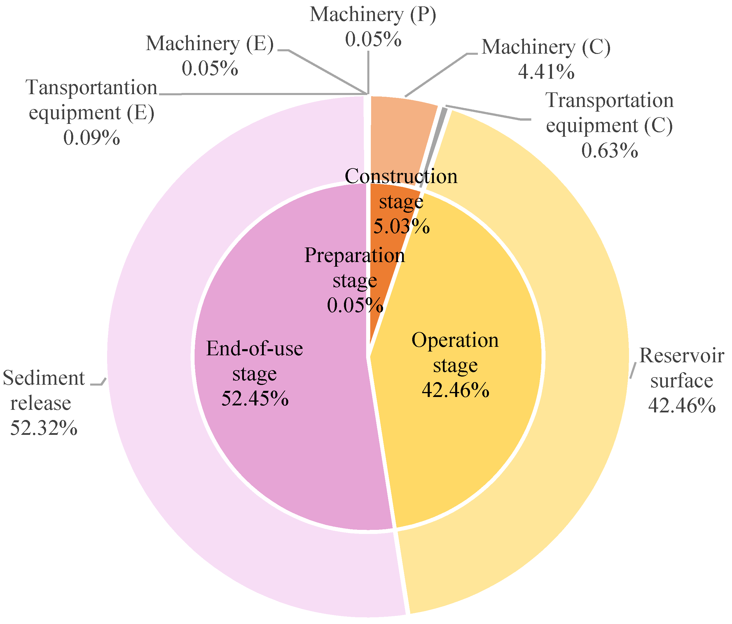
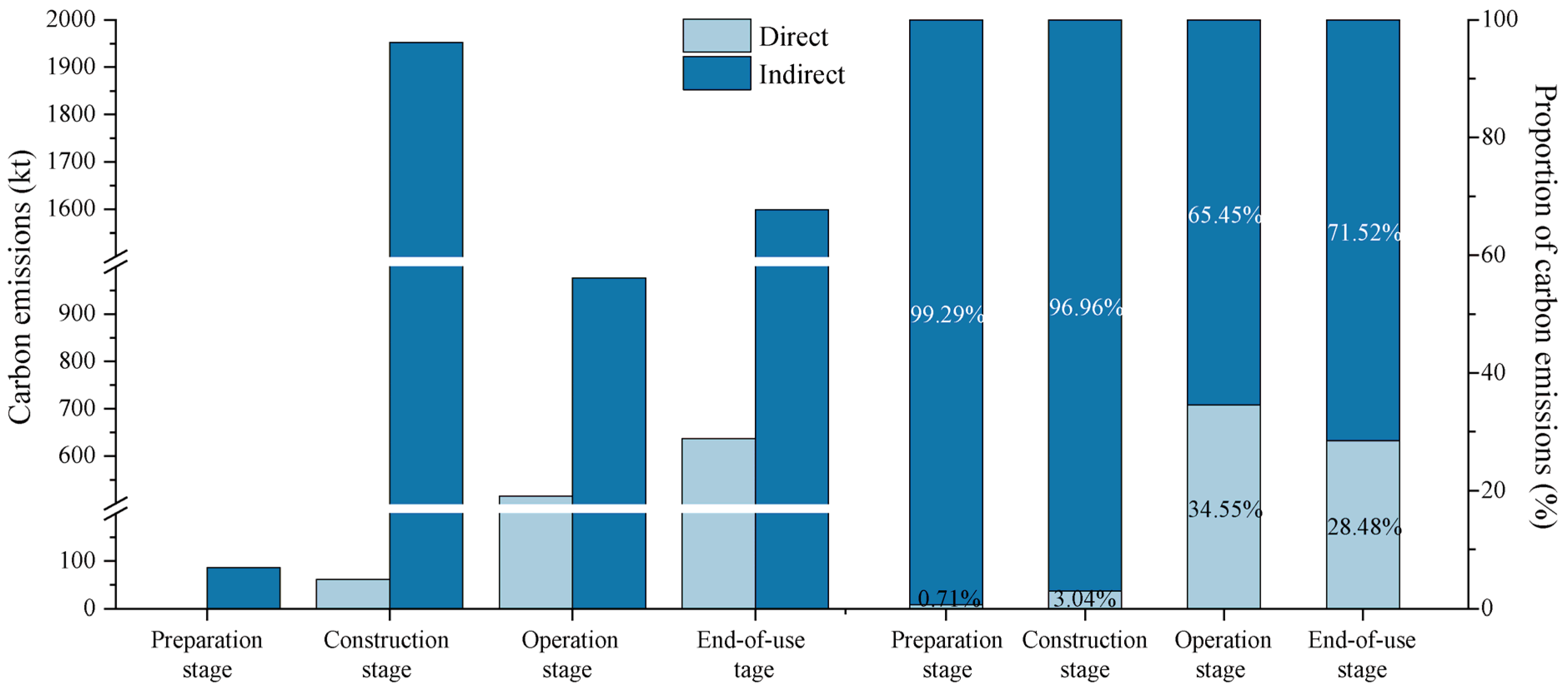
3.2.1. Direct Carbon Emissions

The in-site measurement is not performed for the case plant, and the direct carbon emissions of the case system are estimated by the empirical method in this paper. In order to calculate the direct carbon emissions caused by fossil fuels combustion of various machinery and transportation equipment, the carbon emission factors from EPA are adopted [37]. The amounts of fossil fuels consumption are from the BOQ (Bill of Quantities) of the case plant. The NPSHP is still in operation, so the fossil fuels consumption inventory in the end-of-use stage cannot be obtained directly. It is estimated that about 10% of the fossil fuels are consumed in the construction stage as proposed in Hertwich et al. [38].
The direct carbon emissions released from the reservoir surface are closely related to the climatic conditions and geographical location of the reservoir. In this paper, we used the average emission factors of CH4 and CO2 measured by Beaulieu et al. [39]. Because the latitude location, climatic conditions, and land types are similar between the reservoirs they measured and the NPSHP. According to the method proposed by Pacca and the organic carbon accumulation rates from Luo et al., per area carbon emission factor of the sediments is set as 0.91 g CO2-eq./m2/year [31,40]. The reservoir area is determined according to the BOQ of the NPSHP.
The direct carbon emissions during the life-cycle of the NPSHP are calculated as 1214.31 kt CO2-eq. The components of the direct carbon emissions are shown in Figure 2. Among the four stages, carbon emissions from the end-of-use stage are the highest (636.95 kt), followed by the operation stage (515.61 kt) and the construction stage (61.14 kt), and the carbon emissions from preparation stage are the least (0.61 kt). In the end-of-use stage, the direct carbon emissions are mainly from sediments and fossil fuels consumed by machinery to demolish dams and transportation equipment to transport wastes and recycled materials after dam demolition. The sediments account for a larger proportion (52.32% of the life-cycle direct carbon emissions). Li et al. found that the potential GHG emissions from reservoir sediments in the end-of-use stage were among the most sensitive factors in life-cycle GHG emissions [19], which should be paid attention to in evaluating the climate change impact of hydropower. The direct carbon emissions caused by fossil fuels consumed by machinery and transportation equipment in the end-of-use stage are negligible compared with those released from sediments. The carbon emissions released from reservoir surface during the operation stage account for 42.46% of the total life-cycle direct carbon emissions. They are mainly caused by the respiration of organic matter and the diffusion of gas in the reservoir. Therefore, reducing the amount of organic matter by routine removal of organic matter before impoundment help to reduce carbon emissions from reservoir surface. As for the construction stage, fossil fuels consumed by the machinery account for 4.41% of the total direct carbon emissions, and transportation equipment shares 0.63%. The direct carbon emissions during the preparation stage account for only 0.05% of the total direct carbon emissions, which comes from the fossil fuels consumed by machinery use in this stage.

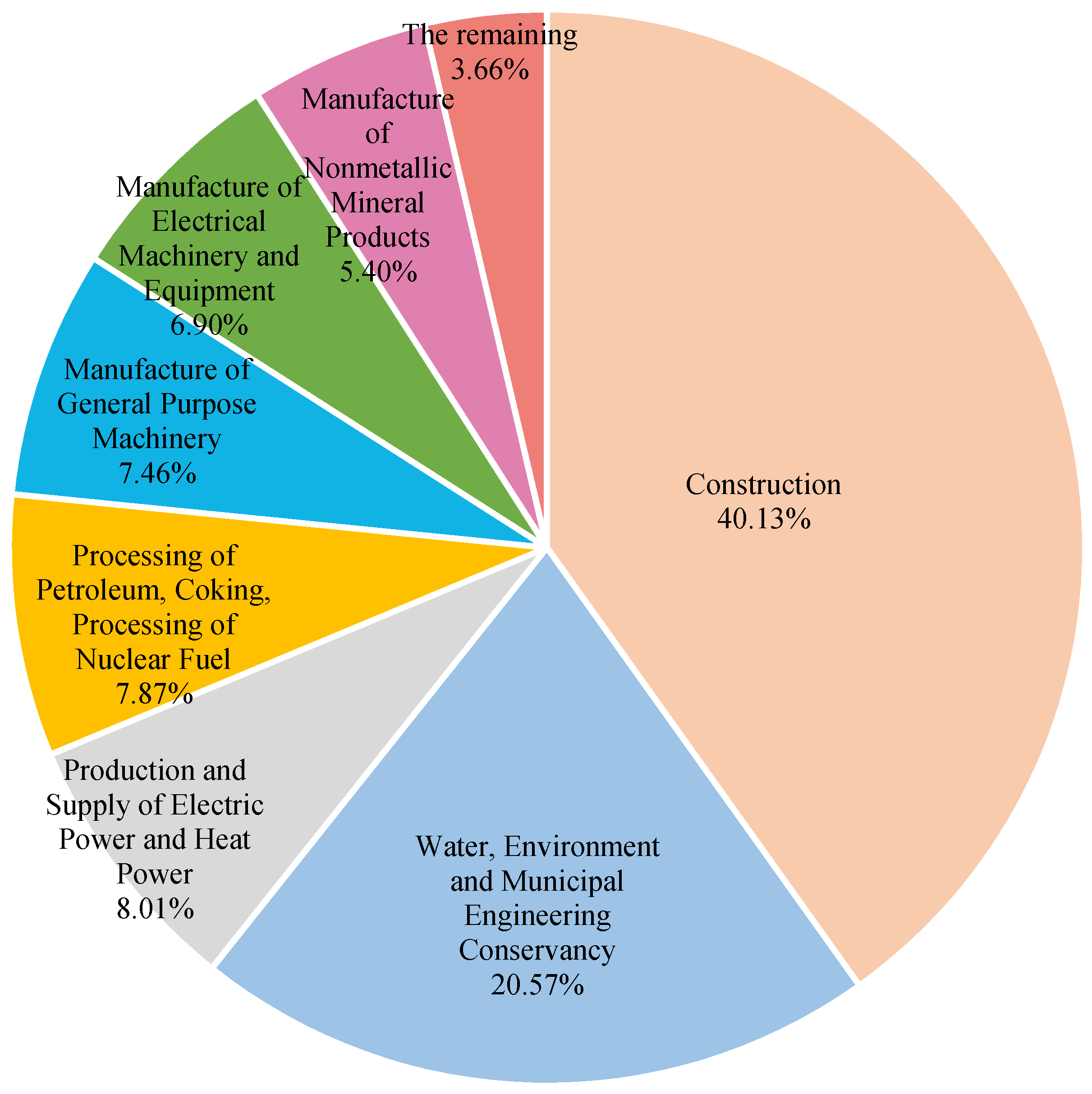
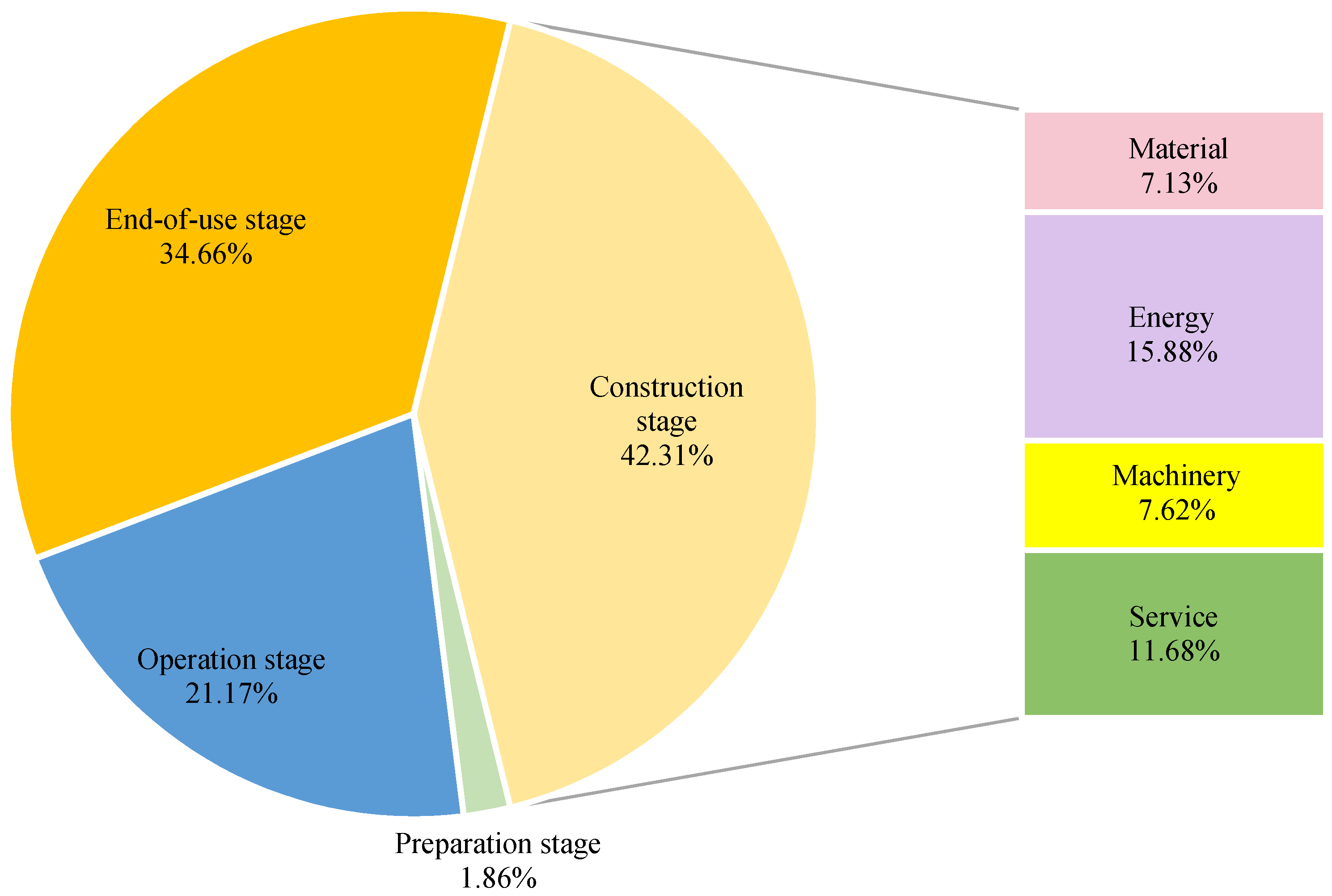
3.2.2. Indirect Carbon Emissions

As for the indirect carbon emissions, the hybrid method is employed to trace the historical carbon emissions of the product and service inputs. The inputs inventory data comes from the BOQ of the NPSHP. The indirect carbon emissions of each input can be obtained by multiplying the monetary cost of the input by the corresponding carbon emission intensity. Since the NPSHP was built in China in recent years, so the embodied carbon emission intensity database for the Chinese economy in 2017 by Zhan et al. is adopted [41]. All the inputs are divided into material, machinery, energy, and service, and the corresponding sector code and contents of each input are listed in Table 1.
The total indirect carbon emissions of the NPSHP are calculated as 4614.09 kt CO2-eq., 2.80 times higher than the direct carbon emissions. As is shown in Figure 3, the top three sources of the indirect carbon emissions are the products and services from the sectors of Construction (40.13%), Water, Environment and Municipal Engineering Conservancy (20.57%), and Production and Supply of Electric Power and Heat Power (8.01%). In total the service inputs account for 62.34% of the total indirect carbon emissions by the NPSHP. Therefore, it is important to take service into account to analyze the real carbon emissions cost of hydropower.
As for different stages (see Figure 4), the construction stage has the largest indirect carbon emissions, accounting for 42.31% of the total indirect carbon emissions. It is followed by the end-of-use and operation stage, which account for 34.66% and 21.17%, respectively. The preparation stage causes the least indirect carbon emissions (1.86%). The construction stage involves a lot of inputs, in which material inputs account for 7.13%, energy inputs for 15.88%, machinery inputs for 7.62%, and service inputs for 11.68%. As for the end-of-use stage, the indirect carbon emissions are mainly caused by the material inputs for dam decommission. In the operation stage, the indirect carbon emissions are mainly caused by the inputs for replacing the machinery and maintaining the building. In the preparation stage, the indirect carbon emissions are mainly caused by the service inputs for the emigrant relocation.

3.2.3. The Life-Cycle Carbon Emissions

Figure 5 shows the direct and indirect carbon emissions of the NPSHP. The total carbon emissions of the NPSHP are calculated as 5828.39 kt CO2-eq. in the life-cycle. As for the four stages, carbon emissions from the end-of-use stage account for the largest proportion (38.37%), followed by the construction stage (34.54%), the operation stage (25.60%), and the preparation stage (1.49%). The indirect carbon emissions are larger than the direct ones in each of the stages, the proportions of which are 99.29%, 96.96%, 65.45% and 71.52% from the preparation stage to the end-of-use stage, respectively. It is revealed that the indirect carbon emissions are the main component of life-cycle carbon emissions from the NPSHP.
The finding is in accord with that of some previous studies. Li et al. studied the life-cycle carbon emissions of five hydropower plants in China [19]. As for the proportions of carbon emissions by different stages among the five hydropower plants studied, the preparation stage is between 0.3–2.1%; the construction stage is between 6.8–24.4%; the operation stage and the end-of-use stage are relatively high, which are between 26.4–66.3% and 24.9–45.3%, respectively. The carbon emissions proportion of the preparation stage is similar to that of the NPSHP. For the construction stage, the NPSHP has a higher proportion of carbon emissions. This is because this study also considers the inputs of energy and manpower in the construction stage. As for the operation and end-of-use stages, the proportions of the NPSHP are within the ranges of the previous study.

4. Discussion

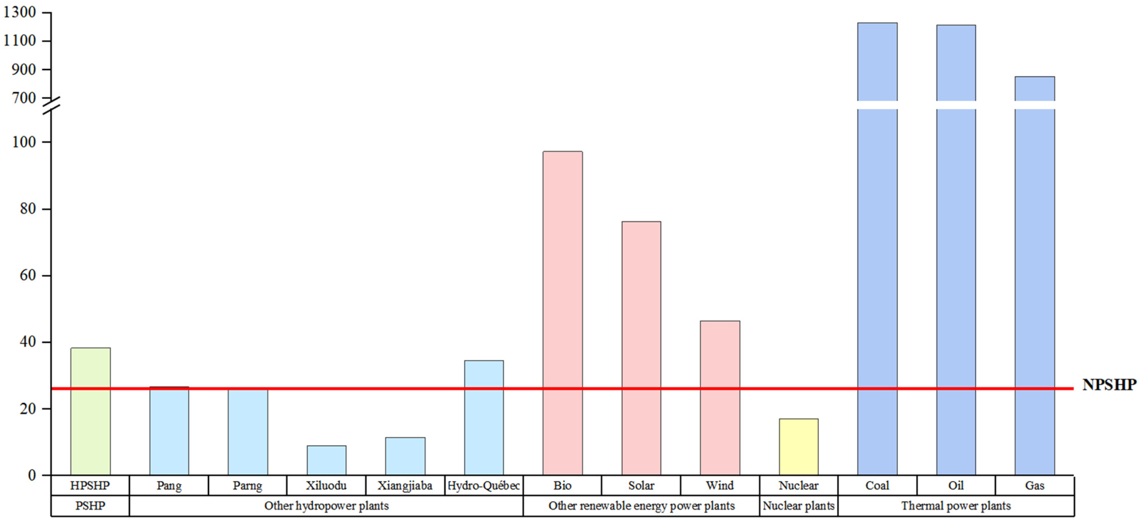
4.1. Comparison with Other Power Plants

The indicator of EGOC is proposed in this paper, which can be used to compare the environmental efficiencies of different power plants. The EGOC of the NPSHP is calculated as 26.06 g CO2-eq./kWh. There are limited studies on the life-cycle carbon emissions of PSHP. Li et al. studied the life-cycle environmental impact of a PSHP in Hubei province of China (HPSHP) [28]. It is reported that the EGOC of the HPSHP is 38.3 g CO2-eq./kWh (a life span of 30 years), which is of the same order of magnitude but higher than that of the NPSHP. The NPSHP is shown more environment-friendly in terms of carbon emissions than the HPSHP. As the annual power output of the NPSHP is much higher than the HPSHP, the scale effect may also contribute to this.
The EGOC of the NPSHP is also compared with that of other hydropower plants and energy power plants (See Figure 6). Hydropower plants can be divided into reservoir plants and run-of-river hydropower plants [42]. Pang and Parng are run-of-river hydropower plants in India [43], and Xiangjiaba and Xiluodu are reservoir hydropower plants in China [19]. Hydro-Québec is the aggregated data for 63 hydropower plants (including both reservoir plants and run-of-river hydropower plants) in Québec [11]. Among them, the EGOC of Pang and Parng were calculated as 26.63 g CO2-eq./kWh and 25.85 g CO2-eq./kWh, which are similar with that of the NPSHP. The EGOC of Xiangjiaba and Xiluodu were calculated as 9 g CO2-eq./kWh and 11.4 g CO2-eq./kWh, much lower than the NPSHP. The average EGOC of 63 hydropower plants was calculated as 34.5 g CO2-eq./kWh, slightly higher than that of the NPSHP.
The EGOC of other renewable energy power plants, nuclear power plants, and thermal power plants from Geller et al. are also shown in Figure 6 [44]. Biomass, solar-PV, and wind are considered as other renewable energy power plants. Among them, the biomass power plant had the largest EGOC of 97.3 g CO2-eq./kWh. The EGOC of the solar-PV power plants and wind power plants were 76.3 g CO2-eq./kWh and 46.4 g CO2-eq./kWh, which are lower than the biomass power plants, but much higher than the NPSHP. The EGOC of the nuclear power plant was calculated as 17.1 g CO2-eq./kWh, lower than the NPSHP. The electricity generated by thermal power plants depends on fossil fuel combustion to generate electricity, which causes a lot of carbon emissions. The EGOC of coal-fired, oil-fired, and gas-fired power plants were calculated as 1230 g CO2-eq./kWh, 1213 g CO2-eq./kWh, and 855 g CO2-eq./kWh, respectively. It is revealed that the NPSHP is much more environmental efficient in reducing emissions than conventional thermal power plants.

4.2. Uncertainty and Outlook

The uncertainty and limitation in this paper are mainly caused by data acquisition constraints. At first, carbon emission intensity is calculated according to the 2017 input-output table of China, but some of the inputs of the case system may be produced in other years. It may lead to some errors, which can be ignored as the manufacturing technology would not change too much during a short time. Secondly, the BOQ of the case system in the construction stage is not detailed enough. For example, the fossil fuels utilized by the machinery are not listed in the BOQ, which is estimated by the monetary cost and average prize of diesel. Thirdly, since the NPSHP has just begun operating, there is a lack of the inputs inventory for the operation and end-of-use stages. The accepted PSHP practices as well as the empiric methods are applied to estimate the corresponding BOQ during these stages. For example, in the end-of-use stage, the fossil fuels consumed during demolition is estimated as 10% of which in the construction stage as proposed by Hertwich et al. [38]. All these uncertainties are common in life-cycle studies. The main purpose of this study is to contribute a systems accounting framework for carbon emissions by a hydropower plant, which has overcome the shortcomings of previous studies, such as incomplete system boundary and misused intensity data. It is believed that the deviations caused by these uncertainties are negligible.
Under various climate change mitigation targets, the demand for renewable energy will increase very fast in the future [45]. According to China’s plan for peaking carbon dioxide emissions before 2030, carbon emissions per unit of GDP in 2025 will decrease by 18% compared with 2020 and decrease by 65% in 2030 compared with 2005. Considering that the thermal power accounts for 70% of China’s total power generation now, it is foreseeable that the future demand for renewable energy in China will be very huge. Due to the cyclical nature and instability of renewable energy sources such as wind and solar, the need for peak and valley regulation and stability of the power system will increase significantly, too. PSHP is widely regarded as a useful way to store electricity. However, the installed capacity of pumped storage power stations currently accounts for only 1.4% of total installed power generation capacity in China, and there is still a big gap compared with Europe and the United States (more than 10%). China has made a medium and long-term development plan for pumped hydropower storage [46]. It is projected that the total scale of pumped storage will reach more than 62 million kW by 2025 and around 120 million kW by 2030, 1.91 and 3.69 times as much as it is now. Although the life-cycle carbon emissions per unit of electricity generated by PSHP are lower than thermal power plants, the carbon emissions generated by a large number of new PSHPs still should be paid attention to in the future.

5. Conclusions

Renewable energy plays an increasingly important role worldwide. As a typical renewable energy source, hydropower makes great contribution to global electricity generation. The carbon emissions reduction benefit of hydropower by avoiding the massive carbon emissions of thermal power plants has been widely acknowledged. However, the construction and operation of hydropower plants would cause in-site and off-site carbon emissions, which should be taken into account to present a full picture of hydropower’s environmental impacts. Although a lot of previous studies have calculated the life-cycle carbon emissions of hydropower plants based on different methods, they suffered from shortcomings in terms of incomplete system boundary or misuse of intensity data. To tackle these problems, this paper provides a systems accounting framework to estimate both the direct and indirect carbon emissions of a hydropower plant. It relies on the hybrid method as a combination of the process analysis method and the input-output analysis method. An indicator of EGOC is also proposed to assess the efficiency in reducing carbon emissions among different power plants. The standard framework proposed herein can be extended to any hydropower plant to support the life-cycle carbon emissions accounting.
As a novel form of hydropower, PSH can coordinate with other electricity generation technologies to ensure a safe and stable power system, which has attracted a lot of attention recently. A case study of a typical PSHP is carried out based on the proposed framework. It is estimated that the NPSHP causes 5828.39 kt CO2-eq. during the life-cycle, of which the indirect carbon emissions account for 79.17%. The proportions of carbon emissions in the preparation stage, the construction stage, the operation stage, and the end-of-use stage are 1.49%, 34.55%, 25.60%, and 38.37%, respectively. The direct carbon emissions are mainly released from sediments in the end-of-use stage and the surface of reservoirs in the operation stage (94.78%). As a result, the end-of-use and operation stages account for 52.45% and 42.46% of the total direct carbon emissions, respectively. The indirect carbon emissions are caused by the product and service inputs during the life-cycle. The indirect carbon emissions in the construction stage are the largest among the four stages, accounting for 42.31%, of which the energy inputs share the most (15.88%), followed by the service inputs (11.68%), the machinery inputs (7.62%), and the material inputs (7.13%). The EGOC of the NPSHP is calculated as 26.06 g CO2-eq./kWh. The result is comparable to that of some other PSHP and hydropower plants, and lower or much lower than that of the other power plants.

Author Contributions

Data curation, Y.C. and H.Z.; Funding acquisition, L.S.; Methodology, Y.P. and H.Z.; Resources, W.C., L.H. and Z.W.; Supervision, L.S.; Validation, L.S.; Visualization, Y.C. and Y.P.; Writing—original draft, Y.C. and Y.P.; Writing—review & editing, L.S. All authors have read and agreed to the published version of the manuscript.

Funding

This research was funded by the National Key Research and Development Programme of China (2021YFC3200402), the Open Research Fund Program of State key Laboratory of Hydroscience and Engineering (sklhse-2021-B-05), the National Science Foundation of China (Grant No. 71503236), the Social Science Foundation of Beijing (No. 16LJC013) and the Fundamental Research Funds for the Central Universities (2652018249).

Institutional Review Board Statement

Not applicable.

Informed Consent Statement

Not applicable.

Data Availability Statement

Data is contained within the article.

Conflicts of Interest

The authors declare no conflict of interest.

References

  1. Sovacool, B.K.; Schmid, P.; Stirling, A.; Walter, G.; MacKerron, G. Differences in carbon emissions reduction between countries pursuing renewable electricity versus nuclear power. Nat. Energy 2020, 5, 928–935. [Google Scholar] [CrossRef]
  2. Mirziyoyeva, Z.; Salahodjaev, R. Renewable energy and CO2 emissions intensity in the top carbon intense countries. Renew. Energy 2022, 192, 507–512. [Google Scholar] [CrossRef]
  3. IEA. Renewables 2021; IEA: Paris, France, 2021. [Google Scholar]
  4. dos Santos, M.A.; Rosa, L.P.; Sikar, B.; Sikar, E.; dos Santos, E.O. Gross greenhouse gas fluxes from hydro-power reservoir compared to thermo-power plants. Energy Policy 2006, 34, 481–488. [Google Scholar] [CrossRef]
  5. Wang, F.; Wang, B.; Liu, C.-Q.; Wang, Y.; Guan, J.; Liu, X.; Yu, Y. Carbon dioxide emission from surface water in cascade reservoirs–river system on the Maotiao River, southwest of China. Atmos. Environ. 2011, 45, 3827–3834. [Google Scholar] [CrossRef]
  6. Barros, N.; Cole, J.J.; Tranvik, L.J.; Prairie, Y.T.; Bastviken, D.; Huszar, V.L.M.; del Giorgio, P.; Roland, F. Carbon emission from hydroelectric reservoirs linked to reservoir age and latitude. Nat. Geosci. 2011, 4, 593–596. [Google Scholar] [CrossRef]
  7. Deemer, B.R.; Harrison, J.A.; Li, S.; Beaulieu, J.J.; DelSontro, T.; Barros, N.; Bezerra-Neto, J.F.; Powers, S.M.; dos Santos, M.A.; Vonk, J.A. Greenhouse Gas Emissions from Reservoir Water Surfaces: A New Global Synthesis. BioScience 2016, 66, 949–964. [Google Scholar] [CrossRef] [PubMed]
  8. Goldenfum, J.A. GHG Measurement Guidelines for Freshwater Reservoirs; The UNESCO/IHA Greenhouse Gas Emissions from Freshwater Reservoirs Research Project; International Hydropower Association: London, UK, 2018. [Google Scholar]
  9. Gallagher, J.; Styles, D.; McNabola, A.; Williams, A.P. Life cycle environmental balance and greenhouse gas mitigation potential of micro-hydropower energy recovery in the water industry. J. Clean. Prod. 2015, 99, 152–159. [Google Scholar] [CrossRef]
  10. Kadiyala, A.; Kommalapati, R.; Huque, Z. Evaluation of the Life Cycle Greenhouse Gas Emissions from Hydroelectricity Generation Systems. Sustainability 2016, 8, 539. [Google Scholar] [CrossRef] [Green Version]
  11. Levasseur, A.; Mercier-Blais, S.; Prairie, Y.T.; Tremblay, A.; Turpin, C. Improving the accuracy of electricity carbon footprint: Estimation of hydroelectric reservoir greenhouse gas emissions. Renew. Sustain. Energy Rev. 2021, 136, 110433. [Google Scholar] [CrossRef]
  12. Song, C.; Gardner, K.H.; Klein, S.J.W.; Souza, S.P.; Mo, W. Cradle-to-grave greenhouse gas emissions from dams in the United States of America. Renew. Sustain. Energy Rev. 2018, 90, 945–956. [Google Scholar] [CrossRef] [Green Version]
  13. Suwanit, W.; Gheewala, S.H. Life cycle assessment of mini-hydropower plants in Thailand. Int. J. Life Cycle Assess. 2011, 16, 849–858. [Google Scholar] [CrossRef]
  14. Bullard, C.W.; Penner, P.S.; Pilati, D.A. Net energy analysis: Handbook for combining process and input-output analysis. Resour. Energy 1978, 1, 267–313. [Google Scholar] [CrossRef]
  15. Crawford, R.H.; Bontinck, P.A.; Stephan, A.; Wiedmann, T.; Yu, M. Hybrid life cycle inventory methods—A review. J. Clean. Prod. 2018, 172, 1273–1288. [Google Scholar] [CrossRef]
  16. Wu, X.; Li, C.; Shao, L.; Meng, J.; Zhang, L.; Chen, G. Is solar power renewable and carbon-neutral: Evidence from a pilot solar tower plant in China under a systems view. Renew. Sustain. Energy Rev. 2021, 138, 110655. [Google Scholar] [CrossRef]
  17. Wu, X.; Shao, L.; Chen, G.; Han, M.; Chi, Y.; Yang, Q.; Alhodaly, M.; Wakeel, M. Unveiling land footprint of solar power: A pilot solar tower project in China. J. Environ. Manag. 2021, 280, 111741. [Google Scholar] [CrossRef]
  18. Li, Z.; Lu, L.; Lv, P.; Du, H.; Guo, J.; He, X.; Ma, J. Carbon footprints of pre-impoundment clearance on reservoir flooded area in China’s large hydro-projects: Implications for GHG emissions reduction in the hydropower industry. J. Clean. Prod. 2017, 168, 1413–1424. [Google Scholar] [CrossRef]
  19. Li, Z.; Du, H.; Xu, H.; Xiao, Y.; Lu, L.; Guo, J.; Prairie, Y.; Mercier-Blais, S. The carbon footprint of large- and mid-scale hydropower in China: Synthesis from five China’s largest hydro-project. J. Environ. Manag. 2019, 250, 109363. [Google Scholar] [CrossRef] [PubMed]
  20. Li, Z.; Du, H.; Xiao, Y.; Guo, J. Carbon footprints of two large hydro-projects in China: Life-cycle assessment according to ISO/TS 14067. Renew. Energy 2017, 114, 534–546. [Google Scholar] [CrossRef]
  21. Liu, C.; Ahn Changbum, R.; An, X.; Lee, S. Life-Cycle Assessment of Concrete Dam Construction: Comparison of Environmental Impact of Rock-Filled and Conventional Concrete. J. Constr. Eng. Manag. 2013, 139, A4013009. [Google Scholar] [CrossRef]
  22. Zhang, J.; Xu, L. Embodied carbon budget accounting system for calculating carbon footprint of large hydropower project. J. Clean. Prod. 2015, 96, 444–451. [Google Scholar] [CrossRef]
  23. DOE. DOE Global Energy Storage Database. 2022. Available online: https://sandia.gov/ess-ssl/gesdb/public/projects.html (accessed on 25 April 2022).
  24. Alqub, A.M. Design and Life Cycle Assessment of Pumped Hydro Energy Storage System for Nablus Western Wastewater Treatment Plant. Master’s Thesis, An-Najah National University, Nablus, Palestine, 2017. [Google Scholar]
  25. Immendoerfer, A.; Tietze, I.; Hottenroth, H.; Viere, T. Life-cycle impacts of pumped hydropower storage and battery storage. Int. J. Energy Environ. Eng. 2017, 8, 231–245. [Google Scholar] [CrossRef] [Green Version]
  26. Mahmud, M.A.P.; Huda, N.; Farjana, S.H.; Lang, C. Life-cycle impact assessment of renewable electricity generation systems in the United States. Renew. Energy 2020, 151, 1028–1045. [Google Scholar] [CrossRef]
  27. Wang, J.; Chen, X.; Liu, Z.; Frans, V.F.; Xu, Z.; Qiu, X.; Xu, F.; Li, Y. Assessing the water and carbon footprint of hydropower stations at a national scale. Sci. Total Environ. 2019, 676, 595–612. [Google Scholar] [CrossRef]
  28. Li, D.; Li, X.; Huang, W.; Chen, S.; Ma, G. Assessment on Whole Life Cycle of Pumped Storage System Based on LCA Theory. Water Power 2018, 44, 90–93. [Google Scholar]
  29. Shao, L.; Guan, D.; Zhang, N.; Shan, Y.; Chen, G.Q. Carbon emissions from fossil fuel consumption of Beijing in 2012. Environ. Res. Lett. 2016, 11, 114028. [Google Scholar] [CrossRef] [Green Version]
  30. Shao, L.; Guan, D.; Wu, Z.; Wang, P.; Chen, G.Q. Multi-scale input-output analysis of consumption-based water resources: Method and application. J. Clean. Prod. 2017, 164, 338–346. [Google Scholar] [CrossRef] [Green Version]
  31. Pacca, S. Impacts from decommissioning of hydroelectric dams: A life cycle perspective. Clim. Chang. 2007, 84, 281–294. [Google Scholar] [CrossRef]
  32. Murphy, D.J.; Hall, C.A.S. Year in review—EROI or energy return on (energy) invested. Ann. N. Y. Acad. Sci. 2010, 1185, 102–118. [Google Scholar] [CrossRef]
  33. Houghton, J.T.; Jenkins, G.J.; Ephraums, J.J. Climate change: The IPCC scientific assessment. Am. Sci. 1990, 80. Available online: https://www.osti.gov/biblio/6819363 (accessed on 25 April 2022).
  34. Lopes, T.d.N.; Coelho, L.H.G.; Mata-Lima, H.; de Jesus, T.A.; da Costa, A.C.R.; Pereira, J.M.d.A.; Benassi, R.F. The Influence of Pollution Sources on CH 4 and CO 2 Emissions in Urbanized Wetland Areas of a Tropical Reservoir, Southeast, Brazil. J. Environ. Eng. 2022, 148, 04021071. [Google Scholar] [CrossRef]
  35. IPCC. IPCC Guidelines for National Greenhouse Gas Inventories. Inst. Glob. Environ. Strateg. Jpn. 2006. Available online: https://www.osti.gov/etdeweb/biblio/20880391 (accessed on 25 April 2022).
  36. Shao, L.; Chen, G.Q.; Chen, Z.M.; Guo, S.; Han, M.Y.; Zhang, B.; Hayat, T.; Alsaedi, A.; Ahmad, B. Systems accounting for energy consumption and carbon emission by building. Commun. Nonlinear Sci. Numer. Simul. 2014, 19, 1859–1873. [Google Scholar] [CrossRef]
  37. EPA. Emission Factors for Greenhouse Gas Inventories; EPA: Washington, DC, USA, 2018.
  38. Hertwich, E.G.; Gibon, T.; Bouman, E.A.; Arvesen, A.; Suh, S.; Heath, G.A.; Bergesen, J.D.; Ramirez, A.; Vega, M.I.; Shi, L. Integrated life-cycle assessment of electricity-supply scenarios confirms global environmental benefit of low-carbon technologies. Proc. Natl. Acad. Sci. USA 2015, 112, 6277–6282. [Google Scholar] [CrossRef] [PubMed] [Green Version]
  39. Beaulieu, J.J.; Waldo, S.; Balz, D.A.; Barnett, W.; Hall, A.; Platz, M.C.; White, K.M. Methane and Carbon Dioxide Emissions From Reservoirs: Controls and Upscaling. J. Geophys. Res.-Biogeosci. 2020, 125, e2019JG005474. [Google Scholar] [CrossRef] [PubMed]
  40. Luo, Z.; Ma, J.-M.; Zheng, S.-L.; Nan, C.-Z.; Nie, L.-M. Different hydrodynamic conditions on the deposition of organic carbon in sediment of two reservoirs. Hydrobiologia 2016, 765, 15–26. [Google Scholar] [CrossRef]
  41. Zhan, H.; School of Economics and Management, China University of Geosciences, Beijing 100083, China; Pan, Y.; School of Economics and Management, China University of Geosciences, Beijing 100083, China; Shao, L.; School of Economics and Management, China University of Geosciences, Beijing 100083, China. Two-scale input–output modeling for embodied carbon emissions in Chinese economy, 2017. Personal communication, 2020. [Google Scholar]
  42. Gagnon, L.; van de Vate, J.F. Greenhouse gas emissions from hydropower: The state of research in 1996. Energy Policy 1997, 25, 7–13. [Google Scholar] [CrossRef]
  43. Varun; Prakash, R.; Bhat, I.K. Life cycle greenhouse gas emissions estimation for small hydropower schemes in India. Energy 2012, 44, 498–508. [Google Scholar] [CrossRef]
  44. Geller, M.T.B.; Bailão, J.L.; de Lima Tostes, M.E.; de Moura Meneses, A.A. Indirect GHG emissions in hydropower plants: A review focused on the uncertainty factors in LCA studies. Desenvolv. e Meio Ambiente 2020, 54. [Google Scholar] [CrossRef]
  45. Samour, A.; Baskaya, M.M.; Tursoy, T. The Impact of Financial Development and FDI on Renewable Energy in the UAE: A Path towards Sustainable Development. Sustainability 2022, 14, 1208. [Google Scholar] [CrossRef]
  46. National Energy Administration. Pumped Storage Medium and Long-Term Development Plan (2021–2035); National Energy Administration: Beijing, China, 2021.
Figure 1. Framework of carbon emissions accounting of a hydropower plant.
Sustainability 14 06939 g001
Figure 2. Structure of the life-cycle direct carbon emissions of the NPSHP (P, C, E represent the preparation, construction and end-of-use stage, respectively).
Sustainability 14 06939 g002
Figure 3. Sectoral indirect carbon emissions distribution of the NPSHP.
Sustainability 14 06939 g003
Figure 4. Structure of the indirect carbon emissions of the NPSHP.
Sustainability 14 06939 g004
Figure 5. The direct and indirect carbon emissions of the NPSHP by stage.
Sustainability 14 06939 g005
Figure 6. Comparison of EGOC of various power plants (Unit: g CO2-eq./kWh; Gas stands for natural gas power plant; Bio stands for biomass).
Sustainability 14 06939 g006
Table 1. Inputs inventory associated with input-output sectors of the NPSHP.
No.InputSector CodeSector Contents
Material
1Cement13Manufacture of Nonmetallic Mineral Products
2Cement mortar13Manufacture of Nonmetallic Mineral Products
3Fly ash13Manufacture of Nonmetallic Mineral Products
4Reinforced bar15Manufacture of Metal Products
5Steel15Manufacture of Metal Products
6Steel fabric15Manufacture of Metal Products
7Timber9Processing of Timbers and Manufacture of Furniture
8Explosive material12Chemical Industry
9Anchor15Manufacture of Metal Products
10Catalyst12Chemical Industry
11Stranded wire15Manufacture of Metal Products
12Gravel13Manufacture of Nonmetallic Mineral Products
13Crushed stone13Manufacture of Nonmetallic Mineral Products
14Rubble13Manufacture of Nonmetallic Mineral Products
Machinery
15Turbine16Manufacture of General Purpose Machinery
16Power generation19Manufacture of Electrical Machinery and Equipment
17Main transformer19Manufacture of Electrical Machinery and Equipment
18GIS high voltage switch19Manufacture of Electrical Machinery and Equipment
19High speed pulping machine16Manufacture of General Purpose Machinery
20Grouter16Manufacture of General Purpose Machinery
21Concrete sprayer16Manufacture of General Purpose Machinery
22Hoisting jack16Manufacture of General Purpose Machinery
23Oil pump16Manufacture of General Purpose Machinery
24Grouting automatic recorder21Manufacture of Measuring Instrument and Meter
25Hydraulic excavator16Manufacture of General Purpose Machinery
26Dump truck18Manufacture of Transport Equipment
27Loader16Manufacture of General Purpose Machinery
28Bulldozer16Manufacture of General Purpose Machinery
29Down-the-hole drill16Manufacture of General Purpose Machinery
30Hand drill16Manufacture of General Purpose Machinery
31Blender16Manufacture of General Purpose Machinery
32Vibrator16Manufacture of General Purpose Machinery
33Air compressor16Manufacture of General Purpose Machinery
34Belt filter press16Manufacture of General Purpose Machinery
35Centrifugal dehydrator16Manufacture of General Purpose Machinery
36Equipment maintenance16Manufacture of General Purpose Machinery
Energy
37Gasoline11Processing of Petroleum, Coking, Processing of Nuclear Fuel
38Diesel11Processing of Petroleum, Coking, Processing of Nuclear Fuel
39Electricity24Production and Supply of Electric Power and Heat Power
Service
40Building maintenance37Water, Environment and Municipal Engineering Conservancy
41Manpower in construction27Construction
42Manpower in operation37Water, Environment and Municipal Engineering Conservancy
43Loan service32Finance
44Emigrant relocation27Construction
Publisher’s Note: MDPI stays neutral with regard to jurisdictional claims in published maps and institutional affiliations.

