Abstract
This research introduces a cost model for application at fast charging stations (FCSs) with the aim to adopt smart charging, which can mitigate voltage fluctuation caused by the on/off status of FCS. When the operation of FCSs causes a voltage fluctuation and light flicker, the FCSs may be disconnected, as per the utility general standard practice, which results in financial loss represented by FCS downtime. However, FCS downtime can be avoided by applying the smart charging method referred to in this paper, or by installing mitigation devices that are available on the market. The proposed smart charging method provides three charging powers (or options), namely premium, regular, and economic, which consumers can select according to their needs and/or priority, whether this may be time or cost. Thus, the output power of each type is different as well as the per unit cost. The offered cost of smart charging is reliant on a ‘fairness’ policy that is, from the viewpoint of an FCS operator or investor, characterized by the value of cost for any customer at the FCS being equivalent to the customer’s value of time. For instance, customers A and B require X kwh from the FCS. When arriving at the FCS, if customer A values time the most, the premium power can be selected with the highest $/kwh cost. If the cost is more valuable to customer B, regular or economic power can be selected, but customer B will spend more time than customer A to get the same X kwh. The proposed fairness policy indicates that, to get the required X kwh, the percent of total costs saved by B (by using regular or economic power) in comparison to A is equivalent to the percent of total time saved by A (by using premium power) in comparison to B, for the same X kwh. The annual cost of applying smart charging at the FCS is estimated and compared with the annual cost of the best flicker mitigation device. The comparison reveals that distribution static compensators are considered the cheapest mitigation device, according to the cost per kVAr basis and the total annual equivalent cost. The proposed smart charging method achieves a tremendous reduction in the cost of mitigating the voltage fluctuation and light flicker. The annual cost of the proposed smart charging method is less than the annual cost of distribution static compensators by a minimum of 90% to a maximum of 99%.
1. Introduction
1.1. Background
It is predicted that electric vehicles (EVs) will share 33% of the global fleet and 55% of all new car sales, by 2040 [1]. Several factors are attributed to this increase, including: an increase in battery capacity, a reduction in battery price, incentives to EV buyers, and developing infrastructure whether in private (home charger) or public (commercial charger) places. However, as the number of EVs increases, charging stations get deployed to accommodate the EVs, which may increase the burden on the electric power systems. To alleviate the anticipated burden on the grid, smart charging has been proposed in relevant works at slow charging stations [2,3,4,5,6] and at fast charging stations (FCSs) [7,8,9,10,11,12,13,14,15,16,17,18,19,20,21,22]. The applied smart charging method includes different levels of control over the charging process, aiming to achieve several objectives related to the power grid, such as peak shaving, grid congestion management, ancillary service, and frequency control [23]. A few studies have barely investigated the impact of FCS on voltage fluctuation [24,25,26,27]. When FCS causes voltage fluctuation, which leads to light flicker, the FCS gets disconnected as per the utility general standard practice. This results in financial loss incurred by the FCS’s operator or investor, due to station’s down time. Recently, the work presented in [22] proposed a smart charging approach by which the voltage fluctuation at the FCS was mitigated and the limit of light flicker was not exceeded. The applied smart charging method consists of three levels of charging power: premium, regular, and economic. Each charging power in [22] differs in terms of rate of charge. Premium charging power has the highest charging rate, whereas economic charging power has the lowest rate of charge. Nevertheless, what motivate driver to select economic charging power, which has lowest charging rate or premium charging power, and which has highest charging rate was not illustrated in [22]. Beside using smart charging, voltage variation has been reduced in the literature using several mitigation devices such as [28,29,30,31]: thyristor switched capacitors (TSC), fixed capacitors/thyristor controlled reactors (FC/TCR), distribution static compensator (DSTATCOM), dynamic voltage restorer (DVR), unified power quality conditioner (UPQC), and fixed series capacitor (FSC).
1.2. Aim of the Work
The study aimed to fulfill the research gap by answering the following question: what solution would be preferable to mitigate the voltage fluctuation at the FCSs, by using a mitigation device or applying the smart charging method proposed in [22]? Therefore, a novel cost model was developed in this study, assuming that the proposed smart charging method in [22] is operating with a fairness policy that is (from the viewpoint of the FCS’s operator or investor) characterized by the value of cost for any customer (driver) at the FCS being equivalent to the customer’s value of time. Then, the cost of the proposed smart charging method was determined and utilized to be compared with the cost of other flicker mitigation devices available on the market.
1.3. Contribution
The work presented in this paper is devoted to developing a fairness-based cost model for adopting smart charging at the FCS, which reduces the voltage fluctuation and light flicker caused by FCSs. A per unit cost as well as a per unit time have been proposed for premium, regular, and economic charging powers from which customers can select, according to individual priorities, time or cost. A rebate is offered to customers to adopt regular and economic charging powers. The rebate is designed to compensate the increase in the charging duration by reducing the per unit cost of regular and economic charging power. The cost is modeled to preserve a balance in the required cost to charge 1 kwh using the regular or economic power and the required time to charge 1 kwh by the premium power, and vice versa. The annual cost of the proposed smart charging method is estimated and compared with the cost of the best flicker mitigation device selected as per the total annual equivalent cost.
2. Characteristics of Smart Charging at FCSs
2.1. Smart Charging Power
The proposed smart charging method in [22], applied at the FCS, encompasses three charging powers:
- Premium;
- Regular;
- Economic.
Each port can provide any of these services (charging power). The charging power is selected by the customer upon the arrival at the FCS.
- Premium charging power: can provide an EV with an output power () ranging from to of the maximum output power .
- Regular charging power: can provide an EV with an output power () ranging from to of the maximum output power .
- Economic charging power: can provide an EV with an output power () ranging from to of the maximum output power .
Once the charging power is determined, the vehicle will be charged using the selected power until the battery capacity reaches the required SOC.
2.2. Smart Charging Constraints
Charging power constraints specify limits of each charging power. Premium, regular, and economic charging powers are bounded as follows:
where , , and are, respectively, premium, regular, and economic charging powers at time , is the maximum charging power per port, , , and are factors that set the upper limits of premium, regular, and economic charging powers, and , , and are factors that set the lower limits.
Constraint (4) ensures that drawing power from the FCS at any instance in time is not zero during the charging event, whereas (5) ensures that the maximum output power of the charger is not exceeded. In addition, constraints (6)–(8) determine that the output of premium charging power is more than the output of regular charging power, which in turn is more than the output of the economic charging power.
3. Cost of Smart Charging at FCSs
3.1. Cost of Flicker Mitigation Technologies
This section attempts to quantify and compare the costs of the various mitigation devices such as [28,29,30,31]: thyristor switched capacitors (TSC), fixed capacitors/thyristor controlled reactors (FC/TCR), distribution static compensator (DSTATCOM), dynamic voltage restorer (DVR), unified power quality conditioner (UPQC), and fixed series capacitor (FSC). For these technologies, there will be two costs involved. The first is the initial purchase price of the equipment, while the second is the maintenance costs associated with the selected equipment. The cost of power quality mitigation devices is determined based on their power rating such as $/kVar [32]. This cost represents a rough estimate of the equipment; however, the total system cost may contain additional elements [32]. The total annual equivalent cost of installing a voltage flicker mitigation device can be found in:
where is the total annual equivalent cost, $/year, is the annual equivalent cost of capital invested, $/year, and is the annual equivalent cost of maintenance, $/year. The annual equivalent capital cost is called capital recovery cost, .
where is the first cost of the installed flicker mitigation device ($), is the estimated salvage value at the end of the device’s useful life ($), is the capital recovery factor, is the single-payment discount factor, is the fixed charge rate (%), is the useful life in years (flicker mitigation device lifetime, years), is the cost per unit of the installed flicker mitigation device ($/kVAr), is the salvage value per kVAr at the end of η ($/kVAr), and is the operating range of the flicker mitigation device (). The cost of the installation () of different flicker mitigation equipment are given as follows [33,34,35,36,37]:
where
- : the per unit cost of the unified power quality conditioner,
- the per unit cost of the distribution static compensator,
- the per unit cost of the thyristor switched capacitor,
- the per unit cost of the fixed capacitors/thyristor-controlled reactors,
- : the per unit cost of the dynamic voltage restorer,
- the per unit cost of the fixed series capacitor,
- the operating range of the unified power quality conditioner,
- the operating range of the distribution static compensator,
- the operating range of the thyristor switched capacitor,
- the operating range of the fixed capacitors/thyristor-controlled reactors,
- the operating range of the dynamic voltage restorer,
- the operating range of the fixed series capacitor,
The annual equivalent cost to maintain the flicker mitigation device () is calculated per kVAr per year, as in (21):
where, is the maintenance cost in percent of the first cost, (%). is the fixed interest rate at 6% and is the project lifetime of 10 years. If the salvage value is assumed to be negligible, the different mitigation methods are calculated, as in Table 1.

Table 1.
Maintenance cost for flicker mitigation devices.
3.2. Comparison of Costs of Flicker Mitigation Technologies
As per the general utility practice, the annual fixed charge rate is estimated based on the summation of the following costs: costs of capital, depreciation, taxes, insurance, and operation and maintenance expenses. However, only the capital and maintenance costs are considered in calculating the in Table 2. Additionally, the salvage value is assumed to be zero at the end of the project lifetimes.

Table 2.
Cost of voltage fluctuation mitigating devices.
Table 2 shows a range of costs for a number of the mitigation technologies discussed above. According to the comparison, the DSTATCOM is the cheapest mitigation technology on a cost per kVAr basis and is based on the total annual equivalent cost (14,568 $/year). In contrast, the UPQC has the highest annual cost and per kVAr cost.
3.3. Determining the per Unit Time of the Smart Charging
When a vehicle charges via a fast charger, the service is offered based on a fixed price per hour, and is billed by the second, according to [43]. In order to determine the cost of any charging power proposed in this study, i.e., premium, regular, or economic, it is required to first determine the time the charging power it takes to charge 1 kwh in the battery. Then, that cost ($/1 kwh) is multiplied by the total energy transferred (kwh). When the customer arrives at the FCS, two parameters are shared with the FCS: the initial and the required battery SOC. Therefore, given the required battery SOC and the relation of 1 kwh per minute, the total kwh required from the FCS can be calculated, and then the required time is determined. The times it takes to charge 1 kwh by premium, regular, and economic power are given as follows:
where , , and are premium, regular, and economic charging powers, respectively. The required time to charge 1 kwh is inversely proportional to rate of the charging power. As the rated power increases, the time required to charge 1 kwh decreases, and vice versa.
3.4. Determining the per Unit Cost of the Smart Charging
After the required time to charge 1 kwh per minute is found, the per unit cost of premium power (), regular power (), and economic power () can be modeled as follows:
where is a factor that converts hours into minutes and and are the per hour and per minute PBEV fast charging costs.
3.4.1. The per Unit Cost of the Premium Charging Power
In Equation (25), the per unit cost for the premium charging power () is a function of two factors: the premium charging power (), where (), and the per hour charging cost (). does not change and represents the maximum rated power available in the charger. Charging the battery using the maximum rated power will minimize the duration of the charge, which, in turn, saves the customer time. The other factor is the per hour charging cost, which may change during the day (on- and off-peaks). When the per hour charging cost increases, the per unit cost of the premium charging power increases as well, and vice versa. The main advantage of using premium charging power is to get the maximum charging rate and reduce the charging duration but at the highest cost, as explained in Equation (22).
3.4.2. The per Unit Cost of the Regular Charging Power
The per unit cost of the regular charging power () is modeled as in Equation (26). will not utilize the maximum charging rate, which adversely increases the charging duration. The per unit regular charging cost is a function of two factors: the per unit cost of premium charging power () and a scaling factor (). The scaling factor represents a rebate offered to the customer to adopt the regular charging power. The rebate is designed to compensate the increase in the charging duration by reducing the per unit regular charging cost. The per unit time of the premium power () is less than the per unit time of the regular power (). Thus, the scaling factor () will scale down the per unit cost of the premium power () in Equation (26), which will reduce the per unit cost of the regular charging power (). When the premium charging power is utilized, the customer will save time but not money. In contrast, when the regular charging power is utilized, the customer will save money but not time. The rebate factor is designed to save the per unit cost of the regular charging power by the same percent that the premium charging power saves the per unit charging time.
3.4.3. The per Unit Cost of the Economic Charging Power
The economic charging power has the lowest cost but the highest charging duration according to its per unit cost and per unit charging time, respectively. The per unit cost of the economic charging power (.) is modeled as in Equation (27). It is a function of two factors: the per unit cost of premium charging power () and a scaling factor (). is more than which makes the scaling factor in is less than that in ; thus, the economic charging power offers more rebate. In this charging power, the rebate is modeled to reduce the per unit charging cost by the same percent that would reduce the per unit charging time if the premium charging power is utilized.
3.5. Determining the Maximum Charging Cost
The maximum cost of charge () is estimated for any vehicle as in Equation (29). The difference between the maximum and minimum state-of-charge () and () is multiplied by the battery capacity as in (29) to find the required energy in kwh. The cost of the required energy is calculated according to the per unit cost of the utilized charging power ().
where
where is the maximum cost of charging a PBEV from an FCS ($), is the per unit cost of fast charging (), is the maximum allowable SOC for any PBEV (), is the minimum allowable SOC for any PBEV (), is a percent to determine the maximum SOC (), and is a percent to determine the minimum SOC (). , , and are, respectively, sets of PBEVs charging by premium, regular, and economic charging powers. , , and are the capacities of a small, medium, and large battery of a vehicle .
3.6. Determining the Maximum Charging Duration
When a vehicle arrives at the FCS with a minimum battery SOC () and needs to charge the battery from the FCS to the maximum allowable limit (), this duration of the charge represents the maximum charging time if utilizes the maximum per unit charging power . The maximum duration of the charge is calculated in (37); it is a function of a battery capacity as in (32) and a type of charging power .
where is the maximum time it takes a PBEV to be charged, from its minimum to its maximum state-of-charge, using FCS, , and is the per unit time it takes to charge a PBEV, from its minimum to its maximum state-of-charge, using FCS, .
4. FCS Annual Energy Profile
4.1. FCS Data
The number of vehicles that charge from an FCS may be influenced, to a large extent, by the location of that FCS. Therefore, the number of charging events may vary from location to location, leading to a variation in their demands or impacts on the electric power grid. In order to estimate the demand of the FCS, multiple FCSs in different locations are considered to generate an averaged energy profile representing the demand of the FCS on the grid. In this section, real data from nine FCSs are extracted and utilized to estimate the cost of smart charging. The reason for considering the average of these nine FCSs is to reduce the distinct variations of their annual profiles due to their locations. These FCSs are in Canada and share the same characteristics, such as their rated power and the number of ports, but are located in different facilities such as workplaces, retail locations, and malls [44]. The typical data depicts vehicles’ energy consumption from the FCSs. Each energy demand profile consists of a number of charging events per each FCS distributed over a period of one year and the required energy demand in kwh from the FCS for each charging event.
4.2. Modelling of Per Event Energy Demand from the FCS
To construct the average of the FCS demand profile, five values from each FCS typical data are utilized. These values are the maximum value , the minimum value , and the three sample quartiles (), which represent the 25th, 50th, and 75th percentiles for the FCS . Given a cumulative distribution function for the ith FCS, percentiles can be calculated using the inverse of the cumulative distribution function as follows:
where is index for FCS, is total number of considered FCSs, , , and are the 25th, 50th, and 75th percentiles of charging energy per charging event of the FCS in a year (), and and are the maximum and minimum of charging energy levels, per charging event of the FCS in a year. The maximum values in the constructed FCS profile is calculated by finding the average of all maximum values extracted from each FCS profile as shown in Equation (44). Similarly, the minimum value of each FCS profile is collected and then averaged to construct the minimum value in the constructed FCS profile as in Equation (45). The three sample quartiles () in the constructed FCS profile are determined by collecting the first, second, and third quartiles of each FCS and then independently finding their average as in Equations (46)–(48) below:
where , , and are the average value of the first, second, and third quartiles of charging energy per charging event in a year, for number of FCSs (), and and are the maximum and minimum of charging energy levels per charging event in a year for number of FCSs ().
4.3. Modelling of Annual Energy Demand from the FCS
In this section, annual energy consumption from the FCS profile is determined and utilized to estimate the cost of smart charging. The annual energy demand from the FCS is calculated using two factors: the kwh per charging event and the average annual total number of charging events (). The kwh per charging events is calculated in the previous section and it consists of five values: . The annual number of charging events at an FCS is influenced by the FCS’s location. Therefore, the annual number of charging events is represented by taking the average of all the annual charging events at all nine FCSs. The average annual total number of charging events is calculated as follows:
where is the average number of annual charging events in number of FCSs () and is the number of annual charging events in the FCS . After the annual number of charging events and the energy demand for each charging event are determined, the annual energy demand from the FCS is estimated as follows:
where , , and are the estimated 25th, 50th, and 75th percentile values of annual charging energy for an FCS (), whereas and are the are the estimated maximum and minimum values of annual charging energy for an FCS (). The meaning of , for instance, is illustrated as follows: given the annual total number of charging events , if () is the maximum kwh required from an FCS per any given charging event, then the total maximum kwh required from that FCS in that year is and equals . The value of represents the total annual demand from the FCS if all vehicles require for each charging event that occurs in that year.
5. Computing the Cost of Smart Charging
The annual cost of the proposed smart charging in this thesis can be divided into the rebate paid to customers for using regular and economic charging powers, and the revenue for energy sold to customers when using the FCS.
5.1. Computing the Rebates
In this section, the rebate of using smart charging is computed. The proposed rebate is assumed to be instant, and it is a function of the duration of the charge. When a customer uses the FCS, the customer can choose one of three charging powers: premium, regular, or economic charging power. When the premium charging power is chosen, the customer would not get a rebate. The rebate is paid instantly upon using regular or economic charging power. The annual rebate is computed as follows:
where is a uniform random number, is the share of PBEV that utilizes smart charging power at the FCS, , , and are the 25th, 50th, and 75th percentile annual rebates paid to the customer for using smart charging power (), and and are the maximum and minimum annual rebates paid to customers for using smart charging power (). If in Equations (55)–(59), then . It means that all customers utilize the premium charging power because the share of customers using regular and economic charging powers () is zero. Therefore, the (maximum, minimum, 25th percentile, 50th percentile, 75th percentile) annual rebates in Equations (55)–(59) are zero. In that case, the FCS operator would not pay any rebate to customers and the annual cost is represented only by revenue from selling the energy to customers who use the premium charging power. If, in Equations (50)–(54), and/or , then . It means that regular and/or economic charging power have been utilized in that year. The share of customers utilizing these two charging powers (regular and economic) is determined by the factor . Multiple smart charging penetration levels () are considered in this regard. The penetration level is varied from 0% up to 100% by 10%. The factor , in Equations (55)–(59), is utilized to determine the percent of customers who used regular charging power and the percent of customers who used economic charging power. The factor is randomly generated using a uniform random number and repeated multiple times. In Equation (50), for instance, when , it means that the share of vehicles that use the regular charging power is ; thus, the economic charging power has not been utilized. In contrast, when , it means that share of vehicles that use the economic charging power is ; thus, the regular charging power has not been utilized. When , it means that 50% of uses the regular charging power while the economic charging power is utilized by the other 50% of . Therefore, is a shaping factor utilized to assign, based on the penetration level of , the percent of vehicles that use the regular charging power and the percent of vehicles that use the economic charging power. Equations (55)–(59) can be written in a long form as follows:
5.2. Computing the Revenue
The revenue of selling energy to vehicles from the FCS is determined in this section. The FCS makes revenue when customers utilize it to charge their vehicles, regardless of which charging power is utilized. There are three charging powers available in the FCS: premium, regular, and economic charging power. The revenue is a function of the charging duration. Therefore, annual charging energy is utilized to estimate annual revenues. The annual revenue is computed as follows:
where , , and are the 25th, 50th, and 75th percentile annual revenues from customers for using smart charging power (), whereas and are the maximum and minimum annual revenues from customers for using smart charging power (). In Equation (65), for example, represents the share of vehicles that utilize smart charging (regular and economic charging powers). If , it means that only premium charging power was utilized, and the annual revenue is calculated accordingly. It also means that the annual revenue of using regular or economic charging powers is zero. In contrast, when , revenue of using premium charging power is zero because the premium charging power was not utilized by any vehicles. Different penetration levels of are considered to compute annual revenue of the FCS. In Equation (65), for instance, the factor is used to define the share of customers that use regular charging power from those who use economic charging power. The factor is generated using a uniform random number and it is effective only when . The function of in Equation (65) is as illustrated in the previous section. For instance, when and , according to Equation (65), it means that:
- The percent of vehicles that use premium charging power is ,
- The percent of vehicles that use regular charging power is ,
- The percent of vehicles that use premium charging power is .
Therefore, the (maximum, minimum, 25th percentile, 50th percentile, and 75th percentile) annual revenue, in Equations (65)–(69), is determined according to deterministic and stochastic factors:
- The deterministic factor is penetration level , which is varied from 0% up to 100% by 10%.
- The stochastic factor is , which is generated using a uniform distribution.
- The annual charging energy () is another stochastic factor which represents the vehicle demand from the FCS per year.
Equations (65)–(69) can be written in a long form as follows:
5.3. Comparison of Rebate and Revenue
In this section, the ratio of revenue to rebate per maximum charging duration using regular or economic charging power is explained. When a customer charges a vehicle at the FCS, this makes revenue for the FCS. A rebate is given for the charging event if that customer uses regular or economic charging power. Therefore, the per event charging cost can be utilized to estimate the revenue and rebate given to customers if they charge their vehicles via regular or economic charging power. The maximum cost of charge was determined previously as follows:
The maximum rebate per charge is estimated similarly as follows:
The ratio of the revenue to the rebate of the regular charging power, for example, per the maximum charging duration is estimated using Equations (76) and (79) as follows:
where and are the revenue and rebate from or paid to a customer when the regular charging power is utilized ($). From Equation (26), the per unit cost of the regular charging power , is:
Substituting (82) into (81), we get:
Substituting Equation (25), the per unit cost of the premium charging power , into (83), we get:
From Equations (22) and (23), the per unit time of the premium and regular charging powers and are:
From Equations (1) and (2), the premium and regular charging powers and are functions of the maximum rated power of the charger , and are bounded as follows:
In addition, from Equations (4) and (5), we have:
Therefore,
If
then
where and are optimal factors that set the limit of premium and regular charging powers. Substituting Equations (91) and (92) in Equation (85), we get:
Equation (95) means that, as the charging duration from the FCS increases, the rebate increases as well; however, the revenue increases much more by a factor of . This factor is shaped by the ratio of . The rebate is increased when the rated power of regular charging is decreased. The rated power of the regular charging is controlled by , as Equations in (87) and (92). Therefore, decreasing results in an increase in the ratio of () making the decrease. In contrast, when the is increased it results in a reduction in the ratio of (), which makes the in (95) increase. Similarly, the optimal factor sets the limit of economic charging power, , as follows:
Then, the ratio of the revenue to the rebate of the economic charging power per the maximum charging duration is estimated as follows:
where and are the revenue and rebate from or paid to a customer when the economic charging power is utilized ($).
6. Results and Discussions
6.1. Per Unit Time and per Unit Cost of the Smart Charging
Figure 1 and Figure 2 depict the required time and cost to charge vehicles with 1 kwh and 25 kwh using premium, regular, and economic charging powers. It is noted that premium charging power achieves the shortest time to charge a vehicle with 1 kwh, but it has the highest per unit charging cost. Additionally, it is noted that regular charging power requires less time to charge 1 kwh but a higher cost than economic power. The proposed smart charging method preserves a balance between the required time and cost to charge 1 kwh by the selected charging power. For example, referring to Figure 1, the required time to charge 1 kwh for premium power is 1.333 min whereas it is 1.447 min for regular power. The proposed cost to charge 1 kwh by premium power is 0.3777 $ whereas it is a 0.347 $ to charge by regular power. The ratio of time required by premium power to the time required by regular power is , whereas the ratio of the cost incurred by using premium power to regular power is . This means that when premium power is utilized, the required time to charge 1 kwh is decreased by 8% in comparison to the required time to charge the same energy by regular power. However, the incurred cost when premium power is utilized is increased by 8% in comparison to the incurred cost when the regular charging power is utilized. Similarly, the ratio of premium power to regular is found to be 13%. It is obvious that the proposed smart charging method preserves a balance between the time and cost to charge 1 kwh with different charging powers.
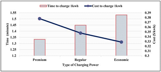
Figure 1.
Required time and cost to charge 1 kwh using smart charging.
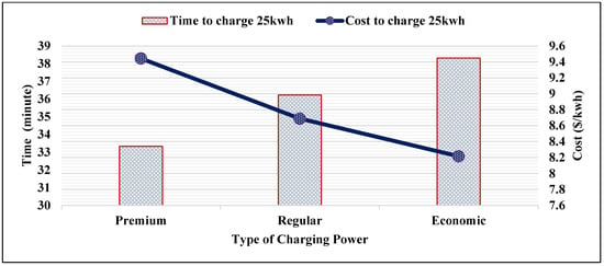
Figure 2.
Required time and cost to charge 25 kwh using smart charging.
6.2. Effect of Charging Power on Charging Duration and Charging Cost
The maximum charging duration and the corresponding charging costs are determined based on the following assumptions:
- The minimum state-of-charge of vehicles is [45,46].
- Given the battery safety considerations, the maximum state-of-charge using FCS is , as in [47].
- Given and , the maximum charging duration is determined as in Equation (37).
- The charging efficiency is 90%, as in [48,49].
- The Nissan Leaf is utilized to represent a vehicle with a small battery capacity, .
- The Chevy Bolt is utilized to represent a vehicle with a small battery capacity, .
- The Tesla Model S is utilized to represent a vehicle with a small battery capacity, .
The maximum per unit charging duration is determined by taking the difference between and . Given the battery capacity , , or and the charging type , , or , maximum charging durations and costs are obtained as in (29) and (37). Figure 3, Figure 4 and Figure 5 visualize the effect of the proposed smart charging method on vehicles with different battery capacities. It is noted that the charging duration and charging costs increase when the battery capacity increases.
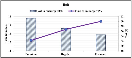
Figure 3.
Required time and cost to add 70% SOC into Bolt EV battery.
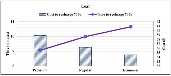
Figure 4.
Required time and cost to add 70% SOC into Leaf EV battery.
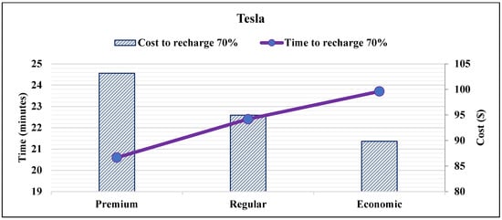
Figure 5.
Required time and cost to add 70% SOC into Tesla Model S battery.
6.3. Descriptive Statistics of Annual Data for Multiple FCSs
The per event annual energy profile for FCSs are obtained as in [44] and are described by maximum value, minimum value, and 25th, 50th, and 75th percentiles, as presented in Figure 6. The annual number of charging events occurs in FCSs, as presented in Figure 7. A clear variation among these annual profiles is depicted in Figure 6 and Figure 7.
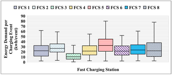
Figure 6.
A boxplot of the energy demand on the FCS per charging event in a year.
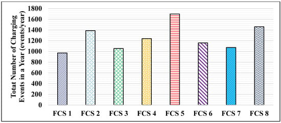
Figure 7.
Number of annual charging events for different FCSs.
6.4. Average Annual Energy Required from FCS
Given the per event energy profiles and the annual charging events for FCSs, the average energy profile and the average number of charging events for FCSs are obtained, as in Equations (44)–(49). Figure 8 depicts the per event energy profiles using the following values: the maximum and the minimum values as well as the three quartiles and percentiles. As explained previously, the average number of charging events () represents the annual number of charging events that may occur at the FCS. Given , the energy required by vehicles for each charging event from the FCS is not determined.
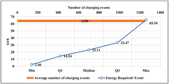
Figure 8.
Energy required per charging event and the average numbers of events.
In order to determine the annual energy required from the FCS in both extreme directions, the maximum () and minimum () values are utilized. The percentiles are utilized to quantitatively describe the annual energy required from the FCS. The average annual energy required from the FCS is obtained, as shown in Equations (50)–(54).
The reason for generating the average energy required from the FCS is to compute the annual costs of rebate and revenue. The annual cost of the rebate is a function of the smart charging penetration levels. Given the annual energy required from the FCS, different penetration levels of Ξ are considered, as presented in Table 3.

Table 3.
Maximum, minimum, and quantile annual energy required by different penetration levels of the proposed smart charging.
6.5. Fast Charging Station Annual Revenue and Rebate
Figure 9, Figure 10, Figure 11, Figure 12 and Figure 13 present the annual rebate and revenue considering the different charging energy required from the FCS:
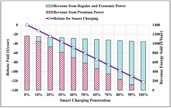
Figure 9.
Revenue and rebate of the minimum annual charging energy.
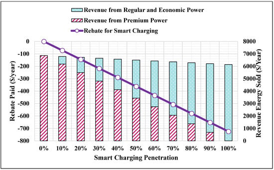
Figure 10.
Revenue and rebate of the 25th percentile annual charging energy.
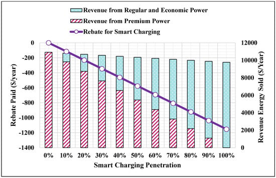
Figure 11.
Revenue and rebate of the median annual charging energy.
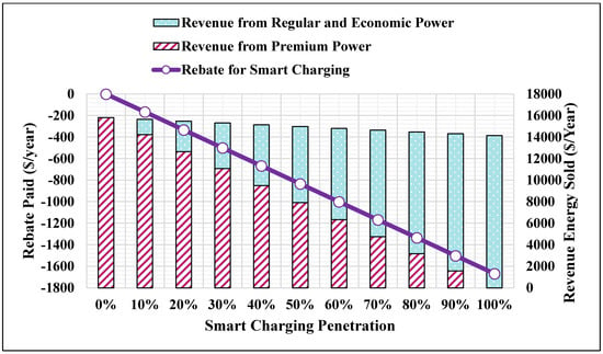
Figure 12.
Revenue and rebate of the 75th percentile annual charging energy.
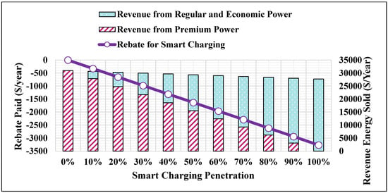
Figure 13.
Revenue and rebate of the maximum annual charging energy.
- The minimum annual charging energy (Figure 9) obtained as in (54);
- The 25th percentile annual charging energy (Figure 10) obtained as in (50);
- The 50th percentile annual charging energy (Figure 11) obtained as in (51);
- The 75th percentile annual charging energy (Figure 12) obtained as in (52);
- The maximum charging energy (Figure 13) obtained as in (53).
In each figure, the rebate represents the annual cost paid to the customer for using smart charging with regular and/or economic charging power. The annual rebate is shown in the right y-axis of each figure. The revenue is shown in the left y-axis of each figure and represents the costs obtained from selling the energy to customers when customers charge via premium , regular , and/or economic charging power. Each bar represents a result for a specific smart charging penetration level. For example, results of the first bar in Figure 9 is obtained as follows:
- Smart charging penetration is
- The costs of premium, regular, and economic charging powers as shown in Figure 1 are , , and ;
- The uniform random number determines the share of regular and economic power for each penetration level;
- The optimal factors for the premium , regular , and economic power are 1, 0.925 and 0.875.
then,
- the average minimum annual charging energy required from the FCS is ,
- the annual rebate and revenue are calculated as in Equations (55) and (65),
- the revenue of the smart charging is zero because , as well as the rebate ,
- thus, the revenue is calculated from selling the energy from using the premium power only, ,
- the ratio of the revenue to the rebate of using the smart charging is 9 and obtained by averaging optimal factors, and , and substituting the average into Equations (95) or (98).
By increasing , the rest of the bars in Figure 9 can be obtained. When , the revenue and rebate of using regular and economic charging power are determined by randomly assigned . The revenue and rebate of using smart charging are assigned by taking their average, individually, after multiple iterations (350 iterations) as recommended in [46]. From Figure 9, Figure 10, Figure 11, Figure 12 and Figure 13, it is noted that:
- The annual revenue changes slightly as the smart charging penetration levels increases. This means that as the revenue of using the premium power decreases; it is compensated by using the regular and economic charging powers. Therefore, the proposed smart charging method preserves the annual revenue.
- The rebate is increased as the smart charging penetration levels is increased (i.e., increased considering the same in Figure 9).
6.6. Cost Comparison of the Proposed Smart Charging Method and DSTATCOM
As per the utility general standard practice, if flicker complaints result from the operation of the customer’s equipment, the customer’s equipment shall be disconnected. From the viewpoint of the investor, the main benefit of flicker mitigation is to avoid the service disconnection from the facility. From the viewpoint of the operator, the benefit is to protect their equipment as well as nearby customers. When the operation of fast charging stations causes a voltage fluctuation and light flicker, the FCSs may get disconnected resulting in financial losses. The financial losses are represented by the FCS downtime. The downtime is the total amount of time that the FCS is not accessible. The FCS downtime and its losses can be interpreted as the cost of voltage flicker incurred by the FCS’s owner. In order to avoid FCS downtime, voltage fluctuation and light flicker should be mitigated. In Section 4, several flicker mitigation devices are analyzed and compared, based on different criteria. It was found that the cheapest mitigation device is the DSTATCOM, according to the cost per kVAr basis and the total annual equivalent cost. The total annual equivalent cost of DSTATCOM is 14,568 $/year. The proposed smart charging method in this study can also be utilized to mitigate the voltage fluctuation and light flicker. To make customers adopt the proposed smart charging method, an instant rebate is paid to the customer for each charging event from the FCS. The annual rebate can be interpreted as the annual cost incurred by the FCS to mitigate the light flicker, thereby avoiding financial losses due to the FCS downtime. The annual rebate is a function of the annual smart charging penetration level. Figure 14 shows the annual rebates of different penetration levels of the proposed smart charging method.
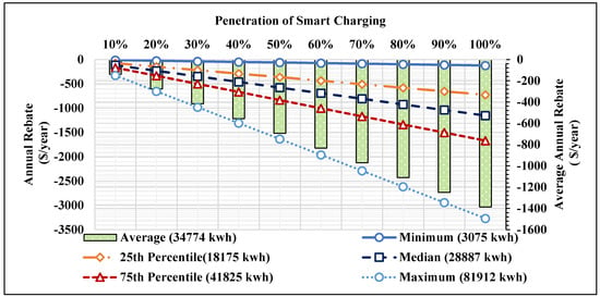
Figure 14.
Annual cost of the proposed smart charging.
As presented in Figure 14, the rebate is not only a function of the smart charging penetration level, but is also a function of the minimum, maximum, 25th, 50th, and 75th percentiles of annual energy required from the FCS. To compare the annual cost of smart charging with the annual cost of DSTATCOM, the annual average rebate of using smart charging is calculated. The annual average rebate is estimated by averaging the values of Equations (60) and (63). From Figure 14, it is noted that the average rebate increases from nearly $140 to $1400 as the smart charging penetration level increases from 10% to 100%. This means that the minimum annual cost incurred by the FCS when the proposed smart charging is applied is $140, whereas the maximum annual incurred cost by the FCS is $1400. Figure 15 represents the cost percentage decrease when the proposed smart charging method is utilized, in comparison to the cost of DSTATCOM. The annual cost of the proposed smart charging method is reduced by a minimum of 90% to a maximum of 99% of the cost of the DSTATCOM, in comparison to the annual cost of DSTATCOM. Figure 15 clearly shows that the proposed smart charging method achieves a tremendous reduction in the cost of mitigating voltage fluctuation and light flicker.
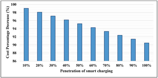
Figure 15.
Comparison of costs of the proposed smart charging and DSTATCOM.
7. Conclusions
A novel smart charging approach has been introduced lately in the literature, aiming to mitigate the impact of FCSs on voltage fluctuation and light flicker. The proposed charging method encompasses three different levels of charging powers, namely economic, regular, and premium. The research presented in this work has been devoted to proposing a cost of each charging power. The per unit regular and economic charging cost is modeled to be a function of the per unit cost of premium charging power and a scaling factor. A scaling factor is proposed to represent a rebate offered to the customer to adopt the regular and economic charging powers. The rebate is designed to compensate the increase in the charging duration by reducing the per unit cost of regular and economic charging power. The cost is modeled to preserve a balance in the required cost to charge 1 kwh by the regular or economic power to the required time to charge 1 kwh by the premium power. The ratio of time required by premium power to the time required by regular power is 0.92, whereas the ratio of the cost incurred by using premium power to regular power is 1.08. Similarly, the ratio of premium power to regular was found to be ±13%. Multiple penetration levels of smart charging, varying from 0% up to 100%, were considered and their corresponding annual rebate or revenue was estimated. Additionally, costs of several mitigation devices were quantified and compared. The results reveal that DSTATCOM is nominated, based on the cost per kVAr, to achieve the minimum total annual equivalent costs incurred by an FCS operator or investor to mitigate variation of voltage at the FCS. The annual cost of DSTATCOM is found to be 14,568 $/year. When the smart charging penetration levelis 10%, the annual cost incurred by an FCS operator or investor, by applying smart charging, is less than the annual cost of installing DSTATCOM by 99%. Nevertheless, even when smart charging penetration level is 100%, the annual cost incurred by an FCS operator or investor, by applying smart charging, is less than the annual cost of installing DSTATCOM by 90%. In future work, the time-of-use price can be included to design the proposed cost model of this study.
Funding
This research received no external funding.
Institutional Review Board Statement
Not applicable.
Informed Consent Statement
Not applicable.
Data Availability Statement
Not applicable.
Acknowledgments
Sami M. Alshareef would like to acknowledge the funding support received from Jouf University, Saudi Arabia, to conduct this study.
Conflicts of Interest
The author declares no conflict of interest.
Nomenclature
| The total annual equivalent cost, | |
| The annual equivalent cost of capital invested, | |
| The annual equivalent cost of maintenance, | |
| The first cost of installed flicker mitigation device, | |
| The estimated salvage value at the end of the device useful life, | |
| The capital recovery factor | |
| The single-payment discount factor | |
| The fixed charge rate, % | |
| The useful life in years (flicker mitigation device lifetime), years | |
| The cost per unit of installed flicker mitigation device, | |
| The salvage value per kvar at the end of , | |
| The operating range of the flicker mitigation device, | |
| The per unit cost of the unified power quality conditioner, | |
| The per unit cost of the distribution static compensator, | |
| The per unit cost of the thyristor switched capacitor, | |
| The per unit cost of the fixed capacitors/thyristor controlled reactors, | |
| The per unit cost of the dynamic voltage restorer, | |
| The per unit cost of the fixed series capacitor, | |
| The operating range of the unified power quality conditioner, | |
| The operating range of the distribution static compensator, | |
| The operating range of the thyristor switched capacitor, | |
| The operating range of the fixed capacitors/thyristor controlled reactors, | |
| The operating range of the dynamic voltage restorer, | |
| The operating range of the fixed series capacitor, | |
| The maintenance cost in percent of the first cost, (%) | |
| Number of electric vehicles in the system | |
| The maintenance cost of the unified power quality conditioner in % of first cost | |
| The maintenance cost of the distribution static compensator in % of first cost | |
| The maintenance cost of the thyristor switched capacitor in % of first cost | |
| The maintenance cost of the fixed capacitors/thyristor controlled reactors in % of first cost | |
| The maintenance cost of the dynamic voltage restorer in % of first cost | |
| The maintenance cost of the fixed series capacitor in % of first cost | |
| Efficiency of the fast charger, % | |
| Factor to convert hour into minutes | |
| Maximum charging power per port, kw | |
| Premium charging power, kw | |
| Regular charging power, kw | |
| Economic charging power, kw | |
| Factor to set the upper limits of premium charging power, % | |
| Factor to set the lower limits of premium charging power, % | |
| Factor to set the upper limits of regular charging power, % | |
| Factor to set the lower limits of regular charging power, % | |
| Factor to set the upper limits of economic charging power, % | |
| Factor to set the lower limits of economic charging power, % | |
| The time it takes to charge 1 kwh by premium power, | |
| The time it takes to charge 1 kwh by regular power, | |
| The time it takes to charge 1 kwh by economic power, | |
| The per unit cost of the premium charging, | |
| The per unit cost of the regular charging, | |
| The per unit cost of the economic charging, | |
| The per hour PBEV fast charging cost, | |
| The per minutes PBEV fast charging cost, | |
| The maximum cost of charging a BPEV from FCS, | |
| The per unit cost of fast charging, | |
| The maximum allowable SOC for any BPEV, | |
| The minimum allowable SOC for any BPEV, | |
| A percent to determine the maximum SOC, | |
| A percent to determine the minimum SOC, | |
| Capacity of a PBEV battery, | |
| Capacity of a small battery, | |
| Capacity of a medium battery, | |
| Capacity of a large battery, | |
| A set of PEVs with small battery capacity uses the FCS | |
| A set of PEVs with medium battery capacity uses the FCS | |
| A set of PEVs with large battery capacity uses the FCS | |
| The maximum time it takes a BPEV to be charged, from its minimum to its maximum state-of-charge, using FCS, | |
| The per unit time it takes to charge a BPEV, from its minimum to its maximum state-of-charge, using FCS, | |
| The 25th percentile of charging energy per charging event of FCS in a year, | |
| The 50th percentile of charging energy per charging event of FCS in a year, | |
| The 75th percentile of charging energy per charging event of FCS in a year, | |
| The maximum of charging energy per charging event of FCS in a year, | |
| The minimum of charging energy per charging event of FCS in a year, | |
| The average value of the first quartile of charging energy per charging event in a year, for number of FCSs, | |
| The average value of the second quartile of charging energy per charging event in a year, for number of FCSs, | |
| The average value of the third quartile of charging energy per charging event in a year, for number of FCSs, | |
| The average value of the maximum of charging energy per charging event in a year, for number of FCSs, | |
| The average value of the minimum of charging energy per charging event in a year, for number of FCSs, | |
| The maximum cost of charging a BPEV from FCS, | |
| The per unit cost of fast charging, | |
| The average number of annual charging events in number of FCSs, | |
| The number of annual charging events in FCS | |
| The estimated 25th percentile value of annual charging energy for a FCS, | |
| The estimated 50th percentile value of annual charging energy for a FCS, | |
| The estimated 75th percentile value of annual charging energy for a FCS, | |
| The estimated maximum value of annual charging energy for a FCS, | |
| The estimated minimum value of annual charging energy for a FCS, | |
| The 25th percentile annual rebate paid to customers for using smart charging power, | |
| The median annual rebate paid to customers for using smart charging power, | |
| The 75th percentile annual rebate paid to customers for using smart charging power, | |
| The maximum annual rebate paid to customers for using smart charging power, | |
| The minimum annual rebate paid to customers for using smart charging power, | |
| A uniform random number | |
| Share of PBEV that utilizes smart charging power at an FCS, | |
| The 25th percentile annual revenue from customers for using smart charging power, | |
| The median annual revenue from customers for using smart charging power, | |
| The 75th percentile annual revenue from customers for using smart charging power, | |
| The maximum annual revenue from customers for using smart charging power, | |
| The minimum annual revenue from customers for using smart charging power, | |
| Revenue from a customer when the regular charging power is utilized, | |
| Rebate paid to a customer when the regular charging power is utilized, | |
| Optimal factor to set the limit of premium charging power, | |
| Optimal factor to set the limit of regular charging power, | |
| Revenue from a customer when the economic charging power is utilized, | |
| Rebate paid to a customer when the economic charging power is utilized, |
References
- McKerracher, C. Electric Vehicle Outlook 2018. Bloomberg New Energy Finance. Available online: https://about.bnef.com/electric-vehicle-outlook/ (accessed on 4 April 2019).
- Sharma, I.; Canizares, C.; Bhattacharya, K. Smart Charging of PEVs Penetrating into Residential Distribution Systems. IEEE Trans. Smart Grid 2014, 5, 1196–1209. [Google Scholar] [CrossRef]
- Humayd, A.S.B.; Bhattacharya, K. Design of Optimal Incentives for Smart Charging Considering Utility-Customer Interactions and Distribution Systems Impact. IEEE Trans. Smart Grid 2017, 10, 1521–1531. [Google Scholar] [CrossRef]
- Moghaddam, Z.; Ahmad, I.; Habibi, D.; Phung, Q.V. Smart Charging Strategy for Electric Vehicle Charging Stations. IEEE Trans. Transp. Electrif. 2018, 4, 13. [Google Scholar] [CrossRef]
- van der Kam, M.; van Sark, W. Smart Charging of Electric Vehicles with Photovoltaic Power and Vehicle-to-Grid Technology in a Microgrid: A Case Study. Appl. Energy 2015, 152, 20–30. [Google Scholar] [CrossRef] [Green Version]
- Bin Humayd, A.S.; Lami, B.; Bhattacharya, K. The Effect of PEV Uncontrolled and Smart Charging on Distribution System Planning. In Proceedings of the IEEE Electrical Power and Energy Conference, Ottawa, ON, Canada, 12–14 October 2016; pp. 1–6. [Google Scholar] [CrossRef]
- Ma, T.-Y.; Xie, S. Optimal Fast Charging Station Locations for Electric Ridesharing with Vehicle-Charging Station Assignment. Transp. Res. Part D Transp. Environ. 2021, 90, 102682. [Google Scholar] [CrossRef]
- Mahfouz, M.M.; Iravani, R. Autonomous Operation of the DC Fast-Charging Station. IEEE Trans. Ind. Electron. 2022, 69, 3787–3797. [Google Scholar] [CrossRef]
- Zhang, W.; Zhao, H.; Song, Z. Integrating Transit Route Network Design and Fast Charging Station Planning for Battery Electric Buses. IEEE Access 2021, 9, 51604–51617. [Google Scholar] [CrossRef]
- Ding, X.; Zhang, W.; Wei, S.; Wang, Z. Optimization of an Energy Storage System for Electric Bus Fast-Charging Station. Energies 2021, 14, 4143. [Google Scholar] [CrossRef]
- Liu, X. Dynamic Response Characteristics of Fast Charging Station-EVs on Interaction of Multiple Vehicles. IEEE Access 2020, 8, 42404–42421. [Google Scholar] [CrossRef]
- Ardeshiri, A.; Rashidi, T.H. Willingness to Pay for Fast Charging Station for Electric Vehicles with Limited Market Penetration Making. Energy Policy 2020, 147, 111822. [Google Scholar] [CrossRef]
- Elma, O. A Dynamic Charging Strategy with Hybrid Fast Charging Station for Electric Vehicles. Energy 2020, 202, 117680. [Google Scholar] [CrossRef]
- Sun, B.; Dragičević, T.; Freijedo, F.D.; Vasquez, J.C.; Guerrero, J.M. A Control Algorithm for Electric Vehicle Fast Charging Stations Equipped With Flywheel Energy Storage Systems. IEEE Trans. Power Electron. 2016, 31, 6674–6685. [Google Scholar] [CrossRef] [Green Version]
- Gjelaj, M.; Traholt, C.; Hashemi, S.; Andersen, P.B. Cost-Benefit Analysis of a Novel DC Fast-Charging Station with a Local Battery Storage for EVs. In Proceedings of the 2017 52nd International Universities Power Engineering Conference (UPEC), Heraklion, Greece, 28–31 August 2017; pp. 1–6. [Google Scholar]
- Chen, H.; Hu, Z.; Zhang, H.; Luo, H. Coordinated Charging and Discharging Strategies for Plug-in Electric Bus Fast Charging Station with Energy Storage System. IET Gener. Transm. Distrib. 2018, 12, 2019–2028. [Google Scholar] [CrossRef] [Green Version]
- Deng, J.; Shi, J.; Liu, Y.; Tang, Y. Application of a Hybrid Energy Storage System in the Fast Charging Station of Electric Vehicles. IET Gener. Transm. Distrib. 2016, 10, 1092–1097. [Google Scholar] [CrossRef]
- Malik, F.H.; Lehtonen, M. Analysis of power network loading due to fast charging of Electric Vehicles on highways. In Proceedings of the 2016 Electric Power Quality and Supply Reliability (PQ), Tallinn, Estonia, 29–31 August 2016; pp. 101–106. [Google Scholar] [CrossRef]
- Amanor-Boadu, J.M.; Abouzied, M.A.; Sanchez-Sinencio, E. An Efficient and Fast Li-Ion Battery Charging System Using Energy Harvesting or Conventional Sources. IEEE Trans. Ind. Electron. 2018, 65, 7383–7394. [Google Scholar] [CrossRef]
- Celli, G.; Soma, G.G.; Pilo, F.; Lacu, F.; Mocci, S.; Natale, N. Aggregated Electric Vehicles Load Profiles with Fast Charging Stations. In Proceedings of the 2014 Power Systems Computation Conference, Wrocław, Poland, 18–22 August 2014; pp. 1–7. [Google Scholar] [CrossRef]
- Febriwijaya, Y.H.; Purwadi, A.; Rizqiawan, A.; Heryana, N. A Study on the Impacts of DC Fast Charging Stations on Power Distribution System. In Proceedings of the 2014 International Conference on Electrical Engineering and Computer Science (ICEECS), Kuta, Bali, Indonesia, 24–25 November 2014; pp. 136–140. [Google Scholar] [CrossRef]
- Alshareef, S.M. A Novel Smart Charging Method to Mitigate Voltage Fluctuation at Fast Charging Stations. Energies 2022, 15, 1746. [Google Scholar] [CrossRef]
- IRENA. Innovation Landscape Brief: Electric-Vehicle Smart Charging. 2019. Available online: https://www.irena.org/-/media/Files/IRENA/Agency/Publication/2019/Sep/IRENA_EV_Smart_Charging_2019.pdf?la=en&hash=E77FAB7422226D29931E8469698C709EFC13EDB2 (accessed on 7 June 2020).
- Pinto, R.J.C.; Pombo, J.; Calado, M.R.A.; Mariano, S.J.S. An Electric Vehicle Charging Station: Monitoring and Analysis of Power Quality. In Proceedings of the 2015 9th International Conference on Compatibility and Power Electronics (CPE), Costa da Caparica, Portugal, 24–26 June 2015; pp. 37–42. [Google Scholar] [CrossRef]
- Yunus, K.; Reza, M. Distribution Grid Impact of Plug-In Electric Vehicles Charging at Fast Charging Stations Using Stochastic Charging Model. In Proceedings of the 14th European Conference on Power Electronics and Applications, Birmingham, UK, 30 August–1 September 2011; p. 11. [Google Scholar]
- Li, Q.; Tao, S.; Xiao, X.; Wen, J. Monitoring and Analysis of Power Quality in Electric Vehicle Charging Stations. In Proceedings of the 2013 1st International Future Energy Electronics Conference (IFEEC), Tainan, Taiwan, 3–6 November 2013; pp. 277–282. [Google Scholar] [CrossRef]
- Alshareef, S.M.; Morsi, W.G. Impact of Fast Charging Stations on the Voltage Flicker in the Electric Power Distribution Systems. In Proceedings of the 2017 IEEE Electrical Power and Energy Conference (EPEC), Saskatoon, SK, Canada, 22–25 October 2017; pp. 1–6. [Google Scholar]
- Marei, M.I.; El-Saadany, E.F.; Salama, M.M. Envelope Tracking Techniques for FlickerMitigation and Voltage Regulation. IEEE Trans. Power Deliv. 2004, 19, 1854–1861. [Google Scholar] [CrossRef]
- Hock, R.T.; De Novaes, Y.R.; Batschauer, A.L. A Voltage Regulator for Power Quality Improvement in Low-Voltage Distribution Grids. IEEE Trans. Power Electron. 2018, 33, 2050–2060. [Google Scholar] [CrossRef]
- Molina, M.G.; Mercado, P.E. Control Design and Simulation of DSTATCOM with Energy Storage for Power Quality Improvements. In Proceedings of the 2006 IEEE/PES Transmission & Distribution Conference and Exposition, Latin America, Caracas, Venezuela, 15–18 August 2006; pp. 1–7. [Google Scholar] [CrossRef]
- Molina, M.G.; Mercado, P.E. Dynamic Modeling and Control Design of DSTATCOM with Ultra-Capacitor Energy Storage for Power Quality Improvements. In Proceedings of the 2008 IEEE/PES Transmission and Distribution Conference and Exposition, Latin America, Bogota, Colombia, 13–15 August 2008; pp. 1–8. [Google Scholar] [CrossRef]
- Electric Power Research Institute (EPRI). Guidebook on Custom Power Devices. 2000. Available online: https://www.epri.com/research/products/000000000001000340 (accessed on 4 January 2020).
- Mathur, R.M.; Varma, R.K. Thyristor-Based FACTS Controllers for Electrical Transmission Systems; Wiley-IEEE Press: New York, NY, USA, 2002. [Google Scholar] [CrossRef]
- Taher, S.A.; Afsari, S.A. Optimal Location and Sizing of UPQC in Distribution Networks Using Differential Evolution Algorithm. Math. Probl. Eng. 2012, 2012, 838629. [Google Scholar] [CrossRef]
- Marjani, S.R.; Talavat, V.; Galvani, S. Optimal Allocation of D-STATCOM and Reconfiguration in Radial Distribution Network using MOPSO Algorithm in TOPSIS Framework. Int. Trans. Electr. Energy Syst. 2019, 29, e2723. [Google Scholar] [CrossRef]
- Saravanan, M.; Slochanal, S.M.R.; Venkatesh, P.; Abraham, J.P.S. Application of Particle Swarm Optimization Technique for Optimal Location of FACTS Devices Considering Cost of Installation and System Loadability. Electr. Power Syst. Res. 2007, 77, 276–283. [Google Scholar] [CrossRef]
- Moghadasi, A.; Sarwat, A.; Guerrero, J. A Comprehensive Review of Low-Voltage-Ride-through Methods for Fixed-Speed Wind Power Generators. Renew. Sustain. Energy Rev. 2016, 55, 823–839. [Google Scholar] [CrossRef] [Green Version]
- Hosseinpour, M.; Yazdian, A.; Hohamadian, M.; Kazempour, J. Desing and Simulation of UPQC to Improve Power Quality and Transfer Wind Energy to Grid. J. Appl. Sci. 2008, 8, 3770–3782. [Google Scholar] [CrossRef]
- Somsai, K.; Kulworawanichpong, T. Cost Estimation for Reactive Power Compensation in Distribution Power System by using D-STATCOM. Available online: http://www.i-asem.org/publication_conf/anbre13/M3D.4.ER655_1199F.pdf (accessed on 7 January 2020).
- Milanovic, J.; Zhang, Y. Global Minimization of Financial Losses Due to Voltage Sags With FACTS Based Devices. IEEE Trans. Power Deliv. 2010, 25, 298–306. [Google Scholar] [CrossRef]
- McGranaghan, M.; Roettger, B. Economic Evaluation of Power Quality. IEEE Power Eng. Rev. 2002, 22, 8–12. [Google Scholar] [CrossRef]
- Arrillaga, J.; Liu, Y.H.; Watson, N.R. Flexible Power Transmission; John Wiley & Sons: Chichester, UK, 2007. [Google Scholar] [CrossRef]
- C. Electrique Inc. 50 kW Fast-Charge Station. The Electric Circuit. Available online: https://lecircuitelectrique.com/en/cost/ (accessed on 20 April 2022).
- evCloud | FleetCarma. Available online: https://www.fleetcarma.com/evCloud (accessed on 19 December 2018).
- Hajimiragha, A.; Canizares, C.A.; Fowler, M.W.; Elkamel, A. Optimal Transition to Plug-in Hybrid Electric Vehicles in Ontario, Canada, Considering the Electricity-Grid Limitations. IEEE Trans. Ind. Electron. 2009, 57, 690–701. [Google Scholar] [CrossRef]
- Bin Humayd, A. Distribution System Planning in Smart Grids to Accommodate Distributed Energy Resources and Electric Vehicles. University of Waterloo, 2017. Available online: https://uwspace.uwaterloo.ca/bitstream/handle/10012/12049/BinHumayd_Abdullah.pdf?sequence=3&isAllowed=y (accessed on 11 November 2019).
- Gjelaj, M.; Traeholt, C.; Hashemi, S.; Andersen, P.B. DC Fast-Charging Stations for EVs Controlled by a Local Battery Storage in Low Voltage Grids. In Proceedings of the 2017 IEEE, Manchester PowerTech, Manchester, UK, 18–22 June 2017; pp. 1–6. [Google Scholar]
- Genovese, A.; Ortenzi, F.; Villante, C. On the Energy Efficiency of Quick DC Vehicle Battery Charging. World Electr. Veh. J. 2015, 7, 570–576. [Google Scholar] [CrossRef] [Green Version]
- Saberbari, E.; Saboori, H. Evaluating PHEV Impacts on Domestic Distribution Grid in Terms of Power Losses and Voltage Drop. In Proceedings of the 2014 19th Conference on Electrical Power Distribution Networks (EPDC), Tehran, Iran, 6–7 May 2014; pp. 52–58. [Google Scholar] [CrossRef]
Publisher’s Note: MDPI stays neutral with regard to jurisdictional claims in published maps and institutional affiliations. |
© 2022 by the author. Licensee MDPI, Basel, Switzerland. This article is an open access article distributed under the terms and conditions of the Creative Commons Attribution (CC BY) license (https://creativecommons.org/licenses/by/4.0/).