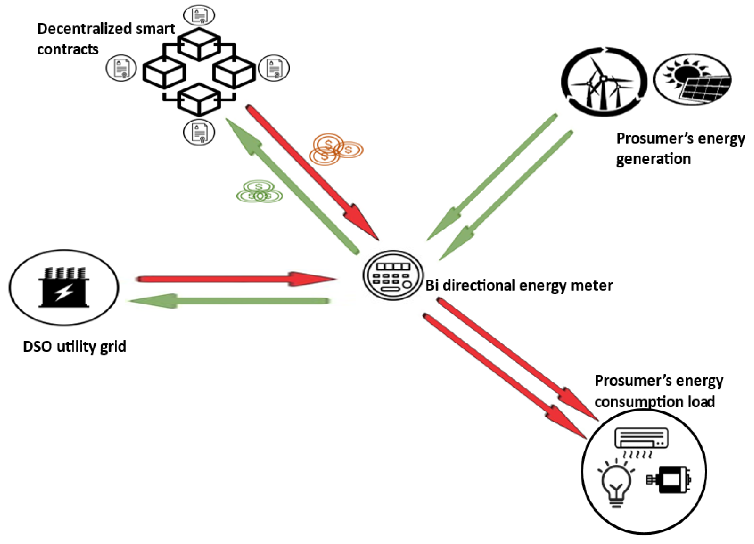
PoL is significant in all applications when services can be claimed according to the origin of the request location. This is the case in blockchain-based energy applications, as tokens are delivered only if requested by the corresponding certified smart meter deployed at a specific fixed and known location. The PoL scheme is detailed in full in this subsection. First, all entities involved in the system architecture are introduced. Next, the model architecture and the PoL setting procedure are explained. Finally, we describe how all the security vulnerabilities in setting a reliable PoL are closed by the threat and trust model of the proposed design.
4.2. PoL Primary Model Architecture
4.2.1. Definition of Geographic Ranges for Prover and Target Nodes
As the location of the target node is determined by trilateration based on the time difference of the arrival of a transmitted RF signal, both the target and its assigned prover nodes must be in close proximity to ensure the accuracy of the calculated position. For this purpose, appropriate geographic square zones are defined that cover the entire area of interest and have no overlap. The geographic areas, as well as the coordinates where the target nodes should be located, are defined in the location verifier smart contract. Each target node i, denoted , is an object consisting of: a location represented by two coordinates , and a particular geographic area , where: , where a and b are the area boundaries, and a is a set of potential prover nodes and selected prover nodes. Each node can apply to be an anchor in a permission-free manner by submitting its exact location coordinates to the location verifier smart contract and is accordingly connected to the corresponding target nodes via a mapping. Even if the location of a particular target node in the verifier smart contract is calculated relative to the provers’ claimed position, prover nodes in the proposed system cannot afford to lie about their position and would have to constantly update it in the location verifier smart contract. Any misstatement of position would adversely affect to the prover in question. This will become clearer as the paper progresses.
4.2.2. Location Verification Process
The target nodes of the proposed P2P energy trading system are smart meter nodes configured to monitor prosumers’ energy contributions to the power grid, requesting tokens when the associated prosumer delivers the corresponding energy. Because the private key needed to sign transactions is contained in the source code running on these nodes, anyone who gains access to the node’s source code can access the private key. This makes the system vulnerable to identity theft, especially by the consumer to whom the smart meter is assigned. Consequently, transactions generated by the aforementioned target nodes must include a PoL to interact with the smart contract responsible for granting tokens to prosumers in accordance to their energy aggregation. Although location is not an absolute proof of identity, a PoL provides more security alternatives to the system.
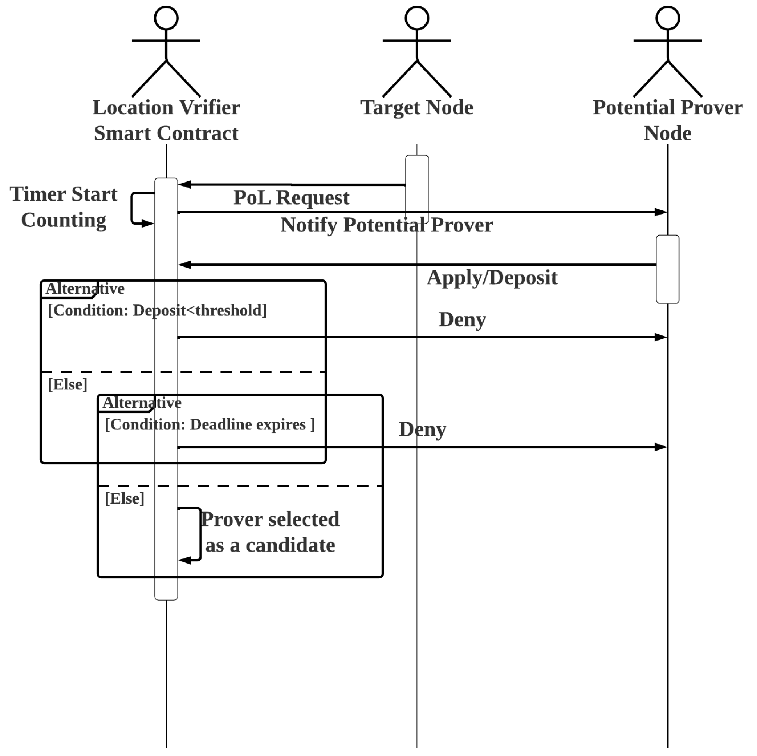
Once a suspected fraudster linked with a particular target node is identified, proof of its dishonest act can be found in the public ledger, which contains transactions associated with the transmission of data to the blockchain that is incompatible with the smart meter readings in question. A target node sends a request to the location verifier smart contract before sending the aforementioned transactions to the corresponding smart contract. The location verifier smart contract then sends an event to notify the potential registered prover nodes in the same area as the target node in question. To be considered for participation in the target node’s location verification process and potentially obtain a financial reward, interested prover nodes must make a deposit of at least a specific threshold. It is proposed to set a time limit for the submission of an application for a prover node and to stop accepting applications after the time limit expires. In such an application, a timer function with a specified time limit and a callback function are usually used. The callback function is automatically called when the selected time period ends, and the timer is triggered each time it is called. However, in most cases, implementing timers in a smart contract requires the use of an oracle, which means that the timers are implemented off-chain. The function to trigger the smart contract’s timer is implemented on-chain. When the set time expires, an event is triggered to notify the associated off-chain timer application, which in turn invokes the callback function in the smart contract.
However, as there is no callback function in our context, the desired on-chain timer application is applicable. When a target node makes a new request for a location trace, the timer starts counting. This also triggers an event that notifies registered provers in the same geographic area that they can apply to be PoL verifier nodes for the target node’s specific request. As the smart contract may receive overlapping or concurrent PoL requests from different target nodes, each target node has its own assigned timer. New prover applications are not accepted after the timer expires. The pseudocodes of Algorithm 2 and the flowchart in
Figure 2 show how this is implemented in the location verifier smart contract.
| Algorithm 2 Location Verifier Smart Contract: RequestPoL, Apply/Deposit |
- 1:
Address: TargetNode - 2:
Uint: DepositThreshold - 3:
Uint: TimerDeadLine - 4:
Mapping: Address → Address[]: TargetNodePotenialProvers - 5:
Mapping: Address → Uint: PoLRequestId - 6:
Mapping: Address → Address[]: TargetNodeCandidateProvers - 7:
Mapping: Address → Uint: ProverDepositBalance - 8:
Mapping: Address → Uint: Timer - 9:
Procedure RequestPoL - 10:
Timer(msg.sender) ← Time.Now() - 11:
PoL(msg.sender) ← Time.Now() - 12:
emit event: ProversApplicationOpen - 13:
End Procedure - 14:
Procedure Payable Apply/Deposit(TargetNode) - 15:
Timer ← Timer(TargetNode) - 16:
If msg.value ≥ DepositThreshold Then - 17:
Revert() - 18:
End If - 19:
If Time.now() − Timer ≤ TimerDeadLine Then - 20:
TargetNodeCandidateProvers(TargetNode).push(msg.sender) - 21:
ProverDepositBalance(msg.sender) ← msg.value - 22:
Else - 23:
Emit Event: NotifyTargetNode(TargetNodeCandidateProvers) - 24:
End If - 25:
End Procedure
|
The random selection of provers among the candidates begins whenever a new prover application is denied.
4.2.3. Provers Random Selection
The random selection of the provers reduces the likelihood of collusion by reducing the probability that verifiers know each other. However, it must be based on an unpredictable random number generated by the location verifier smart contract. The generation of a random number by a smart contract, in contrast, is less obvious. There are only three approaches for generating random numbers with a smart contract. The first approach is to use the current block hash, block hash size, or current difficulty, which is determined by the block mining throughput. However, miners have a high degree of control over all of these parameters. In fact, it is the miners who calculate the block hash, and they might collude to mine blocks with a desired throughput, making this approach risky and the generated random number predictable. The second option is to have the random number generated outside of the smart contract by an oracle. This approach, however, is purely centralized and goes against the spirit of decentralization of the blockchain. It keeps a loophole open for bribed, corrupt central entities, especially if the generation of the random number has a financial incentive, as in our case. The last and most popular option is to use oracle-based verifiable random functions (VRF). The argument of the VRF oracle is that it cannot predict when the smart contract in question will request a random number. Therefore, it uses the timestamp of the request to generate a random number using an unpredictable but verifiable random function, which it then sends to the smart contract along with the proof of random generation. The VRF is made up of three different functions. They are, respectively: . The VRF must satisfy three conditions, namely:
Uniquenes: ∃.
Pseudo-randomness: Given a set of n inputs and their respective set of output , there is no pattern linking outputs together.
Provability:
The first function generates a Public/Secret key
and
based on the seed input
x. The second function generates a random output from the seed input and
; the third function is a proof of the correctness of
, which can be verified using the output
y and
. Although VRF is a proven random number generation method in today’s smart contracts [
31,
32], it is not appropriate for our application because it also relies on a smart contract-generated seed that is not random and can be manipulated. Although the three basic random number generation methods did not seem suitable for our proposed scheme, a thorough review of the literature led us to a model that did. The authors in [
33] presented a roulette game implemented with a smart contract. Players wager a certain number of tokens on a number and win if their chosen number comes up in the smart contract’s lucky draw. A game owner sells the tokens to the players and takes them back if the players lose, similar to casino roulette.
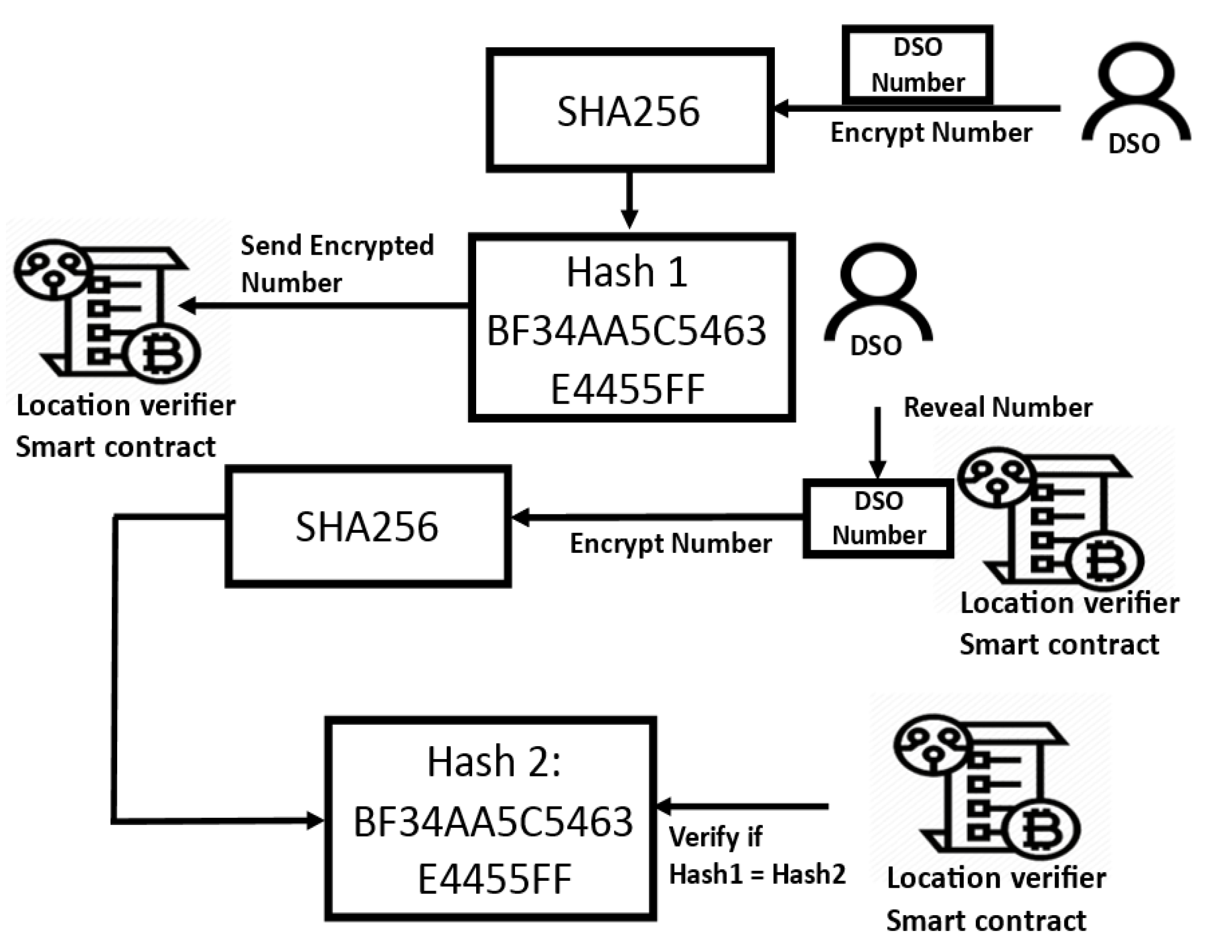
As the game owner and the player are counter-parties who would never collude, the game owner selects a random number, encrypts it, and sends it first to the smart contract in charge of the draw; after both the game owner’s and the player’s numbers are committed to the blockchain’s public ledger, the game owner decrypts the number. Using the owner’s public key, the smart contract checks whether the revealed number matches the encrypted number. If it does, it generates a random number using both the player and owner numbers. The owner starts first to ensure that he cannot manipulate the final result, and neither can the player, as the owner’s number is revealed only after the player has committed his number to the blockchain. This scheme ensures fully decentralized random number generation in an application with counter-parties (cannot collude). The DSO is the entity in the proposed architecture for which the exact locations of the target nodes are important.
As the DSO provides the tokens and grants them to the target nodes through energy aggregation, other nodes might be tempted to falsify the computed location to obtain the tokens without satisfying the agreed conditions. Because the tokens are used to pay the DSO for power consumption, the reliability of the system is of paramount importance to the DSO. Thus, the proposed system is similar to a roulette game where the DSO is the owner of the game and the prover nodes are the players. For this reason, we chose to use the same random number generation as implemented in [
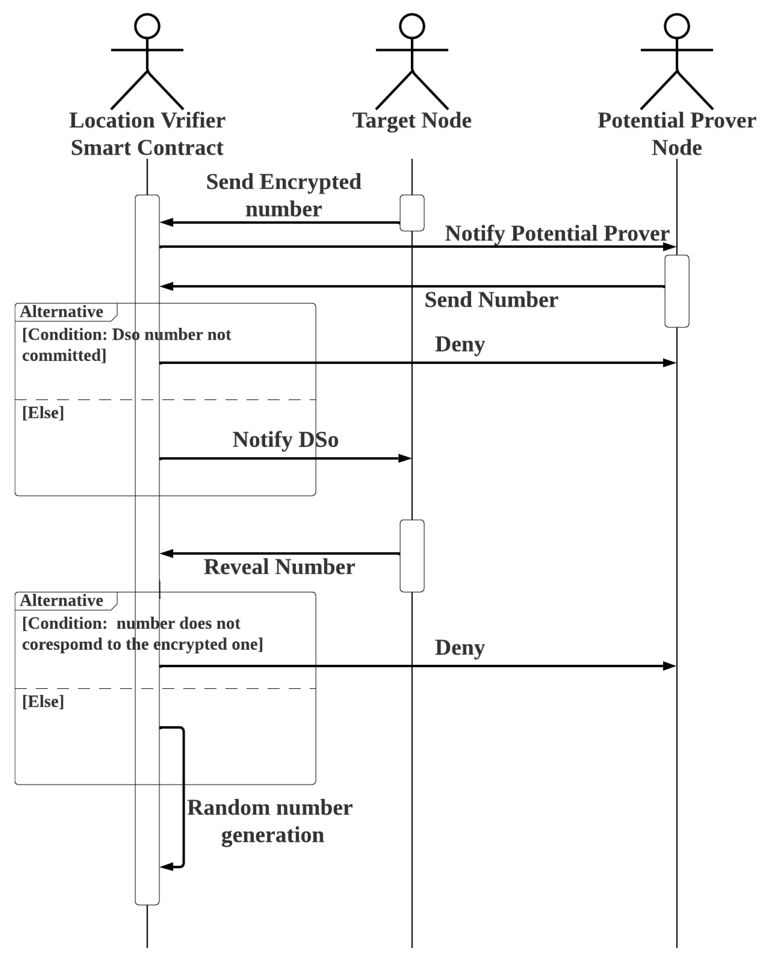
33]. Having its public key stored in the smart contract, the DSO starts the process by sending an encrypted number of its choice. Only after the DSO transaction is committed to the blockchain ledger can the prover node candidates send their own number to the blockchain, and the prover node candidates agree on the sink node that transmits their picked number with their respective signature. However, because identification in a permissionless blockchain environment is pseudo-anonymous, DSO can introduce covert nodes that use unknown public keys to manipulate the numerical sequence of prover candidates. For this reason, the sink node responsible for transmitting the prover number sequence should be an identified non-DSO node, such as a registered prosumer. The sink node would be the last prover to add a number to the sequence of numbers transmitted to the smart contract. After the numbers are committed to the blockchain and the corresponding signatures are verified, the DSO reveals its number, which is verified by the smart contract. If it matches the encrypted message, both the DSO and prover numbers are used by the smart contract to randomize the prover. See
Figure 3 for how the encrypted DSO number is revealed and verified.
The functions of the smart contract involved in random number generation are explained using the pseudocode of Algorithm 3 and the flowchart in
Figure 4.
Random number generation is used for random selection of the prover. The function in question is described in pseudocode in Algorithm 4.
| Algorithm 3 Location Verifier Smart Contract: SendDsoEncryptedNumber, SendProversNumber, DsoRevealNumber |
- 1:
Address: DSO - 2:
Mapping: Address → Uint: DsoSeedNumber - 3:
Mapping: Address → Uint: NonDsoSeedNumber - 4:
Mapping: Address → Bytes32: EncryptedDsoNumber - 5:
Procedure DsoSendEncryptedNumber(Bytes32 EncryptedNumber, AddressTargetNode) - 6:
EncryptedDsoNumber(TargetNode)← EncryptedNumber - 7:
Bool DsoNumberCommitted← True - 8:
emit event: NotifyProversToSendTheirNumber - 9:
End Procedure - 10:
Procedure SendProversNumber(UintNumber, AddressTargetNode) - 11:
If DsoNumberCommitted = True Then - 12:
NonDsoSeedNumber(TargetNode)← Number - 13:
BoolProversNumberCommitted← True - 14:
Emit Event: NotifyDsoToRevealNumber - 15:
Else - 16:
Revert() - 17:
End If - 18:
End Procedure - 19:
Procedure DsoRevealNumber(UintNumber, Address TargetNode) - 20:
If ProversNumberCommitted = True Then - 21:
EncryptedDsoNumber ← EncryptedDsoNumber(TargetNode) - 22:
c ← keccak256(abi.encode(Number)) - 23:
If c = EncryptedDsoNumber then - 24:
DsoSeedNumber(TargetNode)← Number - 25:
Else: - 26:
Revert( ) - 27:
End If - 28:
Else - 29:
Revert() - 30:
End If - 31:
End Procedure
|
| Algorithm 4 Location Verifier Smart Contract: SelectProvers |
- 1:
Mapping: Address → Address[]: TargetNodeCandidateProvers - 2:
Mapping: Address → Address[]: TargetNodeSelectedProvers - 3:
Mapping: Address → Uint: DsoSeedNumber - 4:
Mapping: Address ← Uint: NonDsoSeedNumber - 5:
Procedure SelectProvers(Address TargetNode) - 6:
Uint: DsoNumber ← DsoSeedNumber(TargetNode) - 7:
Uint: ProversNumber ← NonDsoSeedNumber(TargetNode) - 8:
i← 1 - 9:
while i ≤ TotalNumberOfSelectedProvers - 10:
k← keccak256(abi.encode(DsoNumber, ProversNumber, i)) % 6 - 11:
Prover ← TargetNodeCandidateProvers(TargetNode)[k] - 12:
if Prover ∉ TargetNodeSelectedProvers(TargetNode) then - 13:
TargetNodeSelectedProvers(TargetNode).push(Prover) - 14:
End If - 15:
i → i + 1 - 16:
End While - 17:
Emit Event: NotifyTargetNodeOfItsSelectedProvers(TargetNodeSelected-textProvers(TargetNode)) - 18:
End Procedure
|
4.2.4. Target Node Position Determination
The location verifier contract notifies the target node of its assigned prover after the prover nodes have been assigned. The target node, in turn, sends a RF message to each prover assigned to it, and each prover replies with the distance separating it from the target node calculated using TDoA. Before sending it back to the target node, each prover node signs the distance it has calculated. The location verifier smart contract verifies the signed distances received by the target node from the provers. Trilateration is used in TDoA localization to calculate the position of the target node based on the distances between the target node and at least three anchor nodes with known positions. However, three distances from three separate anchor nodes are sufficient to position the target node by solving the formula for the set of three equations, given a target node with coordinates
and three anchor nodes, where the coordinates of each anchor
i are
and
is the distance between the target node and each anchor
i.
As there are six selected anchor nodes, the target positioning can be done twice. After the six calculated distances are sent to the smart contract for location verification, the smart contract randomly selects two groups of three anchors to derive the target position by trilateration using the two randomly selected anchor groups. The DSO and the prover nodes are involved in the random selection based on the same random number generation discussed earlier. Following the pseudocode described in Algorithm 5, the two positions calculated using the selected anchor node groups are determined.
| Algorithm 5 Location Verifier Smart Contract: ComputetTargetNodePosition |
- 1:
Structure: Position - 2:
Uint: x1 - 3:
Uint: y - 4:
End Structure - 5:
Structure: ComputedDistance - 6:
Address: Prover - 7:
Uint: d - 8:
End Structure - 9:
Structure: PositionEquationParameters - 10:
Uint: AnchorNodeXPosition - 11:
Uint: AnchorNodeYPosition - 12:
Uint: Distance - 13:
End Structure - 14:
Mapping: Address → Position: NodePosition - 15:
Mapping: Address → ComputedDistance[6] TargetNodeComputed-Distances - 16:
Procedure
ComputeTargetNodePosisition(Address TargetNode) Returns Position P1, P2 - 17:
PositionEquationParameters DistanceEquation - 18:
PositionEquationParameters[2][3] DistanceEquations - 19:
Uint[]: AlreadyPicked - 20:
i ← 1 - 21:
nonce ← 1 - 22:
While i≤ 2 - 23:
j ← 1 - 24:
While j ≤ 3 - 25:
k← keccak256(abi.encode(DsoNumber2, ProversNumber2, nonce))% 6 - 26:
If k ∉ AlreadyPicked - 27:
AlreadyPicked.push(k) - 28:
c ← TargetNodeComputedDistance(TargetNode)[k] - 29:
DistanceEquation.Distance← c.d - 30:
x ← NodePosition(c.Prover).x - 31:
DistanceEquation.TargetNodeXPosition← x - 32:
y ← NodePosition(c.Prover).y - 33:
DistanceEquation.TargetNodeYPosition→ y - 34:
j ← j + 1 - 35:
nonce ← nonce+1 - 36:
DistanceEquations[i − 1][j− 1].push(DistanceEquation) - 37:
Else - 38:
nonce ← nonce+1 - 39:
End If - 40:
End While - 41:
i ← i + 1 - 42:
End While - 43:
Position P1, P2 - 44:
P1 → slove(DistanceEquations[0]) - 45:
P2 → slove(DistanceEquations[1]) - 46:
Return P1,P2 - 47:
End Procedure
|
Provers are rewarded in proportion to their stake if the two calculated points match; otherwise, they lose their stake. The calculated position of the target node is then compared to its legitimate position. The target node is an identity thief if the two positions do not match; otherwise, the transaction is accepted. Assume that the six selected provers have no prior knowledge of each other and do not collude, and each computes the distance between itself and the target node. If one of the nodes delivers an incorrect distance, the two locations estimated by the smart contract verifier will have different coordinates, causing all verifiers to lose their bet. Therefore, if the prover wants to participate in location verification, the specified coordinates of the prover nodes in the smart contract must be correct and they must invest in the implementation of the agreed network communication protocol and media standard required for TDoA positioning. However, regardless of the anchor-node combination used, trilateration positioning will always result in the same derived point if all six prover nodes decide to collude and agree on a specific target position, and if they all send the distance that separates them from the agreed incorrect target position. As a result, this scheme is ineffective against prover node collusion. In the next section, we will look at how game theory is used to effectively address challenges. To solve the three expressions of Equation (
1), we can expand the squares in each expression as follows:
The second expression is then subtracted from the first, and the third expression is subtracted from the second in Equation (
2), yielding a system of two equations with two unknowns of the type:
whose solution is given in Equation (
4):
where:
4.3. Enhanced Anti Collusion PoL Using Game Theory
In blockchain-based energy scenarios, there are two parties with two conflicting goals. The DSO might be tempted to misrepresent a location by claiming that the request did not originate from the smart meter node location in order to deny the prosumer a legitimate token claim. The prosumer, in turn, might be tempted to falsely claim that its request originated from the smart meter location in order to illegitimately claim an energy token. This leads to a possible game-theoretic scenario, explained below. Suppose a target node with coordinates requests PoL, where its legitimate position as deployed and set by the DSO is , and the position of the destination node calculated by TDoA trilateration is . In the proposed system, the involved parties can be classified into three categories:
The parties for whom it is harmful if , but beneficial for them if , i.e., the DSO or other partners, because in the latter situation they could reject a legitimate prosumer’s request for a token and enjoy the free energy aggregation. However, if , and , they could deliver an energy token to a non-deserving node.
Parties that are harmed when and ; these are the prosumer nodes and their partners that might be tempted to maliciously seek the position , to obtain a free energy token without having to supply the energy countervalue.
Neutral parties who participate only for the financial reward.
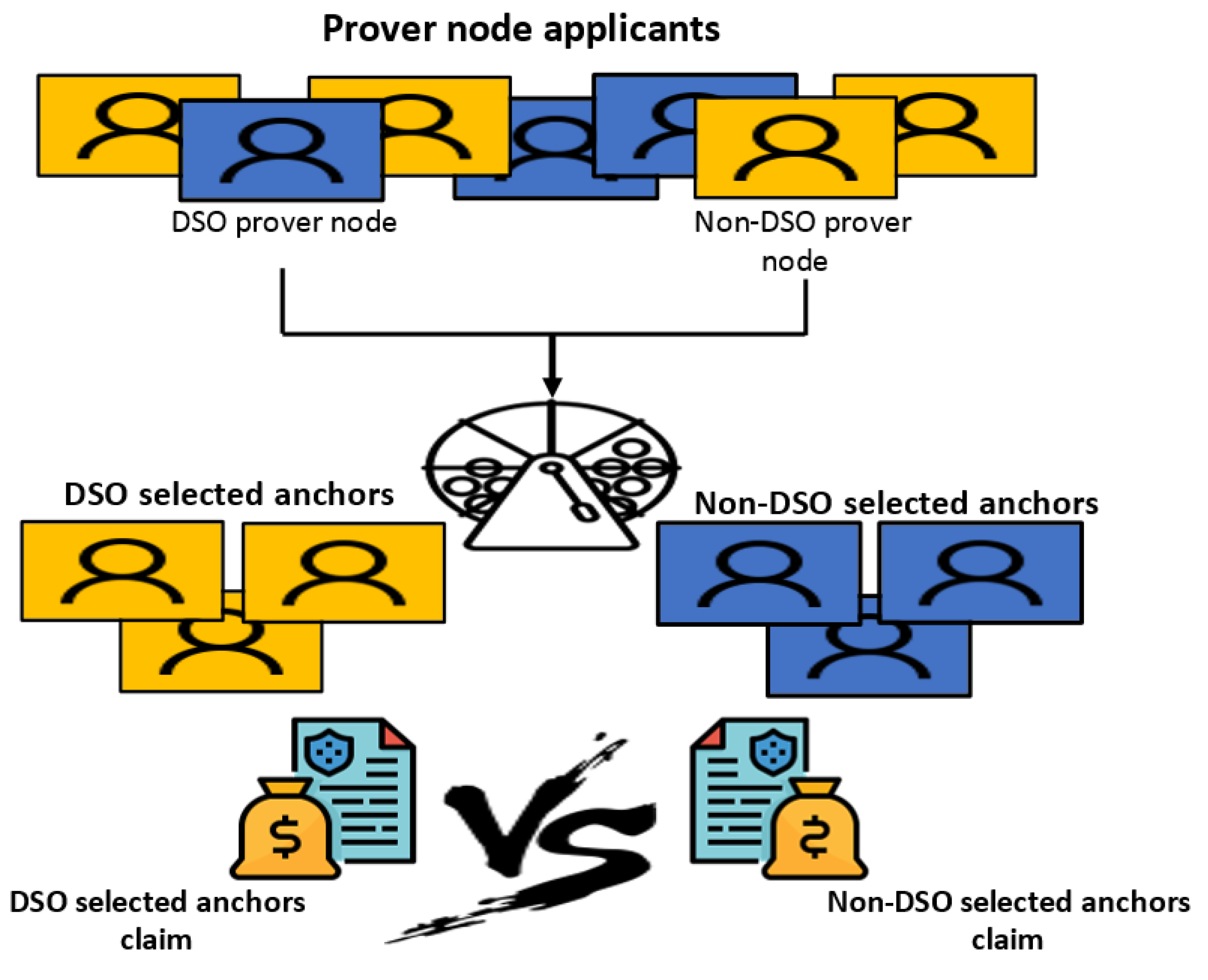
Because the system is permissionless, all parties can apply to be location provers. It is proposed that
N DSO prover nodes be defined in the smart contract, identified by their respective addresses. For prover applications, both DSO and non-DSO prover nodes are given fair slots, i.e., instead of a time-limited application, applications are open until a certain number
m of applicants is reached, where
applications are allowed for non-DSO nodes and
for DSO nodes. Similar to the PoL scheme above, six examiners are randomly selected from the set of
m, but there must be three DSO prover nodes and three non-DSO prover nodes. The function responsible for the random selection of examiners in this extended scheme is shown in the pseudocode of Algorithm 6. The distances asserted by the checkers must be sent to the smart contract in encrypted form. They can only be decrypted after they have all already been submitted to the blockchain.
| Algorithm 6 SelectRandomProvers |
- 1:
Uint: NumberofProverApplicants - 2:
Mapping: Address → Uint: DsoSeedNumber - 3:
Mapping: Address → Uint: NonDsoSeedNumber - 4:
Address[NumberofProverApplicants/2]: NonDsoProverNodes - 5:
Mapping(NumberofProverApplicants/2: NonDsoProverNodes - 6:
Procedure
ToggleBool(Bool b) - 7:
If b = True Then - 8:
b ← False - 9:
Else - 10:
b ← True - 11:
End Procedure - 12:
Procedure
SelectRandomProvers(Address TargetNode) - 13:
Bool DsoProverTurn← True - 14:
i ← 1 - 15:
While i ≤ 6 - 16:
DsoNumber2← DsoSeedNumber(TargetNode) - 17:
ProversNumber2← NonDsoSeedNumber(TargetNode) - 18:
k← keccak256(abi.encode(DsoNumber2, ProversNumber2, i)) % (m/2) - 19:
If DsoProverTurn = True Then - 20:
Prover ← DsoProverNodes[k] - 21:
If Prover ∉ TargetNodeSelectedProvers(TargetNode) then - 22:
TargetNodeSelectedProvers(TargetNode).push(Prover) - 23:
End If - 24:
ToggleBool(DsoProverTurn) - 25:
Else - 26:
Prover ← NonDsoProverNodes[k] - 27:
If Prover ∉ TargetNodeSelectedProvers(TargetNode) then - 28:
TargetNodeSelectedProvers(TargetNode).push(Prover) - 29:
End If - 30:
ToggleBool(DsoProverTurn) - 31:
End If - 32:
i ← i + 1 - 33:
End While - 34:
End Procedure
|
After the six encrypted distances are committed, they are decrypted and output by the respective prover nodes. Two target position points are derived by the location verifier smart contract. One is calculated using the three distances given by the DSO prover nodes, and the second is calculated using the distances given by the non-DSO prover nodes, according to the pseudocode in Algorithm 7.
| Algorithm 7 Location Verifier Smart Contract: ComputeTargetNodePosition |
- 1:
Structure: Position - 2:
Uint: x - 3:
Uint: y - 4:
End Structure - 5:
Structure: PositionEquationParameters - 6:
Uint: AnchorNodeXPosition - 7:
Uint: AnchorNodeYPosition - 8:
Uint: Distance - 9:
End Structure - 10:
Mapping: Address → Position: NodePosition - 11:
Mapping: Address → Uint[6]: TargetNodeComputedDistances /*The 3 first distances correspends to distances computed by DSO anchors, the rest by Non DSO anchors*/ - 12:
Procedure ComputeTargetNodePosisition(Address TargetNode) Returns Position P1, P2 - 13:
PositionEquationParameters DistanceEquation - 14:
PositionEquationParameters[2][3] DistanceEquations - 15:
i ← 1 - 16:
While i ≤ 2 - 17:
j ← 1 - 18:
While j ≤ 3 - 19:
d ← TargetNodeComputedDistances(TargetNode)[j − 1] - 20:
DistanceEquation.Distance← d - 21:
Prover ← TargetNodeSelectedProvers(TargetNode)[j − 1] - 22:
x ← NodePosition(Prover) - 23:
DistanceEquation.TargetNodeXPosition← x - 24:
y ← NodePosition(Prover).y - 25:
DistanceEquation.TargetNodeYPosition← y - 26:
DistanceEquations[i−1][j−1].push(DistanceEquation) - 27:
j ← j + 1 - 28:
End While - 29:
i ← i + 1 - 30:
End While - 31:
Position P1, P2 - 32:
P1 → slove(DistanceEquations[0]) - 33:
P2 → slove(DistanceEquations[1]) - 34:
Return P1,P2 - 35:
End Procedure
|
Note that the only case in which DSO prover nodes can be tempted to lie is when the target coordinates
, if the target coordinates claimed by the DSO nodes
, this must be true, whereas non-DSO prover nodes can only be tempted to lie about the position of the target node by claiming
. If the target coordinates computed by the non-DSO nodes are
, this must be true. This allows game theory to be applied to this system, as shown in
Figure 5.
We assume that the target positions calculated by the smart contract based on the distances of the DSO and non-DSO providers are
and
, respectively. We can discern for both DSO and non-DSO prover nodes in which they Certainly Tell the Truth (CTT) or Certainty Lie (CL), or situations in which no judgement can be made but At Least One Certainly Lies (ALOC). These situations are presented in Equations (6) and (7) for DSO and non-DSO prover nodes, respectively.
Table 1 and
Table 2 illustrate gains for both DSO and non-DSO provers’ according to their adopted game strategy (Lie/Tell the truth).
To calculate the Nash equilibrium, we calculate the total gain for both entities in the two situations described in
Table 1 and
Table 2—when the entity lies and when it is truthful. For the non-DSO prover node, the total gain is 50 when it is truthful and −20 when it lies. For the DSO-prover node, the total gain is 30 if it is truthful and −60 if it lies. Although the non-DSO prover node has an advantage in this game, the Nash equilibrium for both parties is to be truthful. The proposed PoL procedure is secure and safe against prover-target collusion. As for target-target collusion, it is not a threat to the proposed P2P application, as any target-target collusion is irrelevant if it does not usurp the respective legitimate position of the smart meter.
After P1 and P2 are calculated by the location verifier smart contract corresponding to target position claimed by the DSO and non-DSO sets of anchors, respectively, the PoL for the particular target node request is set according to the pseudocode in Algorithm 8. After the PoL is computed, it must be included as a parameter in the
function noted in Algorithm 1. To verify the validity of the PoL passed by the caller in the
function, the ERC20 smart contract delivering the energy token checks the validity of the asserted PoL by first verifying that it was issued by the location verifier smart contract by calling a getter function that accesses the key-value mapping linking the destination node addresses to their most recently computed PoL. The latter must be identical to the one passed in the
function call. The ERC20 smart contract that issues the energy tokens must also verify that the PoL Id matches that of the
call. Both Ids are associated with the respective function caller by mapping. It should be noted that both Ids are constrained and can only be incremented when the appropriate function is called. Because there must be a PoL for each token claim, the two Ids must be identical. How the PoL is checked when a token is claimed is shown in the pseudocode in Algorithm 9.
| Algorithm 8 Location Verifier Smart Contract: SetPoL, GetNodePol |
- 1:
Structure: PoL - 2:
Uint: PoLRequestId - 3:
Position: P - 4:
End Structure - 5:
Mapping: Address → PoL: TargetNodePoL - 6:
Procedure SetPol(PcomputedByDsoAnchors, PcomputedByNonDsoAnchors) - 7:
PoL ProofOfLocation - 8:
P1 ← PcomputedByDsoAnchors - 9:
P2 ← PcomputedByNonDsoAnchors - 10:
P* ← NodePosition(TargetNode) - 11:
If P1=P2 Then - 12:
ProofOfLocation.P← P1 - 13:
ProofOfLocation.PoLRequestId← RequestId(TargetNode) - 14:
ElseIf P1 != P2 Then - 15:
If P1 != P* & P2 != P* Then - 16:
ProofOfLocation.P← P2 - 17:
ProofOfLocation.PoLRequestId← RequestId(TargetNode) - 18:
Else - 19:
Revert() /* The proof of location is not considered and need to be recomputed*/ - 20:
End If - 21:
End If - 22:
End Procedure - 23:
Procedure GetNodePol(AddressAddr) Returns (PoL) - 24:
Return TargetNodePoL(Addr) - 25:
End Procedure
|
| Algorithm 9 ERC20 Smart contract: Verify |
- 1:
Address: LocationVerifierSmartContractAddress - 2:
Mapping: Address → Position: TargetNodeDefinedPosition - 3:
ProcedureVerify(Pol L) Returns (Bool) - 4:
c ← CallLocationVerifierSmartContract(LocationVerifierSmartContractAddress) - 5:
l ← c.GetNodePol(msg.sender) - 6:
Id ← RequestId(msg.sender) - 7:
N ← TargetNodeDefinedPosition(msg.sender) - 8:
if (L = l & l.RequestId = Id & L.Position = N) Then - 9:
Return true - 10:
Else - 11:
Return false - 12:
End If - 13:
End Procedure
|
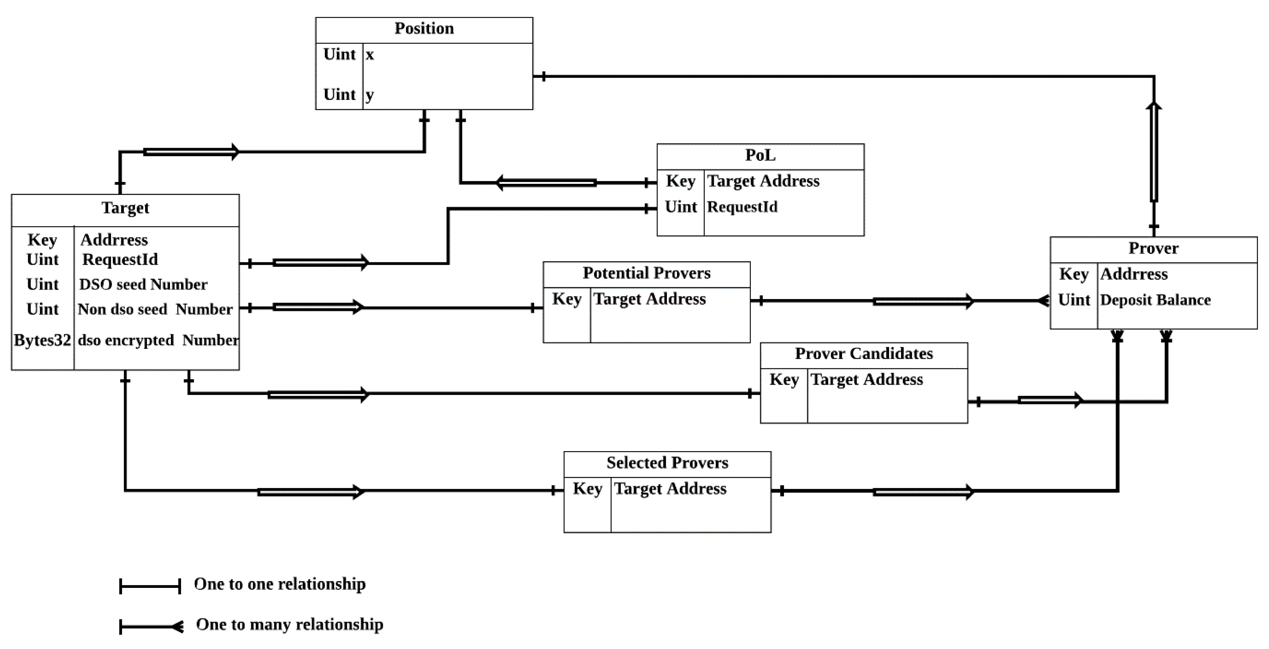
The entity diagram relationship in the proposed PoL scheme using the location verifier smart contract is described in
Figure 6.
Time Difference of Arrival
Time difference of arrival (TDoA), also known as multilateration, is a proven method for positioning RF transmitters. Using three or more anchor receivers, TDoA positions a signal source based on the difference in arrival times at the receivers. Before a round of TDoA positioning begins, both the target and its assigned anchor nodes must establish time synchronization. Here,
refers to the exact time at which the target sends a RF message to the respective anchor nodes. The distance between the anchor and the RF sender anchor node is calculated based on the time it takes for the RF message to reach the anchor node, as given in Equation (
8):
The time delay is determined using the cross-correlation in the time domain between the received signals at two anchors, which peaks when
, where
is the time delay between the two signals. Given a set of
n received signals
, each received at anchor i where
; Given a pair of sampled received signals
. Time delay at which the two signals are received is computed by time domain cross-correlation and is found according to Equation (
9):
where
Thus:
; where
is the target distance from anchor 1, and
is its distance from anchor 2. The hyperbola function of the distances between anchor nodes 1 and 2 and the target is given in Equation (
10):
However,
and
are both unknown, only
is known, which was derived according to Equation (
11):
To solve
, two more equations are needed. Thus, we need two more pairs of anchors and the time lag between their received signals. Therefore, this approach requires six anchor nodes to position the target node. However, there are other numerical methods that can be used to calculate the target position with fewer anchor nodes, such as in [
34].
The TDoA positioning accuracy is not really affected by the distance between the target node and the anchors, as TDoA is the positioning technique implemented by GPS localization and uses satellite anchors that are thousands of kilometers away from the target nodes. TDoA accuracy is mainly influenced by the quality of correlation, which depends on several factors:
The nature of the received RF signal (especially its bandwidth);
The different characteristics of the receivers;
The different propagation paths between the transmitter and the receivers;
The correlation method used.
However, the range between anchors and targets must be consistent with the wireless communication protocol (WCP) used.
Table 3 shows the range in meters of different WCPs that allow precise TDoA localization [
35].


 ,
, 


