1. Introduction
In the context of the need to reduce material losses in the production of spare parts for trucks, one of the ways to save metal is to restore worn parts. It is especially important to apply waste-free and fast-paying recovery technologies to metal parts that have been subjected to energy-intensive remelting, until now. The known methods of restoration and hardening of such parts do not provide the identity of their new physical and mechanical properties, or indicators of their reliability. At the same time, the restoration process should be highly productive, as close as possible to the factory production process, economical, and manageable. These requirements are met by the technological process of restoring parts using hot plastic deformation, with preliminary application of metal, compensating for wear on the non-working surface and its subsequent redistribution to worn areas, without compromising the safety margin of the part [
1].
The feasibility of restoration is justified by comparing three possible options for replacing parts due to of physical wear. In the first option, worn-out parts are subjected to unjustified utilization from the point of view of ecology. In the second option, the restoration process is analyzed using the example of plastic deformation, which is preferable from the point of view of resource saving. The third option is a labor-intensive technological cycle of re-manufacturing parts, or their fragments, from rolled products.
The object of this research is the metal-intensive semi-axles of the drive axles of KamAZ cars, weighing 20.6 kg (left) and 16.8 kg (right), made of alloy structural steel 47Mn8—designation by Euronorm (structure: C~0.47%, Mn 0.8–1.2%, Si 0.1–0.22%, Cu 0.3%, Ni 0.3%, Ti 0.06–0.12%, P < 0.035%, Cr < 0.3%, S < 0.035%, Fe other). Due to wear of the spline shank, their resilience is less than 30% of the service life of the car. The annual demand for spare semi-axles in the Saratov region, for example, is about 2500 standard-size pieces.
In the case of semi-axles, which are an intermediate link in the transmission of torque from the rear axle gearbox to the wheel, deviations from the nominal dimensions in the area of the spline shank, discoloration, crumpling, spline breakage, and deformation are the most common problems observed during operation [
2]. Currently, there are no technologies for their restoration in the repair facility [
3].
Despite the considerable mass of semi-axles, there are currently no technologies for their restoration in repair facilities that guarantee the life of the factory product. The proposed technological process of repair consists of butt welding onto the end of the spline semi-axle shank, compensating for the wear of the metal, the volume of which takes into account the losses resulting from the wear of the slots and allowances for their machining [
3].
The wear compensator is cut from the discarded section of the semi-axle, which ensures the integrity and uniformity of the material along the entire length of the spline surface. After deburring the weld, the restored part of the semi-axle is locally heated in a salt furnace to a temperature of hot plastic deformation, 1150–1200 °C, and deposited in a special die tooling, placed on the table of a 400-ton hydraulic press.
The technological route of the restoration process, which consists of cleaning, defecation, welding of the compensator, deburring, pre-deformation heating, stamping, straightening, turning, slotting, hardening with HDPE heating and control, allows for elimination of the maximum permissible wear of the slots and the curvature of the semi-axle rod.
In Western countries, they often resort to a scheme where the car owner hands over old spare parts in exchange for new ones, thereby paying off part of the cost. The used part becomes the raw material for the restoration of other units. The part must be identified and prepared for the restoration process. Only selected parts, which are not damaged, as that may prevent the restoration of functionality, are put into production. Analysis of the defects revealed that the size distribution of the studied worn-out parts is uneven, and obeys the logarithmic law of the distribution of random variables, and that the semi-axles lose less than 5% of their mass during wear; the value of the complex recovery coefficient ranges from 0.87 to 0.98, which indicates the inexpediency of recycling worn parts of this name. At the same time, manufacturers of refurbished auto parts are united in associations: MERA (Association of Manufacturers of Engines and Equipment), ANRAP (National Association of Manufacturers of Automotive Parts), CLEPA (European Association of Automobile Suppliers), APRA (Association of Manufacturers of Automotive Parts), FIRM (European Organization for Engine Repair), and CPRA (Repair Committee of the Chinese Association of Automobile Manufacturers) [
4,
5,
6,
7,
8,
9,
10,
11,
12,
13].
The purpose of this work is to substantiate the possibility of using resource-saving renovation technology for the restoration of extremely worn metal-intensive steel parts by hot plastic deformation combined with butt welding of compensating metal wear, using the example of rear semi-axles in trucks, which is consistent with the modern direction of reuse of secondary raw materials currently undergoing economically unjustified disposal.
2. Methodology
The selection of parts suitable for restoration was carried out by analysis of the repair fund.
The theoretical methodology included the analysis of trajectories, directions, and numerical values of metal displacements during the deformation of parts; the theoretical justification also included the energy-power characteristics of the forging process from a worn part.
The simulation of the upsetting process was carried out on life-size aluminum fragments.
To determine the possible flow directions of the heated metal, the universal method of sliding lines, from A.D. Tomlenov [
14], was used, which consists of constructing the trajectories of the main tangential stresses.
The evaluation criteria for the level of technology perfection were indicators of resource saving and efficiency of the restoration route. The technological direction of the conducted research was analyzed gradually from the point of view of saving repair materials and energy resources.
3. Results
3.1. Step-by-Step Analysis of the Recovery Process
The technological process of restoring worn-out long-spline shafts with a flange and a cylindrical shank consists of the following operations: cleaning, defecation, butt welding of the compensator, deburring (by a locksmith), heating of the deformable shank in a salt furnace, stamping, annealing of forged parts, cutting (turning and slitting operations), quenching, and control.
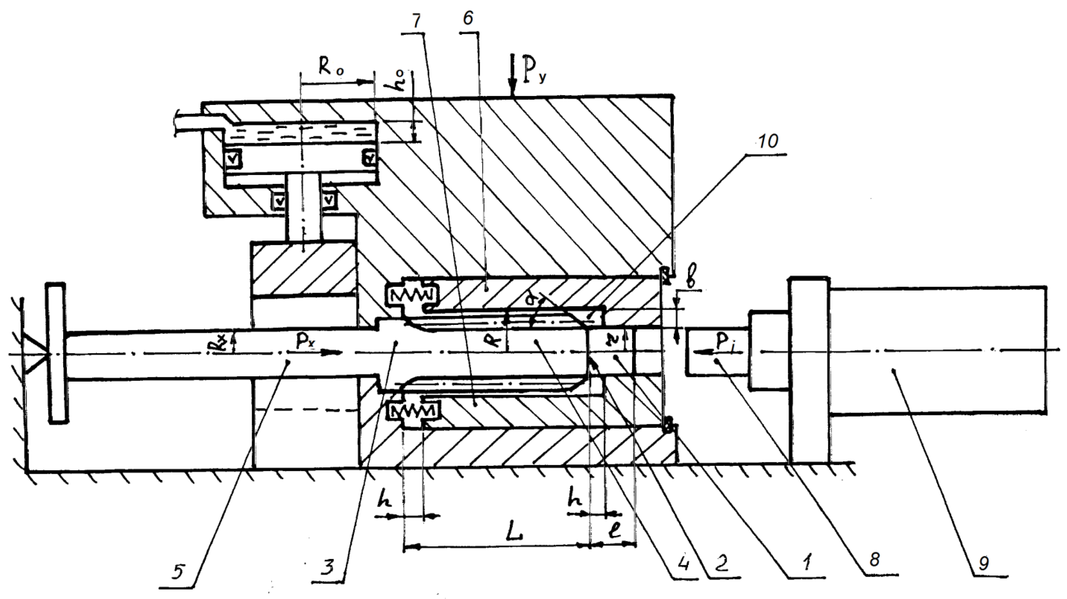
Figure 1 shows a scheme for processing a worn semi-axle by pressure during its restoration.
The essence of the process is as follows.
Additional material, which compensates for wear and creates allowances for cutting, in the form of a compensator (1) with a length of l L, is pre-welded, by butt welding, onto the non-working end face (2) of the semi-axle (3). Then, locally heated in the zone of the spline surface (4), the semi-axle (3) is clamped to the shank (5) with a wedge mechanism. In this case, the difference in the diameters of the untreated shank (5) at the clamping point is compensated for by the stroke of the piston h0, built into the stamp of the hydraulic cylinder with the radius of the piston R0. In the absence of such compensation for deviations in the dimensions of the shank (5), when the half-matrices (6 and 7) of the stamp are closed, the axis of the shank rod (5) may shift relative to the axis of the spline surface (4), which in turn will lead to curvature of the semi-axle (3).
The axial force Px of the shank (5) ensures the immobility of the semi-axle (3) using a one-sided draft with the force Pi of the spline surface (4) and a welded compensator (1), except for in the occurrence of slippage. After clamping the part with a punch (8) fixed to the rod of the power hydraulic cylinder (9), deformation is performed with the force Pi of the spline end (4) by the punch (3), increasing with the resistance of the plasticity of the metal, forcing the compensating metal (1) to be pressed into the body of the semi-axle (3), and moving the base metal to the worn surface (4), filling the engraving (10) formed by the horizontally movable closed half-matrices (6 and 7). In this case, the outer diameter of the spline surface (4) increases to 2R with a one-time filling of hot metal into the spline depressions.
The above power calculations are necessary for the correct choice of forging and pressing equipment, the design of die tooling, and the formation of elements with sufficient, necessary strength indicators.
A special analysis feature of the process of obtaining hot volume by precipitation in a closed die, from long cylindrical forged parts with variable profiles, is the mandatory gradual analysis of metal movements and the gradual determination of the energy-power characteristics of the formation process. For instance, the formation of shanks when restoring the pressure of the rear semi-axles of KamAZ trucks is accompanied by the formation of an undesirable step transition, where the compensator is welded onto the end of the shank, which is the most likely place for the formation of a clamp. One of the tasks of this study was determining the causes of, and eliminating the prerequisites for, the formation of defects in the form of clamps.
The precipitation process of the stepped surface of the semi-axle shank can be conditionally divided into stages: (a) mainly axial flow of metal, with centers of radial displacements (
Figure 2a); (b) filling the gaps in the matrix from the end side of the deformed part (
Figure 2b); (c) the final stage of filling the stamp engraving (
Figure 3a); (d) complete closing of the deforming elements of the stamp (
Figure 3b).
3.2. Step-by-Step Analysis of the Kinematics of Metal Movements
Initially, the metal heated to plastic-deformation temperature can hypothetically move in both radial and axial directions. In this case, the radial movement is insignificant. The metal flow in the first stage is determined by the value of the minimum axial load. The resistance to deformation when the punch touches the end of the heated metal is equal to the yield strength of the metal at a given temperature, and the shear force of the metal is determined by the cross-sectional area of the deposited rod. The required initial deformation force
P0, taking into account the friction force on the matrix walls when pushing metal through it, is determined with the formula:
where
r is the radius of the matrix hole, mm;
σs is the yield strength of steel at 1000 °C, MPa;
μ is the friction coefficient of the heated metal against the matrix walls;
Lκ is the length of the cylindrical section with a small radius, mm; and
h is the width of the cylindrical section of the part located in the stamp engraving, mm.
To determine further possible directions of metal flow, the universal method of sliding lines was used, which consists of constructing the trajectories of the main tangential stresses. In the case of
, the field of sliding lines is shown in
Figure 2a. From the scheme of the field of sliding lines, it can be seen that there are two centers of plastic deformation. The first is at the point of metal yield into the free cylindrical belt of the stamp engraving, and the second is on the surface of the tapered transition of the steps on the semi-axle shank.
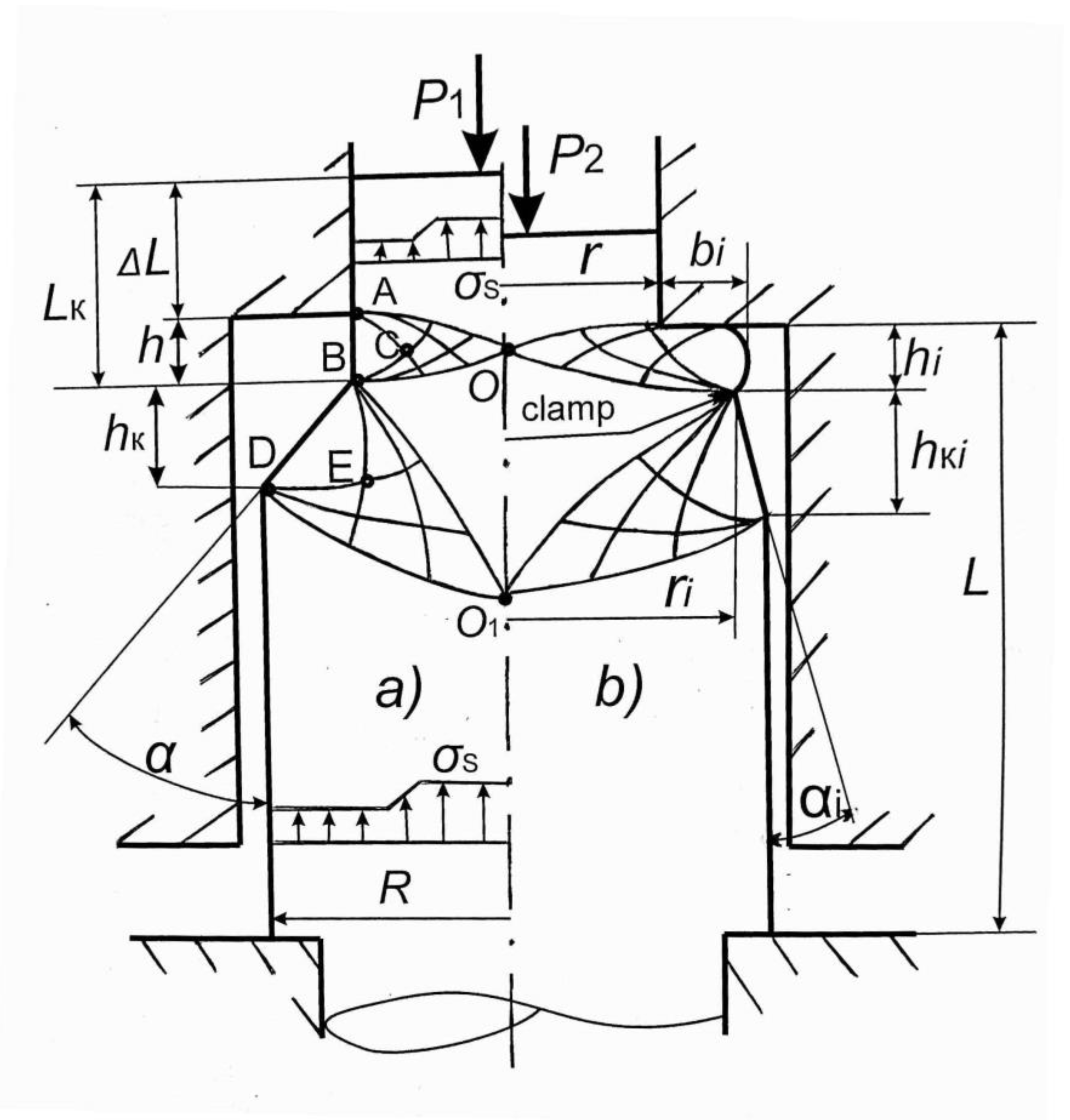
Figure 2.
Stages of the precipitation process of a stepped semi-axle shank with an applied field of slip lines: (a) the first stage—axial flow of metal with centers of radial displacements; (b) the intermediate stage—filling the gaps in the matrix from the side of the end face of the deformed forging.
The first field of sliding lines (AOB) corresponds to the typical sliding field when metal is forced into the flash gutter during hot stamping. The next field of sliding lines (BO1D) corresponds to the typical field of sliding lines in closed stamping, when the corners of the stamp engraving are filled in. Based on the hypothesis of a rigid-plastic body, it can be assumed that plastic deformation in the first stage occurs in the zone outlined by the boundaries of the fields of sliding lines. The rest of the part body is conventionally rigid. The deforming force required to displace the metal into the cylindrical receiver belt, through the rigid zone of the OBO1, acts on the cone junction, forcing the metal of the cone junction
hκ to move in the radial direction.
Figure 2a also shows the plots of the distribution of normal stresses
σs, constructed based on the fields of slip lines. The deformation force
P1 of the cylindrical
Rcyl and conical
Rcon sections, taking into account the field of the sliding lines AOB, can be determined by the formula:
where
R is the radius of the base of the cone, in mm;
α is the angle of inclination of the forming cone, in deg; and
λ is the degree of deformation, determined with the formula:
where
F is the cross-sectional area of the deformable body, in mm
2; and
f is the free surface area of metal flow, in mm
2.
3.3. Analysis of the Stress-Strain State of the Part
The movement of metal in the radial direction is accompanied by the formation of a barrel-shaped annular section [
15], while the probability of the appearance of a clamp increases. To ensure a more uniform flow of metal in the cylinder-cone zone towards the minimum resistance, it is necessary to observe the condition of equal resistance, according to which the resistance to deformation in the cylindrical and conical parts should be the same, i.e.,
Rcil =
Rcon. Then, the optimal angle of the cone chamfer can be determined according to the formula:
The calculations showed that the maximum permissible value of the angle of inclination of the forming cone chamfer, at which it is guaranteed that the appearance of clamps and cold junctions can be avoided, is 37°. According to the working drawing, the chamfer angle of the semi-axles of the KamAZ truck is 30°, which does not exceed the calculated value. If the chamfer angle exceeds 37°, then, before settling in the stamp, it needs to be reduced with cutting to the calculated one.
The further deformation process proceeded unsteadily, therefore, and the analysis of the kinematics of the metal flow was carried out in stages, with the uniform recommended intervals of relative deformation in
ε = 10%. It is necessary to determine the characteristics of the deformed state and the technological forces of deformation for each stage [
4]. It should also be taken into account that the filling of the stream is uneven, and primarily from the side of the punch. It was assumed that the forming cone at the draft retains its rectilinear shape during precipitation; only the angle of inclination changes to 0°. The intermediate position of deformable surfaces with deformation centers in the diametrical receiver of the stamp is schematically presented in
Figure 2b.
As the forming punch moves, the cone transition settles with a change in the shape of the product, increasing the height of the belt
hi while reducing the height of the cone part
hκi and the angle of inclination of the generatrix
αi. From the condition of volume constancy of the original and transferred metal, it follows that:
The radius of the base of the cone part
ri can be determined:
The value of
hκi is calculated based on the assumed value of the relative strain
ε:
The increment in the outer diameter is expressed through
bi:
The analytical expression of the deformation force
P;2 at the second intermediate stage of deformation is calculated below.
In the resulting equation, the presence of
takes into account the friction force of the displaced metal on the end of the matrix. Based on the assumption that
Pcyli = Pconi, the value of the radial movement of the metal
bi can be expressed:
These theoretical calculations showed that, in the presence of a transition chamfer with an angle of 30–37° in the place of the step transition of cylindrical surfaces on the semi-axle shank, the clamping value, when the metal is displaced with the punch into the free space of the die matrix, is not more than 0.5 mm, which does not exceed the allowance for subsequent processing of this section of the forged part with cutting.
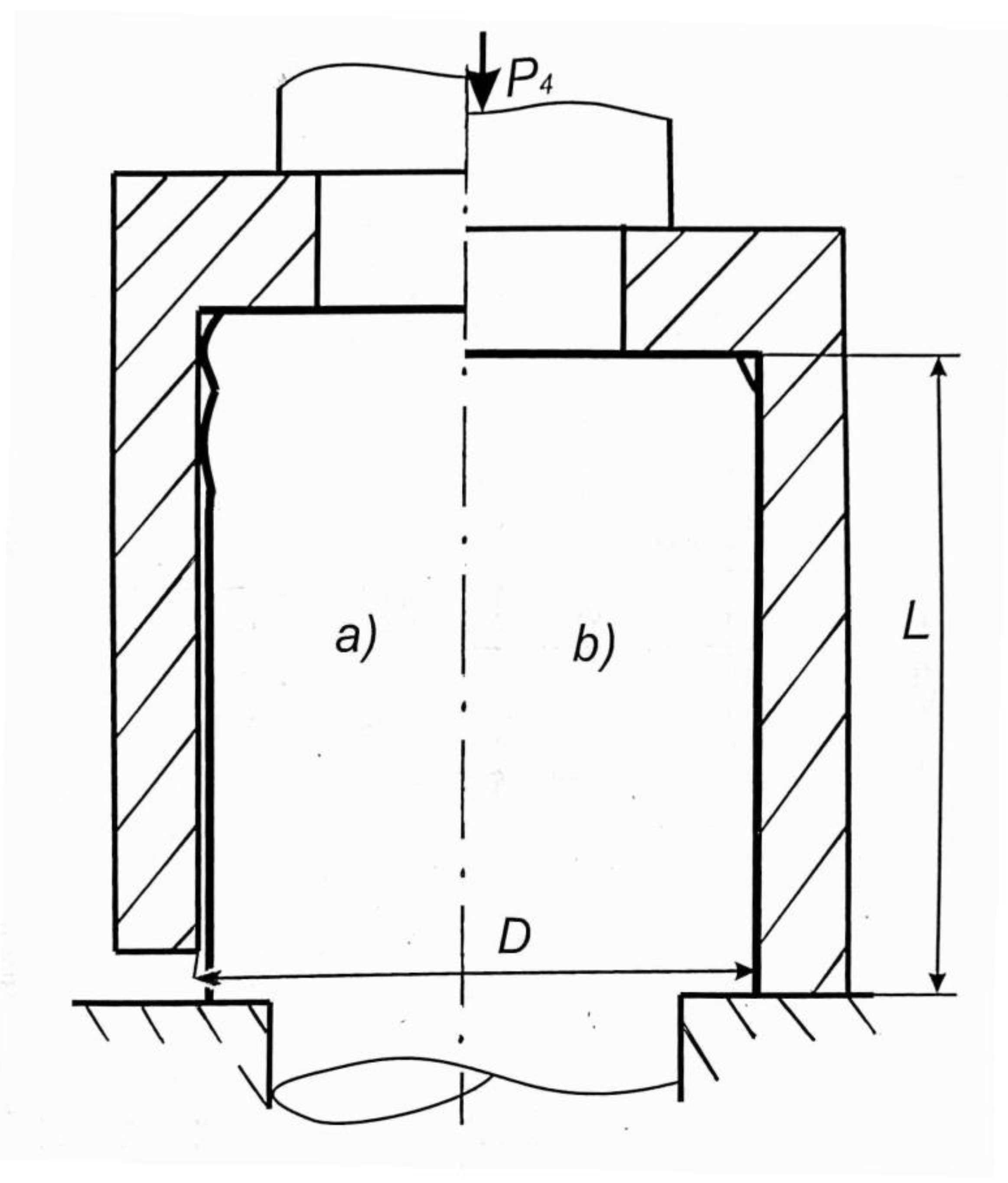
The process of final formation of the semi-axle shank proceeds according to the scheme shown in
Figure 3. The final stage of forging consists of filling the gaps and stagnant zones between the outer diameter of the semi-axle shank and the inner diameter of the matrix with metal [
16].
Figure 3.
The final stages of forming the semi-axle shank: (a) the final stage of filling the stamp engraving; (b) complete closing of the deforming elements of the stamp.
Figure 3.
The final stages of forming the semi-axle shank: (a) the final stage of filling the stamp engraving; (b) complete closing of the deforming elements of the stamp.
As the deformation temperature of the part decreases from 1100 °C to 900 °C, due to cooling down, when calculating the forming force, it is necessary to make an adjustment for the increase in the resistance of the metal to deformation. The yield strength for 47 Mn8 steel at 1100 °C is 31 MPa, 51 MPa at 1000 °C, and 83 MPa at 900 °C. The value of the friction coefficient varies depending on the roughness of the working surfaces of the punch and matrix, within the range of μ = 0.1–0.5. As diffusion adhesion of the metal to the end face of the polished tool is not excluded in the process of deformation, then we take μ = 0.3.
The force at the third stage is determined with two components: the draft of the cross-section, to a diameter of
D = 2
R, accompanied by “barrel formation” on the lateral outer surface of the part, and the movement of the metal into stagnant zones, overcoming the friction force on the surface of the matrix. Forming at this stage occurs when the joint movement of the punch and the “floating” matrix coincides with the direction of the metal flow. The value of force
P3 is determined with the formula:
where
L is the length of the deformed section of the surface, mm;
R is the forged part radius, mm; and
μ is the friction coefficient of the metal against the matrix walls.
Having analytically identified the characteristics of the deformed state at each formation stage, determining the force
P4 is likely dependent on sufficient deformation of the semi-axle draft by the punch, which is crucial in the selection of pressing equipment, the design of die tooling elements, and conducting-strength calculations.
3.4. Determination of the Energy-Power Characteristics of the Process
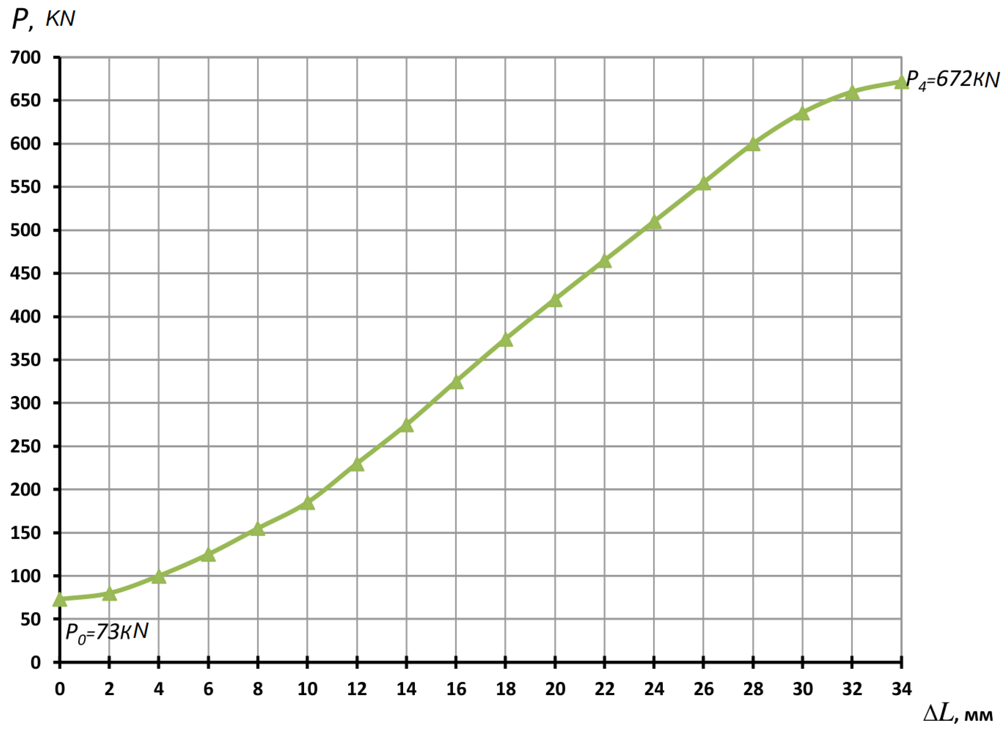
According to our theoretical analysis and the calculations based on it, the forces of deformation stages of the rear semi-axle shanks of KamAZ 5320 trucks were determined. A graph of the dependence of the force on the value of upsetting was constructed (
Figure 4), which is of decisive importance in the development of technological processes for manufacturing and restoration. The method of restoring the semi-axles is described in the source paper.
The theoretical curve in the diagram (
Figure 4) was obtained after substituting numerical values into Formulas (1), (2), (9), (11), and (12).
It is advisable to use the graph as a nomogram when designing die tooling.
3.5. Results of a Multifactorial Experiment
Carrying out a multifactorial experiment when restoring drive semi-axles, by pressure, allowed us to obtain a model that adequately describes the relationship between the force of the deforming punch
P, the precipitation amount
ΔL, the heating temperature of the part
T, and the diameter of the compensator
d =
2r:
It has been experimentally established that the maximum required de-formation force at a pre-deformation heating temperature of T = 1200 °C, and a precipitation value of ΔL = 30 mm, is 650 kN, which is consistent with the data of theoretical studies, with a discrepancy of less than 5%.
The results of torsion tests on the restored semi-axles showed that, at the welded joint of the compensating metal with the splined part, the values of the destructive torque were within Mraz = 23,300–23,700 N·m, which significantly exceeds the technical requirements of the working drawing.
The results of measurements of the concentration of micro-stresses arising in the area of fusion of the compensator with the end of the semi-axle, carried out by decoding interference lines on diffractograms, showed a result of 176.6 MPa, which is less than 10% of the tensile strength of alloy steel 47 Mn8, of which the semi-axles are made. This confirms the absence of a negative impact of additional micro-stresses on the performance and durability of the parts restored by the proposed method.
It was established that, during high-temperature deformation, the worn-out defect layer is displaced into the allowance zone and removed by cutting, and subsequent chemical-thermal treatment contributes to the restoration of the initial structure, as well as the physical and mechanical properties of the working surfaces.
Grinding of grains up to 2.3 points, their reorientation, and the reduction of dispersion occurs under a pressure of about 400 MPa along the shear planes, which contributes to surface hardening and the reduction of segregation.
Metallographic studies have established that the structure of the hardened layer is fine-needle martensite, with troostite inclusions in the transition zone, which meets the technical requirements of the manufacturer.
All this confirms the absence of a negative impact of additional micro-stresses on the performance and durability of the parts restored by the proposed method.
4. Discussion
Based on the restoration of 2.5 thousand semi-axles per year, using a representative part mass of 20.6 kg, the total saving of 47Mn8 structural alloy steel was determined, which amounted to 50 tons.
The average annual economic effect of the introduction of technology for the restoration of semi-axles by plastic deformation, considering the price of a new factory part to be 9250 rubles, the cost of its restoration to be 7400 rubles, capital expenditures of 900 thousand rubles, a discount coefficient of 0.15, and an annual program for the restoration of 2500 parts, would amount to 4.49 million rubles, which after conversion at the exchange rate, amounts to 54,490 euros. The payback period of investments would be 6 years.
The restoration of worn-out long-spline semi-axles with a cylindrical shank includes butt welding a cylindrical compensator, the length of which is selected based on the volume of worn metal and allowances for subsequent cutting, to the non-working end face, after which the workpiece is locally heated in the area of the worn spline surface to the metal ductility temperature, and its one-sided sediment is placed in a die with a detachable matrix punch, with a force specified in the direction of reduction, which makes it possible to achieve some reduction in the load on the deforming tool, while increasing the durability of the die tooling.
The application of the proposed technical solution will make it possible to form an additional production option for the recycling of worn-out steel machine parts in the territory of the Russian Federation.
5. Conclusions
A fundamentally new direction in the creation of technologies for the restoration of extremely worn parts by plastic deformation, with preliminary application to non-working surfaces by contact butt welding or surfacing of a wear-compensating metal, is characterized by high efficiency. Metal saving is achieved by using fragments of similar worn-out parts as compensators. The properties of the restored sections and surfaces are identical to the serial parts, and the regulated reliability is comparable to the durability of a new product.
The implementation of the technological process of restoring worn semi-axles in repair production, using the results of the power calculations of pressing equipment and die tooling provided in this article, confirmed the possibility of obtaining high-quality forged parts, with uniform and sufficient allowances for further cutting, by plastic deformation from worn parts.
The refined step-by-step calculation of the force characteristics of the deformation process revealed reserves for reducing the deformation force, which made it possible to reduce the load on the tool, and thereby increase the durability of the used pressing equipment and die tooling. The calculated maximum force of deformation by the draft was 672 kN, with a clamping force of 900 kN, and an effort ensuring the locking of the die at 2400 kN, which is a guideline when choosing forging and pressing equipment.


