Abstract
Circular tubes are widely used in daily life and manufacture under bending load. The structural parameters of a circular tube, such as its wall thickness, number and shapes of ribs, and supporting flanges, are closely related to the tube’s bending rigidity. In this study, a tube with eight ribs and a flange was optimized, in order to obtain the lowest weight, through comprehensive structural optimization. We obtained the optimal structural parameters of the tube and the influence of the structural parameters on the tube’s weight. The structural parameters of tubes with different numbers of ribs were optimized. The tube with different number of ribs had the same inner diameter, bending load, and length as the tube with eight ribs. We conducted an experiment to verify the structural optimization simulation. Different tube sizes were subsequently optimized. The optimized tube with four trapezoidal ribs and a flange reduced the weight by more than 73% while maintaining the same deformation. The weight of the optimized tube with a flange reached a stable value after four trapezoidal ribs were added. When the number of ribs was two, the weight was the largest. The analysis results were consistent with the numerical results. A new AWATR (appropriate width and thickness of ribs can improve the bending rigidity of the tubes) formula was proposed, which can effectively improve the bending rigidity of tubes. Different shapes of tubes were optimized and compared. The optimized tube with four trapezoidal ribs and a flange was the lightest and easy to manufacture.
1. Introduction
Circular tubes are widely used as components in various applications, including buckets, columns for buildings, shafts, poles, and oil storage tanks. Many researchers have studied circular tubes, in an attempt to increase their strengths and lowering the associated waste by improving the structures of tubes [1,2,3,4,5,6,7]. These structures comprised sandwiched sinusoidal lateral corrugated tubes and circular braided composite tubes, among others. Studies on the structure of circular tubes have been carried out, in order to increase their strength. Hui et al. studied the behaviors of circular concrete filled double steel tubular slender columns and beams. They established a finite element model, in which the parameters were hollow ratio, eccentric ratio, and material strength. The model predicted load-bearing capacities and load–deflection developments of slender columns and beams, under the efficient structure [8]. Jin et al. built a finite element model to analyze the mechanical properties of tubes under combined axial compression and bending loads. They studied the effects of the diameter by thickness ratio and eccentricity by diameter ratio on the structure’s strength and buckling strain [9]. Baroutaji et al. designed a new circular tube with perimetrical thickness gradient under lateral loading. The circular tubes were optimized and the optimal thickness gradient parameters were determined, satisfying the condition of best crashworthiness [10]. Xiao et al. introduced novel sandwiched sinusoidal lateral corrugated tubes. The energy absorption was increased up to 35.6%, compared to the sum of the values of the constituent tubes under axial compression [11]. Rotich et al. studied the improved mechanical properties of four-step three-dimensional (3D) circular braided composite tubes under axial compression loading. They found that the unit cells in the inner and outer parts were stiffer than those in the middle part. These results may aid in the design of optimized 3D circular braided composite tube structures [12]. Wen et al. studied the effect of the size of circular concrete-filled steel tubes with different diameters and tube-diameter-to-steel thickness ratios on the bearing capacity. Under different ratios, a size-related model was established, which can estimate the bearing capacity of large-sized circular concrete-filled steel tubes [13]. Jordana et al. employed various numerical techniques to obtain the non-linear static equilibrium path of a cylindrical panel using structural stability analysis. They concluded that the value of the critical load was strongly dependent on the sign of the amplitude of the geometrical imperfection [14]. Ngoc et al. proposed a new tubular corrugated configuration mimicking a coconut tree profile, which showed potential for the design of an efficient energy absorber [15]. The above research mainly focused on the analysis of structural vibration and anti-damage when the direction of force was certain and the number of variable parameters was at most three, such as the diameter, thickness, and eccentricity ratio of the tube [16,17,18]. On the basis of the existing research, in this work, we increased the number of variable parameters of the tube to nine and set the force direction to be arbitrary. If there are too many structural parameters, the constraints and conditions need to be increased while, at same time, there will be no definite formula. In the case of there being too many variable parameters (such as the nine variable parameters, including the wall thickness, flange diameter, flange thickness, rib shapes, and number of ribs), there are no definite formulas, which leads to a higher calculation time, calculation difficulty, and increases risk. In the case of the bending force direction changing, we need to fully consider the forces of different conditions, in order to meet the deformation of the structure. The study of tubes with uncertain bending force direction and more variable parameters poses a great challenge. However, circular tubes with uncertain bending force direction and many variable parameters can be seen everywhere, in both manufacture and daily life.
Many forces are applied to circular tubes with unknown bending directions, such as rotating beams, street lamps, and beams on buildings. When designing a complicated circular tube, there exist no accurate methods for obtaining the multiple design parameters, such as the wall thickness, flange diameter, flange thickness, rib shapes, and number of ribs. These parameters are directly related to the deformation of the circular tube and other properties. Thus, they are quite important. In production, engineers design complicated circular tubes based on actual production requirements and previous experience.
With scientific and technological development, structural precision demands are growing to fully guarantee the strength of structures. Under the increasingly rigorous environmental protection regulations and the depletion of energy sources, applying lighter tubes has been confirmed to be efficient energy reduction and environmental protection measures in automobile, transportation, aerospace, and civil engineering applications. For example, aerospace instruments, medical equipment, electronic equipment, machine tools, and optical instruments have high precision requirements for key components, where circular tubes with high precision requirements and low weight under bending moments are commonly used [19,20,21,22,23,24,25].
Based on the above unresolved practical requirements (such as multivariable parameters, uncertain direction of force, and lightweight optimization tube structure), problems (e.g., there is no formula for structural layout design, engineers do not know which structural layout is optimal, those structural layouts may waste materials, and there is no basis for regular structural layout), and requirements for the sustainable development of circular tube design, in this study, multiple parameters of circular tubes with eight or other numbers of ribs under unknown bending moment directions were optimized using the proposed flowchart. This flowchart showed how to use CAD (computer-aided design) and CAE (computer-aided engineering) to optimize a structure. Through the optimized results of the structure, we found that, when the number of ribs was smaller than four, the weight of the optimized tube was heavier. When the number of ribs was higher than four, the weight of the optimized tube reached stable values. Thus, an innovative tube with four trapezoidal ribs and a flange was proposed under unknown bending moment directions. The weight of the optimized tube with four trapezoidal ribs and a flange was 15.8–73.2% lighter than existing optimized tubes, while maintaining the same deformation. A new formula for AWATR was established, in order to improve the tube bending rigidity through analysis of the optimized tube with one and two ribs.
2. Methodology
2.1. Principle of Finite Element Analysis in ANSYS Software
For a tube, the increase of any element that constitutes tube’s geometry can cause tube’s volume to increase. The elements that constitute tube’s geometry can be expressed by , , , and . The tube weight can be expressed as follows:
Thus, if , , and increase, the mass of the tube increases. M is the weight, is density, g is the gravitational acceleration, is the increment of volume, is the increment of length in the x direction, is the increment of length in the y direction, and is the increment of length in the z direction (as shown in Figure 1). As the thickness of tube increases near the fixed end, the amount of bending decreases and the weight increases. However, if the thickness is too large, the deformation is larger due to the material properties and the greater weight. Far from the fixed position, the thinner the tube is, the smaller the bending deformation is and the lighter the tube is. However, if the thickness of the tube far from the fixed position is too thin, the deformation would be larger due to the material properties and lighter weight. Therefore, it is urgent to combine the structural parameters reasonably to find the lightest structure under certain deformation.
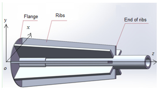
Figure 1.
Three-dimensional preliminary structure of the tube.
Some simple structures may have formulas, while complex structures generally do not. For example, the complex tube deformation was a function of nine independent variables: Number of ribs), as summarized in Table 1. There was no equation that related the dependent variable to these nine independent variables. For simple structures, the existing bending deformation formula can be used. For complex structures, the deformation of circular tube can be determined by changing the nine independent variables and loads using the finite element method.

Table 1.
Assigned variable parameters.
The complex structures were divided into many finite 3D elements (as shown in Figure 2) using finite-element analysis software (ANSYS). A mesh containing tetrahedral elements was generated to represent the tube, as shown in Figure 2. The stiffness matrix for each element of the tube is given as follows:
represents the loads of all k nodes on a element, where are nodal loads in the x, y, and z directions of this element at node i (). is defined as follows:
where is the ith nodal force of the element caused by unit deformation of the jth degree of freedom of the element. is related to E (elastic modulus of the material) and (Poisson ratio). The displacements generated at k nodes are as follows:
where , and , , and are the displacement of the node i in the x, y, and z directions, respectively, as shown in Figure 3.
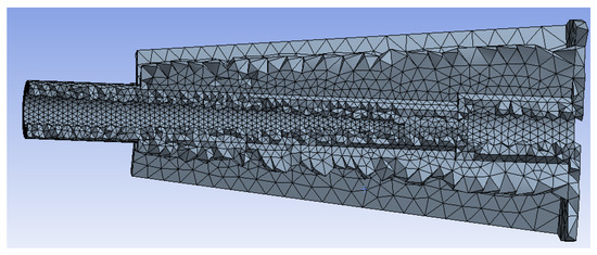
Figure 2.
Meshed overall structure.
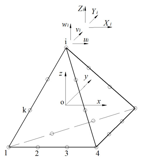
Figure 3.
Tetrahedral element.
Each element contains nodes, and adjacent elements have several common nodes. The equilibrium equation of the tube is constructed based on these equilibrium conditions. The equations of these elements that are generated around each node at these junctions:
where are the nodal loads on the overall structure. The loads on the tube are due to its own weight and an external load (e.g., forces in different directions). The whole structure has n nodes. are the nodal displacements of the overall structure. The displacements of the nodes represent the deformation of the tube. According to the correspondence between each stiffness coefficient of a element and each stiffness coefficient of the overall structure, the stiffness coefficients of all the elements are superimposed to form the corresponding overall stiffness coefficient, and the overall stiffness coefficient matrix is obtained as follows:
where is the rth nodal force caused by the unit deformation of the sth degree of freedom of the entire structure [26,27].
2.2. Optimization Analysis
The basic principle of the design optimization was to obtain the extreme value of the objective function and the optimal design scheme using various optimization methods, constructing the optimization model, and performing an iterative calculation based on the requirements of the design.
The mathematical model of the optimization problem can be expressed as follows:
where is the objective function of the design variable, X is the design variable, and G(X) is the state variable [28]. For the following tube, tL1, wide, tflange, tL2, tL1L2, larib, lerib, trib, and the number of ribs were the design variables , for which upper and lower limits were specified, as shown in Table 1. The deformation of the tube was the state variable , which had an upper limit of 0.01 mm. The weight of the tube was the objective function , which was to be minimized.
The optimization result was obtained by changing the values of the design variables using various optimization methods. There are many optimization methods, such as screening, MOGA (multi-objective genetic algorithm), and NLPQL (non-linear programming by quadratic Lagrangian). MOGA is an improvement based on the non-dominated sorting genetic algorithm II. It supports multiple goals and constraints. It requires an input of continuous parameters and provides greater accuracy than the screening and NLPQL methods, which is ideal for calculating global maximum/minimum values while avoiding local optimal traps. Thus, MOGA was used in this study. The MOGA procedure is as follows. First, a population of a group of individuals is generated. Each individual represents a potential solution to the problem. Second, each individual’s fitness is evaluated, and individuals with high fitness values are selected. Third, the individuals chosen are crossed and mutated, producing new groups. The second and third steps are repeated. After several generations, certain convergence conditions are satisfied, and the optimal or approximate optimal solution is obtained [29,30]. The minimum value of the weight of the tube was achieved using MOGA with finite element analysis software.
2.3. Modeling and Optimization Based on CAD and CAE
CAD was used to model the tube structure in three dimensions and set the parameter values. The parameterized 3D model built using CAD software was imported into finite element analysis software [31]. In ANSYS, the extreme value of the deformation was set, and ranges of the structural parameters were selected. The design variables were structural parameters. In ANSYS, the MOGA optimization method was selected to design a tube such that its weight was minimized and the deformation met specific requirements [32,33]. Finally, the structure was optimized by finite element analysis. The specific process is shown in Figure 4.
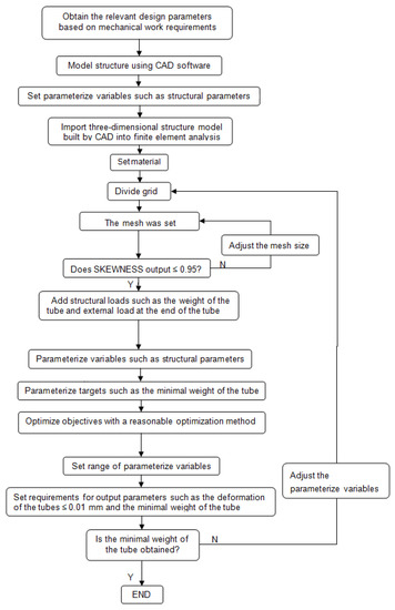
Figure 4.
Flowchart for structure optimization.
For mechanical structures under a constant external force and with specified deformation constraints, this specific process can be used to achieve the lightest-weight optimization target. The ranges of mechanical structural variables were set, and the optimal combinations of these mechanical structural variables were obtained by simulation analysis and optimization. This process can be used for the other constraints and the mechanical structural variables as well.
2.4. Model of Tube with Eight Ribs
Circular tubes with ribs arranged around the outside are universal in production, such as mirror tubes [34,35] and beams. At the beginning of modeling a tube structure, the number of ribs which is most suitable is unknown. Too many ribs will increase the calculation time of ANSYS, the processing time, and the difficulty of processing the tube. According to general production practice, the number of ribs ranges from 0 to 20. In this range, a tube with eight ribs was selected, in order to optimize its structure, in this study. The length of the tube and the size of its inner circumference were fixed based on the requirements of the parts that are usually held by the tube. The structural parameters that could be changed are as follows: the wall thickness of the tube, the thickness of the flange, the diameter of the outer circle of the flange, the length of the other end of the rib, the length of the rib in the axial direction of the tube, the thickness of the rib, and the number of ribs around the tube.
A tube is used to support the two different circular parts. For simple processing and assembly and to reduce the cost, tubes are typically circular. There is a flange at the front of the tube and ribs around the outside of the tube. The flange is used to fix the tube to another support flange.
In this study, the number of ribs was set to eight. These ribs were evenly distributed in the circumference direction of the tube and were used to improve the tube’s bending rigidity. Since many tubes are used in spaceflight, aviation, and green production, it is increasingly important that the parts required are as light as possible. Many tubes in precision equipment require high operating accuracies. Thus, tubes must be as light as possible, and, in this study, the deformation of the tubes was required to be controlled to mm.
2.4.1. Definition of Fixed and Variable Parameters
The overall structure of the tube was obtained based on the sizes of the circular parts held in the tube and its part length or working path, as shown in Figure 5. The inner diameters of the tube were D1 = 30 mm and D2 = 20 mm. The tube lengths were L1 = 62.9 mm and L2 = 243.4 mm. The tube was constructed from aluminum alloy 6061. The properties of the material were follows: density kg/mm, Young’s modulus MPa, Poisson’s ratio = 0.332, yield strength = 55 MPa, tensile ultimate strength = 310 MPa, and shear modulus = 25,601 MPa. These were fixed values, and the remaining structural parameters were variable.
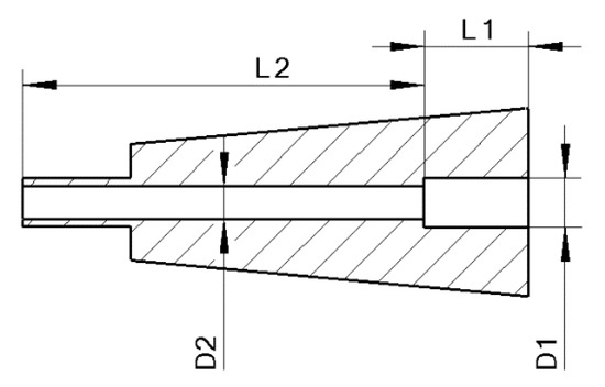
Figure 5.
Constant structural parameters of the tube.
The modeling was performed using CAD software (e.g., SolidWorks), and the parametric design of the tube was carried out. The thicknesses of the two walls of the tubes and the step connected thereto were regarded as three parameters. The thickness of the flange at the front of the tube was the fourth parameter. The outer diameter of the flange was the fifth parameter. The front of the rib was connected to the outermost contour of the flange. The length of the end of the rib, the length of the rib in the axial direction of the tube, the thickness of the rib, and the number of ribs were the sixth, seventh, eighth, and ninth parameters, respectively. The preliminary structure of the tube is shown in Figure 1. The variable parameters of the tube were assigned, as shown in Table 1 and Figure 6.
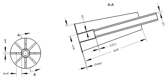
Figure 6.
Variable parameters of the tube.
2.4.2. Work and Constraint Setting and Parameterization
After defining the parameters, the 3D model built in SolidWorks was imported into the finite element analysis software. The tube material was set, and the mesh was generated based on the quality requirements of the analysis. When the analysis results no longer changed with the size of the mesh, the mesh was no longer refined. The mesh quality was checked using the SKEWNESS function in ANSYS, with values between 0 and 1. SKEWNESS outputs 0 for the best mesh quality and 1 for the worst, and a mesh quality of 0.95–1 is unacceptable. The result of this meshing structure is shown in Figure 7. It met the mesh quality requirements for the computational analysis. The bottom surface of the flange was fixed. In an actual design, the working load of the structure under the worst conditions is taken as a fixed value for the design variables of the structure. If this worst working condition is met, loads under other conditions will also meet requirements of the structure. Based on the working force, the tube was subjected to its own weight (the force was applied in the direction). In the worst condition, the end of the tube was subjected to an external load of 23 N (in the direction), as shown in Figure 8. The operating acceleration of the tube as well as the buckling and torsion on the structure were neglected in this study. In other working conditions, if the buckling and torsion effects are large, these loads can be added to the structure and subsequently analyzed and optimized using the flowchart of the structure optimization procedure shown in Figure 4. Appropriate size ranges for the arguments based on the process and actual conditions were set to the values shown in Table 1.
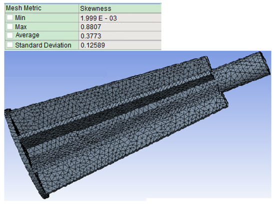
Figure 7.
Meshed tube.
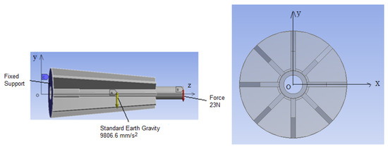
Figure 8.
The tube is constrained and loaded.
These conditions and constraints were set, and the deformation analysis was performed [36,37,38]. Next, the input variables, weight, and deformation were parameterized. A two-dimensional curve of the variation of each input parameter with the output parameter was plotted. Finally, the optimal combination and influence of various parameters on the weight and deformation were obtained by optimization using the finite element analysis software.
3. Optimal Results and Analysis for Tube with Eight Ribs
3.1. Tube Deformation and Weight Change with Input Parameters and Avoidance of Worst Input Parameters
Through finite element analysis, the relationship between the deformation of the tube and the input parameters was obtained. For parameter tL1, within the range of 1–6 mm, the variation of the deformation of the tube with the input parameters is shown in Figure 9. At tL1 = 0.5 mm, the deformation had a maximum value of 0.5 mm. At tL1 = 3 mm, the deformation was about 0.25 mm, and the deformation was also large. Other parameters changed the deformation by mm. There was no evident variation trend, but the maximum deformation should be avoided. For parameters wide, tflange, tL2, tL1L2, trib, larib, and lerib, the variation behaviors of the deformation of the tube with the input parameters were similar to that of tL1. When wide = 15 mm, tflange = 1 mm, tL2 = 1 mm, tL1L2 = 1 mm, larib = 100 mm, lerib = 0, and trib = 1 mm, the deformation had a maximum value of 0.5 mm. There were no evident variation trends, but maximum deformation should be avoided.
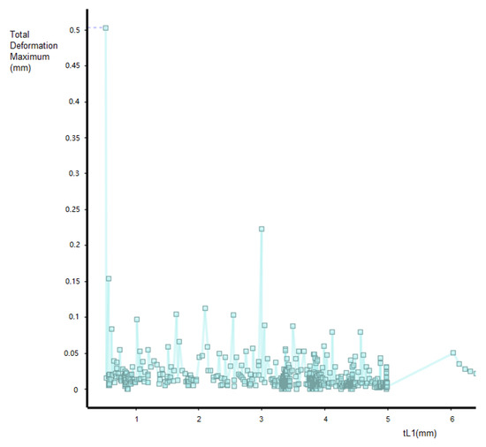
Figure 9.
Variation of tube deformation with parameter tL1.
Based on the above analysis, there was no evident relationship between the input parameters and deformation of the tube. However, tL1 = 0.5 mm, wide = 15 mm, tflange = 1 mm, tL2 = 1 mm, tL1L2 = 1 mm, larib = 100 mm, lerib = 0, and trib = 1 mm should be avoided because the deformation had a maximum value of 0.5 mm [39]. Large values of larib and lerib were desirable because the deformation was smaller.
3.2. Optimized Combination and Influence of Structural Parameters
For a deformation of mm and the lightest weight constraint [40,41], a decrease in the input parameters will reduce the weight. The amount of deformation may increase or decrease, but this is not known in advance. Based on the variation ranges of the input parameters and the constraint requirements, the [42] finite element analysis and optimization method can be used to obtain the optimal combination in this range.
These parameters and the structure were optimized by a multi-objective genetic algorithm. Based on the working performance requirement of the part held in the tube path, the parameter ranges of the independent variables were set, and the constraint parameter deformation was set to a total deformation maximum of mm. For deformations of mm or less, the working accuracy of the parts can be ensured. To conserve material and reduce resource waste, the target parameter tube weight was set to be minimized. The structure was subsequently optimized, and these optimization results for eight ribs are shown in Table 2.
Table 2.
Optimization results for eight ribs.
A set of parameters optimized by the multi-objective genetic algorithm is shown. Under the minimum weight constraint and the requirement that the deformation was mm, the parameter combinations were as follows: tL1 = 3.08 mm, wide = 41.71 mm, tflange = 3.13 mm, tL2 = 2.05 mm, tL1L2 = 3.18 mm, larib = 295.08 mm, lerib = 32.98 mm, and trib = 1.69 mm. Furthermore, the geometry mass = 0.643 kg and total deformation maximum = 0.00978 mm.
As shown in Figure 10, the parameters that had a significant impact on the weight were as follows: tL1, tL2, and trib. The less influential parameters were tflange and tL1L2. The effects of the input parameters on the weight and deformation followed similar trends.
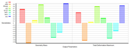
Figure 10.
Effect of input parameters on target parameters.
The above analysis yielded the optimal choice of the wall thickness and flange parameters. The optimal choices of tflange (flange thickness), tL1 (the wall thickness of the tube at L1), and tL1L2 (the step thickness at the junction of the L1 and L2 tubes) were close to 3 mm. The optimal value of tL2 (the wall thickness of the tube at the distal end L2) had a smaller value of 2 mm. The optimal value of wide (the difference between the outer radius of the flange and the outer radius of the tube) had a substantially larger value of 42 mm. The optimal values of the structural parameters of the ribs were obtained as follows. larib (the axial length of the rib) was 295.08 mm. The value of 295.08 mm was approximately 2% less than 301 mm (which was the value of L1 + L2). lerib (the length of end of the rib) was 32.98 mm, and this value was close to the optimal value of wide. trib (the thickness of the rib) was 1.69 mm, which was the minimum.
Evidently, the optimal dimensions of the tube cannot be selected based on intuition. Some of the features of the optimal structure of the tube with eight ribs could be used to evaluate whether other circular tube structures are reasonable overall.
4. Parameter Optimization under Different Rib Numbers
4.1. Parameter Optimization and Discussion
In the previous section, optimal parameters were obtained for a tube with eight ribs. However, the number of ribs on the tube can also be varied. To address this possibility, the number of ribs was varied from 0 to 20, and the other parameters were adjusted based on the number of ribs. The unchanged parameters were the same as those of the tube with eight ribs.
In the absence of ribs, the deformation of the tube was same when the tube with the same structural parameters was subjected to the same bending moment at the fixed point on its axis in any direction. For the case of one rib, the deformation of the tube with the same structural parameters was minimal when the direction of the bending moment and the weight were in the direction of lerib (parallel to the largest surface of the rib), and it was subjected to the same bending moment at a fixed point on the axis, as shown in Figure 11 and Figure 12. However, in actual use, due to the rotation of the tube or changes in the applied force, the force direction is sometimes in the direction of lerib, whereas other times it is in the direction of the trib. To ensure that the deformation of the tube meets the requirements during operation, it is necessary to analyze and calculate the worst working force (the force acts in the trib direction). In other force directions, the tube’s deformation will meet the requirements if the deformation of the tube is mm under the worst working force. First, the tube had one rib when the force was applied in the direction of trib, as shown in Figure 13. The optimized parameters of the tube were obtained. Based on the analysis for one rib, the number of ribs was subsequently incremented. These ribs were evenly distributed in the circumferential direction of the tube. The tubes were analyzed, and the optimization parameters of the tubes were obtained for different ribs bearing the same force.
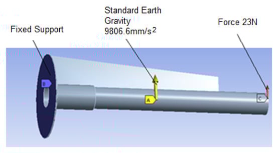
Figure 11.
Directions of forces in the lerib direction.
Figure 12.
Deformation of tube.
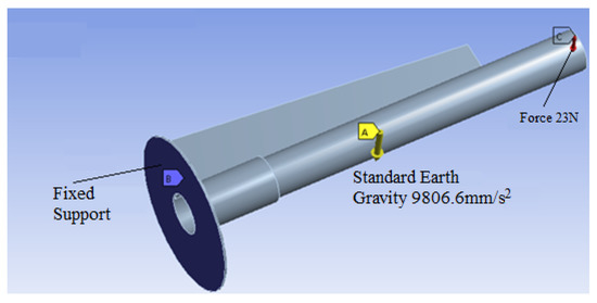
Figure 13.
Direction of force in the trib direction.
Finally, the optimal results for the combination of input parameters with different numbers of ribs are shown in Table 3. The optimal difference between the outer radii of the flange and the tube was 15.1–43.2 mm. The axial length of the rib was 2–48.8% lower than the maximum value (L1 + L2). The length of the end side of the rib was not 0 mm; rather, it was 2.4–45.5% shorter than the front of the rib. When the number of ribs varied within the range of 0–20 for the same inner diameter and length, the weights with 3–20 ribs were smaller when the deformation of the tube was less than 0.01 mm, and the weight with two ribs was the largest. Beyond four ribs, the weight reached a stable value, as shown in Figure 14. The weight with four ribs could be reduced by up to 52.8% compared to the weight of the tube without ribs and up to 59.5% compared to the weight of the tube with two ribs.
Table 3.
Optimal combination of parameters for different numbers of ribs.
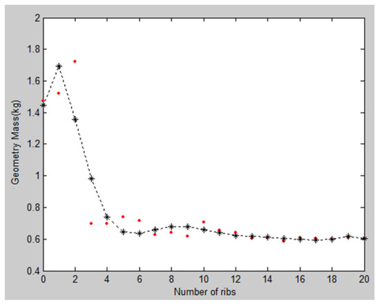
Figure 14.
Effect of number of ribs on weight. The red points represent the weight with different numbers of ribs obtained from the simulation. The * points represent the weight with different numbers of ribs on the lines.
The structural performance without ribs or with two ribs was particularly poor. However, using too many ribs would be inconvenient and increase the cost. Therefore, it is necessary to select an appropriate number of ribs based on the optimization.
4.2. Experiment
The simulation results were validated with a test piece. The test piece weighed 1.727 kg, which was approximately equal to the two-rib-optimized tube weight of 1.721 kg, as shown in Table 3. The test piece had the same dimensions and was composed of the same material as the two-rib-optimized tube, as shown in Table 3.
A test was conducted in which the tube was fixed on a large, stable working platform, as shown in Figure 15. A micron gauge was placed at the end of the tube, and a force of 23 N was applied perpendicular to the direction of the rotation axis of the tube using a force gauge opposite to the micron gauge. After the measurement, the end deformation of the tube was 0.0082 mm.
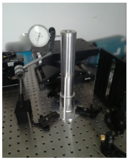
Figure 15.
Method of fixing the tube.
The measured values of the test method were about the same as the simulation result, as shown in Figure 16, which satisfied the requirements. The simulation results were reliable for this case.
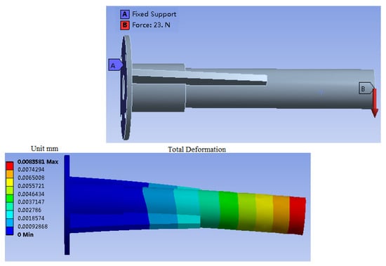
Figure 16.
Simulation of the tube.
5. Structural Optimization of Different Diameter Tubes and Different Ribs
5.1. Optimized Structure of Different Tube Diameters and Optimal Number of Ribs
Under the same maximum deformation of 0.01 mm and axial lengths of the tubes, the positions and directions of the forces for tubes with different diameters were the same as those in Figure 8, and the symbols for the various structural parameters were the same as those in Table 1. The tubes were composed of the same material as the two-rib-optimized tube, as shown in Table 3. The magnitude of the force was varied, and the thickness range of the tubes was required to be 0.5–30 mm to be suitable for actual production. Using the flowchart of the structure optimization procedure shown in Figure 4, 63 sets of optimized structures with different sizes of the circular tubes and different numbers of ribs were obtained. These sets are shown in Table 4.
Table 4.
Optimal combination of parameters for different sizes of circular tubes.
Based on the optimized results in Table 3 and Table 4, the optimal differences between the outer radii of the flange and the tube were 26.9–195% of the outer radii of the tubes. The difference between the length of the end side of the rib and the front of the rib were 0.7–76.7% of the front of the rib. The axial length of the rib was 51.2–98.7% of the maximum value (L1 + L2). The optimal shape of the rib was trapezoidal.
As shown in Figure 17, the weights of the tubes reached stable values after four ribs were added. When the number of ribs was two, the weight was the largest.
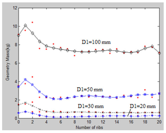
Figure 17.
Effect of number of ribs on the weight. The red points represent the weights with different numbers of ribs obtained by the simulation. The other symbols represent the weights with different number of ribs on the lines.
5.2. Analysis and Judgment Method of Optimal Number of Ribs
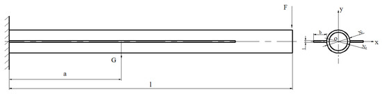
Figure 18.
Side of the rib is parallel to the x-axis.
The parameters F, E, l, , and were specified. F is the load, E is the Young’s modulus, l is the total length of the tube, a is the distance from the tube’s center of gravity to the fixed end, I is the moment of inertia, is the outer diameter of the tube, and is the inner diameter of the tube. A reasonable arrangement of the tube cross section at any x position can ensure that the weight is minimized under the minimum cross-sectional area while keeping I the same to achieve the same maximum deformation requirements. To increase the bending rigidity of the tube, ribs were added around the tube. There are two extreme conditions for the arrangement of the ribs: (a) the side of the rib must be parallel to the x-axis, as shown in Figure 18; and (b) the side of the rib must be parallel to the y-axis, as shown in Figure 19.
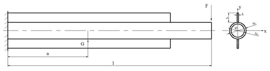
Figure 19.
Side of the rib was parallel to the y-axis.
(a) First extreme rib arrangement:
In this arrangement, the side of the rib is parallel to the x-axis and vertical to the direction of the load, as shown in Figure 18. is the moment of inertia about the x-axis of the annular cross-section of the tube and is the moment of inertia about the x-axis of the rectangular cross-section of the rib. These are defined as follows:
and . b is the length of the side of the rib and t is the thickness of the rib in the cross-section of the tube, which is vertical to the direction of tube’s axle, as shown in Figure 18. is the area of the annular cross-section and is the area of the rectangular cross-section. In production, t is small relative to and , so . The rigidity of a tube with a rib in this direction is reduced compared to that of a tube without ribs, and the same maximum deformation can be achieved only by increasing the weight of the tube with one rib, as shown in Table 3 and Table 4.
In the case of = , the judgment condition of can be obtained:
where , and is closer to . In the case of , the formula for determining how adding ribs in this direction can improve the rigidity of the tube is derived as follows. With , it can be determined that , and, thus,
With and , the following can be obtained:
and, thus,
Finally, to increase the rigidity of the tube compared to the case without ribs, the parameters of the rib should satisfy below conditions:
Formula (14) is referred to as the AWATR (appropriate width and thickness of ribs can improve the bending rigidity of the tubes). Since is unchanged, = . Thus, if t increases significantly, b will decrease significantly.
Using the AWATR, CAD, CAE, and the method in the flowchart in Figure 4, different optimized structures with the side of the rib parallel to the x-axis were obtained, as shown in Table 5. In these cases, trib = t and lerib = b, as shown in Table 5, and the parameters had the same meaning as the corresponding parameters in Table 4.
Table 5.
Optimized structures with the side of the rib parallel to the x axis.
Under the same deformation and material, the different specifications of the tubes in Table 5 resulted in lighter tubes than the corresponding tubes without ribs in Table 3 and Table 4. The results in Table 5 obtained by CAD and CAE simulations were consistent with the above analysis, i.e., adding an optimized rib with the side of the rib parallel to the x-axis of the tube can increase its rigidity compared to the tube without ribs, which can be predicted with the AWATR.
(b) Second extreme rib arrangement:
In this arrangement, the side of the rib is parallel to the y-axis and the direction of load, as shown in Figure 19. The moments of inertia are defined as follows:
In Case (a), . In this case, . In production, , so the value of is much larger than . Thus, the rigidity of Case (b) is better than that in Case (a).
When = , , where . Thus, , . The tube with the rib arrangement in Case (b) is lighter than the tube without ribs.
In Case (a), because the shape of the tube’s cross-section under this coordinate system is symmetric about the x-axis, . , , . is the moment of inertia about the x-axis of the cross-section of the tube. is the moment of inertia about the y-axis of the cross-section of the tube. is the product of inertia about the x-axis and y-axis of the cross-section of the tube. is the moment of inertia about the y-axis of the annular cross-section of the tube and is the moment of inertia about the y-axis of the rectangular cross-section of the rib. Thus, is the minimum moment of inertia about the x-axis of the cross-section of the tube [43], and, therefore, the rib at this position causes the structure to be heavier than the structure with the rib in the other direction under the same deformation. There are at most two ribs in Case (a) around the tube, so the optimized tube with two such rib placements was the heaviest structure, as shown in Figure 17. In Case (b), because the shape of the tube’s cross-section under this coordinate system is symmetric about the y-axis, =. , , . Therefore, is the maximum moment of inertia about the x-axis of the cross-section of the tube, and the rib at this position causes the structure to be lighter than the other direction of the rib under the same deformation. There are at most two ribs in Case (b) around the tube.
In experiment described in Section 4, the worst operating conditions were considered, and the number of ribs gradually increased. Therefore, as shown in Figure 17, the weight of the tube increased from zero ribs and reached the maximum weight when the number of ribs was two. When the number of ribs increased to three, the weight of the tube began to decrease. The weight of the tube as the number of ribs increased from one to four exhibited a very steep, linear drop. The weights of the tubes with more than four ribs were stable values, as shown in Figure 17. The analysis results of Cases (a) and (b) were consistent with the CAD and CAE simulation results.
Based on the above analysis, in actual production, when designing a circular beam with an indefinite direction of the force, selecting four ribs can ensure a satisfactory design structure. Meanwhile, for the comparison of tubes with and without ribs, the above relationship between the rib thickness and tube diameter can be conveniently used to determine which structure is stronger.
5.3. Different Rib Shapes and Circular Tubes
For the same inner diameter of the tube, tubes with different rib shapes and without ribs were compared. One end of each tube was fixed, and the same force was applied to the other end of the tube. The maximum deformation amounts of the tubes were the same, and the total lengths of the tubes were the same. In this comparison, the tubes were constructed from aluminum alloy 6061. The inner diameter of the tube was mm, and the force on the other end of each tube was N. The maximum deformation of the tubes was 0.01 mm, and the total length of each tube was 300 mm. By changing the tube thickness and the structural parameters of the ribs, the weights of these different optimized tube shapes were compared, and the lightest structure was obtained. There were eight types of tubes, labeled Tubes (a)–(h), as shown in Table 6.
Table 6.
Comparison of different circular tubes.
The variable parameters used in the optimization process of each type of tube were different. For Tube (a), the thickness of the straight tube was changed. For Tube (b), the thickness of the bottom of the tube and the cone angle of the tube were changed. For Tube (c), the optimization method proposed by Zhang et al. [44] was used to change the thickness of the tube. For Tubes (d) and (e), the rib and tube thicknesses were changed. For Tube (f), the optimization method proposed by Zhang et al. [45] was used to change the thickness of the tube and ribs at the same time. For Tube (g), the optimization method was used to change the thickness of the tube, the thickness of the rib, and the length of each side of the rib starting from a rectangle as the initial shape. For Tube (h), the optimization method proposed in Section 2.4 was used to change the thickness and outer diameter of the flange, the thickness of the tube, the thickness of the rib, and the length of each side of the rib starting with a rectangle as the initial shape. Finally, the weights of the different optimized tubes were obtained. Type (h) tube was the lightest. This structure is also convenient for manufacturing.
6. Conclusions
CAD, CAE, and the multi-objective genetic algorithm were used to optimize the multiple parameters of complicated circular tubes in the present work. A tube with eight ribs was initially optimized. Circular tubes with different numbers of ribs and different tube shapes were subsequently optimized. The tubes were subjected to their weight and their ends were subjected to a bending moment in an uncertain direction, as simulated and optimized. The influence of each parameter of the tube on the deformation and weight and the optimal results for different tube shapes were obtained.
- (1)
- When analyzing the influence of the parameters on the tube’s deformation and weight with eight ribs, some important phenomena were found. Large values of larib and lerib are desirable, as they yielded smaller values of the deformation. The wall thicknesses of the tube at L1 and L2 and the thicknesses of the ribs had significant effects on the weight and deformation.
- (2)
- Then, the tubes with different ribs and shapes were analyzed. The axial length of an optimal rib was more 50% of the length of the tube, while the optimal rib was trapezoidal. The tube with two ribs was the heaviest. The weights of the optimized tubes reached stable values after four ribs were added. The weight with four trapezoidal ribs and a flange could be reduced by up to 73.2% compared to the weight of the optimized tube with two ribs when mm. The weight of the optimized tube with four trapezoidal ribs and a flange was 15.8–73.2% lighter than existing optimized tubes while maintaining the same deformation.
- (3)
- Furthermore, the AWATR to predict the rigidity of tubes, with or without ribs, was derived. The tubes were simulated, and the results were consistent with the formula. The analysis was given, and the results were consistent with the simulation results.
To obtain small deformation and low weight, the structural parameter trends found from the results of the optimized tubes, an optimized tube with four trapezoidal ribs and a flange, can be referenced for the design of other types of circular tubes when the direction of the bending force is unknown. The obtained innovative tube with four trapezoidal ribs and a flange provides an efficient material-saving configuration. The AWATR can be utilized for the design of other circular tubes when the direction of the bending force is vertical to the side of the rib. The side of the rib is connected to the circular tube. The above optimization results can also be used to improve the bending rigidity of the structure under the same weight. This can reduce the number of time-consuming experiments and the waste of funds.
Author Contributions
Conceptualization, S.L.; methodology, S.L.; Experiments, S.L.; validation, Z.Q. and S.L.; writing—original draft preparation, S.L.; and writing—review and editing, Z.Q. and S.L. All authors have read and agreed to the published version of the manuscript.
Funding
This work was supported by the National Natural Science Foundation of China (No. 11527804), the National Natural Science Foundation of China (No. 11703087), the National Natural Science Foundation of China (No.11673084), the National Natural Science Foundation of China (No.12003066), the CAS “Light in West China” Program, and Yunnan Province Basic Research Plan (No.2019FA001). The authors acknowledge this support.
Institutional Review Board Statement
Not applicable.
Informed Consent Statement
Not applicable.
Acknowledgments
The authors would like to thank reviewers of the paper. The authors thank Zunli Yuan and Xian hou for their kind help.
Conflicts of Interest
The authors declare no conflict of interest.
References
- Alshurafa, S.; Polyzois, D. Design recommendations and comparative study of FRP and steel guyed towers. Eng. Sci. Technol. Int. J. 2018, 21, 807–814. [Google Scholar] [CrossRef]
- Chen, G.H.; Huo, H.; Zhan, S.X.; Yang, D.X. Analytical stochastic responses of thin cylindrical shells under various stationary excitations. Int. J. Mech. Sci. 2020, 190, 106048. [Google Scholar] [CrossRef]
- Habtemariam, A.K.; Könke, C.; Zabel, V.; Bianco, M.J. Generalized Beam Theory formulation for thin-walled pipes with circular axis. Thin-Walled Struct. 2021, 159, 107243. [Google Scholar] [CrossRef]
- Souzangarzadeh, H.; Jahan, A.; Rezvani, M.J.; Milani, A.S. Multi-objective optimization of cylindrical segmented tubes as energy absorbers under oblique crushes: D-optimal design and integration of MULTIMOORA with combinative weighting. Struct. Multidisc. Optim. 2020, 62, 249–268. [Google Scholar] [CrossRef]
- Du, D.X.; Sun, W.; Yan, X.F.; Xu, K.P. Nonlinear vibration analysis of the rotating hard-coating cylindrical shell based on the domain decomposition method. Thin-Walled Struct. 2020, 159, 107236. [Google Scholar] [CrossRef]
- Wen, X.; Tan, J.P.; Li, X.H. Optimization of spinning process parameters for the large-diameter thin-walled cylinder based on the drum shape. Int. J. Adv. Manuf. Technol. 2020, 108, 2315–2335. [Google Scholar] [CrossRef]
- Zhang, Z.W.; Guo, L.P.; Cheng, Y.F. Interaction between internal and external defects on pipelines and its effect on failure pressure. Thin-Walled Struct. 2020, 159, 107230. [Google Scholar] [CrossRef]
- Zhao, H.; Wang, R.; Lam, D.; Hou, C.C.; Zhang, R. Behaviours of circular CFDST with stainless steel external tube: Slender columns and beams. Thin-Walled Struct. 2021, 158, 107172. [Google Scholar] [CrossRef]
- Jin, S.; Cheng, P.; Saneian, M.; Bai, Y. Mechanical behavior of thin tubes under combined axial compression and bending. Thin-Walled Struct. 2020, 159, 107255. [Google Scholar] [CrossRef]
- Baroutaji, A.; Arjunan, A.; Stanford, M.; Robinson, J.; Olabi, A.G. Deformation and energy absorption of additively manufactured functionally graded thickness thin-walled circular tubes under lateral crushing. Eng. Struct. 2021, 226, 111324. [Google Scholar] [CrossRef]
- Deng, X.; Liu, W. Experimental and numerical investigation of a novel sandwich sinusoidal lateral corrugated tubular structure under axial compression. Int. J. Mech. Sci. 2019, 151, 274–287. [Google Scholar] [CrossRef]
- Gideon, R.K.; Zhou, H.; Wu, X.; Sun, B.; Gu, B. Finite element analysis of 3D circular braided composites tube damage based on three unit cell models under axial compression loading. Int. J. Damage Mech. 2015, 25, 574–607. [Google Scholar] [CrossRef]
- Wang, W.; Ma, H.; Li, Z.; Tang, Z. Size effect in circular concrete-filled steel tubes with different diameter-tothickness ratios under axial compression. Eng. Struct. 2017, 151, 554–567. [Google Scholar] [CrossRef]
- Morais, J.L.; Silva, F.M.A. Influence of modal coupling and geometrical imperfections on the nonlinear buckling of cylindrical panels under static axial load. Eng. Struct. 2019, 183, 816–829. [Google Scholar] [CrossRef]
- Ha, N.S.; Lu, G.; Xiang, X. High energy absorption efficiency of thin-walled conical corrugation tubes mimicking coconut tree configuration. Int. J. Mech. Sci. 2018, 148, 409–421. [Google Scholar] [CrossRef]
- Huh, H.; Kim, K.P.; Kim, H.S. Collapse simulation of tubular structures using a finite element limit analysis approach and shell elements. Int. J. Mech. Sci. 2001, 43, 2171–2187. [Google Scholar] [CrossRef]
- Pagoulatou, M.; Sheehan, T.; Dai, X.H.; Lam, D. Finite element analysis on the capacity of circular concrete-filled double-skin steel tubular (CFDST) stub columns. Eng. Struct. 2014, 72, 102–112. [Google Scholar] [CrossRef]
- Lu, R.; Liu, X.; Fu, S.; Xu, Z.; Chen, S.; Hu, X.; Liu, L. Experiment and simulation for the crushing of tailor rolled tubes with various geometric parameters. Int. J. Mech. Sci. 2018, 136, 371–395. [Google Scholar] [CrossRef]
- Tabatabaei, M.; Atluri, S.N. Simple and efficient analyses of micro-architected cellular elastic-plastic materials with tubular members. Int. J. Plast. 2017, 99, 186–220. [Google Scholar] [CrossRef]
- Kalinski, K.J.; Galewski, M.A. Optimal spindle speed determination for vibration reduction during ball-end milling of flexible details. Int. J. Mach. Tools Manuf. 2015, 92, 19–30. [Google Scholar] [CrossRef]
- Wang, Z.; Zhao, W.; Chen, Y.; Lu, B. Prediction of the effect of speed on motion errors in hydrostatic guideways. Int. J. Mach. Tools Manuf. 2013, 64, 78–84. [Google Scholar] [CrossRef]
- Sobotka, M.; Klvana, M.; Melich, Z.; Rail, Z.; Bettonvil, F.; Gelly, B. Auxiliary full-disc telescope for the European Solar Telescope. In Proceedings of the SPIE 7735, Ground-Based and Airborne Instrumentation for Astronomy III, San Diego, CA, USA, 27 June– 2 July 2010. [Google Scholar] [CrossRef]
- McMullin, J.P.; Rimmele, T.R.; Keil, S.L.; Warner, M.; Barden, S.; Bulau, S.; Craig, S.; Goodrich, B.; Hansen, E.; Hegwer, S.; et al. The advanced technology solar telescope: Design and early construction. In Proceedings of the SPIE 8444, Ground-Based and Airborne Telescopes IV, 844407, Amsterdam, The Netherlands, 1–6 July 2012. [Google Scholar] [CrossRef]
- Rimmele, T.R.; Keil, S.; Wagner, J.; ATST Team. The advanced technology solar telescope-constructing the world’s largest solar telescope. Bull. Am. Astron. Soc. 2011, 43, 8.01. [Google Scholar]
- Kyushima, H.; Hasegawa, Y.; Atsumi, A.; Nagura, K.; Yokota, H.; Ito, M.; Takeuchi, J.; Oba, K.; Matsuura, H.; Suzuki, S. Photomultiplier tube of new dynode configuration. IEEE Trans. Nucl. Sci. 1994, 41, 725–729. [Google Scholar] [CrossRef]
- Zienkiewicz, O.C.; Taylor, R.L.; Zhu, J.Z. The Finite Element Method: Its Basis and Fundamentals; Butterworth-Heinemann: Oxford, UK, 2013. [Google Scholar]
- Turner, M.J.; Clough, R.W.; Martin, H.C.; Topp, L.J. Stiffness and deflection analysis of complex structures. J. Aero. Sci. 1956, 23, 805–823. [Google Scholar] [CrossRef]
- Chehouri, A.; Younes, R.; Ilinca, A.; Perron, J. Wind turbine design: Multi-objective optimization. Wind. Turbines Des. Control. Appl. 2016, 121–148. [Google Scholar] [CrossRef]
- Holland, J.H. Adaptation in Nature and Artificial Systems; University of Michigan Press: Ann Arbor, MI, USA, 1975. [Google Scholar]
- Hollstien, R.B. Artificial Genetic Adaptation in Computer Control Systems. Ph.D. Thesis, University of Michigan, Ann Arbor, MI, USA, 1971. [Google Scholar]
- ANSYS: ANSYS-Mechanical APDL Modeling and Meshing Guide, Release 15.0; ANSYS: Canonsburg, PA, USA, 2013.
- Maalawi, K.Y. Structural Design Optimization of Wind Turbine. Ph.D. Thesis, Cairo University, Cairo, Egypt, 1997. [Google Scholar]
- Li, B. The Optimization Design of Structure; Science Press: Beijing, China, 1979. [Google Scholar]
- Yoder, P.R. Opto-Mechanical Systems Design, 3rd ed.; CRC: Boca Raton, FL, USA, 2005. [Google Scholar]
- Childs, P. Mechanical Design Engineering Handbook, 1st ed.; Butterworth-Heinemann: Oxford, UK, 2013. [Google Scholar]
- De Winkel, G.D. The Static Strength of I-Beam to Circular Hollow section Column Connections. Ph.D. Thesis, Technische Universiteit Delft, Delft, The Netherlands, 1998. [Google Scholar]
- Eekhout, M. Tubular Structures in Architecture, 2nd ed.; Delft University of Technology: Delft, The Netherlands, 2011. [Google Scholar]
- Wardenier, J.; Packer, J.A.; Zhao, X.L.; Van der Vegte, G.J. Hollow Sections in Structural Applications; Bouwen Met Staal: Delft, The Netherlands, 2010. [Google Scholar]
- Dutta, D. Structures with hollow sections. Stahlbau 2002, 71, 637–638. [Google Scholar]
- Tizani, W.M.K.; Davies, G.; Mccarthy, T.J. A construction-led design process for tubular trusses. Des. Stud. 1994, 15, 248–259. [Google Scholar] [CrossRef]
- ASTM A500/A500M-18. Standard Specification for Cold-Formed Welded and Seamless Carbon Steel Structural Tubing in Rounds and Shapes; ASTM International: West Conshohocken, PA, USA, 2018. [Google Scholar]
- Guan, Y.; Pourboghrat, F.; Barlat, F. Finite element modeling of tube hydroforming of polycrystalline aluminum alloy extrusions. Int. J. Plast. 2006, 22, 2366–2393. [Google Scholar] [CrossRef]
- Liu, H.W. Mechanics of Materials (I), 4th ed.; Higher Education Press: Beijing, China, 2004. [Google Scholar]
- Zhang, X.; Zhang, H.; Wang, Z. Bending collapse of square tubes with variable thickness. Int. J. Mech. Sci. 2016, 106, 107–116. [Google Scholar] [CrossRef]
- Zhang, Z.H.; Liu, S.T.; Tang, Z.L. Design optimization of cross-sectional configuration of rib-reinforced thin-walled beam. Thin-Walled Struct. 2009, 47, 868–878. [Google Scholar] [CrossRef]


Publisher’s Note: MDPI stays neutral with regard to jurisdictional claims in published maps and institutional affiliations. |
© 2021 by the authors. Licensee MDPI, Basel, Switzerland. This article is an open access article distributed under the terms and conditions of the Creative Commons Attribution (CC BY) license (https://creativecommons.org/licenses/by/4.0/).