1. Introduction
In today’s industrial companies and manufacturing companies, the emphasis is on product quality and in this respect on the number of control points at each stage of production. Checks can be performed manually, automatically, or in combination. With the growing modernization of business and the development of automation technologies, many operations are moving to automated management. Accordingly, various quality control methods are used at control stations, such as machine vision, surface scanning, precision shaping, color and size measurement, or inspection of semi-finished products and product identifiers during production and storage. Many of these control methods use an industrial camera as an essential element to provide the required information in image form.
The application of artificial intelligence methods in industrial applications is today a trend both in the field of process digitization and in the field of sustainability, where it is also necessary to apply new methods and approaches.
There has been a lot of talk lately about the Industry 4.0 initiative or the 4th Industrial Revolution. New trends in automation, digitization, or data exchange in industrial processes and technologies can be heard from all sides. On the other hand, the issue can also be seen in the context of sustainable development. The above-described solution of using machine vision in a rolling mill is an example of a partial solution contributing to the digitization of the process in order to create a so-called “Smart Factory”, which combines the physical and cyber world of production, but also as a solution that is in line with sustainable development of society in all factors—increasing the quality of production, reducing production costs, and from a social and environmental point of view. This connection significantly takes the digitization of industry to a new level. But what does the combination of the physical and cyber world really mean for manufacturing companies? What opportunities does the digitalization of industry bring? The answer can be contained in one term—intelligent data.
Intelligent data is closely linked to digitization and data analytics. We can define them as data that are unambiguous and cleaned up and that are linked directly to a specific action.
Intelligent data is the result of digitization and data analytics. In order to work out the information and value that data represents within the company, it is first necessary to collect it (integrate different data sources), process it (e.g., transform it into the same data type or clean it from data impurities) and analyze it (using different types of data analysis, such as predictive analysis).
Today, however, the field of intelligent data faces a large number of challenges. These include the speed of new data, security, and the lack of experts in the market (with knowledge of the company’s production processes and also knowledge of data analytics) or the integration of several different data sources. This raises the question of whether intelligent data is really worth the effort and what digitization and data analytics actually bring to manufacturing companies. Simply put, it helps companies understand what and how it is done, and then helps identify opportunities for improvement. In the field of digitization, we are not only talking about the transfer of the physical world to the cyber world, the processes of data collection, or the elimination of communication in paper form (the concept of the “paperless company”). Digitization in the context of production also includes concepts such as the digital twin, advanced data mining of production and non-production processes, or the entire production and product life cycle.
Digitization is thus a cornerstone of Industry 4.0. We can say that it is the technical advances in digitization that enable the complete interconnection of the entire production process and the entire customer-consumer chain. Subsequently, it is possible to apply advanced data processing methods, apply statistical and prediction models, monitor the behavior of systems and machines in real-time, or prevent outages in production processes.
Today, technological advances allow us to collect data directly from production lines (Internet of Things: IoT), pre-process it at the local level and visualize it in clear reports or work surfaces (edge computing), send it to the cloud for further processing (e.g., machine learning), or enrich it with non-production data and visualize on mobile devices.
Individual technologies thus really become the standard and in today’s highly competitive environment are certainly a necessity to maintain their own competitiveness.
Industry 4.0, the digitization of production processes, and intelligent data are not a goal, but a tool to achieve set goals, identify new business models, or optimize production processes. These tools use data as a basic input and prerequisite for better and more accurate decision-making. Digitization and data analytics then represent something as a cornerstone of the whole Industry 4.0 initiative, where the physical and cybernetic world is interconnected in a smart factory into a system that monitors processes, creates a digital twin (workpiece or process), and is able to make its own decisions (artificial intelligence elements).
Applications aimed at creating smart factories change the functioning not only of industry and production but also of society as a whole. Productivity is a sore spot in the Czech labor market. A 3% growth in labor productivity growth in 2017 was above average after the economic crisis, but still below pre-crisis levels. The level of labor productivity remains relatively low, especially compared to developed economies, due to significant skill mismatches, the low impact of R&D on innovation, and the size of low-skilled industries. To achieve economic value, the Czech economy must move from low-skilled to high-skilled, thereby increasing value-added and improving the position of companies.
The process of automation and digitization is absolutely crucial for the Czech Republic. Both processes lead to a reduction in production costs, shortening the production cycle, increasing production efficiency, increasing the useful properties of products and services, humanizing work, improving the working environment, and increasing leisure time.
According to various studies and ongoing digitization and automation projects, the greatest impact is expected on employment in the middle class, where many professions are routine and therefore most prone to computer replacement. The automation and digitization of industrial industries alone may not result in a reduction in the number of employees; on the contrary, it may be a way to compensate for the lack of labor due to unfavorable demographic developments in developed countries.
Advanced automation thus jeopardizes more work tasks than entire jobs. In line with existing findings, it is expected that new technologies will shift the ratio of man-made to machine-driven tasks, with the nature of the changes varying both in scope and speed of application.
Interoperability, decentralization, intelligence, and reconfigurability are features that currently bring other benefits to companies, for example in the areas of safety and environmental studies. The Industrial Internet of Things (IIoT) and the vast amount of data that this network generates create greater clarity in business processes, and thus reduce the risk of human or technological error.
Industrial Internet of Things (IIoT) technologies and Smart Industry systems have a direct impact on improving the safety, reliability, and sustainability of the production environment, and ultimately on preventing negative impacts on product quality and delivery time. Greater transparency also helps to reduce waste, leakage, and waste and identify their origin, thus minimizing the environmental footprint of the manufacturing plant.
This paper deals with the issue of optical character recognition using artificial neural networks. The main part of the paper is a description of the designed and implemented algorithm for optical identification of a character string from the front of a steel billet using artificial intelligence. The paper has five sections. The introductory chapter outlines the issue of process digitization and the development of sustainability in the current conditions of process digitization.
Section 2 of the article briefly describes the billet identification system in terms of technological and hardware resources.
Section 3 describes the issue of optical chain recognition on steel billets.
Section 4 describes the use of neural networks for the recognition of individual elements of the chain and the achieved results. The conclusion of the article then presents the achieved results in terms of the proposed algorithm and in terms of operational use.
2. System Design for Identification of Steel Billets
The basic semi-finished products for the production of rolled wire are steel billets, which are stored in the area of the rolling mill and further distributed to the production line according to the requirements of the production plan. Before entering the heating furnace, the billets are inspected only during the process in the charging network without inspection from the service station. In some cases, inaccurate checks and errors in billet changes occur here. As the material properties of individual billets vary greatly depending on their use for specific products, their changes result in fatal manufacturing defects and large financial losses [
1].
In order to modernize the operation and limit the exchange of billets, a billet identification system based on machine learning was designed and subsequently implemented.
The design of the billet identification system was realized by four basic working procedures divided according to thematic tasks:
The first basic procedure was the selection of individual components, in the selection of which it was necessary to observe the requirements and conditions of operation.
The second procedure was to set up and install a network camera, including mounting the camera and accessories, including wiring.
The third procedure was the creation of an algorithm to adjust the billet conveyor control, including the addition of new commands in the programmable logic controller (PLC) control program and camera control settings.
The fourth procedure was the design of an algorithm for the identification of billets using machine learning and storing the information obtained in the Billet Stamping program.
Furthermore, the article is focused on the description of the proposed algorithm for billet identification using machine learning [
2,
3,
4].
Input information and operating requirements
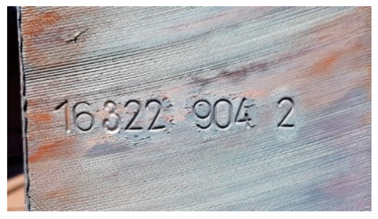
Steel billets have, for identification purposes, a serial number, which is created by a marking automatic machine immediately after the billets exit from the continuous casting machine.
The numeric character contains a combination of 5 to 9 digits, possibly accompanied by two letters.
The steel billets are arranged on the charging grate and individually conveyed to the heating furnace.
For the purpose of billet identification, the possibility of digitizing numerical characters on the computer monitor of the operator’s station and the possibility of archiving the obtained information is required.
The selection of technical means for scanning and subsequent identification was made with regard to the properties of the scanned objects, which were steel billets. The dimensions of the billet are 8 m in length, 150 mm in width, and 150 mm in height. The weight of one billet is approximately 2 tons.
The billets are arranged on a loading grid and individually transported to a heating furnace, from which they continue to the rolling line after reaching the required temperature. For identification purposes, they are marked with a serial number string, which is created by an automatic stamping machine on the front of the billet. The numeric character contains a combination of 5 to 9 digits, possibly supplemented by two letters. The basic components were an industrial camera, a camera lens, a camera cover, a camera cover holder, a power supply, a light reflector, and related cabling. When choosing an industrial camera and accessories, it was necessary to take into account, in particular, the method of use and the properties of the environment. Components must be designed for continuous operation in an industrial environment. Also, the emphasis was on reliable operation, software, and reasonable price. Based on these conditions, the camera IP 1343 was selected by Axis (see
Table 1 for parameters) and lens Computar TG10Z0513FCS (see
Table 2 for parameters).
Due to the production environment having both high temperatures and considerable dustiness, it was necessary to place the camera in a camera cover. This cover protects the camera from dust, moisture, and mechanical damage. The type used is TP607H protection class IP66, it is designed for a temperature range from −30 °C to +50 °C. The cover was mounted on a bracket equipped with a swivel joint that allows the camera cover to be swiveled and tilted to the desired position.
Camera power was provided by a linear 12 V/800 mA stabilized power supply. The power supply was placed in the camera housing using a cover kit.
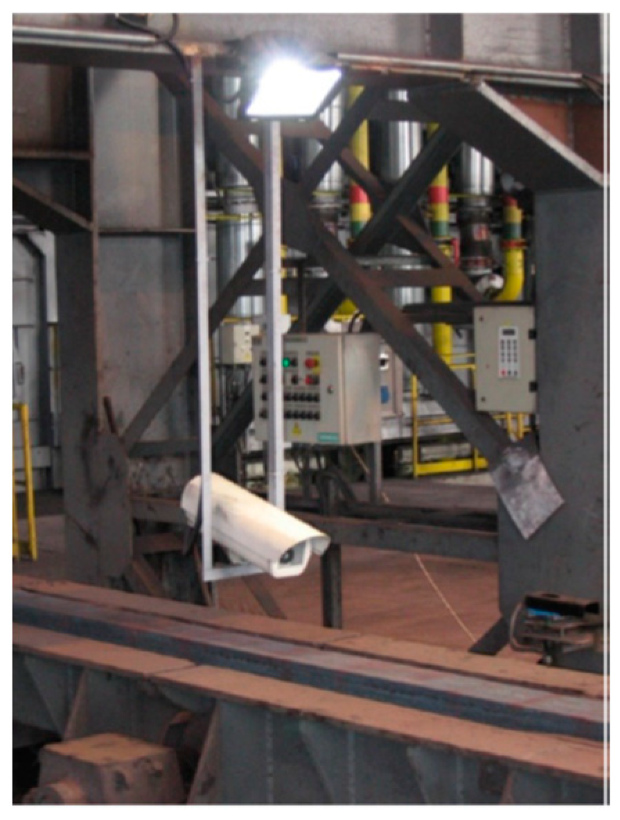
A bracket was made to mount the camera housing, welded from L-type steel profiles 40 mm × 40 mm with dimensions of 300 mm × 1000 mm, and treated with gray paint, see
Figure 1.
A halogen reflector with a power of 100 W was used to illuminate the billets.
Interconnection of network camera and data network was solved by FTP (Foiled Twisted Pair) (cable category 5e, cable CYKY-J 3 × 2.5 was used for power supply of camera and lighting. Existing cable routes were used to store the cabling.
Pre-installation settings and installations of network cameras, network camera settings, lens testing, and network communication, as well as power supply functions, were performed. The camera was connected to a power source and a network cable to connect it to the computer. The camera was configured using a web browser. The network address, netmask, and gateway address were set on the camera. Then the administrator password was set. After these steps, it was necessary to restart the camera to save the newly set values. Camera configuration continued by setting the time zone, current time, and time synchronization server time. The next step was to adjust the image quality and resolution. The image quality and resolution were set to maximum, MJPEG was selected for the video format. The camera was equipped with a lens and several focusing were performed, including the extreme positions of the lens. This was followed by testing the auto iris function by aiming the camera at dark and light places alternately. In this way, the camera, lens, and power supply, i.e., the components that have the greatest impact on the final image quality, were easily tested.
The camera, including the lens and power supply, was placed in the camera housing to which the hinge bracket is attached. The location of the camera installation was chosen with regard to the production technology, optical possibilities of the camera, cable routing, and camera testing. A bracket for the camera cover was welded at the selected location, and a light reflector with a power supply terminated by a double metal socket with IP 55 protection was placed above the console.
The camera was placed in the center of the conveyor approximately 30 cm above the passing billet, as shown in
Figure 2. The scanning distance with respect to the required details and lens capabilities was determined by a camera test approximately one meter from the camera lens.
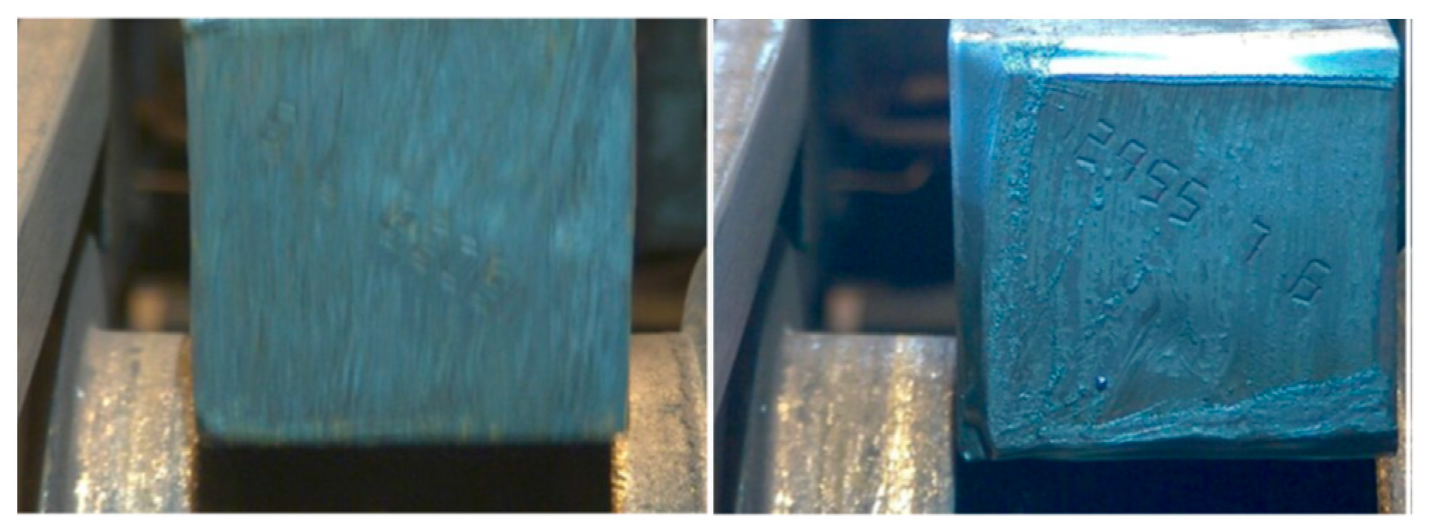
During camera tests, it was found that it is not appropriate to scan billets in motion (
Figure 3), especially because the effect of transmitted vibrations, which cannot be completely eliminated, significantly impairs the image quality. Much better results are achieved by scanning billets at rest. Based on these findings, it was necessary to stop the passing billet at a given distance from the camera before saving the image.
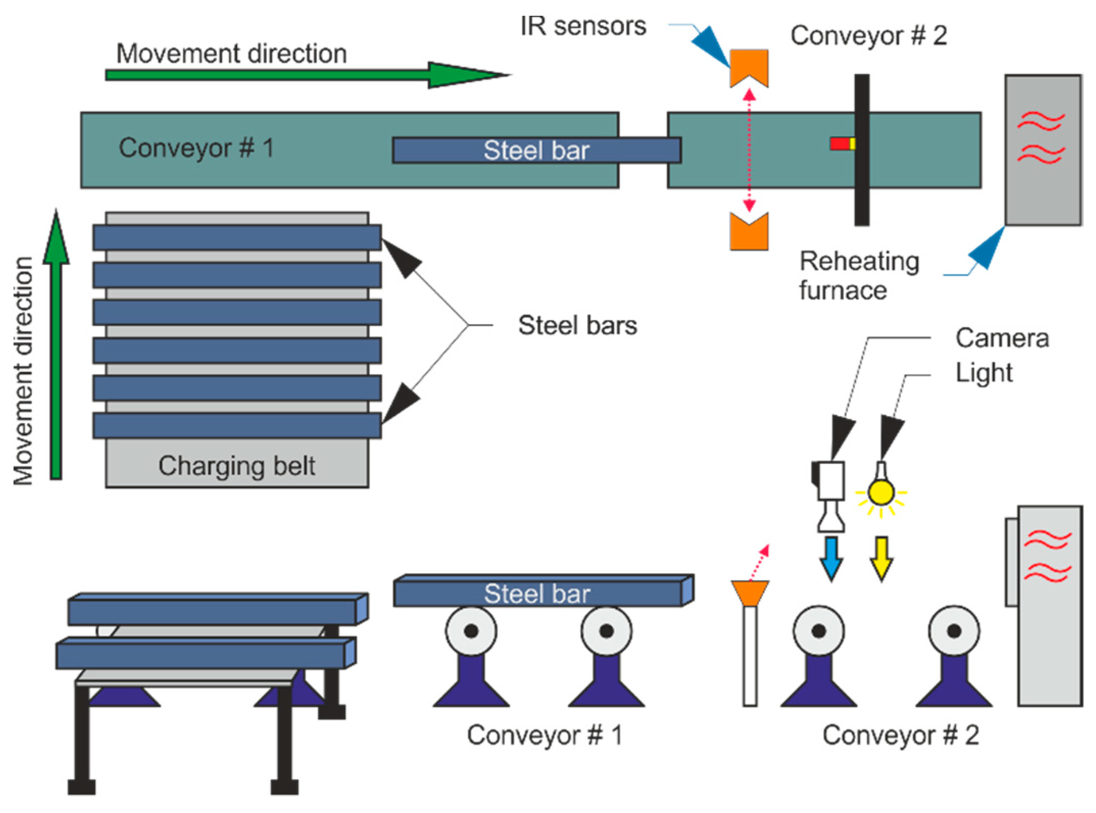
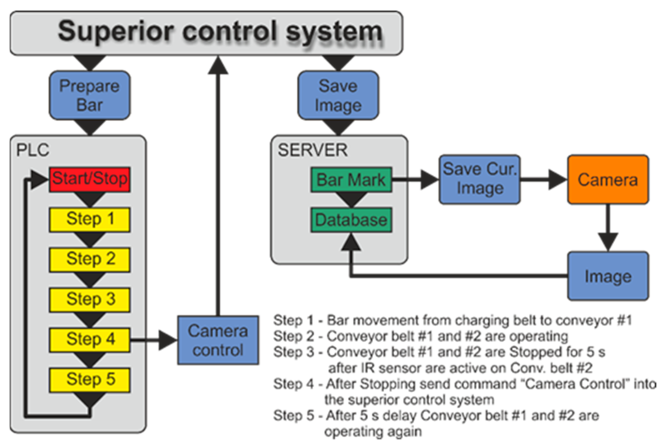
The rolling of the billet is controlled by a programmable logic controller (PLC) Simatic S7 300. This PLC controls the movement of semi-finished products on the charge grate and conveyors on which the semi-finished products are transported to the heating furnace. The PLC program for conveyor control had to be modified so that the billet stopped at the specified location, at this point the required time remained and continued to move to the heating furnace.
The start command for the PLC is the “prepare billet” command from the main control system. The movement of the billet from the filling grate to the heating furnace takes place in the following steps, which are also shown in
Figure 4.
Transfer of billet from charging grid to conveyor No. 1.
Start conveyor travel 1 and 2.
Stop the conveyor No. 1 and 2 for 5 s after signaling the sensor on conveyor No. 2.
After stopping, send the “stop camera” command to the master control system.
Start the conveyor travel 1 and 2 after 5 s.
The following new commands have been added to the sequence of commands in the PLC control program:
Travel stop after sensor signaling from conveyor No. 2.
After stopping, send the “stop camera” command.
After 5 s, start conveyor travel 1 and 2.
All these changes were made in STEP 7 version 5.5. The billet stop sensor was used by the LT 100L and LR 100L in a light barrier with a PA 11B evaluation unit from Telco. This solution excels above all in its high vibration and dust resistance.
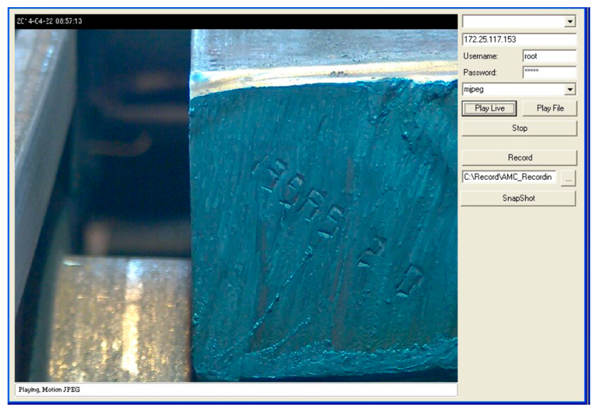
Camera control and image storage were performed using the Axis Media Control SDK development software (version 6.32), which is available on the Axis camera manufacturer’s website. With the help of this software, a program was created to control the functions of IP cameras. The program was run on a camera server, which was equipped with enough memory to store images. The driver was created in Visual Studio 2010 express and C #. This programming language created a program with a simple graphical interface called Punching Billets, see
Figure 5. The graphical interface contains several function keys that can be used to call up the respective camera and program functions. After starting the Billet Punching program and displaying the graphical interface, it was necessary to set the data for communication with the IP camera. These include the IP address of the camera, the login name, and password of the camera administrator, the type of video playback (with options between MJPEG, MPEG 4, and H.264), and the recording path. After pressing the Play Live button, the program establishes communication with the IP camera, verifies the login name and password, and displays the current image from the IP camera in the preview window [
5,
6].
Creating a snapshot was done by calling the Save current image function in Billet Stamping. The function creates an image in the camera and saves it according to the set path. This function is also available directly in the graphical interface on the SnapShot button. Several functions have been programmed using the graphical interface buttons, such as the already mentioned Play Live function, the Play File function which plays the video stored on the server, the Recording function which starts recording the image from the camera and saves the recording according to the set path, and the Stop button which activates the function to stop the current operation, i.e., play the current image or play the saved video. The possibilities of the program are very wide and allow you to control a large number of functions and control the connected camera. The described billet identification system mainly uses the image saving function. Other functions are mainly used to test the system. The Billet Punching program can also be controlled using commands and this option is used in the described image storage system. The camera server receives a command to save the image from the parent controller and invokes the image storage function in Billet Punching to create the image and save it according to the set path. The component of the Save Image command is the billet ID that is used for the image name.
Saved images are accessible through the production information system to users with the appropriate permissions. Image archiving was set for at least two years.
3. Testing the Optical Recognition of Characteristics
A partial goal of the solution was to test the optical character recognition. The commercial programs Abbyy Fine Reader version 12 and Free image OCR (Optical Character Recognition) were used for this purpose. These programs allow you to convert text from a photo to plain text format. Twenty images from the billet identification system were selected for testing. Selected images were tested in the mentioned programs. All tested images were in JPEG format and the programs were set to save in txt format [
7].
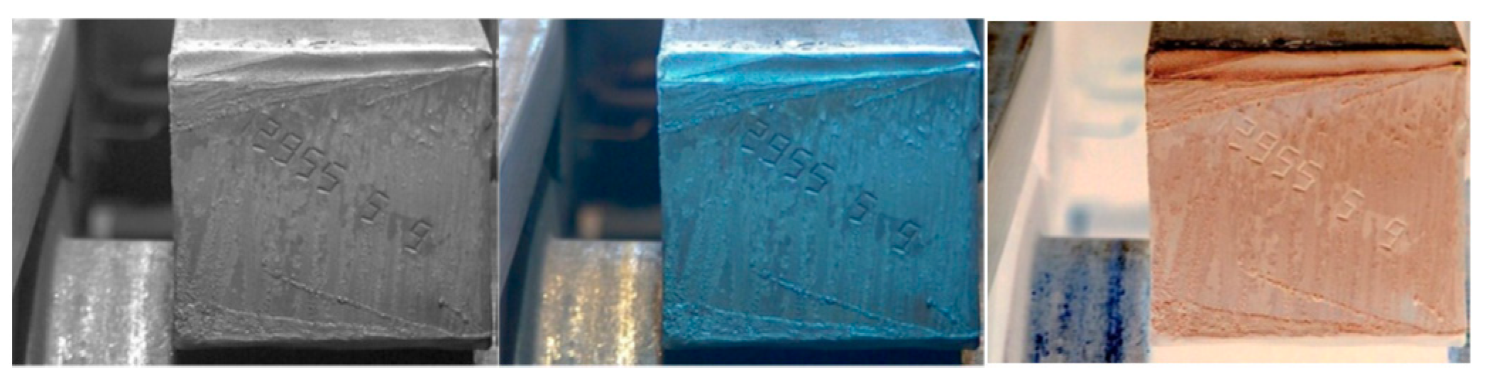
In the first phase, the images were tested in their original colors (
Figure 6), followed by black and white images (
Figure 6), and in the final phase, the images were turned into negative colors (
Figure 6). Each image was tested separately. The test results in these programs were insufficient. Changing the color spectrum also did not produce better results. The programs could not recognize the billet numbers from the tested images and also did not export satisfactorily to the txt format. The basic problem was the high error rate caused by the automatic vectorization of the OCR evaluation software. With automatic vectorization, the software must be able to determine the basic entities that make up an image based on the color information of each pixel. When applied to embossed characters on billets that contained many different OCR deformations, the software did not perform well. The introduction of pre-processing tools would improve this situation.
3.1. Machine Vision
Computer vision is one of the most advanced areas of computer technology. Used to recognize the required information from the image captured by the industrial camera, computer vision is widely used, especially in the industrial sector, where it is referred to as machine vision [
8].
Computer vision basically replaces human abilities in terms of understanding and interpretation of the image by technical means. Typical tasks in machine vision may be the recognition and counting of products using industrial cameras, positioning, dimensioning, or optical quality control. In conjunction with other product handling systems, some manufacturing operations can be fully automated using machine vision systems.
The basis of a reliable machine vision system is suitable illumination of the scanned scene in which the scanned objects are located [
9]. The image data obtained by a scanning device, such as a digital industrial camera, is then processed by the system to recognize the desired information. The system is connected to other control parts of the production line, as required, with which it communicates and can autonomously intervene in the production process or provide signaling to the operator. From automated interventions, we can consider stopping the machine, discarding defective and poor quality products, rotating parts in inappropriate positions, etc. Access to the system can also be enabled remotely via an application or web interface.
Machine learning methods have been used to improve computer vision to identify embossed characters. There are many such methods, for example [
10,
11,
12,
13,
14,
15], which have certain limitations. In [
16] off-line character recognition is presented, which is applied to the billet identification system in the steel industry. Identification characters are so damaged in this application that we need noise-resistant methods and robust character segmentation and extraction algorithms. We propose new local methods of adaptive thresholding and character extraction. We use a subspace classifier using KLT (Karhunen–Loève Transform—principal component analysis—robust pattern recognition method) to classify characters. The methods have been tested on real industrial applications and have proven to be successful and allow implementation in technological processes.
Unlike the above publications, the proposed machine learning solution for the identification of embossed characters is unique to the metallurgical industry and works online in real-time. The basic difference is in the method of finding characters and thus in the identification of the whole string at the head of the billet and in the method of learning the character, where only selected pixels are used for learning and therefore not the whole pattern. This approach allows the chosen principle to be used to support real-time play and for control models that must be simple, fast, but also accurate. Another difference is that even though no filter is applied in the method when digitizing the billet face, the method is completely accurate.
3.2. Techniques to Reduce Character Reading Error
An image may contain (and usually does) contain certain errors, whether it is the input device (camera), the surface of the material, or the imperfections of the characters themselves. Some of the main errors and ways to eliminate them are [
17]:
Removal of stains—This is a basic process for reducing error rates. Spots are usually caused by the dirty surface of the sensor (camera). The most effective method to stop this error is prevention, by regularly cleaning the camera lens and general hardware scanning. Once this error is embedded in the resulting image from which the characters are to be recognized, the solution is more complex and is carried out similarly to the recognition of the characters themselves—instead of characters, the spots are recognized according to the pre-learned shapes.
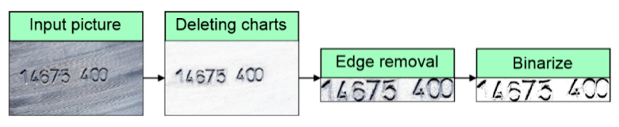
Deleting tables and charts—These “bugs” are mainly contained in various forms and documents that contain a large number of frames and objects that enhance the clarity of a person when filling in them. For the text recognition algorithm, however, the existence of these elements is very poor and often leads to improper detection. Therefore, it is necessary to remove the table and the various lines (which are clearly detected as lines, not as part of the letters) before the text is recognized.
Edge removal—Ideally, the camera is turned on the product so that the edges are as small as possible. However, this is often not possible, so the edges are erased by software. The existence of the margins does not have to mean a malfunction of the algorithm that detects the characters, but greatly simplifies the work and reduces the number of cycles the algorithm has to manage. At the same time, this change in the size of the surveyed pattern will positively affect other processes that will run much faster.
Color adjustment—The text recognition algorithm works based on an image input with a unique color spectrum that can be logically converted into two states—the pixel is the text or the pixel is the background. Of course, this is a very simple formula that applies only to machine-typed texts on a perfectly pure background. The main color treatment is so-called binarization. In this process, each individual image pixel is converted to logic 1 or logic 0 according to defined decision levels (for colors, these are practically three different decision levels for the RGB (Red-Blue-Green) spectrum). The output of binarization is then a black and white image that can be presented as input to the text recognition algorithm.
Alignment of the font tilt—This error can be defended against in two ways. The first is to build an algorithm that will be used to straighten the characters. Such a method may be more demanding to implement, and it can irritate the characters irreversibly so that they cannot be recognized. A simpler and more efficient method is to increase the training set and incorporate characters with different slopes. Detection will take place just as with straight text [
2,
3]. The input image editing process for the character recognition algorithm is shown in
Figure 7.
3.3. Algorithm of Optical Detection of Character Positions
A sequence of algorithms was created in the MATLAB programming environment, which will take care of the individual processes of editing the input image. The result of this sequence is information about the distribution of characters in the image—their number, coordinates, and size. Individual characters will be used to recognize the entire text separately. There are also types of OCR that are able to compare whole words. This solution can be more effective for short words, for longer words it can be a problem to find a suitable pattern. It is also more difficult to deal with the inclination of individual letters (some are inclined, others are not). Full-word comparison can be used where input is expected in some way, such as reading forms where answers are repeated frequently or are dependent on padding, depending on the options in the defined options menu. In this case, the recognition speed is much slower than when sequentially decoding characters.
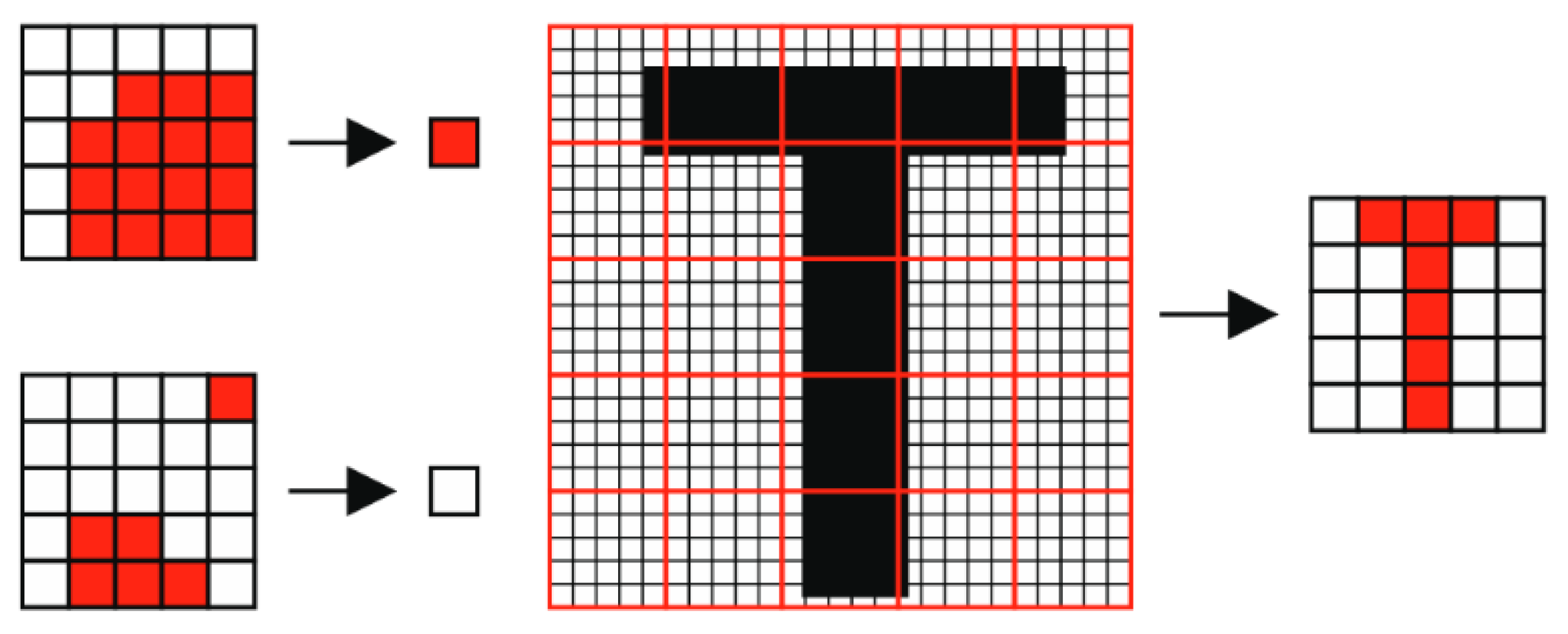
You must first resize the input image. In many cases, the image is too large due to the high resolution, so it is necessary to reduce it in order to significantly speed up the whole process of editing the input and its subsequent recognition. To resize an image, MATLAB has a simple function, but because it is the purpose of creating atomic algorithms that are transferable between different programming languages, it is necessary to define and create your own function for this purpose. The algorithm works by dividing the image into arrays of 5 × 5 pixels. From each matrix, it calculates the amount of color contrast that is input to a new thumbnail, where it represents 1 pixel. The principle of the process can be seen in
Figure 8 [
3].
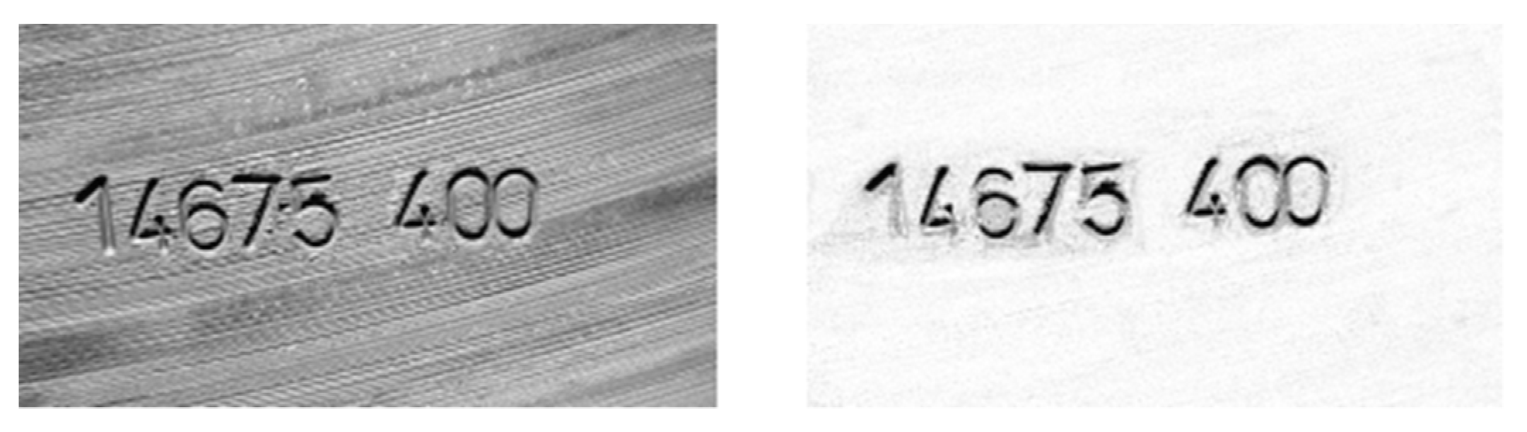
This reduced image is ready for the next process, which is to reduce the reading error. Stains and lines are removed here. The principle of this process is often called a mask. A mask is an image that contains a shape (line, circle, polygon) that is compared to an input image, then overlays both images and removes the corresponding parts. An example of the output after using the line elimination mask is shown in
Figure 9. This adjustment will significantly increase the success of character position detection and its later recognition. For demonstration, the output of the algorithm from the original and modified image is displayed in all procedures [
18].
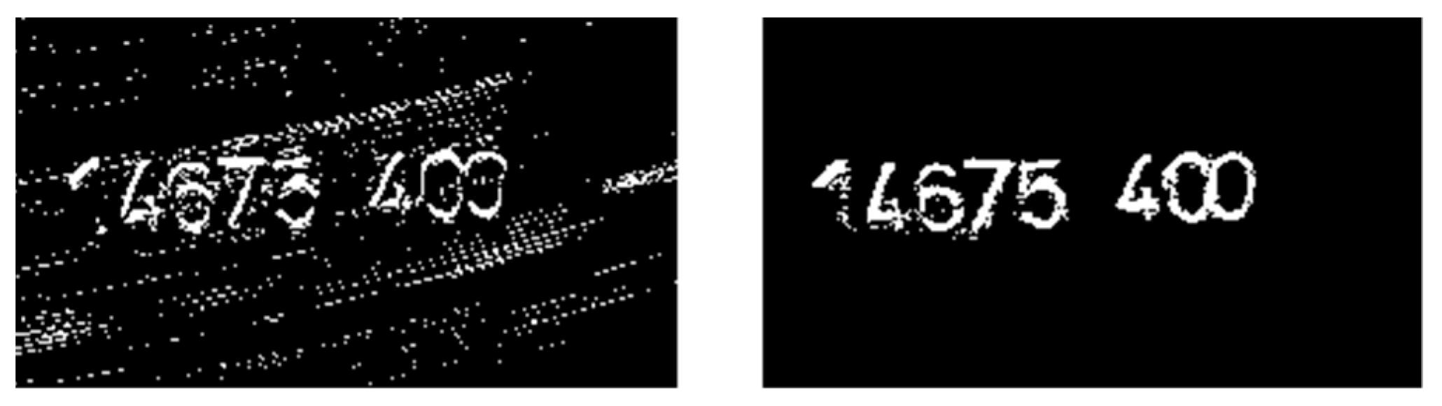
After editing the image, the image should be cropped to the edges. In this case, however, this step is omitted to better display the character position detection algorithm. The next step is to binarize the image. In the case of a good background (surface), a simple binarization is sufficient, where each pixel is compared with a certain level, which indicates whether the output pixel is 1 or 0. However, for images with a bad and noisy background, the rating would be too poor to work. Therefore, multiple algorithms have been developed that perform other types of binarization. The outputs of all these algorithms are evaluated and one binarized output image is created for the work. The output binarization for the input and the edited images are shown in
Figure 10 [
19].
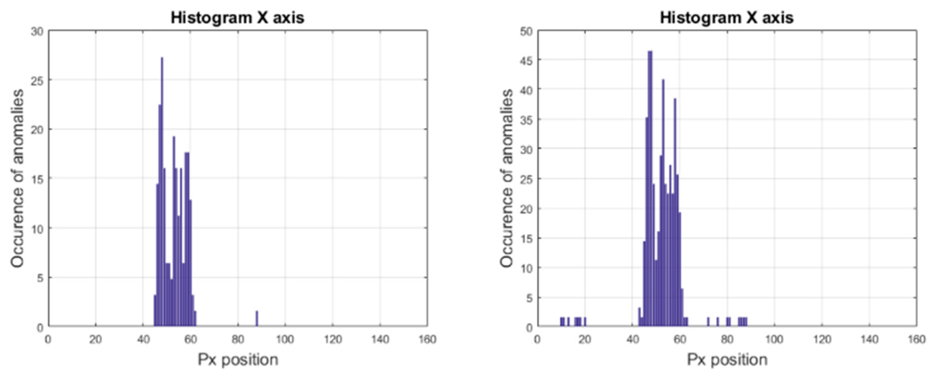
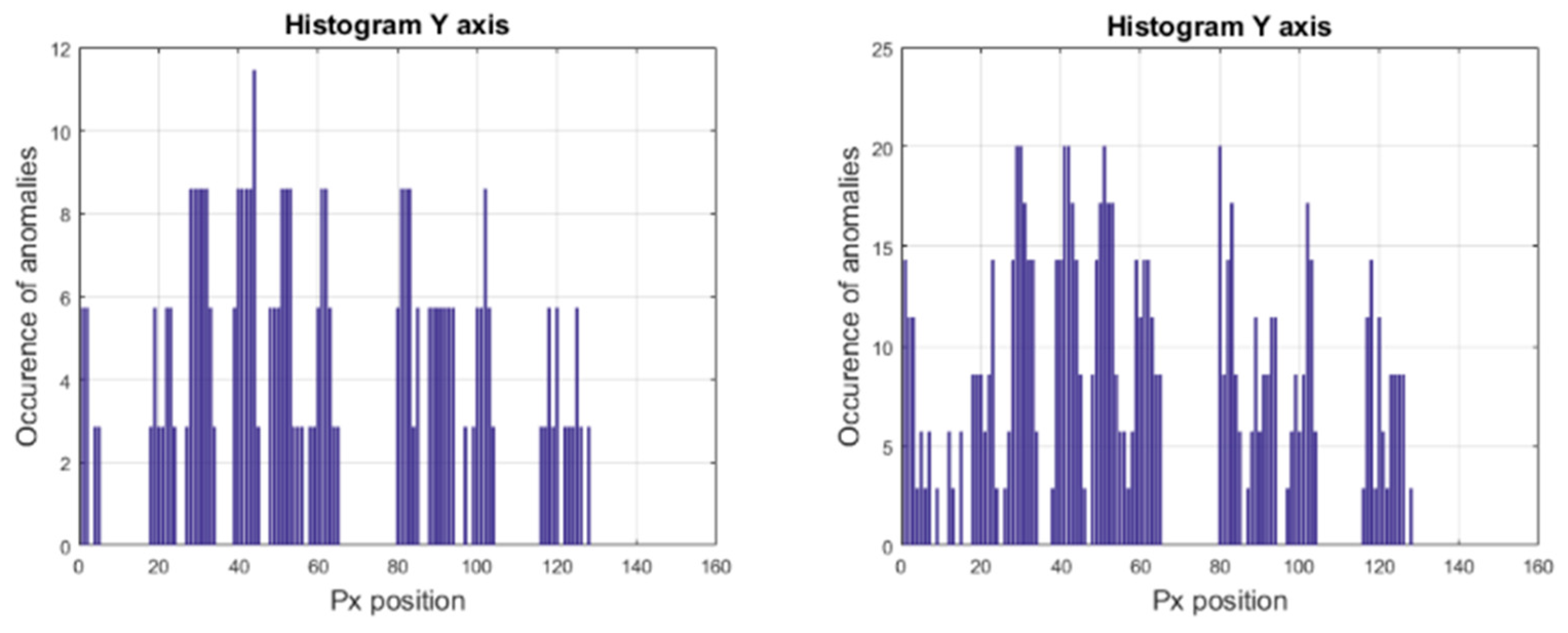
The position of the characters can be detected from the binary image. The sum of pixels in the
X and
Y axes is performed in the algorithm. This sum is then compared to a decision level that determines whether the axis is noise or a character, i.e., whether the information should be discarded or considered a result. The histogram of the
X-axis anomaly is shown in
Figure 11 and
Figure 12 is a histogram of the
Y-axis anomaly.
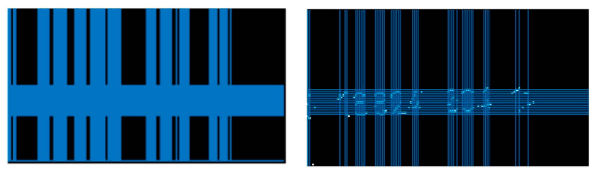
By linking the pixel sum information in each
X and
Y axis, this information can be plotted in the image. Line overlap on lines
X and
Y reduces the occurrence of characters. As seen in
Figure 13, the unedited input image evaluates the position of the characters with very low accuracy.
This output is difficult to use as input for a character recognition algorithm. On the other hand, a modified image that has removed typical features that reduce its quality shows great accuracy in recognizing character positions.
4. The Use of Neural Networks for Machine Vision
An artificial neural network can be used to recognize the attached patterns from the image. It serves as a classifier based on associative memory. Images of sent patterns are stored in net weights and the attached pattern is a response to the attached pattern [
20]. The distribution of the network is solved according to the topology of the neural network and the number of outputs. One input layer neuron corresponds to one image pixel. The neural network works in two basic phases [
7]:
Learning phase: (a) adjusting weights according to input patterns; (b) repeating the learning process.
Triggering phase: (a) placing an unknown pattern on the input; (b) initializing the state; (c) iteration until the answer is found.
For pattern recognition from an image, a series of different types of neural networks can be used, for example, the Hopfield network, Kohonen’s self-organizing network, or multilayer perceptron neural networks that are used in our solution, etc. [
10].
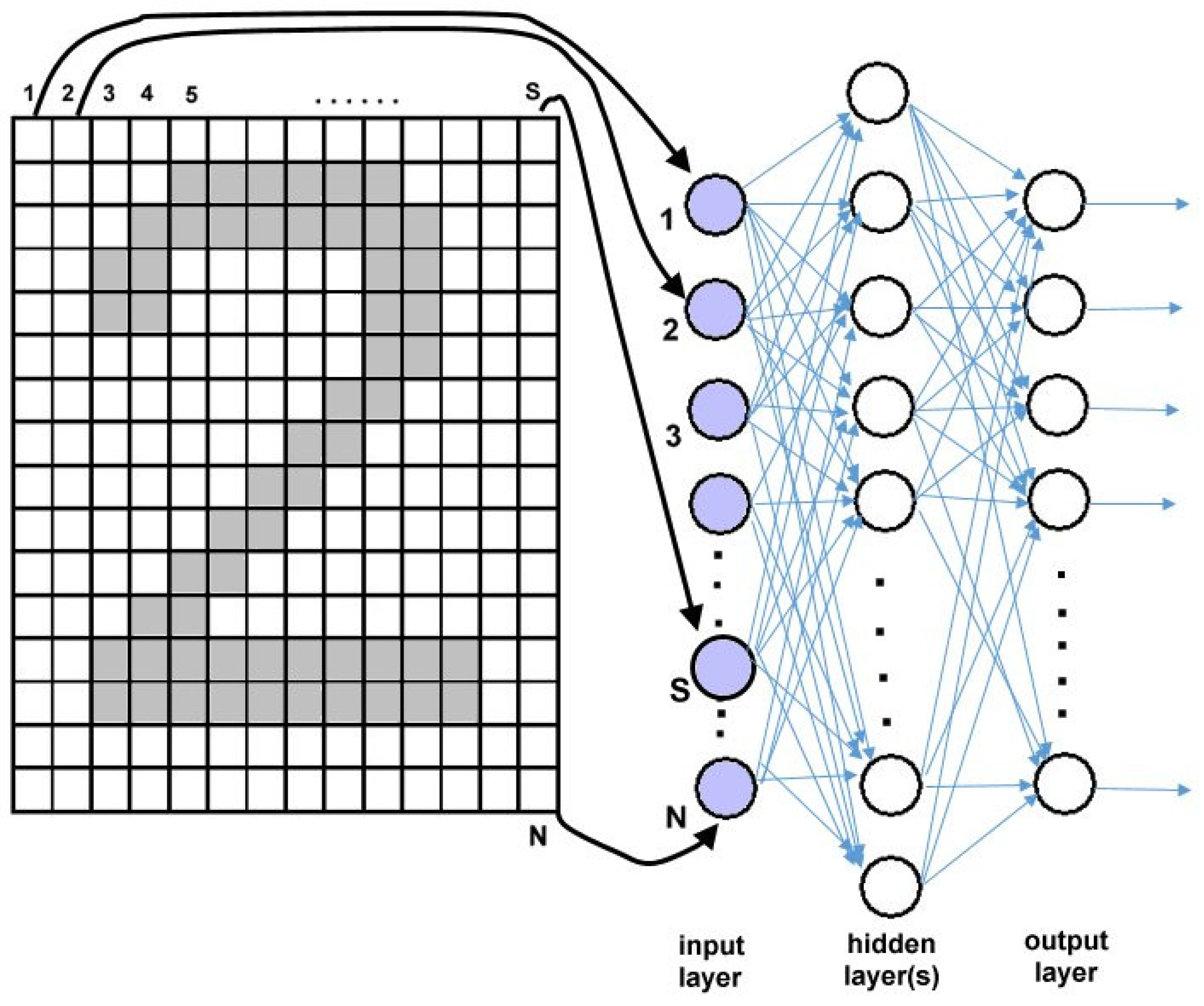
4.1. Digit Image Classification
The shape of the digit is described by a binary image, each pixel corresponding to one input of the neural network. Therefore, the input layer is equal to the image resolution (
Figure 14).
However, associative memory does not guarantee invariance to scale, rotatation, changing the font, noise, etc. Independence from these phenomena can be achieved by using artificial neural network approximation classifiers with a suitably selected training set [
17,
18].
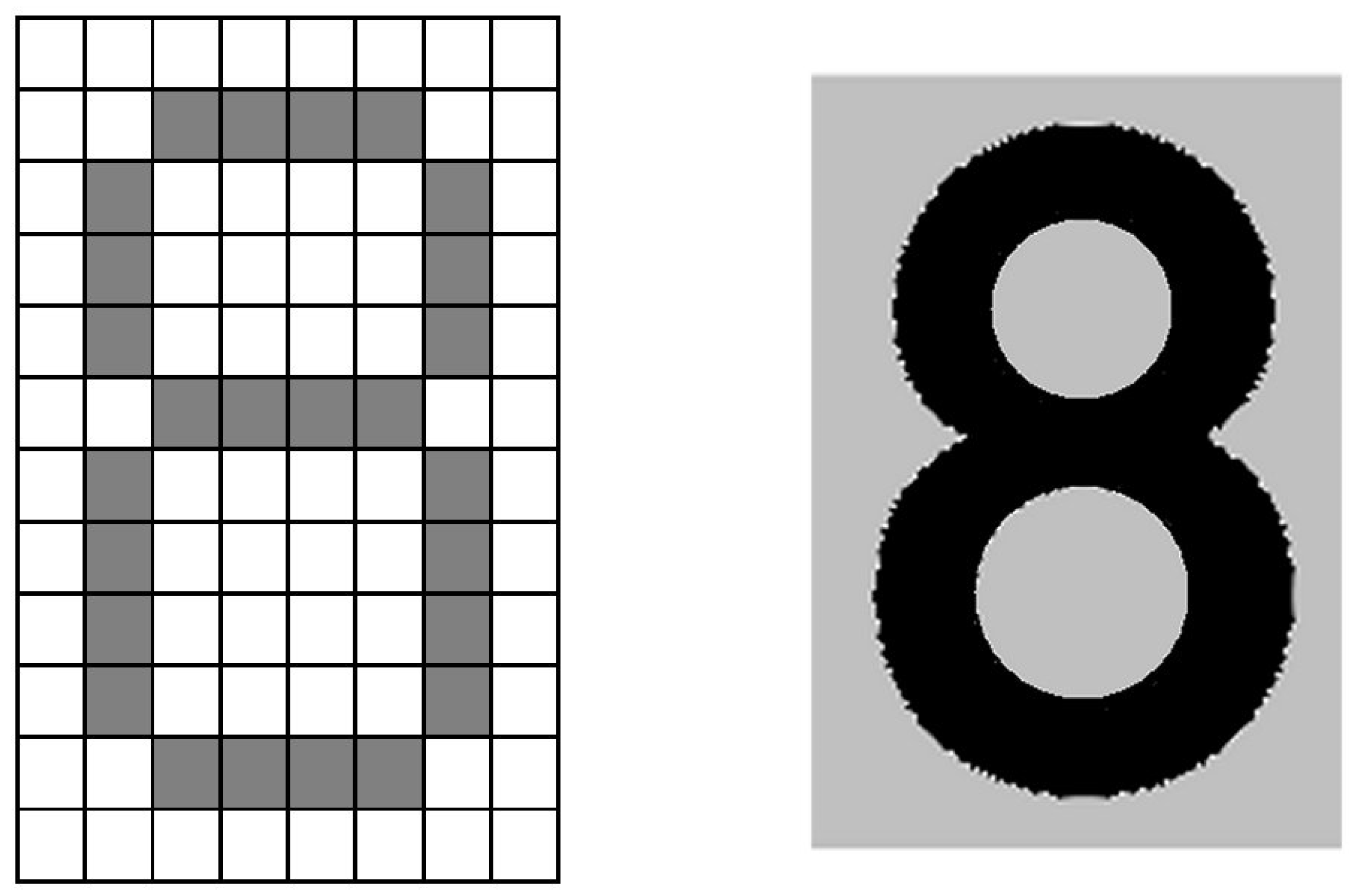
The character is represented by a matrix of zeroes and ones (
Figure 15 left). Each such function is an ideal case of a real image of a character (
Figure 15 on the right).
In the character recognition task, the individual lines of the character pattern are arranged one after the other and represent a single line pattern.
4.2. Automatic Identification of Embossed Numbers on Continuous Steel Casting Billets
It was necessary to create a method using an artificial neural network. For the learning process of such a neural network, a training set of photographs of the fronts of billets with identification strings was created. An example is shown in
Figure 16. The identification strings were divided into individual characters to create a training set for identifying individual characters. The training set for this testing contained 45 patterns in the original, black and white, and negative colors with numerical characters on the billets.
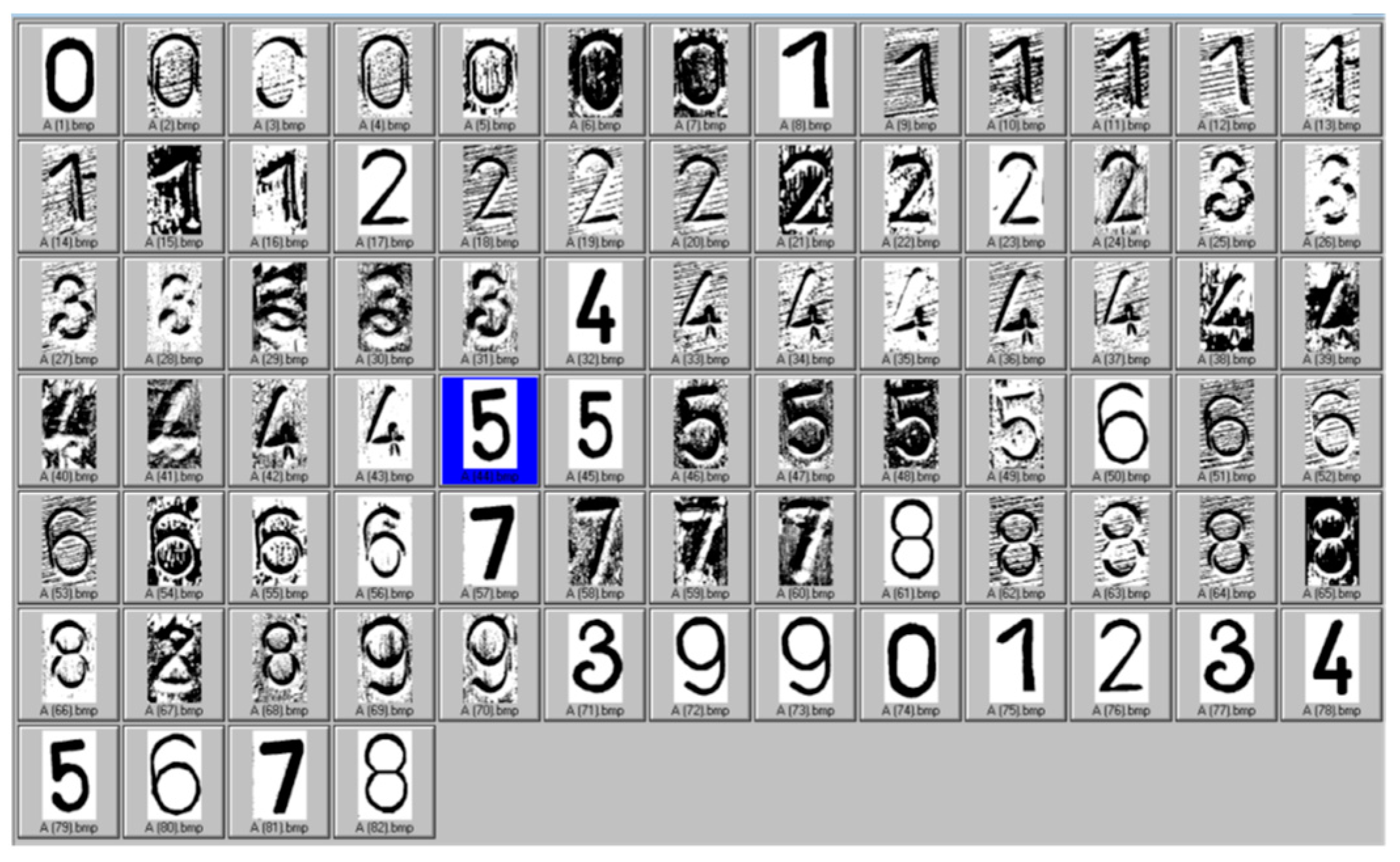
The individual digits (
Figure 17) are separated from the pictures of the billets, which form the basis of the training set for learning the neural network [
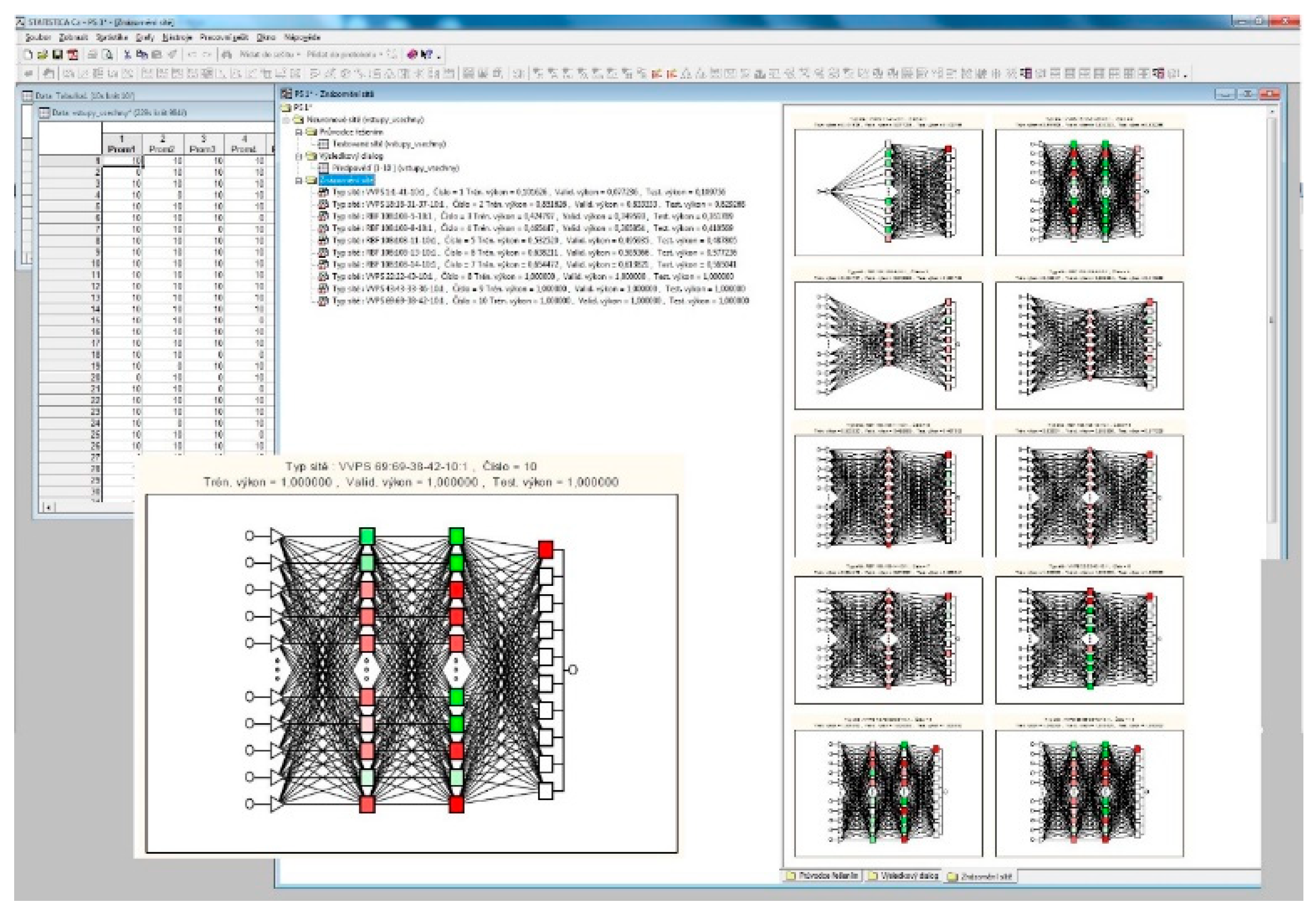
8]. The neural network was created in STATISTICA.
Figure 18 shows the STATISTICA software screen with visualization of selected neural networks that were tested.
The result of the solution was to find a multilayer perceptron’s neural network with topology (VVPS) with topology 69-38-42-10 and the backpropagation method was chosen for her teaching. The network topology was generated by the neural network module of the STATISTICA software within the learning process. STATISTICA software generates a specified number of neural networks of a predefined type, but with different topologies and provides the user with an overview of generated neural networks with learning parameters (training performance and learning errors). The user then selects a suitable neural network.
The identified character is interspersed with a mask that contains 69 pixels. These pixels form the entrance to the neural network. The resulting neural network was subsequently transformed into C # programming code and is the basis of an emerging industrial application.
The neural network was designed and tested for automatic identification of embossed numbers, although it does not suppress background noise and therefore does not perform pre-processing and segmentation, which greatly simplifies the solution and speeds up the final processing while maintaining 100% classification of embossed numbers. This is also achieved by the fact that the system is conceived as open and the training set is supplemented by other patterns with subsequent re-learning.
The proposed system of automatic identification does not reduce the production cycle of technological processes, as the process is not continuous and provides enough time (approximately 2 min) for the entire processing. The proposed algorithm provides digital information in a matter of seconds (the exact time was not measured).
Although the system enables auto-associative processing of embossed numbers, situations of misidentification occur (of the order of 0.01%), which are, however, caused by the non-embossing of the symbol in the identification chain and thus by the error of the previous technological process.
5. Conclusions
This article presents a partial part of the machine vision system for automatic identification of the character string of billets on the rolling mill line. The system enables the conversion of image information from the front side of the billet into a character string, which is further used to control the technological process of rolling and to archive the process parameters. The identified character string here serves as a unique identifier of the billet. Currently, all parts of this control system are in full operating mode.
The creation of this system was started on the basis of operational requirements, due to higher automation of operation and ensuring the control of steel billets according to the production plan. The machine vision system uses a camera to scan the area in front of the furnace and allows automatic inspection. The output of the described part of the system is digital information of numerical characters on the computer monitor of the operator’s station and enabling archiving of the obtained information. This reduces the operator’s workload and reduces manufacturing errors. The identified character string is the result of a system of an algorithm for automatically identifying the character string and individual characters and an algorithm for automatically digitizing individual characters.
Heuristic algorithms for finding the identification chain in combination with multilayer artificial neural networks of the perceptron type with topology 69-38-42-10 were used for automatic identification of embossed numbers.
A training set of photographs of the fronts of billets with identification strings was created for the learning process. The identification strings were divided into individual characters, thus creating a training set for the identification of individual characters. The training set for this testing contained 45 patterns in the original, black and white, and negative colors with numerical characters on the billets. The application of artificial neural networks in the field of image processing is not new, but the uniqueness of the proposed solution lies in the modification of this processing, which results in a significant simplification. The designed and implemented algorithm for automatic identification of embossed numbers does not suppress background noise, so it does not perform pre-processing and segmentation, which greatly simplifies the solution and speeds up the final processing while maintaining 100% classification of embossed numbers. These side effects are eliminated by the proposed neural network. The proposed system of automatic identification does not reduce the production cycle of technological processes, as the process is not continuous and provides enough time (approximately 2 min) for the entire processing. However, the proposed algorithm provides digital information in a matter of seconds and is therefore usable in continuous processes.
Although the system enables auto-associative processing of embossed numbers, situations of misidentification occur (of the order of 0.01%), which are, however, caused by the non-embossing of the symbol in the identification chain and thus by the error of the previous technological process. The whole solution was done on real pictures. This solution is an example of the digitization of technological processes, which is reflected in sustainability in the social and economic field. This example of a solution also shows the possibilities of artificial neural networks and other methods of artificial intelligence, in general, to solve complex problems in industrial and non-industrial environments. The proposed solution is unique for the following reasons:
- -
it is applied in a metallurgical environment, which shows large differences in digital image processing (impurities, lighting, heterogeneity of shapes and surfaces, specific temperature conditions, etc.);
- -
the method can find the character string on the face of the billet;
- -
the method can identify a character without the use of a filter in digital image processing;
- -
the method identifies the character, while only selected pixels of the character are used for learning, which enables real-time work;
- -
the method is accurate and fast, which allows it to be applied to decision support, process management, or quality control systems;
- -
the method works using standard hardware and software.
This solution is an example of an innovative approach to the issue of digitization of technological processes, which is reflected in sustainability in the social and economic field.


