
Significance of Enhanced Oil Recovery in Carbon Dioxide Emission Reduction


Abstract
1. Introduction
2. Methods
3. Captured CO2 Utilization
3.1. CO2 Conversion
3.2. Direct Use of CO2
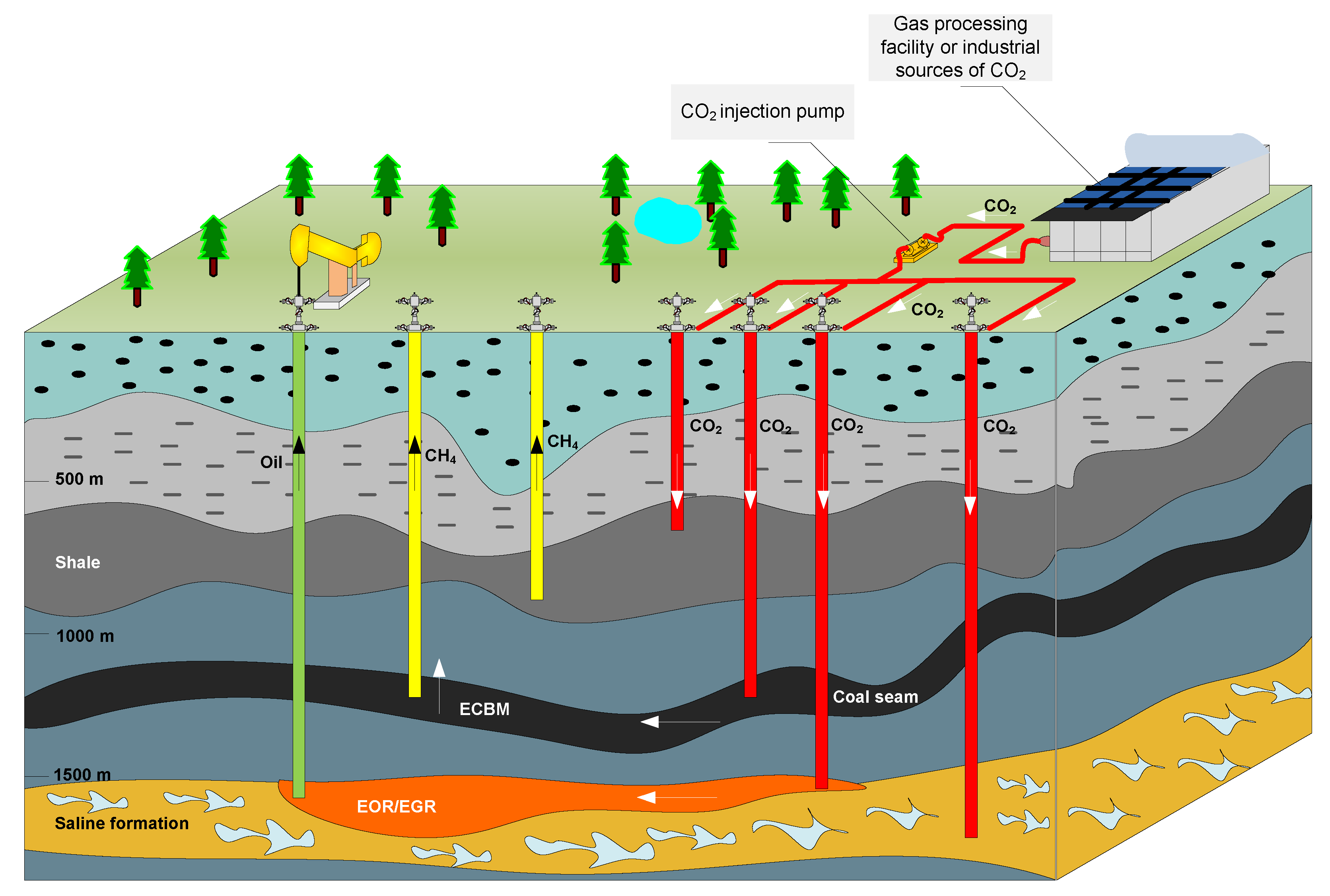
4. Enhanced Oil Recovery by Injecting CO2
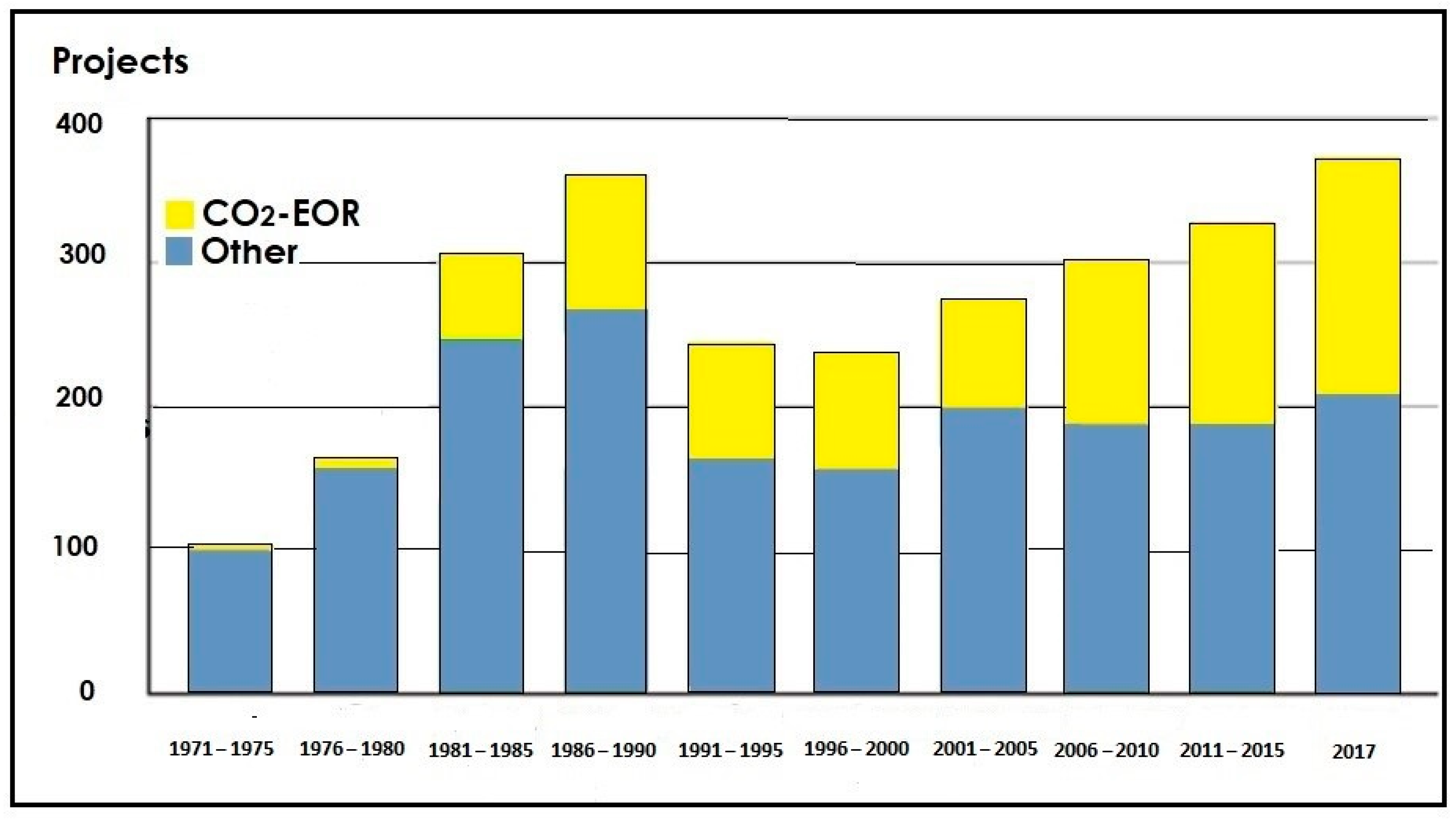
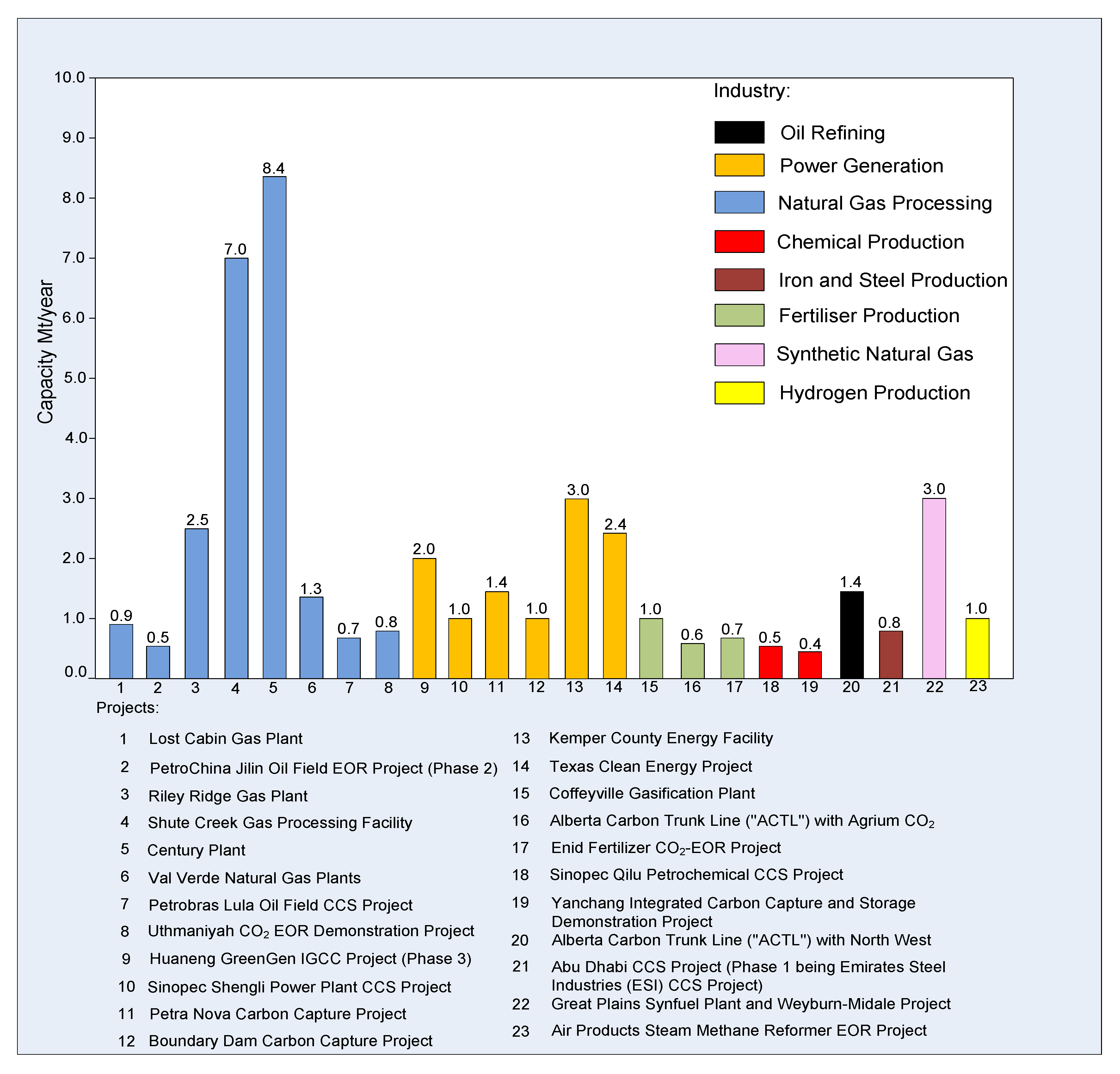
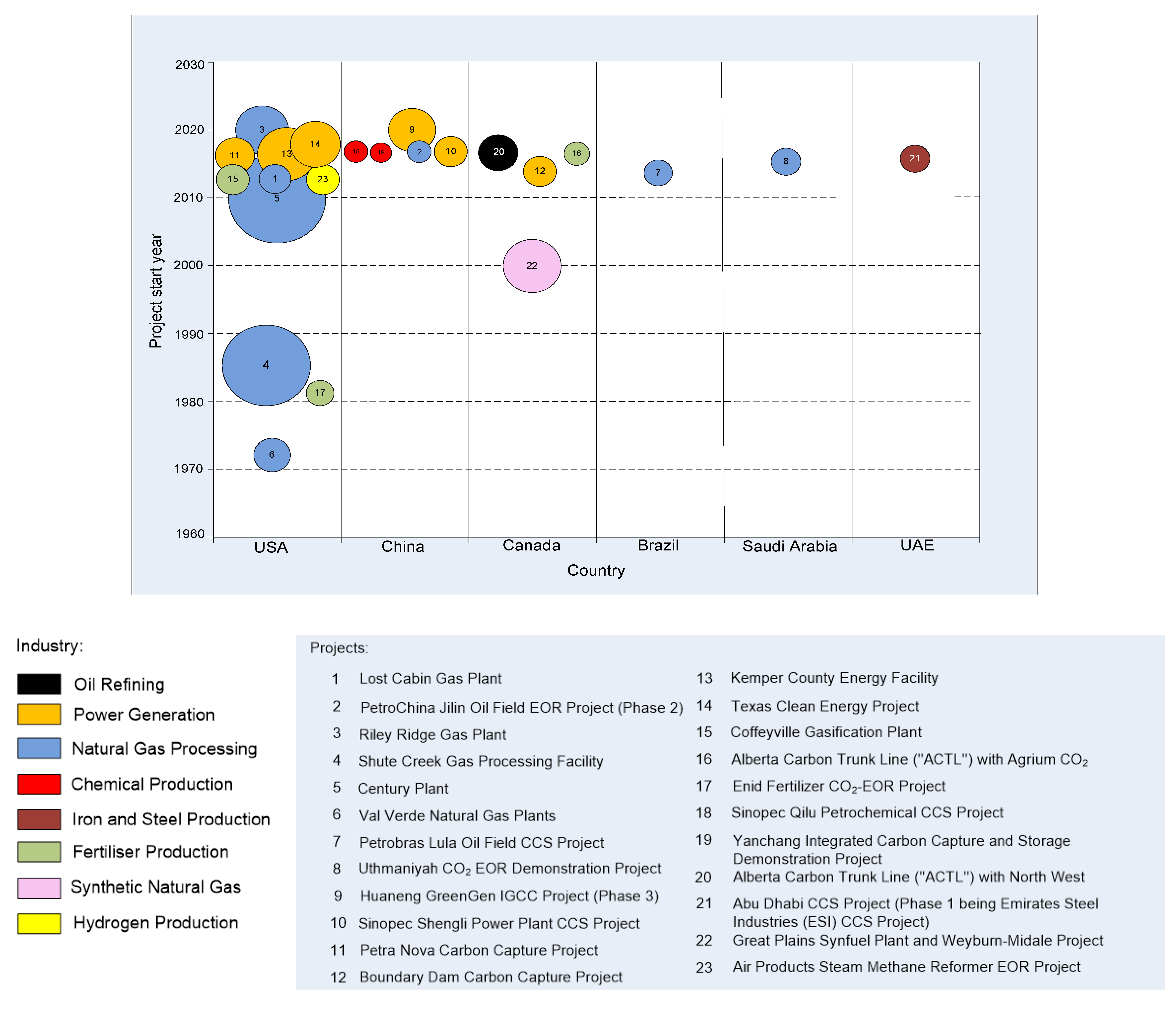
An Overview of CO2-EOR Projects in the World
Large-Scale CO2-EOR Case Studies
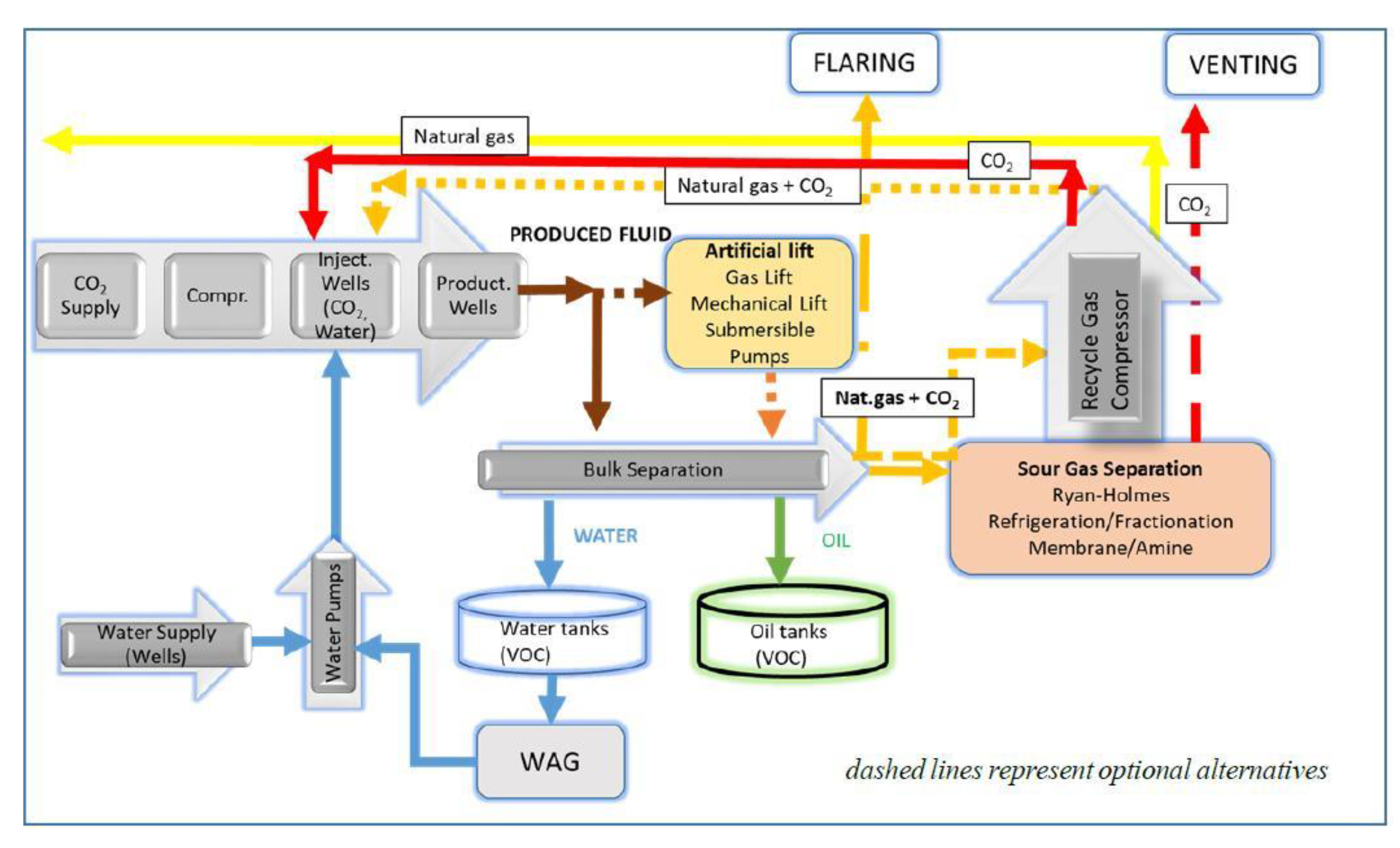
5. CO2-EOR Site Emissions
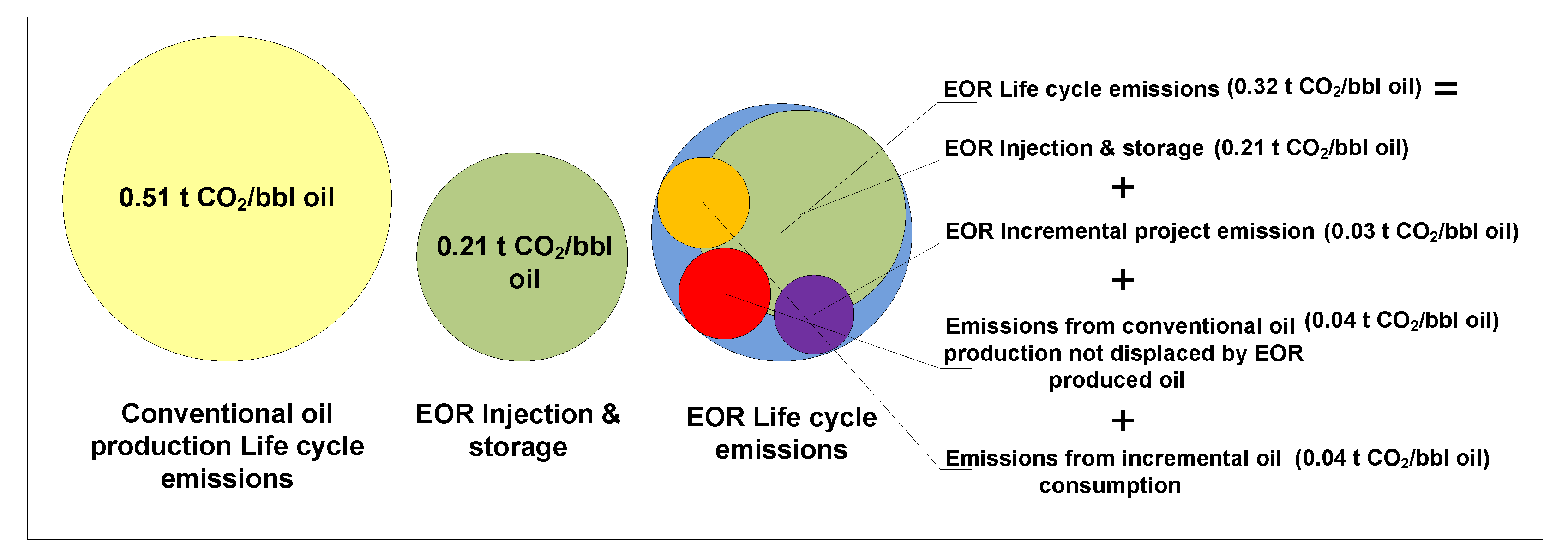
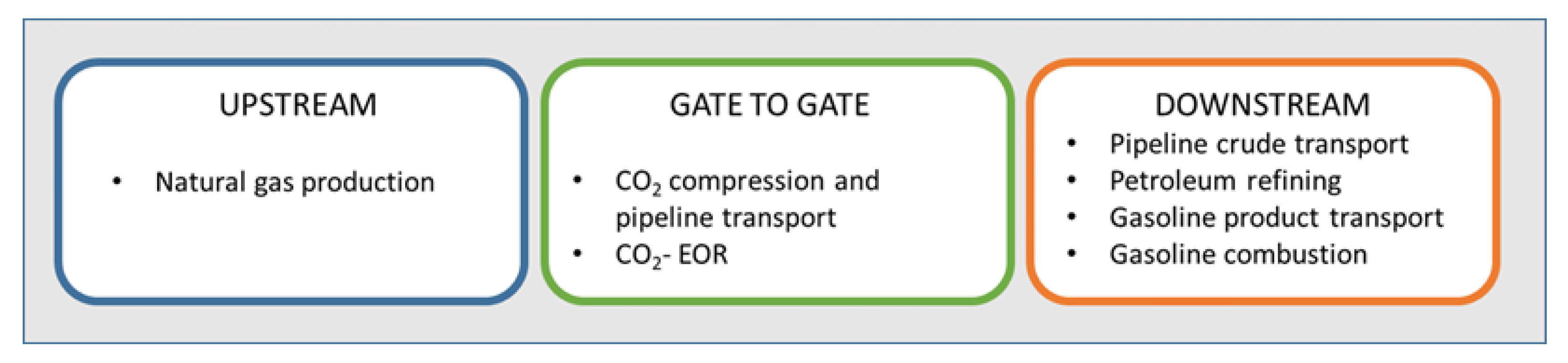
6. CO2-EOR Lifecycle Emissions
7. Discussion
8. Conclusions
Author Contributions
Funding
Institutional Review Board Statement
Informed Consent Statement
Data Availability Statement
Conflicts of Interest
References
- Fawzy, S.; Osman, A.I.; Doran, J.; Rooney, D.W. Strategies for mitigation of climate change: A review. Environ. Chem. Lett. 2020, 18, 2069–2094. [Google Scholar] [CrossRef]
- Gaurina-Međimurec, N.; Novak Mavar, K. Carbon Capture and Storage (CCS): Geological Sequestration of CO2. In CO2 Sequestration; Frazão, L.A., Ed.; IntechOpen: London, UK, 2019; pp. 1–21. [Google Scholar]
- IEA (International Energy Agency). Putting CO2 to Use. 2019. Available online: https://www.iea.org/topics/carbon-capture-and-storage/ (accessed on 5 January 2021).
- USEPA (United States Environmental Protection Agency). Inventory of U.S. Greenhouse Gas, Emissions and Sinks: 1990–2017. Available online: https://epa.gov/sites/production/files/2019-04/documents/us-ghg-inventory-2019-main-text.pdf (accessed on 5 January 2021).
- Martins, F.; Felgueiras, C.; Smitkova, M.; Caetano, N. Analysis of fossil fuel energy consumption and environmental impacts in European countries. Energies 2019, 12, 964. [Google Scholar] [CrossRef]
- Heuberger, C.F.; Staffell, I.; Shah, N.; Mac Dowell, N. What is the value of CCS in the future energy system? Energy Procedia 2017, 114, 7564–7757. [Google Scholar] [CrossRef]
- Budinis, S.; Krevor, S.; Mac Dowell, N.; Brandon, N.; Hawkes, A. An assessment of CCS costs, barriers and potential. Energy Strategy Rev. 2018, 22, 61–81. [Google Scholar] [CrossRef]
- Allinson, K.; Burt, D.; Campbell, L.; Constable, L.; Crombie, M.; Lee, A.; Lima, V.; Lloyd, T.; Solsbey, L. Best practice for transitioning from carbon dioxide (CO2) enhanced oil recovery EOR to CO2 storage. Energy Procedia 2017, 114, 6950–6956. [Google Scholar] [CrossRef]
- Husanović, E.; Novak, K.; Malvić, T.; Novak Zelenika, K.; Velić, J. Prospects for CO2 carbonation and storage in Upper Miocene sandstone of Sava Depression in Croatia. Geol. Q 2015, 59, 91–104. [Google Scholar] [CrossRef]
- Cuéllar-Franca, R.M.; Azapagic, F.A. Carbon capture, storage and utilisation technologies: A critical analysis and comparison of their life cycle environmental impacts. J. CO2 Util. 2015, 9, 82–102. [Google Scholar] [CrossRef]
- MIT (Technologies at the Massachusetts Institute of Technology). Available online: https://sequestration.mit.edu/tools/projects/ (accessed on 30 January 2021).
- Global CCS Institute. Available online: https://co2re.co/FacilityData (accessed on 30 January 2021).
- IEA (International Energy Agency). Available online: https://www.iea.org/fuels-and-technologies/carbon-capture-utilisation-and-storage (accessed on 30 January 2021).
- KAPSARC (King Abdullah Petroleum Studies and Research Center). Available online: https://datasource.kapsarc.org/explore/dataset/ (accessed on 30 January 2021).
- Hendriks, C.; Noothout, P.; Zakkour, P.; Cook, G. Implications of the reuse of captured CO2 for European climate action policies, Report to DG Climate Action. Ecofys and Carbon Count. 2013. Available online: http://www.scotproject.org/sites/default/files/Carbon%20Count,%20Ecofys%20%282013%29%20Implications%20of%20the%20reuse%20of%20captured%20CO2%20-%20report.pdf (accessed on 5 January 2021).
- IHS Markit. Chemical Economics Handbook—Carbon Dioxide. 2018. Available online: https://ihsmarkit.com/products/carbon-dioxide-chemical-economics-handbook.html (accessed on 5 January 2021).
- Olah, G.A. Beyond oil and gas: The methanol economy. Angew. Chem. Int. Ed. 2005, 44, 2636–2639. [Google Scholar] [CrossRef] [PubMed]
- Jiang, Z.; Xiao, T.; Kuznetsov, V.L.; Edwards, P.P. Turning carbon dioxide into fuel. Phil. Trans. R. Soc. A 2010, 368, 3343–3364. [Google Scholar] [CrossRef] [PubMed]
- Gnanamani, M.K.; Jacobs, G.; Pendyala, V.R.R.; Ma, W.; Davis, B.H. Chapter 4: Hydrogenation of carbon dioxide to liquid fuels. In Green Carbon Dioxide; Advances in CO2 Utilization; Centi, G., Perathoner, S., Eds.; John Wiley & Sons, Inc.: Hoboken, NJ, USA, 2014; pp. 99–115. [Google Scholar]
- Marlin, D.S.; Sarron, E.; Sigurbjörnsson, Ó. Process advantages of direct CO2 to methanol synthesis. Front. Chem. 2018, 6. [Google Scholar] [CrossRef] [PubMed]
- IEA (International Energy Agency). Exploring Clean Energy Pathways: The Role of CO2 Storage. 2019. Available online: https://www.iea.org/publications/reports/TheroleofCO2storage/ (accessed on 5 January 2021).
- Liu, H.J.; Were, P.; Li, Q.; Gou, Y.; Hou, Z. Worldwide status of CCUS technologies and their development and challenges in China. Geofluids 2017. [Google Scholar] [CrossRef]
- Mazzotti, M.; Pini, R.; Storti, G. Enhanced coalbed methane recovery. J. Supercrit. Fluids 2009, 47, 619–627. [Google Scholar] [CrossRef]
- Du, F.; Nojabaei, B. A review of gas injection in shale reservoirs: Enhanced oil/gas recovery approaches and greenhouse gas control. Energies 2019, 12, 2355. [Google Scholar] [CrossRef]
- Du, X.; Gu, M.; Liu, Z.; Zhao, Y.; Sun, F.; Wu, T. Enhanced shale gas recovery by the injections of CO2, N2, and CO2/N2 mixture gases. Energy Fuels 2019, 33, 5091–5101. [Google Scholar] [CrossRef]
- Novak Mavar, K.; Gaurina-Međimurec, N.; Hrnčević, L. Carbon Capture, Utilization and Storage (CCUS)—The Environmental Impact Rom Project Start to Closure. In Proceedings of the 7th International Symposium Mining and Environmental Protection, Vrdnik, Serbia, 25–28 September 2019; Ristović, I., Ed.; Faculty of Mining and Geology: Belgrade, Serbia, 2019; pp. 63–68. [Google Scholar]
- Wu, Y.; Li, P. The potential of coupled carbon storage and geothermal extraction in a CO2-enhanced geothermal system: A review. Geotherm. Energy 2020, 8, 19. [Google Scholar] [CrossRef]
- Harto, C.B.; Schroeder, J.N.; Horner, R.M.; Patton, T.L.; Durham, L.A.; Murphy, D.J.; Clark, C.E. Water Use in Enhanced Geothermal Systems (EGS): Geology of U.S. Stimulation Projects, Water Costs, and Alternative Water Source Policies; Argonne National Lab.(ANL): Argonne, IL, USA, 2014. [CrossRef]
- Brown, D.W. A Hot Dry Rock Geothermal Energy Concept Utilizing Supercritical CO2 Instead of Water. In Proceedings of the 25th Workshop on Geothermal Reservoir Engineering, Stanford, CA, USA, 24–26 January 2000; Stanford University: Stanford, CA, USA, 2000. [Google Scholar]
- Pan, F.; McPherson, B.J.; Kaszuba, J. Evaluation of CO2-fluid-rock interaction in enhanced geothermal systems: Field-scale geochemical simulations. Geofluids 2017. [Google Scholar] [CrossRef]
- Wang, C.L.; Cheng, W.L.; Nian, Y.L.; Yang, L.; Han, B.B.; Liu, M.H. Simulation of heat extraction from CO2-based enhanced geothermal systems considering CO2 sequestration. Energy 2018, 142, 157–167. [Google Scholar] [CrossRef]
- Olasolo, P.; Juárez, M.C.; Morales, M.P.; D’Amico, S.; Liarte, I.A. Enhanced geothermal systems (EGS): A review. Renew. Sustain. Energy Rev. 2016, 56, 133–144. [Google Scholar] [CrossRef]
- U.S. Department of Energy’s Office of Energy Efficiency and Renewable Energy. Enhanced Geothermal Systems Demonstration Projects. Available online: https://www.energy.gov/eere/geothermal/enhanced-geothermal-systems-demonstration-projects (accessed on 10 December 2020).
- Conboy, T.; Pasch, J.; Fleming, D. Control of a Supercritical CO2 Recompression Brayton Cycle Demonstration Loop. J. Eng. Gas. Turbines Power 2013, 135, 11. [Google Scholar] [CrossRef]
- Siddiqui, M.E.; Almitani, K.H. Energy analysis of the S-CO2 Brayton cycle with improved heat regeneration. Processes 2013, 7, 3. [Google Scholar] [CrossRef]
- Kaliyan, N.; Morey, R.; Wilcke, W.; Alagusundaram, K.; Gayathri, P. Applications of carbon dioxide in food and processing industries: Current status and future thrusts. In Proceedings of the ASABE Annual International Meeting, Conference Paper Number 076113, Minneapolis, MN, USA, 17–20 June 2007. [Google Scholar] [CrossRef]
- Global CCS Institute. Global Status of CCS. 2019. Available online: https://www.globalccsinstitute.com/resources/global-status-report/ (accessed on 10 December 2020).
- Tcvetkov, P.; Cherepovitsyn, A.; Fedoseev, S. The changing role of CO2 in the transition to a circular economy: Review of carbon sequestration projects. Sustainability 2019, 11, 5834. [Google Scholar] [CrossRef]
- IPIECA (International Petroleum Industry Environmental Conservation Association) & API (American Petroleum Institute). Oil and Natural Gas Industry Guidelines for Greenhouse Gas Reduction Projects, Part II: Carbon Capture and Geological Storage Emission Reduction Family. 2007. Available online: https://www.api.org/~/media/Files/EHS/climate-change/Carbon-Capture-Geological-Storage-Emission-Reduction-Family.pdf (accessed on 10 December 2020).
- Zevenhoven, R.; Kohlmann, J. Direct Dry Mineral Carbonation for CO2 Emissions Reduction in Finland. In Proceedings of the 27th International Technical Conference on Coal Utilization & Fuel Systems, Clearwater, FL, USA, 4–7 March 2002; pp. 743–754. [Google Scholar]
- Zevenhoven, R.; Kavaliauskaite, I. Mineral carbonation for long-term CO2 storage: An exergy analysis. Int. J. Appl. Thermodyn. 2004, 7, 23–31. [Google Scholar]
- IPCC (Intergovernmental Panel on Climate Changes). Special Report on Carbon Dioxide Capture and Storage. 2005. Available online: https://www.ipcc.ch/report/carbon-dioxide-capture-and-storage/ (accessed on 7 January 2021).
- Zevenhoven, R.; Teir, S.; Eloneva, S.; Aatos, S.; Sorjonen-Ward, P. CO2 Sequestration by Carbonation of Minerals and Industrial by-Products in Finland. In Proceedings of the R’07, Davos, Switzerland, 3–5 September 2007. [Google Scholar]
- Sipila, J.; Teir, S.; Zevenhoven, R. Carbon Dioxide Sequestration by Mineral Carbonation—Literature Review Update 2005–2007. Heat Engineering Lab. In Report VT 2008-1; Abo Akademi University: Espoo, Finland, 2008. [Google Scholar]
- Lu, J.; Wilkinson, M.; Haszeldine, R.S. Carbonate cements in Miller field of the UK North Sea: A natural analog for mineral trapping in CO2 geological storage. Environ. Earth Sci. 2011, 62, 507–517. [Google Scholar] [CrossRef]
- Bauer, S.; Class, H.; Ebert, M.; Gotze, H.; Holzheid, A.; Kolditz, O.; Rosenbaum, S.; Rabbel, W.; Schäfer, D.; Dahmke, A. Modelling, parameterization, and evaluation of monitoring methods for CO2 storage in deep saline formations the CO2 MoPa project. Environ. Earth Sci. 2012, 67, 351–367. [Google Scholar] [CrossRef]
- Novosel, D.; Leonard, N.; Mikulić, S.; Mudrić, D. Početni rezultati primjene utiskivanja ugljičnog dioksida za povećanje iscrpka nafte na proizvodnom polju Ivanić i Žutica (Initial results of CO2 injection for enhanced oil recovery from the Ivanić and Žutica Oil fields—In Croatian). Nafta i plin 2018, 38, 57–66. [Google Scholar]
- INA Group Annual Report. 2019. Available online: https://www.ina.hr/home/press-centar/publikacije/godisnja-izvjesca/ (accessed on 7 January 2021).
- Novosel, D. Pet godina utiskivanja CO2 za Povećanje Iscrpka Nafte na Polju Ivanić i Žutica—iskustva i rezultati (Five years of CO2 Injection for Enhanced oil Recovery from the Ivanić and Žutica fields—Experience and Results-In Croatian). Nafta i plin 2020, 40, 33–47. [Google Scholar]
- Novak Mavar, K. Modeliranje površinskoga transporta i geološki aspekti skladištenja ugljikova dioksida u neogenska pješčenjačka ležišta Sjeverne Hrvatske na primjeru polja Ivanić. (Surface Transportation Modelling and Geological Aspects of Carbon-Dioxide Storage into Northern Croatian Neogene Sandstone Reservoirs, Case Study Ivanić Field). Ph.D. Thesis, University of Zagreb, Zagreb, Croatia, 13 April 2015. [Google Scholar]
- Novak, K.; Zelenika, I. Carbon Capture and Storage Possibility, Case Study Ivanić Field. In Geomathematics—From Theory to Practice, Proceedings of the 6th Croatian-Hungarian and 17th Hungarian Geomathematical Congress, Opatija, Croatia, 21–23 May 2014; Cvetković, M., Novak Zelenika, K., Geiger, J., Eds.; Croatian Geological Society: Zagreb, Croatia, 2014; pp. 151–158. [Google Scholar]
- Interational Energy Agency (IEA). 2020. Available online: https://www.iea.org/commentaries/whatever-happened-to-enhanced-oil-recovery (accessed on 7 January 2021).
- Gaurina-Međimurec, N.; Novak Mavar, K.; Majić, M. Carbon Capture and Storage (CCS): Technology, projects and monitoring review. Geol. Min. Pet. Eng. Bull. 2018, 33, 1–15. [Google Scholar]
- Warwick, P.D.; Attanasi, E.D.; Blondes, M.S.; Brennan, S.T.; Buursink, M.L.; Doolan, C.A.; Freeman, P.A.; Jahediesfanjani, H.; Özgen Karacan, H.C.; Lohr, C.D.; et al. Carbon dioxide-enhanced oil recovery and residual oil zone studies at the U.S. Geological Survey. In Proceedings of the 14th International Conference on Greenhouse Gas Control Technologies, GHGT-14, Melbourne, Australia, 21–25 October 2018. [Google Scholar]
- Leung, D.Y.; Caramanna, G.; Maroto-Valer, M.M. An overview of current status of carbon dioxide capture and storage technologies. Renew. Sust. Energ. Rev. 2014, 39, 426–443. [Google Scholar] [CrossRef]
- Global CCS Institute. Introduction to industrial carbon capture and storage, Special Report. 2016. Available online: https://www.globalccsinstitute.com/wp-content/uploads/2019/08/Introduction-to-Industrial-CCS.pdf/ (accessed on 8 January 2021).
- National Energy Technology Laboratory (NETL). Air Products and Chemicals, Inc.: Demonstration of CO2 Capture and Sequestration of Steam Methane Reforming Process Gas used for Large Scale Hydrogen Production. 2017. Available online: https://www.netl.doe.gov/sites/default/files/netl-file/FE0002381.pdf (accessed on 9 January 2021).
- Preston, C. The CCS Project at Air Products’ Port. Arthur Hydrogen Production Facility; IEA Greenhouse Gas R&D Programme: Cheltenham, UK, 2018. [Google Scholar]
- U.S. Department of Energy (DOE) & National Energy Technology Laboratory (NETL). CO2-EOR Offshore Resource Assessment. 2014. Available online: https://netl.doe.gov/projects/files/FY14_CO2-EOROffshoreResourceAssessment_060114.pdf (accessed on 9 January 2021).
- Liu, H.; Consoli, C.; Zapantis, A. Overview of Carbon Capture and Storage (CCS) facilities globally. In Proceedings of the 14th Greenhouse Gas Control Technologies Conference (GHGT-14), Melbourne, Australia, 21–26 October 2018; 10pAvailable online: https://ssrn.com/abstract=3366353 or http://dx.doi.org/10.2139/ssrn.3366353 (accessed on 9 January 2021).
- Eide, L.I.; Batum, M.; Dixon, T.; Elamin, Z.; Graue, A.; Hagen, S.; Hovorka, S.; Nazarian, B.; Nøkleby, P.; Olsen, G.I.; et al. Enabling large-scale carboon capture, utilisation, and storage (CCUS) using offshore carbon dioxide (CO2) infrastructure developments—A review. Energies 2019, 12, 1945. [Google Scholar] [CrossRef]
- Madden, D.R. Case study: Kemper County IGCC project, USA. In Integrated Gasification Combined Cycle (IGCC) Technologies; Wang, T., Stiegel, G., Eds.; Woodhead Publishing: Sawston, UK, 2017; pp. 817–832. [Google Scholar]
- Paulson Institute. Financing Mega-Scale Energy Projects: A Case Study of the Petra Nova Carbon Capture Project. 2015. Available online: http://www.paulsoninstitute.org/wp-content/uploads/2015/10/CS-Petra-Nova-EN.pdf (accessed on 9 January 2021).
- Clean Air Task Force (CATF). Petra Nova: De-Risking Carbon Capture Business Models with Saline Storage. 2020. Available online: https://www.catf.us/2020/08/petra-nova-de-risking-carbon-capture-business-models-with-saline-storage/ (accessed on 9 January 2021).
- Hill, L.B.; Li, X.; Wei, N. CO2-EOR in China: A comparative review. Int. J. Greenh. Gas. Control. 2020, 103, 103173. [Google Scholar] [CrossRef]
- Cornot-Gandolphe, S. Carbon Capture, Storage and Utilization to the Rescue of Coal? Global Perspective with Focus on China and SAD; French Institute of International Relations IFRI: Paris, France, 2019. Available online: https://www.ifri.org/en/publications/etudes-de-lifri/carbon-capture-storage-and-utilization-rescue-coal-global-perspectives (accessed on 9 January 2021).
- Li, Q.; Ma, J.; Li, X.; Xu, L.; Niu, Z.; Lu, X. Integrated monitoring of China’s Yanchang CO2-EOR demonstration project in Ordos Basin. Energy Procedia 2018, 154, 112–117. [Google Scholar] [CrossRef]
- Dong, G.J.; Wang, Z.; Liu, H.; Ma, R.; Kong, D.; Wang, F.; Xin, X.; Li, L.; She, H. EOR survey in China-Part 1. In Proceedings of the SPE Improved Oil Recovery Conference, Society of Petroleum Engineers, Tulsa, OK, USA, 14–18 April 2018. [Google Scholar] [CrossRef]
- MIT. Carbon Capture and Sequestration Technologies. 2016. Available online: https://sequestration.mit.edu/tools/projects/jilin.html (accessed on 9 January 2021).
- National Energy Technology Laboratory (NETL). Summit Texas Clean Energy, LLC: Texas Clean Energy Project (TCEP). 2017. Available online: https://www.netl.doe.gov/sites/default/files/netl-file/FE0002650.pdf (accessed on 10 January 2021).
- U.S. Department of the Interior Bureau of Land Management. Draft Environmental Impact Statement for the Riley Ridge to Natrona Project. Volume 1, 2018. Available online: https://eplanning.blm.gov/public_projects/nepa/64342/138479/170483/01_Volume_I_of_II.pdf (accessed on 10 January 2021).
- Carruthers, K. Environmental Impact of CO2-EOR; Scottish Carbon Capture and Storage: Edingurgh, Scottland, 2014. [Google Scholar]
- Hrnčević, L. Analysis of the Impact of Implementation of the Kyoto Protocol on the Oil Industry and the Operations of the Oil Company (Analiza Utjecaja Provedbe Kyoto Protokola na Naftnu Industriju i Poslovanje Naftne Tvrtke-in Croatian). Ph.D. Thesis, University of Zagreb, Zagreb, Croatia, 2008. [Google Scholar]
- Dilmore, R. An Assessment of Gate-To-Gate Environmental Life Cycle Performance of Water-Alternating-gas CO2-Enhanced oil Recovery in the Permian Basin; Department of Energy (DOE)/National Energy Technology Laboratory (NETL): Pittsburgh, PA, USA, 2010.
- Department of Energy (DOE)/National Energy Technology Laboratory (NETL). Electricity Use of Enhanced oil Recovery with Carbon Dioxide (CO2-EOR); National Energy Technology Laboratory: Pittsburgh, PA, USA, 2009.
- Núñez-López, V.; Ramon, G.; Seyyed, H. Environmental and operational performance of CO2-EOR as a CCUS Technology: A Cranfield Example with Dynamic LCA Considerations. Energies 2019, 12, 448. [Google Scholar] [CrossRef]
- Finn, A.J.; O’Brien, J.V. Processing of Carbon Dioxide Rich Gas. In Proceedings of the GPA Conference, Madrid, Spain, 17–19 September 2014; Available online: https://www.costain.com/media/13020/gpa-conference-sept-2014-1mb.pdf (accessed on 10 January 2021).
- Faltison, J.; Gunter, B. Net CO2 Stored in North American EOR projects. Society of Petroleum Engineers. J. Can. Pet. Technol. 2010, 50, 7. [Google Scholar] [CrossRef]
- Hansen, H.; Eiken, O.; Aasum, T. Tracing the Path of CO2 from a Gas/Condensate Reservoir through an Amine Plant and Back into a Subsurface Aquifer-Case Study: The Sleipner Area, Norwegian North Sea. In Proceedings of the Offshore Europe oil and Gas Exhibition and Conference: Inform, Innovate, Inspire Conference, Aberdeen, UK, 6–9 September 2005. [Google Scholar] [CrossRef]
- Gaurina-Međimurec, N.; Pašić, B. CO2 underground storage and wellbore integrity. In Risk Analysis for Prevention of Hazardous Situations in Petroleum and Natural Gas Engineering; Matanović, D., Gaurina-Međimurec, N., Simon, K., Eds.; IGI Global: Hershey, PA, USA, 2013; pp. 169–217. [Google Scholar]
- Gaurina-Međimurec, N.; Novak Mavar, K. Depleted hydrocarbon reservoirs and CO2 injection wells—CO2 leakage assessment. Min. Geol. Pet. Eng. Bull. 2017, 32, 15–26. [Google Scholar] [CrossRef]
- Melzer, L.S. Carbon Dioxide Enhanced Oil Recovery (CO2 EOR): Factors Involved in Adding Carbon Capture, Utilization and Storage (CCUS) to Enhanced oil Recovery. Midland Texas: Melzer Consulting. National Enhanced Oil Recovery Initiative Resource. 2012. Available online: http://neori.org/Melzer_CO2EOR_CCUS_Feb2012.pdf (accessed on 10 January 2021).
- International Energy Agency (IEA). Can CO2-EOR Really Provide Carbon-Negative Oil? 2019. Available online: https://www.iea.org/commentaries/can-co2-eor-really-provide-carbon-negative-oil (accessed on 10 January 2021).
- Pehnt, M.; Henkel, J. Lifecycle assessment of carbon dioxide and storage from lignite power plant. Int. J. Greenh. Gas. Control 2009, 3, 49–66. [Google Scholar] [CrossRef]
- Marx, J.; Schreiber, A.; Zapp, P.; Haines, M.; Hake, J.-F.; Gale, J. Environmental evaluation of CCS using lifecycle assessment (LCA)—A synthesis report. Energy Procedia 2011, 4, 2448–2456. [Google Scholar] [CrossRef]
- Singh, B.; Stromman, A.H.; Hertwich, E.G. Environmental damage assessment of carbon capture and storage application of end point indicators. J. Ind. Ecol. 2012, 16, 407–419. [Google Scholar] [CrossRef]
- Turconi, R.; Boldrin, A.; Astrup, T. Lifecycle assessment of electricity generation technologies: Overview, comparably and limitations. Renevable Sustain. Energy Rev. 2013, 28, 555–565. [Google Scholar] [CrossRef]
- Singh, B.; Bouman, E.A.; Stromman, A.H.; Hertwich, E.G. Material use for electricity generation with carbon dioxide capture and storage: Extending life cycle analysis indices for material accounting. Res. Conserv. Recycle 2015, 100, 49–57. [Google Scholar] [CrossRef]
- Petrescu, I.; Cormos, C.C. Environmental assessment of IGCC power plants with pre-combustion CO2 capture by chemical and calcium looping methods. J. Clean. Prod. 2017, 158, 233–244. [Google Scholar] [CrossRef]
- Azzolina, N.A.; Hamling, J.A.; Peck, W.D.; Gorecki, C.D.; Nakles, D.V.; Melzer, L.S. A life cycle analysis of incremental oil produce via CO2 EOR. Energy Procedia 2017, 114, 6588–6596. [Google Scholar] [CrossRef]
- Cooney, G.; Littlefield, J.; Mariott, J.; Skone, T.J. Evaluatinng the climate benefits of CO2-enhanced oil recovery using life cycle analysis. Environ. Sci. Technol. 2015, 49, 7491–7500. [Google Scholar] [CrossRef] [PubMed]
- Clean Air Task Force (CATF). Net CO₂ Emission Reductions from Anthropogenic CO₂-EOR. 2019. Available online: https://www.catf.us/resource/co2-eor-emission-reduction/ (accessed on 10 January 2021).
- Thorne, R.J.; Sundseth, K.; Bouman, E.; Czarnowska, L.; Mathisen, A.; Skagestad, R.; Stanek, W.; Pacyna, J.M.; Pacyna, E.G. Technical and environmental viability of a European CO2 EOR system. Int. J. Greenh. Gas. Control. 2020, 92, 102857. [Google Scholar] [CrossRef]
- Sminchak, J.R.; Mawalkar, S.; Gupta, N. Large CO2 Storage volumes result in net negative emissions for greenhouse gas life cycle analysis based on records from 22 Years of CO2-Enhanced Oil Recovery operations. Energy Fuels 2020, 34, 3566–3577. [Google Scholar] [CrossRef]


| CO2 Source | Use of Captured CO2 | Application | Used CO2 (Mt/y) | Share (%) |
|---|---|---|---|---|
| Fossil fuels Biomass Underground deposits Industrial processes Air | Direct use | EOR, EGR, ECBM | 78 | 34 |
| Food and beverages | 14 | 6 | ||
| Heat transfer fluids (EGS, supercritical CO2 power cycle) | - | - | ||
| Conversion | Yield-boosting (urea/fertilizers) | 131 | 57 | |
| Chemicals (intermediates, polymers, formic acid) | 7 | 3 | ||
| Fuels (methane, renewable methanol, gasoline/diesel/aviation fuel) | ||||
| Building materials (aggregates, cement, concrete) |
| Project Name | CO2 Capture Capacity (Mt/y) | Stage | Location | Industry | |
|---|---|---|---|---|---|
| 1. | Petrobras Lula Oil Field CCS Project | 0.7 | Operate | Brazil | Natural gas processing |
| 2. | Alberta Carbon Trunk Line (“ACTL”) with Agrium CO2 Stream | 0.6 | Execute | Canada | Fertilizer production |
| 3. | Alberta Carbon Trunk Line (“ACTL”) with North West Sturgeon Refinery CO2 Stream | 1.4 | Execute | Oil refining | |
| 4. | Boundary Dam Carbon Capture and Storage Project | 1 | Operate | Power generation | |
| 5. | Great Plains Synfuel Plant and Weyburn-Midale Project | 3 | Operate | Synthetic natural gas | |
| 6. | PetroChina Jilin Oil Field EOR Project (Phase 2) | 0.5 | Define | China | Natural gas processing |
| 7. | Sinopec Qilu Petrochemical CCS Project | 0.5 | Define | Chemical production | |
| 8. | Yanchang Integrated Carbon Capture and Storage Demonstration Project | 0.4 | Define | ||
| 9. | Sinopec Shengli Power Plant CCS Project | 1 | Define | Power generation | |
| 10. | Huaneng GreenGen IGCC Project (Phase 3) | 2 | Evaluate | ||
| 11. | Uthmaniyah CO2-EOR Demonstration Project | 0.8 | Operate | Saudi Arabia | Natural gas processing |
| 12. | Abu Dhabi CCS Project (Phase 1 being Emirates Steel Industries (ESI) CCS Project) | 0.8 | Execute | United Arab Emirates | iron and steel production |
| 13. | Texas Clean Energy Project | 2.4 | Define | United States | Power generation |
| 14. | Kemper County Energy Facility | 3 | Execute | ||
| 15. | Petra Nova Carbon Capture Project | 1.4 | Execute | ||
| 16. | Air Products Steam Methane Reformer EOR Project | 1 | Operate | Hydrogen production | |
| 17. | Coffeyville Gasification Plant | 1 | Operate | Fertilizer production | |
| 18. | Enid Fertilizer CO2-EOR Project | 0.7 | Operate | ||
| 19. | Lost Cabin Gas Plant | 0.9 | Operate | Natural gas processing | |
| 20. | Shute Creek Gas Processing Facility | 7 | Operate | ||
| 21. | Val Verde Natural Gas Plants | 1.3 | Operate | ||
| 22. | Riley Ridge Gas Plant | 2.5 | Evaluate | ||
| 23. | Century Plant | 8.4 | Operate | ||
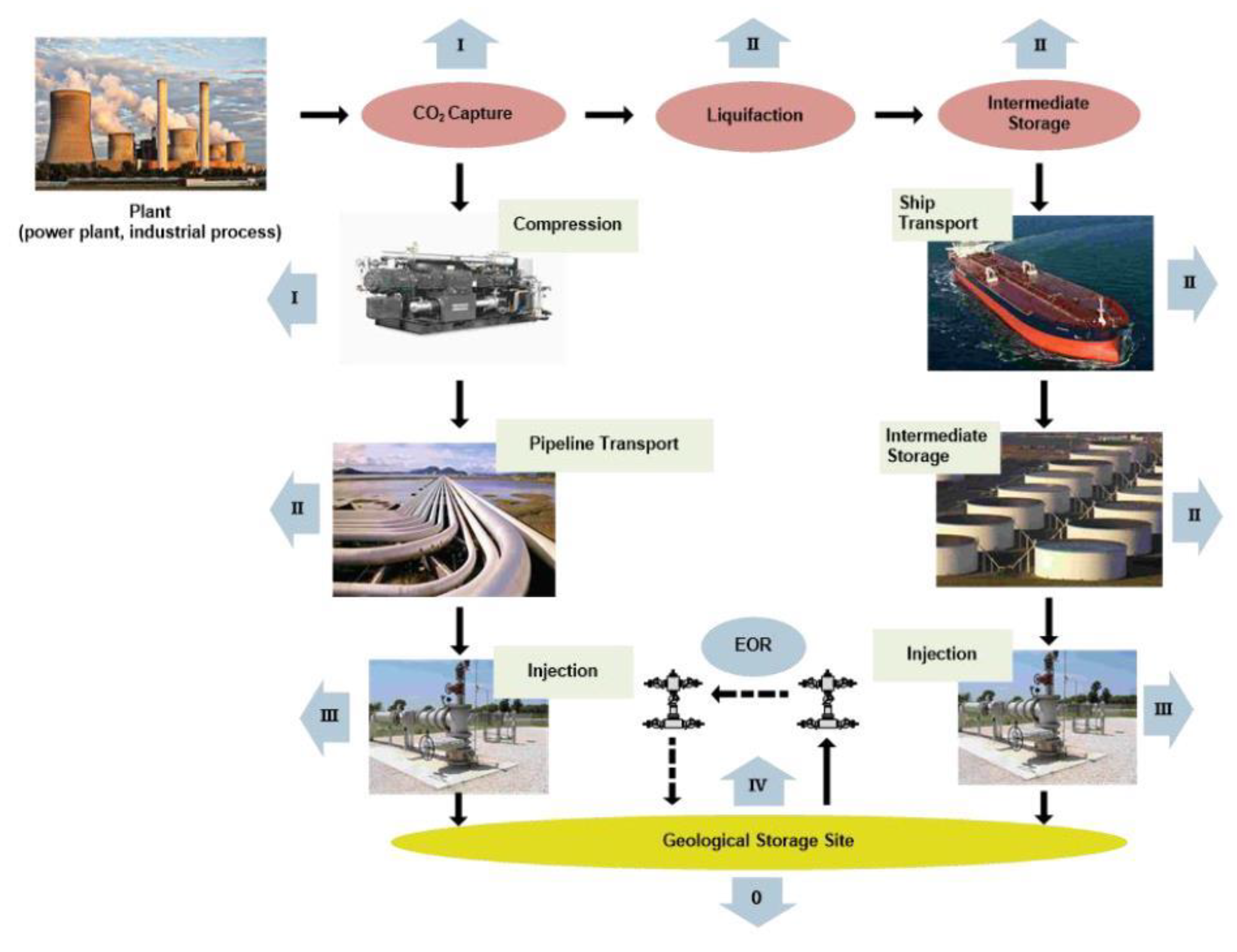
| Activity | Emission Source | Emission Type | Direct/Indirect Emissions | GHG Type |
|---|---|---|---|---|
| 0. CCS/CO2-EOR site evaluation and construction | Fuel combustion associated with site evaluation and construction | Combustion | Direct | CO2, CH4, N2O |
| Purchased electricity associated with site evaluation and construction | Indirect | Indirect | CO2, CH4, N2O | |
| I. CO2 capture | Gas treatment equipment | Combustion, vented and fugitive | Direct | CO2, CH4, N2O |
| Uncaptured CO2 and CH4 | Vented and fugitive | Direct | CO2, CH4 | |
| Purchased electricity associated with CO2 capture processes | Indirect | Indirect | CO2, CH4, N2O | |
| Processing and disposal of CO2 extraction agent | Combustion and fugitive | Direct | CO2, CH4, N2O | |
| II. CO2 transport | Compressors | Combustion and fugitive | Direct | CO2, CH4, N2O |
| Mobile combustion sources | Combustion | Direct | CO2, CH4, N2O | |
| Pressurized equipment and pipeline leakage | Fugitive | Direct | CO2 | |
| Maintenance or emergency releases | Vented | Direct | CO2, CH4 | |
| Intermediate storage | Vented | Direct | CO2 | |
| Loading/unloading | Fugitive | Direct | CO2 | |
| Purchased electricity associated with transport activities | Indirect | Indirect | CO2, CH4, N2O | |
| III. Injection | Compressors | Combustion and fugitive | Direct | CO2, CH4, N2O |
| Pressurized CO2 injection equipment | Fugitive | Direct | CO2 | |
| Maintenance or emergency releases | Vented | Direct | CO2, CH4 | |
| Purchased electricity associated with injection activities | Indirect | Indirect | CO2, CH4, N2O | |
| Production wells | Vented, combustion and fugitive | Direct | CO2, CH4, N2O | |
| Recycled gas treatment equipment | Combustion, vented and fugitive | Direct | CO2, CH4, N2O | |
| IV. CO2 storage (geological formation) | Physical leakage from a geological formation | Fugitive | Direct | CO2, CH4 |
| CO2 leakage from wells | Vented and fugitive | Direct | CO2, CH4 | |
| Uncaptured CO2 coproduced with hydrocarbons | Vented and fugitive | Direct | CO2, CH4 |
 CO2-EOR specificity.
Publisher’s Note: MDPI stays neutral with regard to jurisdictional claims in published maps and institutional affiliations. |
© 2021 by the authors. Licensee MDPI, Basel, Switzerland. This article is an open access article distributed under the terms and conditions of the Creative Commons Attribution (CC BY) license (http://creativecommons.org/licenses/by/4.0/).
Share and Cite
Novak Mavar, K.; Gaurina-Međimurec, N.; Hrnčević, L. Significance of Enhanced Oil Recovery in Carbon Dioxide Emission Reduction. Sustainability 2021, 13, 1800. https://doi.org/10.3390/su13041800
Novak Mavar K, Gaurina-Međimurec N, Hrnčević L. Significance of Enhanced Oil Recovery in Carbon Dioxide Emission Reduction. Sustainability. 2021; 13(4):1800. https://doi.org/10.3390/su13041800
Chicago/Turabian StyleNovak Mavar, Karolina, Nediljka Gaurina-Međimurec, and Lidia Hrnčević. 2021. "Significance of Enhanced Oil Recovery in Carbon Dioxide Emission Reduction" Sustainability 13, no. 4: 1800. https://doi.org/10.3390/su13041800
APA StyleNovak Mavar, K., Gaurina-Međimurec, N., & Hrnčević, L. (2021). Significance of Enhanced Oil Recovery in Carbon Dioxide Emission Reduction. Sustainability, 13(4), 1800. https://doi.org/10.3390/su13041800