Abstract
Today, the attention in the retrofitting of building is quickly growing. In this field, the re-use of waste materials and the innovation in the retrofitting techniques are among the crucial topics. Generally, thermal capacity and seismic resistance are two aspects very felt by the building owners. Commonly, independent approaches are assessed in order to cover the energy and mechanical lacks of a building. In such a way, the intervention may result time- and cost-consuming or, sometimes, poorly effective. The present paper aimed to propose and validate a new retrofitting system based on the partial use of waste materials, such as fly ash and expanded glass (acting as a matrix), and a fiber open grid reinforcement. The proposal is suitable for the plastering of building with the double scope of thermal insulation and seismic strengthening throughout a unique application. An experimental investigation was carried out considering small-scaled masonry panels with double-side retrofitting. The studied parameters were thermal transmittance and shear strength. The results evidenced the effectiveness of the proposed technique, able to significantly improve the un-retrofitted masonry, from both the thermal and mechanical point of view.
1. Introduction
Masonry heritage includes a huge number of different structures in terms of dimensions, morphology, materials, textures, etc., which are vulnerable against to the in-plane and out-of-plane load, especially in seismic prone-zones (see Figure 1). The field of civil engineering is now more and more oriented to the preservation, consolidation, and strengthening of existing buildings with respect to the design of a new ones. At the same time, the research is fast growing when focusing on the development of novel strengthening systems. At early as the 1990s, the use of composites, known as Fiber Reinforced Polymer or Fiber Reinforced Plastic (FRP), emerged as a valuable structural material for buildings and infrastructures. FRP composites consist in an epoxy-based matrix and a non-metallic fibrous reinforcement (generally carbon). The low viscosity of the epoxy-based resin allows the impregnation of the fiber sheet making the two different materials working in a two-phase composite. In fact, the matrix protects the fibers from environmental actions and mechanical damage and, at the same time, allows the stresses transfer between fibers through adhesion. While the fibers guarantee relevant strength and stiffness in the reinforcement direction, self-weight of the composite is negligible. Due to these characteristics, FRPs were largely used in strengthening of structural members, such as column, floor, wall, beam, arch, vault, or even the entire building [1,2,3,4,5,6,7,8], as External Bonded Reinforcement (EBR), where the polymeric resin is also responsible of the adhesion between the composite and the existing substrate.
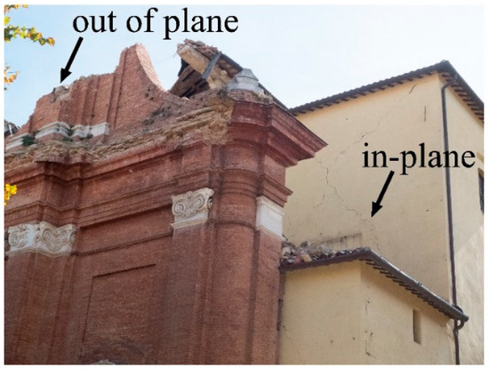
Figure 1.
Example of seismic damages in a masonry church: out of plane collapse of the tympanum and in-plane X-shaped crack.
Over the decades, the FRP demonstrated their drawbacks or rather the impossibility of applying on wet substrate, the poor fire resistance, and the low reversibility. The latter is a crucial issue in the case of cultural masonry building heritage. Even if different fibers were experienced in the past for FRP (i.e., glass, basalt, aramid, carbon, etc.), the responsibility of the mentioned disadvantages is mainly related to the epoxy-based matrix properties.
For this reason, more recently, a new type of composites was considered for the structural retrofitting: Fabric Reinforced Cementitious Mortar (FRCM) [9,10,11,12,13,14,15,16,17,18,19,20,21]. The main idea consists of substituting the resin with an inorganic-like matrix. In fact, a mortar (lime- or cement-based) is more compatible with masonry substrates. On the other hand, mortar cannot properly impregnate the fiber-sheet because the relevant viscosity. Thus, open grid was used (i.e., a fabric); in such a way, the mortar passes through the voids and promote the composite action. The first challenge when dealing with FRCM was computing the tensile characteristic behavior. Different test methods and types of specimen preparation were conveyed in many laboratories in order to define a standard. The gripping method is now recognized in European countries. Available technical codes (e.g., Technical Document by the Italian National Research Council - CNR DT 215 [22]) consider the tensile stress-strain law to be tri-linear, where the third branch assumes a slope almost equal to the elastic modulus of the dry fabric in tension. Nonetheless, the scientific literature reports on a significant number of tests where FRCMs exhibit a bi-linear approximation, depending on the level of matrix’s damage.
The main differences concerning the FRP versus FRCM tensile behavior is the matrix/fabric interface bond strength, which is significantly higher in the case of impregnation with epoxy-based resin (see Figure 2a), allowing the contemporary fibers breakage of the whole composite under tensile, while a slippage of the fiber from the matrix is mainly observed in case of inorganic mortar (see Figure 2b) causing the premature crisis of part of the yarns and the fiber fraying. Evident in Figure 2 is the similar length of the fiber yards when analyzing the FRP coupon after a tensile test, and the relevant different length of the fiber yards, or even of fibers in the same yard, in the case of FRCM.
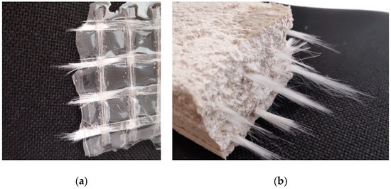
Figure 2.
Detail of the fiber failure due to direct tensile test: (a) Fiber Reinforced Plastic (FRP) and (b) Fabric Reinforced Cementitious Mortar (FRCM) with the same fabric.
Although the literature concerning the FRCMs is now relatively conspicuous (about 600 papers according to the Scopus database [23]), the potential use for energy improvement of existing buildings is currently a not considered option. Inorganic matrix is essentially a plaster for existing building; thus, it can be insulating oriented when a significant thickness of a sufficiently low thermal conductivity mortar is provided. From this perspective, a new material was recently developed by combining fly ash, metakaolin, and expanded glass aggregate [24]. The result was a geopolymer-based mortar with valuable mechanical and thermal properties. Furthermore, a new inorganic-based composite was also developed by combining a glass fabric with the innovative mortar, making a Fabric Reinforced Geopolymer Mortar (FRGM), as reported in Reference [25]. The FRGM was found to have comparable tensile strength and global tensile stress-strain behavior with respect a traditional FRCM when the same fabric was considered. On the other hand, the insulating capacity was significantly enhanced, evidencing the suitability of the FRGM for energy retrofitting contrarily to the FRCM that is commonly not insulating. Numerical and theoretical simulations were both provided in Reference [25] in order to demonstrate the effectiveness of the new system in case of masonry wall application. The results confirmed the double benefit of the FRGM installation in terms of shear strength and thermal transmittance.
Based on these encouraging outcomes, the present research aimed to further validate the effectiveness of the proposed geopolymer-based composites applied on masonry panels by experimental investigations. At this scope, clay brick masonry panels were constructed and reinforced; thus, thermal conductivity test and diagonal compressive test were carried out. The goal was to compare the performances of a FRCM (lime-based matrix) with respect to the FRGM from Reference [25] by considering same reinforcing fabric (glass mesh) and identical geometrical dimensions (i.e., thickness of the plaster, brick, mortar joints, and masonry texture).
2. Background Summary
Although the study of the in-plane capacity of masonry reinforcement with Inorganic Matrix Composite (IMC) systems, such as FRCM and Composite Reinforced Mortar (CRM), boasts a large number of current works [26], the research on seismic and energy efficiency is very limited [27]. Commonly, diagonal compression tests are performed to compare the in-plane behavior of unreinforced masonry (URM) with the strengthened one. For example, a Glass-FRP reinforced mortar coating was used for retrofitting panels of different masonry types and thickness. Furthermore, different mortars were considered for the coating. Significant increasing both in shear strength and ductility were found in References [28,29]. An analytical predictive model was also calibrated by the authors based on their own data. The formulation highlighted that the contribution of the CRM-retrofitting was influenced by the characteristics of both the masonry and the reinforcement. Similar conclusions were delivered in Reference [9] throughout an “artificial neural networks”-based method elaboration of existing data.
Shear tests were carried out on masonry panels made of solid bricks and retrofitted with GFRP [30]. In particular, the glass fiber grid was inserted within a thermal insulating plaster. The latter was made of a low-strength lime-based mortar having a compressive capacity lower than 1 MPa. The thermal resistance of the mortar was evaluated by means of the thermal flux meter methodology consisting in the measurement of the heat flux through the sample and the surface temperatures in the cold and hot sides of the specimen. The thermal conductivity of the coating was estimated about 0.1 W/mK. The results evidenced that the adhesion between the masonry and the lime-based matrix was the weakness of the strengthening. A significant shear strength increase was met only in case of higher compressive strength of the mortar-matrix. In other words, when the thermal conductivity of the retrofitted masonry is significantly decreased with respect to the un-retrofitted one, the shear strength gain is negligible. This result was also confirmed in Reference [31].
In 2016, Micelli et al. investigated the shear behavior of full-scaled masonry panels reinforced with hydraulic mortar and glass fiber grid by means of shear-diagonal test set up [32]. The study covered also the case of multi-leaf wall. The application of the FRCM/CRM reinforcement was responsible for the increasing of the load capacity both in the cases of single or double leaf panels, due to the significant variation of the failure mode, passing from the localized sliding of the joints in case of URMs to the diffuse cracking of the FRCM-strengthened specimens. The FRCM-retrofitting was studied in double side and single side application in Reference [33]. The specimens jacketed on only one side exhibited the worst behavior in terms of load capacity, due to the out-of-plane deformation. Again, the shear behavior of the URM was modified by the FRCM in a more ductile trend due to the progressive a wider diffusion of numerous cracks. Similar conclusions are reported in Reference [34], where the used FRCM-system changed the failure mode of the panels from joint-sliding to diagonal cracking corresponding to larger strength and ductility. Moreover, the initial stiffness was found 39% larger with respect to the un-strengthened masonry when double side application of FRCM was provided.
A shear strength gain of about 78% and 23% for FRCM strengthened solid clay-brick and hollow clay-block triplets, respectively, was recorded in Reference [35]. During diagonal compression tests, the observed failure occurred through the mortar joints and bricks, and any debonding of the strengthening layer or tearing of the fiber bundles was observed. Moreover, a single-sided strengthening was also considered above an external thermal insulation layer, with the aim of evaluating its possible application on buildings with previous thermal improvement. In presence of external thermal insulation layer, the in-plane capacity was similar to that recorded for strengthened walls thank to the additional installation of transversal connectors. In 2019, an experimental investigation demonstrated that the maximum in-plane load, the shear stiffness, and the shear ductility are all improved if FRCM-strengthening is used for masonry panels retrofitting [36]. These increments were not proportional to the reinforcement ratio. The failure mode in the case of URM was the sliding along the interface between bricks and mortar, while, in the case of FRCM-strengthened panels, the mode of failure was the diagonal cracking.
An attempt to assess a combined system for seismic and energy retrofitting was performed in Reference [37]. The proposed solution consisted of a FRCM-like system, also named Textile Reinforced Mortar (TRM), with capillarity tubes embedded into a mortar layer or a FRCM combined with thermal insulation panels. The efficiency of the combined solution was demonstrated for a reinforced concrete building case study, reporting a reduction of intervention’s payback from 50 to 10 years. The same combined solution was investigated on simulating buildings [27,38] in order to determine the payback periods for types and different scenarios (i.e., zones with different seismic risk and climate condition). In general, the adoption of a combined solution leads to a dramatic reduction of the payback period. In fact, the results demonstrate that, the integrated approach is cost-saving (up to 25%) with respect to the upgrading of a building only seismically or in terms of energy.
3. Materials and Methods
This section describes in brief the materials properties and the test set up. Thermal measurements were firstly carried out, since the kind of test adopted is non-destructive, while the mechanical tests were later conducted on the same specimens.
3.1. Mechanical Experimental Test
The test layout is reported in Table 1. In particular, the label of the specimen, the type of masonry and the used strengthening systems are detailed. The label URM refers to Un-Reinforced Masonry, which is the control specimen. A strengthening system made up of 3 cm thick mortar was considered, involving Natural Hydraulic Lime (NHL) mortar or GeoPolymer Mortar (GPM) according to Reference [25]. The same mortars were used as matrices for FRCM systems, namely FRCM or FRGM, with a nominal thickness equal to 1.5 cm per side. In every case, the strengthening was applied on both sides of the masonry panel. Two specimens per series were tested according to the end-number in the label.

Table 1.
Experimental specimens’ layout.
The experimental program involved masonry panels (510 mm × 510 mm × 120 mm) made up of clay brick (250 mm × 120 mm × 55 mm) and lime-based mortar joints (10 mm thickness). The compression strength of the masonry was equal to 8.70 ± 9% MPa, while the clay brick had a 24.06 ± 14% MPa compression strength and the mortar for the joints had a 6.12 ± 5% MPa compression strength (see References [39,40,41]). The strengthening FRCM-system consisted of a lime-based mortar and a dry AR (Alkali Resistant) glass fiber mesh. The dimension of the mesh was 12 × 12 mm, with a 60 mm2/m equivalent thickness in the two orthogonal directions and a fiber density of 300 g/m2. The tensile strength, the elastic modulus and the maximum elongation of the textile were experimentally evaluated and resulted equal to 1929 ± 14% MPa, 108 ± 16% GPa and 0.018 ± 12%, respectively [42]. The FRCM matrix (namely NHL) had a 9.1 ± 3% MPa compressive strength after 28-day curing at environmental conditions (22–24 °C and ~50% relative humidity), while the FRGM geo-matrix (namely GPM) had a 5.93 ± 5% MPa compressive strength after 28-day curing at the same environmental conditions. The FRCM and FRGM were characterized in Reference [25], and the results are further reported in Table 2 in terms of tensile strength (σu), ultimate strain (εu), un-cracked slope (EI), and cracked slope (EII).
Table 2.
Tensile strength, maximum strain, and elastic moduli of FRCM and Fabric Reinforced Geopolymer Mortar (FRGM) [25].
The diagonal tension (shear) tests were conducted by load control throughout a pump connected to a hydraulic jack. The whole test setup (according to [43]) is illustrated in Figure 3. Steel shoes were utilized for applying the load along the diagonal of the panel. The contact length between the steel shoe and the masonry panel edge was 100 mm. A 30-ton load cell was adopted for the load recordings, while the specimens was equipped with two Linear Variables Displacements Transducers (LVDTs), located one per sides (A and B, according to Figure 3) and oriented in the vertical and the horizontal ways.
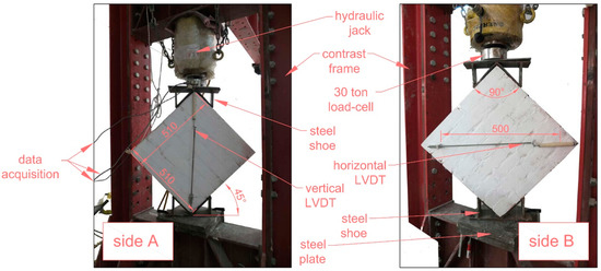
Figure 3.
Diagonal shear test setup (dimensions in mm) [43].
A 30-mm thick steel plate was placed at the bottom of the sample (under the steel shoe) in order to put-in-contrast the sample itself with the steel rigid frame and the hydraulic jack. The LVDTs were attached to the sample by means of epoxy-based putty and put in contact with a rigid steel bar (fixed to the masonry at the opposite extremity) in order to obtain a 500 mm measuring length. In addition, two cameras were located (one per side) in front of the sample for video recording the crack pattern evolution and catch the dominant failure mode. The data acquisition was obtained by electronically connecting the load cell and the two LVDTs to a control panel with a computer for the elaboration.
3.2. Thermal Experimental Test
The thermal performance of the specimens was evaluated by means of the experimental setup reported in Figure 4. A side of the wall (hot side) was continuously heated by four 250 W halogen lamps to ensure steady state conditions (Figure 4a), while the other side (cold side) was kept without any thermal load (Figure 4a). The halogen lamps were placed at the same positions for all the tests, according to the dimensions in Figure 4b,c. Furthermore, a mono-dimensional heat flux was guaranteed by placing an insulating ring around each wall (Figure 4b). All the samples were initially painted with the same color (white) in order to homogenize the reflectance of radiation from external surfaces [44]. On the other hand, also in practical application, a finishing painted layer is usually applied on mortar.
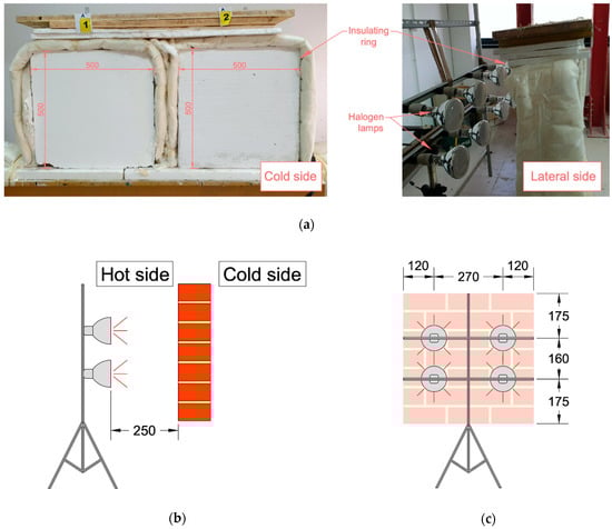
Figure 4.
Thermal test setup: (a) front and lateral views, (b) schematic lateral view, and (c) schematic front view (dimensions in mm).
The surface temperature of both sides was monitored over the time by means of type K thermocouples until the hot side of the wall reached a constant value. Moreover, the temperatures distribution on the entire surface of the samples was checked through a thermal camera (e.g., in Figure 5). The environmental temperature was determined using a thermo-hygrometer placed around one meter far from the cold side, and it will be referred as Tout in the following. The emissivity of the surface of the specimens was measured involving a thermo-camera and placing a black adhesive tape of known emissivity on the surface itself [45]. The measurements were performed in an indoor laboratory; therefore, the local wind velocity measured with the hot wire anemometer and in close proximity of the wall was zero or even negligible. Hence, the convective heat transfer coefficient (hc), which depends directly on the air velocity in proximity of the wall, will be assumed equal to zero in the transmittance computation [46].
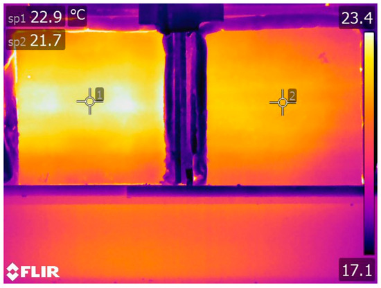
Figure 5.
Infrared thermography of a couple of specimens.
The thermal transmittance U was computed in relation to the experimental set up, according to Reference [47], as stated in Equations (1)–(2). The so-computed experimental results cannot be considered as the precise transmittance values, in absolute terms. Nonetheless, the aim of the investigation was to compare the relative thermal characteristic of the specimens; therefore, the performed measures can be considered effective for that scope.
- R′ is the thermal resistance of the wall;
- Rint is the contribution of internal convective resistance (0.13 m2 K W−1);
- Rext is the contribution of external convective resistance (0.04 m2 K W−1);
- Twh is the surface temperature referred to the hot side of the wall;
- Twc is the surface temperature referred to the cold side of the wall;
- εtot is the emissivity of the wall, assumed equal to 0.93;
- Tout is the environmental temperature, as previous discussed;
- hc is the convective heat transfer coefficient, here assumed equal to zero, as previous discussed; and
- U is the thermal transmittance of the wall.
4. Results
The experimental outcomes in terms of energy and mechanical performances of the URM and retrofitted specimens are reported in the present section. The aim is to compare the thermal and shear capacities with respect to the reference specimens in order to evaluate the effectiveness of the strengthening and, at the same time, investigate the thermal effectiveness of the proposed innovative system. In particular, the mechanical subsection reports results referred to the shear strength, stiffness and ductility, while the thermal section concerns the insulation capacity.
4.1. Mechanical
The shear stress-strain law of the URM manifests a first linear or quasi linear branch up to the peak (i.e., shear strength). After, the masonry suddenly fails due to the sliding along the joints (typically in the horizontal joint or in a step-stairs configuration). As a consequence, the post peak branch is almost negligible, involving a very low ductility (see Figure 6).
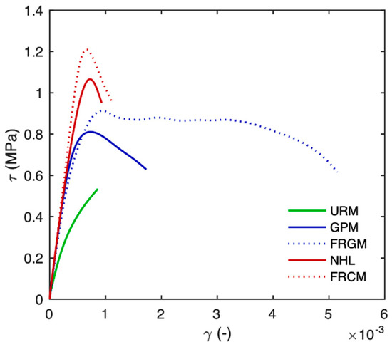
Figure 6.
Experimental shear stress-strain curves (averaged from two specimens per series).
In case of FRCM-strengthened masonry, the first elastic branch may be slightly stiffer depending on the properties of the FRCM-matrix and its thickness, while the shear strength is higher in all cases. A relevant difference with respect to the URMs is obtained analyzing the post-peak branch, where a significant residual strength is registered, as well as a higher deformability (again, Figure 6). This ductile behavior is mainly due to the presence of fabric within the FRCM that allows a drastic change of the kind of failure. In fact, in case of strengthened panels, the cracking phenomenon evolves up to the crisis and diffuse cracks are recorded, parallel to the load direction [9]. The slope of the post-peak branch may be more or less pronounced depending on the properties of the reinforcement system. In fact, at the damage stage, the matrix exhibited a larger number of micro-cracks for the GPM and FRGM series with respect to the NHL and FRCM ones; with consequent larger deformations (see Figure 6).
In the case of a post-peak plateau, the ultimate shear strain (γu) was assumed as corresponding to the load failure of the specimens, while, in case of dramatic softening, the ultimate shear strain was herein assumed equal to the strain corresponding to a fixed stress level: the 80% of the shear strength. In general, the shear strain (γ) was calculated as the sum of the vertical and the horizontal deformations in absolute value (according to measures of the vertical and the horizontal LVDT in Figure 3), as reported in Equation (3) [43]. The shear strength (τmax) was computed in all cases as the of the maximum load (Pmax) divided by the net cross-section of the masonry (An = 510 × 120 mm2), as reported in Equation (4) [43]. The ductility (µ) was calculated equal to the percentage scatter between the ultimate strain () and the strain corresponding to the shear strength (), according to Equation (5). Lastly, the shear elastic modulus (G) was herein assumed equal to the slope of the secant crossing the two points corresponding to the 5% and the 40% of the shear strength, as shown in Equation (6). The mechanical outcomes are all reported in Table 2, while the shear stress-strain relationships are illustrated in Figure 6 for all the samples. Since the test has been performed in load control, the slope of the post-peak branch may be more inaccurate with respect to the initial one.
In addition, the failure mode was classified in Table 3, on the basis of accurate observations of the videos. The observed failures are listed in the following:
Table 3.
Shear test results.
- HS—horizontal sliding along a bed joint (see Figure 7a);
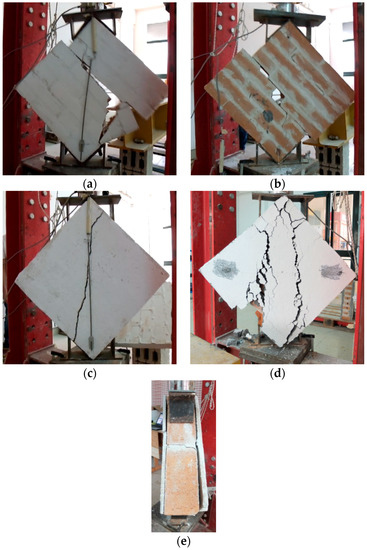 Figure 7. Examples of the failure mode: (a) horizontal sliding, (b) step-stairs sliding, (c) diagonal crack, (d) multi crack, and (e) detachment (lateral view).
 - SS—step-stairs sliding along both vertical and horizontal joints (see Figure 7b);
- DC—diagonal crack involving both the brick and the mortar (see Figure 7c);
- MC—multi crack with pseudo quasi parallel development (see Figure 7d); and
- D—detachment of the plaster (see Figure 7e).
The URM panels failed due to the loss of bond between the mortar and the brick; the shear strength and the ductility are both very modest when compared to those of the retrofitted specimens. Three general considerations can be pointed out for the reinforced specimens.
- The initial elastic shear stiffness is mainly affected by the properties of the IMC-matrix. NHL and GPM panels manifested almost doubled stiffness when compared with URM ones.
- The shear strength is manly affected by the properties of the IMC-fabric. In fact, for FRCM and FRGM panels, a more relevant shear strength gain was obtained if compared with NHL and GPM, respectively.
- The shear ductility is manly affected by the properties of the IMC-system. The use of GPM-based reinforcement demonstrated a larger shear strain capacity with respect to the NHL-based ones, because micro-cracks opened within the entire reinforced surface.
A further consideration concerning the matrix effect can be pointed out: in absence of fabric, both the NHL and GPM matrices produced a significant gain of the masonry shear strength. In particular, the presence of NHL-layers basically doubled the shear capacity, while the increment of ductility is quite moderate. Contrarily, the GPM specimens manifested a shear capacity incremented of about 50%, while the ductility was increased of 130%. From the ductility point of view, the use of GPM clearly involved larger shear deformations, related to the different failure modes in all cases. In fact, all the NHL-based specimens exhibited the detachment of the retrofitting independently from the presence of the fabric within (also according to Reference [30]). The elastic shear modulus was found influenced by both the stiffness and the thickness of the IMC-matrix. Moreover, the fabric effect provided a further strength increment. In fact, the application of the FRCM led to a 129% gain of shear capacity and 74.5% increment of ductility. Even with the presence of fabric, the geopolymer-based system exhibited a lower capacity gain (72%) but a higher increment of ductility (516%). It can be asserted that the innovative GPM–based system has shown significant efficacy in increasing both the strength and the ductility of a URM.
- is the shear strength of the specimen;
- is the average shear strength of the series;
- is the shear strength of the URM;
- is the shear modulus of the specimen;
- is the average modulus strength of the series;
- is the shear modulus of the URM;
- is the shear ductility of the specimen; and
- is the average ductility strength of the series.
The failure mode of URM was significantly altered by the presence of the fiber mesh-based reinforcement consisting in the formation of a larger number of cracks and micro-cracks as also observed in Reference [28]. In case of the mortar-based retrofitting without the fiber mesh, the sliding dominated the failure, even if at the higher load lever, when compared with URM. Definitely, the mechanical properties of the matrix affected the shear capacity for strengthened panels, as also according to Reference [26]. In the post-peak behavior, the shear strength reduced gradually while maintaining a residual value up to larger deformation, especially in case of GPM-based retrofitting (see also Reference [29]).
4.2. Thermal
A thermal test, focused on evaluating the difference in temperature profiles once the steady state is reached, was conducted for all the specimens as previous described. At first, the URM samples were tested in order to establish a reference benchmark, recording surfaces temperatures for 24 h (roughly 12 h to heat the sample and 12 h to let it cool down). In Figure 8, the results related to URM thermal test are reported. In particular, the red line represents the temperature measured at the hot surface of the sample, i.e., the surface exposed to halogen lamps. This curve reached a maximum at ~56 °C, before dropping down in the cooling stage. On the other hand, the blue curve shows the temperatures recorded at the cold surface. The curve started growing after ~1 h, when the heat flow reached the cold side of the wall. Even the decline of temperature (at ~12 h) manifested a modest delay with respect to the red curve, due to the well-known thermal inertia of the masonry [48]. Finally, the green curve draws the environment temperature versus the time during the test. The value of environment temperature (referred as Tout in Equation (1)) was utilized in thermal transmittance computation. It should be remarked that a superficial temperature of the masonry over 50 °C can be reasonably reached, for example, in the Mediterranean area in summer, and this temperature value could not affect the mechanical properties of the masonry itself.
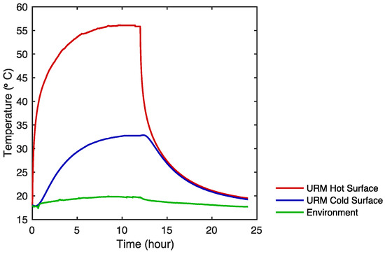
Figure 8.
Temperature profiles on both sides of unreinforced masonry (URM) specimens.
NHL and GPM results were arranged in the same graph (Figure 9) in order to compare the thermal behavior of the specimens during the test. Again, the orange and red curves represent the hot side of NHL and GPM, respectively, while the blue and cyan ones represent the cold side of GPM and NHL, respectively. In the heating stage, NHL exhibited a faster increase of temperature up to the peak (~56 °C), with respect to GPM. Nonetheless, the latter reached a higher temperature (~57 °C) at steady-state condition. In the cooling stage, both the specimens exhibited a delay in the decrease phase of the curve, which took longer time with respect to URM. Thus, the thermal inertia of the wall was increased by applying the mortar layer. The difference recorded between the peaks of cyan and blue curves suggests that a substantial change in thermal behavior is obtained. More details about this change can be appreciated analyzing the results reported in Table 3.
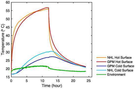
Figure 9.
Temperature profiles on both sides of Natural Hydraulic Lime (NHL) and GeoPolymer Mortar (GPM) specimens.
Finally, a comparison between temperature profiles on both sides of FRCM and FRGM is reported in Figure 10. The behavior of the curves is similar those in Figure 9, despite different values were recorded. The orange curve (FRCM) reached a peak at ~57 °C, while the red one (FRGM) exhibited a slower increase to ~60 °C. The blue curve drew the cooling stage of FRGM and the cyan one of FRCM, exhibiting a small increase (due to thermal inertia) before the decrease in temperature. Even in this case, the cyan and blue curves exhibited a difference linked to different thermal transmittance. The estimated thermal transmittances are collected in Table 4.
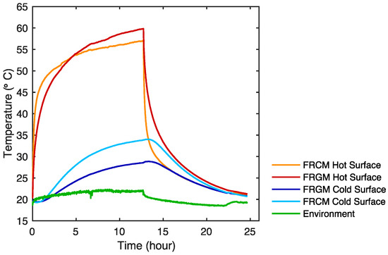
Figure 10.
Temperature profiles on both sides of FRCM and FRGM specimens.
Table 4.
Thermal test results.
The so-collected data were used to compute the thermal resistance and transmittance of the wall according to Equations (1)–(2). Moreover, the ratio between the sample transmittance and URM transmittance was also reported in Table 4. A thermal transmittance equal to 2.082 W m−2 K−1 was estimated for URM. The lime-based retrofitting systems exhibited lower thermal transmittances, equal to 1.862 W m−2 K−1 (FRCM) and 1.554 W m−2 K−1 (NHL). Thus, the application of a layer which is not generally oriented to thermal insulation can lead to a thermal transmittance reduction, as shown in Table 3. In fact, the FRCM and NHL manifested a reduction of 11% and 25%, respectively. Conversely, geopolymer-based retrofitting systems are prone to be adopted for an integrated system, aimed to improve both thermal capacity and mechanical resistance. A thermal transmittance equal to 1.126 W m−2 K−1 was computed for FRGM and equal to 1.051 W m−2 K−1 for GPM. Indeed, FRGM and GPM exhibited a greater reduction of thermal transmittance of 46% and 50%, respectively, with respect to URM panels.
5. Conclusions and Future Challenges
An experimental campaign was carried out in order to investigate both energy and mechanical improvement of masonry panels through the application of different retrofitting systems. In detail, the main focus is the comparison of a traditional FRCM system and an innovative one, namely FRGM. Moreover, the matrices of both systems were also applied to the panels without any fabric and tested, as well.
The mechanical tests were intended to determine the shear strength, shear modulus and ductility of the samples. The shear strength gains of the innovative solutions (i.e., GPM and FRGM) were comparable with traditional ones and a minimum gain of 53% was obtained. Furthermore, the increase of ductility for geopolymer-based systems is much higher with respect to that obtained for other samples and a relevant difference of the failure modes has been also observed. As a matter of fact, GPM and FRGM samples did not exhibit any substrate-matrix detachment, pointing out a better behavior in terms of bond strength.
The thermal tests recorded a substantial difference related to the adopted mortar. As a matter of fact, the thickness of the AR-glass fabric is much smaller than panel and mortar ones. As a consequence, the thermal contribution of the fabric can be neglected, and the thermal tests simply compared the influence of NHL-mortar and GPM-mortar applied with different thicknesses, i.e., 1.5 cm and 3 cm. The results proved that GPM and FRGM are solutions more suitable for an integrated structural and energy retrofitting system, since the recorded thermal transmittance reduction is much higher. Even a large NHL thickness does not provide the thermal capacity of a smaller GPM thickness, as above stated.
Finally, the innovative proposed retrofitting solutions demonstrated to be suitable for achieving both a structural and energy behavior enhancement. In particular, the mechanical improvement in terms of resistance is similar to the one of traditional solution, but with a substantial increment of ductility. Additionally, the innovative solutions manifested an increase of the thermal insulation capacity.
Future challenges refer to the use of CRM system and a further FRGM application with a fabric different from the glass fiber. Experimentations are currently in progress. Moreover, the out-of-plane behavior of the retrofitted masonry needs to be experimentally investigated in order to cover all the seismic capacities.
Author Contributions
Conceptualization, F.L. and A.C.; methodology, P.L. and M.A.A.; validation, P.L. and M.A.A.; formal analysis, F.L.; investigation, F.L. and A.C.; resources, M.A.A.; data curation, F.L.; writing—original draft preparation, F.L. and A.C.; writing—review and editing, P.L. and M.A.A.; visualization, P.L. and M.A.A.; supervision, P.L. and M.A.A.; project administration, M.A.A.; funding acquisition, M.A.A. All authors have read and agreed to the published version of the manuscript.
Funding
Prin2017 “SURMONT—“Innovative systems based on inorganic mortar and non-metallic reinforcement for the upgrade of masonry structures and non-structural elements”.
Data Availability Statement
The data presented in this study are available on request from the corresponding author.
Acknowledgments
The authors would acknowledge also Dennert Poraver GmbH for suppling expanded grass aggregates.
Conflicts of Interest
The authors declare no conflict of interest.
References
- Cascardi, A.; Lerna, M.; Micelli, F.; Aiello, M.A. Discontinuous FRP-confinement of masonry columns. Front. Built Environ. 2019, 5, 147. [Google Scholar] [CrossRef]
- Cascardi, A.; dell’Anna, R.; Micelli, F.; Lionetto, F.; Aiello, M.A.; Maffezzoli, A. Reversible techniques for FRP-confinement of masonry columns. Constr. Build. Mater. 2019, 225, 415–428. [Google Scholar] [CrossRef]
- Ormeno, M.; Jing, J.; Rogers, R.; del Rey Castillo, E. Capacity of Diaphragm Strengthened with Frp: Comparison Between Aci 440.2 R and In-Situ Tests. In Proceedings of the 2019 Pacific Conference on Earthquake Engineering (NZSEE/PCEE), SkyCity, AK, New Zealand, 4–6 April 2019. [Google Scholar]
- Hamilton Iii, H.R.; Dolan, C.W. Flexural capacity of glass FRP strengthened concrete masonry walls. J. Compos. Constr. 2001, 5, 170–178. [Google Scholar] [CrossRef]
- Chen, J.F.; Teng, J.G. Shear capacity of FRP-strengthened RC beams: FRP debonding. Constr. Build. Mater. 2001, 17, 27–41. [Google Scholar] [CrossRef]
- Oliveira, D.V.; Basilio, I.; Lourenço, P.B. Experimental behavior of FRP strengthened masonry arches. J. Compos. Constr. 2010, 14, 312–322. [Google Scholar] [CrossRef]
- Valluzzi, M.R.; Valdemarca, M.; Modena, C. Behavior of brick masonry vaults strengthened by FRP laminates. J. Compos. Constr. 2001, 5, 163–169. [Google Scholar] [CrossRef]
- Micelli, F.; Cascardi, A.; Marsano, M. Seismic Strengthening of a Theatre Masonry Building by Using Active Frp Wires. In Proceedings of the 16th International Brick and Block Masonry Conference, Padova, Italy, 26–30 June 2016; pp. 753–761. [Google Scholar]
- Cascardi, A.; Micelli, F.; Aiello, M.A. Analytical model based on artificial neural network for masonry shear walls strengthened with FRM systems. Compos. Part. B Eng. 2016, 95, 252–263. [Google Scholar] [CrossRef]
- Cascardi, A.; Aiello, M.A.; Triantafillou, T. Analysis-oriented model for concrete and masonry confined with fiber reinforced mortar. Mater. Struct. 2017, 50, 202. [Google Scholar] [CrossRef]
- Cascardi, A.; Longo, F.; Micelli, F.; Aiello, M.A. Compressive strength of confined column with Fiber Reinforced Mortar (FRM): New design-oriented-models. Constr. Build. Mater. 2016, 156, 387–401. [Google Scholar] [CrossRef]
- Cascardi, A.; Micelli, F.; Aiello, M.A. FRCM-confined masonry columns: Experimental investigation on the effect of the inorganic matrix properties. Constr. Build. Mater. 2018, 186, 811–825. [Google Scholar] [CrossRef]
- Azam, R.; Soudki, K. FRCM strengthening of shear-critical RC beams. J. Compos. Constr. 2014, 18. [Google Scholar] [CrossRef]
- Wakjira, T.G.; Ebead, U. FRCM/internal transverse shear reinforcement interaction in shear strengthened RC beams. Compos. Struct. 2018, 201, 326–339. [Google Scholar] [CrossRef]
- D’Ambrisi, A.; Focacci, F.; Caporale, A. Strengthening of masonry–unreinforced concrete railway bridges with PBO-FRCM materials. Compos. Struct. 2013, 102, 193–204. [Google Scholar] [CrossRef]
- Su, M.N.; Wei, L.; Zhu, J.H.; Ueda, T.; Guo, G.P.; Xing, F. Combined impressed current cathodic protection and FRCM strengthening for corrosion-prone concrete structures. J. Compos. Constr. 2019, 23. [Google Scholar] [CrossRef]
- Ombres, L.; Verre, S. Numerical modeling approaches of FRCMs/SRG confined masonry columns. Front. Built Environ. 2019, 5. [Google Scholar] [CrossRef]
- Aljazaeri, Z.R.; Myers, J.J. Fatigue and flexural behavior of reinforced-concrete beams strengthened with fiber-reinforced cementitious matrix. J. Compos. Constr. 2017, 21. [Google Scholar] [CrossRef]
- Loreto, G.; Leardini, L.; Arboleda, D.; Nanni, A. Performance of RC slab-type elements strengthened with fabric-reinforced cementitious-matrix composites. J. Compos. Constr. 2014, 18. [Google Scholar] [CrossRef]
- Bencardino, F.; Nisticò, M.; Verre, S. Experimental investigation and numerical analysis of bond behavior in SRG-strengthened masonry prisms using UHTSS and stainless-steel fibers. Fibers 2020, 8, 8. [Google Scholar] [CrossRef]
- Ombres, L.; Verre, S. Analysis of the behavior of FRCM confined clay brick masonry columns. Fibers 2020, 8, 11. [Google Scholar] [CrossRef]
- National Research Council (CNR). Guide for the Design and Construction of Externally Bonded Fibre Reinforced Inorganic Matrix Systems for Strengthening Existing Structures; Consiglio Nazionale delle Ricerche: Rome, Italy, 2020. [Google Scholar]
- Scopus—Document Search. Available online: https://www.scopus.com/ (accessed on 1 August 2020).
- Longo, F.; Lassandro, P.; Moshiri, A.; Phatak, T.; Aiello, M.A.; Krakowiak, K.J. Lightweight geopolymer-based mortars for the structural and energy retrofit of buildings. Energy Build. 2020, 225. [Google Scholar] [CrossRef]
- Longo, F.; Cascardi, A.; Lassandro, P.; Aiello, M.A. A new Fabric Reinforced Geopolymer Mortar (FRGM) with mechanical and energy benefits. Fibers 2020, 8, 49. [Google Scholar] [CrossRef]
- Del Zoppo, M.; di Ludovico, M.; Prota, A. Analysis of FRCM and CRM parameters for the in-plane shear strengthening of different URM types. Compos. Part. B Eng. 2019, 171, 20–33. [Google Scholar] [CrossRef]
- Pohoryles, D.A.; Maduta, C.; Bournas, D.A.; Kouris, L.A. Energy performance of existing residential buildings in Europe: A novel approach combining energy with seismic retrofitting. Energy Build. 2020, 223. [Google Scholar] [CrossRef]
- Gattesco, N.; Boem, I. Experimental and analytical study to evaluate the effectiveness of an in-plane reinforcement for masonry walls using GFRP meshes. Constr. Build. Mater. 2015, 88, 94–104. [Google Scholar] [CrossRef]
- Gattesco, N.; Boem, I.; Dudine, A. Diagonal compression tests on masonry walls strengthened with a GFRP mesh reinforced mortar coating. Bull. Earthq. Eng. 2015, 13, 1703–1726. [Google Scholar] [CrossRef]
- Borri, A.; Corradi, M.; Sisti, R.; Buratti, C.; Belloni, E.; Moretti, E. Masonry wall panels retrofitted with thermal-insulating GFRP-reinforced jacketing. Mater. Struct. 2016, 49, 3957–3968. [Google Scholar] [CrossRef]
- Longo, F.; Cascardi, A.; Lassandro, P.; Sannino, A.; Aiello, M.A. Mechanical and thermal characterization of FRCM-Matrices. In Key Engineering Materials; Trans Tech Publications Ltd.: Zurich, Switzerland, 2016; Volume 817, pp. 189–194. [Google Scholar]
- Micelli, F.; Sciolti, M.S.; Leone, M.; Aiello, M.A.; Dudine, A. Shear behaviour of Fiber Reinforced Mortar strengthened masonry walls built with limestone blocks and hydraulic mortar. In Proceedings of the 16th International Brick and Block Masonry Conference, Padova, Italy, 26–30 June 2016. [Google Scholar]
- Yardim, Y.; Lalaj, O. Shear strengthening of unreinforced masonry wall with different fiber reinforced mortar jacketing. Constr. Build. Mater. 2016, 102, 149–154. [Google Scholar] [CrossRef]
- Marcari, G.; Basili, M.; Vestroni, F. Experimental investigation of tuff masonry panels reinforced with surface bonded basalt textile-reinforced mortar. Compos. Part. B Eng. 2017, 108, 131–142. [Google Scholar] [CrossRef]
- Giaretton, M.; Dizhur, D.; Garbin, E.; Ingham, J.M.; da Porto, F. In-plane strengthening of clay brick and block masonry walls using textile-reinforced mortar. J. Compos. Constr. 2018, 22. [Google Scholar] [CrossRef]
- Casacci, S.; Gentilini, C.; di Tommaso, A.; Oliveira, D.V. Shear strengthening of masonry wallettes resorting to structural repointing and FRCM composites. Constr. Build. Mater. 2019, 206, 19–34. [Google Scholar] [CrossRef]
- Bournas, D.A. Concurrent seismic and energy retrofitting of RC and masonry building envelopes using inorganic textile-based composites combined with insulation materials: A new concept. Compos. Part. B Eng. 2018, 148, 166–179. [Google Scholar] [CrossRef]
- Gkournelos, P.D.; Bournas, D.A.; Triantafillou, T.C. Combined seismic and energy upgrading of existing reinforced concrete buildings using TRM jacketing and thermal insulation. Earthq. Struct. 2019, 16, 625–639. [Google Scholar]
- UNI EN. Metodi di Prova per Pietre Naturali—Determinazione della Resistenza a Compressione Uniassiale; Cen-Cenelec: Bruxelles, Belgium, 2007. [Google Scholar]
- UNI EN. Metodi di Prova per Malte per Opere Murarie—Determinazione della Resistenza a Flessione E a Compressione della Malta Indurita; UNI: Milan, Italy, 2007. [Google Scholar]
- UNI EN. Metodi di Prova per Muratura—Determinazione della Resistenza a Compressione; UNI: Milan, Italy, 2001. [Google Scholar]
- ISO. Textiles—Tensile Properties of Fabrics—Part 1: Determination of Maximum Force and Elongation at Maximum Force Using the Strip Method; ISO: Geneva, Switzerland, 2013. [Google Scholar]
- ASTM International. Standard Test Method for Diagonal Tension (Shear) in Masonry Assemblages; ASTM International: West Conshohocken, PA, USA, 2010. [Google Scholar]
- Howell, J.R.; Siegel, R.; Mengüç, M.P. Thermal Radiation Heat Transfer; CRC Press: Boca Raton, FL, USA, 1969. [Google Scholar]
- Albatici, R.; Passerini, F.; Tonelli, A.M.; Gialanella, S. Assessment of the thermal emissivity value of building materials using an infrared thermovision technique emissometer. Energy Build. 2013, 6, 33–40. [Google Scholar] [CrossRef]
- Emmel, M.G.; Abadie, M.O.; Mendes, N. New external convective heat transfer coefficient correlations for isolated low-rise buildings. Energy Build. 2007, 39, 335–342. [Google Scholar] [CrossRef]
- Donatelli, A.; Aversa, P.; Luprano, V.A.M. Set up of an experimental procedure for the measurement of thermal transmittances via infrared thermography on lab-made prototype walls. Infrared Phys. Technol. 2016, 79, 135–143. [Google Scholar] [CrossRef]
- Kontoleon, K.J.; Theodosiou, T.G.; Tsikaloudaki, K.G. The influence of concrete density and conductivity on walls’ thermal inertia parameters under a variety of masonry and insulation placements. Appl. Energy 2013, 112, 325–337. [Google Scholar] [CrossRef]


Publisher’s Note: MDPI stays neutral with regard to jurisdictional claims in published maps and institutional affiliations. |
© 2021 by the authors. Licensee MDPI, Basel, Switzerland. This article is an open access article distributed under the terms and conditions of the Creative Commons Attribution (CC BY) license (http://creativecommons.org/licenses/by/4.0/).