1. Introduction
Magma fragments expelled by volcanic eruptions give rise to pyroclasts, which can be made up of: (1) small glass particles with a very highly specific surface area; (2) larger fragments that, when solidified, produce scoriae and pumices and contain inner gas. As a consequence of this process, pyroclastic rocks have low density and, therefore, high porosity, such that the characterization and geomechanical applications are very special.
In this type of low-density volcanic material, when an external load of low magnitude is applied, the resistant and deformational characteristics resemble conventional rocks; however, by increasing the load level and raising the internal stress range, the links between the particles are broken and a destructuring process is induced, meaning that sudden deformations are inferred, generating a great danger for the structures that must be supported. This sudden process is called as mechanical collapse, and it produces a reorganization of particles, after which a more compact structure is formed than the one that initially existed.
There is great interest in depicting a theoretical and practical framework to describe and to estimate the strength and deformability properties of the low- density volcanic pyroclasts in the field of civil engineering and building in volcanic areas. To face the design and calculation of the applications, it is necessary to use a correct failure law, which adequately represents the behavior of pyroclasts. Thus, the failure criterion by Serrano et al. [
1], obtained from about 300 samples of volcanic materials from the Canary Islands, is applied to the problem of calculating a shallow foundation, establishing the stress state to infer the breakage mechanism in the ground.
The use of numerical methods and the progress of computational geomechanics have allowed access to the practical calculation of more sophisticated bearing capacity problems, involving anisotropic rock masses [
2,
3], the presence of a water table in the rock [
4], the shape of the foundation [
5,
6], and the interaction with other structural elements, such as tunnels [
7], bilayer rock under the footing [
8], or the dynamic response of the foundation [
9,
10,
11]. In this paper, the numerical formulation DLO (discontinuity layout optimization) is applied to analyze volcanic rocks of low density.
The application of the DLO method is shown for a resolution of the general problem that can be approached in a practical and rigorous way. For an adequate validation of the DLO method, the failure wedges and the bearing capacity values of simplified situations that can be addressed by the theoretical solution by Serrano et al. [
12] are compared. Additionally, such failure law is implemented in finite differences, using FLAC [
13], in order to validate the numerical solution obtained with DLO.
2. Background
2.1. Geomechanical Characterization of Pyroclasts
The unique geomechanical characterization of pyroclasts has been observed in various engineering studies that have been carried out in volcanic areas, such as in some dams, for example Campitos and Ariñez (Tenerife) [
14,
15], where a series of tests (triaxial and isotropic collapse) to determine the load conditions that produce mechanical collapse in their foundation materials were performed.
An extensive study of the characterization of the strength and deformability of the volcanic materials of very different densities based on different field data, tests in new samples, bibliographic studies, and geotechnical studies have been carried out. The investigations have extended to very different areas and types of materials: in the Canary Islands [
1,
16,
17,
18,
19,
20,
21,
22]; with Neapolitan Yellow Tuff [
23,
24,
25,
26]; with fine-grained tuff [
27,
28]; with coarse-grained tuff, such as Pozzolana Nera [
29,
30,
31]; in the ignimbrites [
32]; through local studies, such as the one on “Ohya Stone” Green Tuff from Japan [
33]; or more general studies, for example, that of Teymen [
34].
From the study of low-density volcanic materials carried out by the researchers, it has been possible to conclude that the geomechanical behavior of these materials is highly conditioned by their structure. With low confining levels, the stress–strain behavior can be considered as elastic and linear, however after reaching the maximum stress (peak load), a great fragility of the material is appreciated, which is more marked at lower confinement.
Therefore, the study of problems applied to low-density volcanic rocks requires considering a markedly non-linear failure law that complicates the numerical treatment.
2.2. Discontinuity Layout Optimization Method (DLO)
The characteristic lines method [
35] has been used to solve the bearing capacity problem in Mohr-Coulomb soils and in conventional rocks. From this method, it has been possible to obtain the global breaking mechanism in the ground and predict values of support capacity, resulting in a reliable and powerful method. However, its use requires certain hypotheses that, in many cases, excessively particularize the problem and hinder the practical application in civil engineering, making it necessary to establish a more flexible method that allows users to extend, in a simple way, the boundary conditions that define the problem to general situations.
Finite element limit analysis (FELA) has been widely used to obtain ultimate loads without the need to discretize the equations over time or vary the external load incrementally, proving its effectiveness in conventional materials of soil and rock mechanics [
36,
37]. Other authors [
38,
39,
40] have used a limit analysis of lower bound finite elements, in combination with mathematical optimization procedures, to obtain solutions in non-linear rock masses using a modified Hoek-Brown [
41] yield criterion. They used linear or second-order programming to consider the non-linear behavior of failure criterion [
42]. However, the results obtained are often very dependent on the finite element mesh, making it necessary to utilize adaptive remeshing procedures [
43].
Smith and Gilbert [
43] developed the discontinuity layout optimization (DLO) method, and more recent research [
44,
45,
46] has optimized the calculation scheme and selection of trajectories by means of nodal connection, which created a greater resolution efficiency to address more general problems, as well as incorporating breakage mechanisms that involve rotations. Different examples applied to soil mechanics have been shown by Smith et al. [
47], who proposed the DLO method as an alternative to the classical procedures to obtain a safety factor.
Since then, investigations have emerged [
48,
49,
50] that applied the DLO method to different support capacity problems, which allowed the involvement of particular characteristics related to geometry, short- or long-term situations, interaction of foundation elements, joint failure structural and geotechnical foundations, multilayer grounds, and complex foundation configurations in general.
Recent studies [
2,
51,
52] have shown the application of the DLO method for grounds with no linear law. To increase the application possibilities of this numerical method (DLO), the present research solves the bearing capacity of foundations on rock masses following a highly non-linear failure law, referred to as volcanic pyroclasts [
1]. The linearization of this failure law is presented as a crucial process for its correct application and its effectiveness is validated with the theoretical solution [
12] in simple configurations where the theoretical solution is applicable. Likewise, results are compared with the finite difference method by means of a contrasted geotechnical software.
3. Formulation of the Failure Criterion
3.1. Mathematical Formulation (Parabolic Criterion)
Based on the empirical study performed on volcanic pyroclasts by Serrano et al. [
1], the parabolic criterion was suggested as a strength criterion for low-density pyroclastic materials. Before its development, other authors, such as [
15,
27,
53], proposed different yield surfaces for low-density and collapsible materials, which promoted the empirical study of Serrano et al. [
1] and the parabolic criterion considered in this document.
The parabolic criterion, in Cambridge variables
and
, for low-density volcanic pyroclastics indicated by Serrano et al. [
1] is:
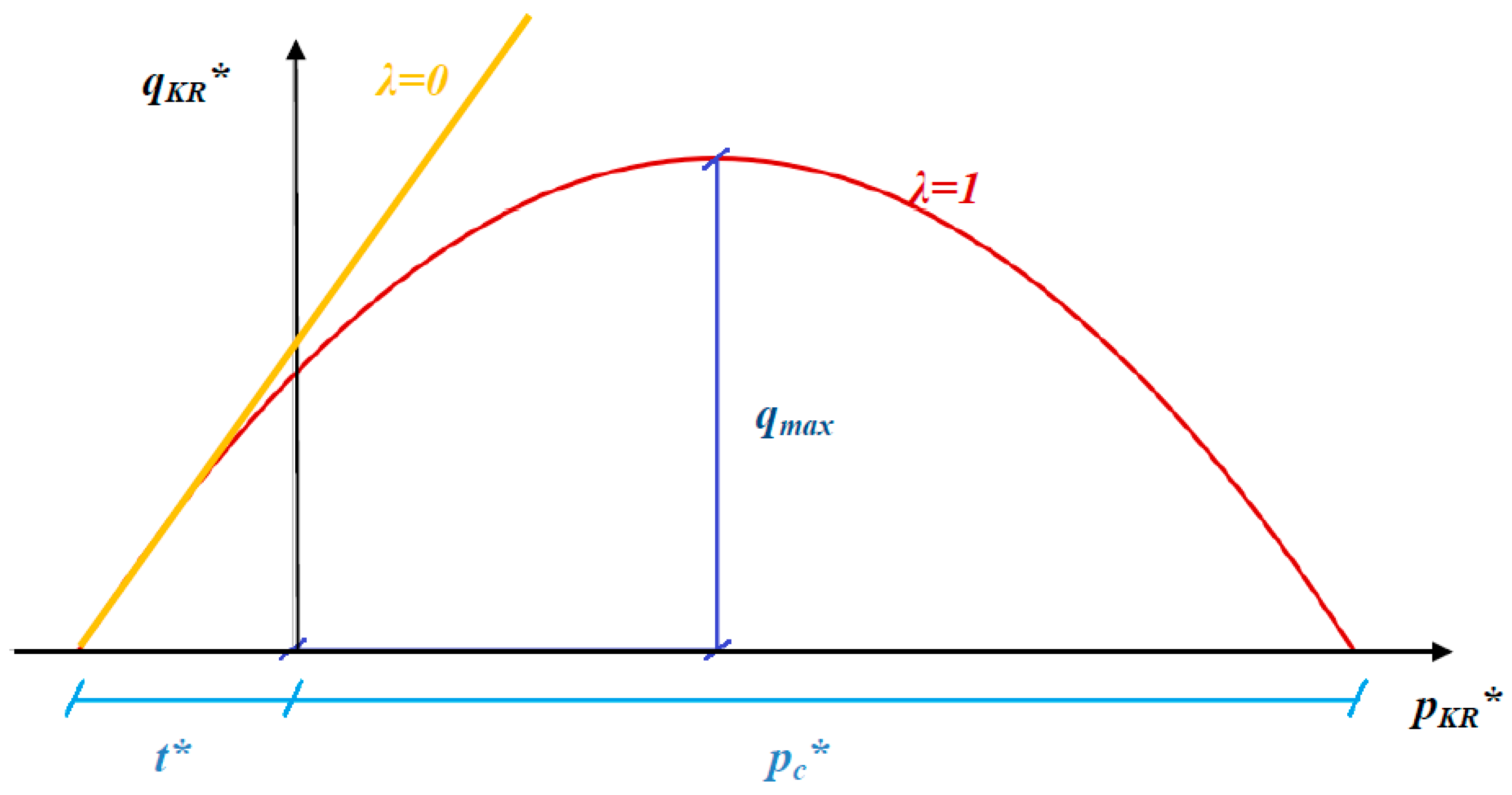
In law (1), represented in
Figure 1, there are four parameters (
,
and
).
is the isotropic tensile strength and
is the isotropic compressive strength (the following notation is adopted:
). The ratio
is referred to as the tensile coefficient ζ.
is a frictional parameter that can be determined by triaxial tests for low pressures, depending on the value of the initial instantaneous friction angle (
).
The explicit variable
is a shape parameter that represents a non-linear extension from the Mohr-Coulomb strength criterion, which is verified when
, as shown in
Figure 2 in Cambridge variables (
), where
. Parameter
is obtained from experimentation, with values between
.
To complement this study, Table 1 includes a compilation of outcomes obtained from [
1,
54], which shows the values of the four variables of the parabolic criterion in failure law (1). With this table, it is possible to obtain an order of magnitude for every parameter required. For most pyroclasts, the parameter
ζ is about 1–5%. In addition, almost all rocks have a
λ very close to 1 and all materials, with some exceptions, have a parameter
M between 1.5 and 3.
3.2. Identification of the Failure Zones
Considering the parabolic criterion with
, the concept of an instantaneous friction angle (
) was defined in [
55], using Hill-Lambe variables, as:
Within the range of , instantaneous friction angle may be non-real. If , then is a real value, and the failure is plastic, forming vertical and inclined failure planes caused by the lack of confining pressure. If , then is an imaginary value, and the plastic failure does not exist. Failure occurs in this scenario by the destructuring of the specimen (mechanical collapse). Depending on the friction parameter , two different destructuring failure mechanisms may exist along the strength criterion: compression destructuring (RCD) occurs when , and tensile destructuring (RDT) exists when along with RCD.
According to
Table 1, the values of
are essentially between 1.5 and 3, with no value registered higher or equal to 3. As a result of that, RCD is the only destructuring or mechanical collapse failure mechanism considered in this paper, as illustrated in
Figure 3.
4. Bearing Capacity
The solution for bearing capacity of a strip foundation on a rock with an associative dilatancy angle, collapsible failure criterion, perfect plasticity, weightless rock media, and plane strain is proposed. The general model that can be solved by mathematical formulation (including sloping ground) is shown in
Figure 4 and it has the free boundary (boundary 1) where a uniform load
is applied and the boundary of foundation (boundary 2) represented by a uniform load
. A singular point allows dividing both boundaries, so that this point is the end of the foundation on boundary 2 and the beginning of boundary 1, which, in general, can be inclined by an angle
α with respect to the horizontal.
5. Analytical Solution
In [
12], for the general model that can be solved by mathematical formulation (including sloping ground), two possible breakage wedges in boundary 2 (failure for plastic shear and destructuring,
Figure 5) were identified using the following simplifying hypotheses: homogeneity, plane strain, isotropy, associative dilatancy angle, and perfectly plastic rock, following the law of strength suggested by (1)—the foundation is at the edge of the slope and rock mass is assumed weightless.
Thus, Serrano et al. [
12] obtained a bearing capacity (
Ph) equal to:
For the failure for plastic shear with vertical load on the foundation:
where
, with
the instantaneous friction angle at boundary 2.
In the failure of destructuring, the Rankine-1 and Prandtl regions disappear, and the characteristic lines and the Rankine-2 region vanish. The destructuring produces a breakage wedge of angle
β under the footing, although the bearing capacity is constant:
6. Resolution Method: Discontinuity Layout Optimization Method
The discontinuity layout optimization method (DLO) [
43] uses the limit analysis method, although it does not presuppose a particular mode of breakage. It requires the user to identify all possible failure mechanisms. In this way, it is necessary to solve an optimization problem among all the possible failure wedges that result from joining the different nodes that discretize the medium, so that failure mode with minimum energy is considered.
The DLO consumes few computational resources and is very suitable for support capacity problems, since it is consistent with respect to the stability, blocking, and convergence of the calculation scheme [
47], and a higher precision of the results can be achieved using a higher density of nodes so that the result gives rise to an upper-bound solution [
47].
6.1. Mathematical Formulation
The optimization problem of the DLO method that minimizes the energy of the set of lines of discontinuity can be formulated as follows [
43]:
where
λ is the adequacy factor—by multiplying the specified load by this factor, the collapse of the medium is produced.
The objective function has the following restrictions:
where
fD indicates dead loads and
fL represents live loads, and
dT = {
s1, n1, s2, n2, …, sm} refers to the relative shear
si and normal movements
ni between blocks at discontinuity
i. Vector
gT = {
c1 l1, c1 l1, c2 l2, c2 l2, …, cm lm} contains cohesive shear strength
ci multiplied by length
li of discontinuity
i.
p is a vector of plastic multipliers,
B is a compatibility matrix with direction cosines, and
N is a flow matrix. LP variables are
d and
p.
In terms of a single yield-line, the shear and normal displacement at discontinuity
i must verify:
where
αi and
βi are the x-axis and y-axis direction cosines for discontinuity
i.
The plastic flow law constraint for the yield-line will simply be:
where
and
are plastic multiplier variables, constrained to take only positive values, and
φi is the angle of friction (dilation) and
ni is the normal displacement accompanying the sliding.
Contribution by the dead and live loads to the work balance equation:
where
Wi is the total weight above discontinuity
i.
Force vectors have the forms and , where fsDi, fnDi, fsLi, and fnLi, represent, respectively, the shear and normal dead and live loads applied locally at discontinuity i.
Contribution by this yield-line to the work balance equation:
where
li and
ci are, respectively, the length and the cohesive shear strength of discontinuity
i.
6.2. Hypotheses Adopted
It is necessary to define analogous soil–structure interaction conditions so that the results obtained numerically are comparable with the analytical solution [
12]. In particular, for a foundation directly supported by the ground, a rigid or flexible slab situation can be generated that depends on the different Young’s coefficients of the footing and the ground. In the theoretical solution, this situation cannot be simulated as it does not depend on deformational parameters; however, in the FDM numerical solution, it can incorporate this consideration through the conditions of the contact points of the footing and the rock. In the DLO model, initial simulations have been carried out to adequately study which stiffness situation is induced in the models, concluding that the best approximation between the theoretical solution and the DLO method corresponds to a rigid support. In this way, a rigid foundation block is adopted subjected to a uniform load that allows all the contact points between the foundation and the ground to have the same displacement. For the application of the numerical calculation software, the linearization of the failure criterion (1) is necessary; however, the linearization admits indefinite variants that can generate considerable variations in the results [
6,
52]. The linear approximation requires a large number of intervals of secant lines (lower envelope) or tangent lines (upper envelope) to obtain adequate precisions, which can generate high computational resources. This linear approximation is presented in
Figure 6. In this research, different numbers of segments have been analyzed to linearize the failure surface, so that no considerable improvement in efficiency has been found above 10 intervals.
The limit analysis allows obtaining the lines that produce the lowest adequacy factor (λ) [
56]. The indicated linearization methodology implies that a set of linear Mohr-Coulomb materials are considered to solve the problem. Thus, new equations (2) are generated that define the medium, the resolution of which raises the optimization problem that allows obtaining the value of the minimum adequacy factor.
6.3. Model DLO
The DLO models are implemented using the GEO software of LimitState [
56], where it is necessary to introduce the failure criterion (1) through the linearization indicated in
Figure 6.
A rectangular boundary is used for the rock mass, and due to the symmetry conditions considered, it allows for the representation of only half of the footing with the symmetry conditions at the lower and right edges.
The 10 m foundation block is introduced (5 m due to the symmetry in the model), which allows a rigid support on the ground through the contact nodes.
The models have a different size depending on the extent of the wedge of rupture that occurs in the ground, so that if the boundaries are crossed by this mechanism of rupture, it is necessary to grow the rectangle of ground represented (this process has been carried out in all simulations using an interactive trial and error process).
The number of nodes makes it possible to define the potential breakage lines to be optimized to apply the DLO method and, therefore, defines the precision of the discretization, so that an adequate balance is reached between the precision of the solution and computational costs. In our case, a node density for a nodal spacing of 1/15 of the width of the foundation has been used.
This research is focused on showing the resolution possibilities of the DLO method, considering the unique failure criteria of pyroclastic materials, and all the calculations carried out have considered horizontal ground. An example is shown in
Figure 7.
7. Validation Method: Finite Differences Method
In order to compare the results obtained applying the numerical method proposed in the present study, 2D models were used to calculate the cases by finite difference method (FDM), employing commercial code FLAC. In the finite differences method, every derivative in the set of governing equations is replaced directly by an algebraic expression written in terms of the field variables (stress or displacement) at discrete points in space; these variables are undefined within elements. Using the approach of Wilkins [
57], boundaries can be of any shape, and any element can have any property value.
In order to use the collapsible failure law (1), it has been necessary to implement it using the user-defined programming module, which allows incorporating one’s own constituent models using C++. The numerical implementation uses a linear approximation, whereby the nonlinear failure surface is continuously approximated by the Mohr-Coulomb tangent at the current stress level indicated by the minor main stress.
The numerical model was implemented in such a way that the soil–structure interaction characteristics did not influence the result (structural foundation stiffness and roughness in contact). For this, the load was applied directly on the nodes of the ground model (surface). The plane strain condition was used in a symmetric model, where half of the footing (5m) was represented considering horizontal ground (
Figure 8). In this way, a 40 × 25 m numerical calculation mesh m (20 × 25 m in symmetry) was generated with 1066 evenly spaced nodes. An associated dilation angle was assigned.
The FDM reaches the support capacity of the ground when the continuous medium is not able to support a higher level of load and responds by deforming indefinitely and, therefore, forming an internal failure mechanism. In FLAC, the load is applied to the nodes while introducing velocity increases, so that when considering the mass concentrated in them, load variations are generated that allow the load capacity to be reported.
8. Results and Discussion
Eight analysis cases, presented in
Table 2, were studied, where the values of the adopted parameters and the bearing capacity results obtained by the DLO method are shown.
An isotropic collapse pressure = 1 MPa, frictional parameter M values of 1.5 and 2.5, tensile coefficients equal to 1% and 5%, and external load SC = 10 kPa and 500 kPa have been used.
As can be seen in
Table 2, the values for both numerical methods were quite close in relation to the analytical method, however better results were obtained with the DLO method, where errors of less than 8% were found.
Figure 9 shows the results and breakage mechanisms obtained for cases 7 and 8. As can be seen, when the external overload increases, the failure mode changes, since the confinement increases and the destructuration is reached, locating the failure under the foundation. In case 7, the failure corresponds to the general mechanism of conventional soils and rocks, as they have a low confining load, while case 8 shows the localized failure under the foundation, typical of low-density volcanic rocks, according to the knowledge learned on the volcanic rocks.
Figure 10 shows results with FLAC, where the displacement under the footing at the start of failure for the maximum load can also be observed. In
Figure 10, the vertical displacement in case 8 is shown, which in the theoretical solution corresponds to a destructuring failure. Thus, the zone of movement affection is located under the footing developing a small wedge.
From the study carried out, some considerations have been revealed. On the one hand, analytical solutions do not allow general configurations for their resolution and are limited to a few possible analysis cases. On the other hand, it is possible to use other numerical methods to solve the problem, but they face two difficulties, which in DLO are easily solved: (1) The implementation of the failure criterion that must be programmed for the numerical resolution and that, in the case of conventional numerical methods such as FEM or FDM, needs to be coupled to the ground deformability equations (constitutive equations), which extraordinarily complicates its programming. In the case of DLO, the result is independent of the soil deformability equations, simplifying the calculation process and making it much easier to implement. (2) Numerical convergence and stability and solution blocking problems must be addressed and studied in conventional numerical solutions, since the numerical process involves compatibility, constitutive, and boundary equations. In the DLO, the solutions evaluate the minimum energy path among all the possible ones (selecting the potentially possible ones by optimization methods) and, therefore, the numerical problems described are considerably minimized.
9. Conclusions
In this research, the ultimate bearing capacity of a strip foundation in a collapsible medium, with associative dilatancy, perfect plasticity, weightless rock media, and plane strain, was studied using the DLO (discontinuity layout optimization) numerical method. Two breakage shapes were identified in the pyroclasts: plastic wedge and destructuring. In addition, numerical validation was performed using the finite difference method, FLAC and an analytical method [
12] using simplified configurations, obtaining good contrast results, with better results obtained from the DLO method. It was also shown that the destructuring coincided under the foundation in both numerical models.
Author Contributions
Conceptualization, R.G.; methodology, R.G. and M.Á.M.; validation, M.Á.M.; writing—original draft preparation, M.Á.M. and R.G.; writing—review and editing, M.Á.M. and R.G.; supervision, L.E.H.-G., C.O.M., and H.P. All authors have read and agreed to the published version of the manuscript.
Funding
This research was funded by the Universidad Politécnica de Madrid from the grant with reference VMENTORUPM21RAGA.
Institutional Review Board Statement
Not applicable.
Informed Consent Statement
Not applicable.
Data Availability Statement
Not applicable.
Acknowledgments
The research described in this paper was financially supported by the Universidad Politécnica de Madrid from the grant with reference VMENTORUPM21RAGA, from the university’s own program to carry out research and innovation projects.
Conflicts of Interest
The authors declare no conflict of interest.
References
- Serrano, A.; Perucho, A.; Conde, M. Yield criterion for low-density volcanic pyroclasts. Int. J. Rock Mech. Min. Sci. 2016, 86, 194–203. [Google Scholar] [CrossRef]
- Galindo, R.; Millán, M. An accessible calculation method of the bearing capacity of shallow foundations on anisotropic rock masses. Comput. Geotech. 2020, 131, 103939. [Google Scholar] [CrossRef]
- Cao, Z.; Xu, B.; Cai, Y.; Galindo-Aires, R.; Li, C. Solution of the Ultimate Bearing Capacity at the Tip of a Pile in Anisotropic Discontinuous Rock Mass Based on the Hoek–Brown Criterion. Int. J. Geéomeéch. 2021, 21, 04020254. [Google Scholar] [CrossRef]
- Alencar, A.; Galindo, R.; Melentijevic, S. Influence of the groundwater level on the bearing capacity of shallow foundations on the rock mass. Bull. Int. Assoc. Eng. Geol. 2021, 80, 6769–6779. [Google Scholar] [CrossRef]
- Melentijevic, S.; Alencar, A.S.; Galindo, R. Failure mechanisms developed in rock masses under circular footing. In Proceedings of the XVII ECSMGE-2019, Reykjavik, Iceland, 1–6 September 2019. [Google Scholar]
- Alencar, A.S.; Galindo, R.; Melentijevic, S. Bearing capacity of foundation on rock mass depending on footing shape and interface roughness. Geomech. Eng. 2019, 18, 391–406. [Google Scholar]
- Simic, P.; Martínez-Bacas, B.; Galindo, R.; Simic, D. 3d simulation for tunnelling effects on existing piles. Comput. Geotech. 2020, 124, 103625. [Google Scholar] [CrossRef]
- Alencar, A.S.; Galindo, R.; Melentijevic, S. Bearing capacity of shallow foundations on the bilayer rock. Geomech. Eng. 2020, 21, 11–21. [Google Scholar]
- Panique, D.; Galindo, R.; Patiño, H. Bearing capacity of shallow foundation under cyclic load on cohesive soil. Comput. Geotech. 2020, 123, 103556. [Google Scholar] [CrossRef]
- Lazcano, D.R.P.; Aires, R.G.; Nieto, H.P. Long-term dynamic bearing capacity of shallow foundations on a contractive cohesive soil. Acta. Geotech. 2021. [Google Scholar] [CrossRef]
- Galindo, R.; Illueca, M.; Jiménez, R. Permanent deformation estimates of dynamic equipment foundations: Application to a gas turbine in granular soils. Soil Dyn. Earthq. Eng. 2014, 63, 8–18. [Google Scholar] [CrossRef] [Green Version]
- Serrano, A.; Galindo, R.; Perucho, A. Ultimate Bearing Capacity of Low-Density Volcanic Pyroclasts: Application to Shallow Foundations. Rock Mech. Rock Eng. 2021, 54, 1647–1670. [Google Scholar] [CrossRef]
- Itasca Consulting Group Inc. FLAC User’s Manual; Itasca Consulting Group Inc.: Minneapolis, MN, USA, 2007. [Google Scholar]
- Uriel, S.; Serrano, A. Geotechnical properties of two collapsible volcanic soils of low bulk density at the site of two dams in Canary Island Spain. In Proceedings of the 8th Congress ISSMFE, Moscow, Russia, 14–15 May 1973; pp. 257–264. [Google Scholar]
- Serrano, A. Aglomerados volcánicos en las Islas Canarias. In Proceedings of the Memoria del Simposio Nacional de Rocas Blandas, Madrid, Spain, 17–18 November 1976; pp. 47–53. (In Spanish). [Google Scholar]
- Serrano, A.; Olalla, C. Comportamiento de materiales volcánicos. In Proceedings of the XII Semana de la carretera, Canarias, Span, 5–9 October 1998. (In Spanish). (In Spanish). [Google Scholar]
- Serrano, A.; Olalla, C.; Perucho, A. Mechanical collapsible rocks. In Proceedings of the 1st Workshop on Volcanic Rocks, Eurock, Funchal (Madeira Island), Portugal, 23–28 November 2002; pp. 105–113. [Google Scholar]
- Serrano, A.; Olalla, C.; Perucho, A. Evaluation of non-linear strength laws for volcanic agglomerates. In Proceedings of the 1st Workshop on Volcanic Rocks, Eurock, Funchal (Madeira Island), Portugal, 23–28 November 2002; pp. 53–60. [Google Scholar]
- González de Vallejo, L.I.; Hijazo, T.; Ferrer, M.; Seisdedos, J. Caracterización Geomecánica de los Materiales Volcánicos de Tenerife; Instituto Geológico y Minero de España: Madrid, Spainish, 2006. (In Spanish) [Google Scholar]
- Gonzalez de Vallej, L.I.; Hijazo, T.; Ferrer, M. Engineering geological properties of the volcanic rocks and soils of the Canary Islands. Soils Rocks. 2008, 31, 3–13. [Google Scholar]
- Serrano, A.; Perucho, A.; Olalla, C.; Estaire, J. Foundations in Volcanic Areas. In Proceedings of the XIV European Conference on Soil Mechanics and Geotechnical Engineering, Madrid, Spanish, 31 December 2007; pp. 24–27. [Google Scholar]
- Serrano, A.; Olalla, C.; Perucho, A.; Hernández, L. Strength and deformability of low density pyroclasts. In Proceedings of the ISRM International Workshop on Volcanic Rocks, Azores, Ponta Delgada, Portugal, 14–15 July 2007; pp. 35–43. [Google Scholar]
- Pellegrino, A. Mechanical behaviour of soft rocks under high stresses. In Proceedings of the 2nd International Congress on Rock Mechanics, Belgrade, Serbia, 21–26 September 1970; pp. 173–180. [Google Scholar]
- Aversa, S.; Evangelista, A. Some Aspects of the Mechanical Behaviour of Structured Soils and Soft Rocks. In Proceedings of the International Symposium on Geotechnical Engineering of Hard Soils and Rocks, Athens, Greece, 20–23 September 1993; pp. 359–366. [Google Scholar]
- Aversa, S.; Evangelista, A. Thermal expansion of Neapolitan Yellow Tuff. Rock Mech. Rock Eng. 1993, 26, 281–306. [Google Scholar] [CrossRef]
- Amorosi, A.; Aversa, S.; Boldini, D.; Laera, A.; Nicotera, M.V. Application of a new constitutive model to the analysis of plate load tests in a pyroclastic rock. Int. J. Rock Mech. Min. Sci. 2015, 78, 271–282. [Google Scholar] [CrossRef]
- Aversa, S.; Evangelista, A. The mechanical behaviour of a pyroclastic rock: Failure strength and “destruction” effects. Rock Mech. Rock Eng. 1998, 31, 25–42. [Google Scholar] [CrossRef]
- Tommasi, P.; Ribacchi, R. Mechanical behaviour of the Orvieto tuff. In Proceedings of the 2nd International Symposium on Hard Soils-Soft Rocks, Naples, Italy, 12–14 October 1998; pp. 901–909. [Google Scholar]
- Cecconi, M.; Viggiani, G. Physical and structural properties of a pyroclastic soft rock. In Proceedings of the 2nd International Symposium on Hard Soils-Soft Rocks, Naples, Italy, 12–14 October 1998; pp. 85–91. [Google Scholar]
- Cecconi, M.; Viggiani, G.M. Structural features and mechanical behaviour of a pyroclastic weak rock. Int. J. Numer. Anal. Methods Geéomeéch. 2001, 25, 1525–1557. [Google Scholar] [CrossRef]
- Cecconi, M.; Scarapazzi, M.; Viggiani, G.M.B. On the geology and the geotechnical properties of pyroclastic flow deposits of the Colli Albani. Bull. Int. Assoc. Eng. Geol. 2010, 69, 185–206. [Google Scholar] [CrossRef]
- Moon, V. Geotechnical characteristics of ignimbrite: A soft pyroclastic rock type. Eng. Geol. 1993, 35, 33–48. [Google Scholar] [CrossRef]
- Adachi, T.; Ogawa, T.; Hayashi, M. Mechanical properties of soft rock and rock mass. In Proceedings of the International Conference on Soil Mechanics and Foundation Engineering, Stockholm, Sweden, 15–19 June 1981; pp. 527–530. [Google Scholar]
- Teymen, A. The usability of Cerchar abrasivity index for the estimation of mechanical rock properties. Int. J. Rock Mech. Min. Sci. 2020, 128, 104258. [Google Scholar] [CrossRef]
- Sokolovskii, V.V. Statics of Soil Medi; Jones, D.H.; Schofield, A.N., Translators; Butterworths Scientific: London, UK, 1965. [Google Scholar]
- Lysmer, J. Limit Analysis of Plane Problems in Soil Mechanics. J. Soil Mech. Found. Div. 1970, 96, 1311–1334. [Google Scholar] [CrossRef]
- Sloan, S.W. Lower bound limit analysis using finite elements and linear programming. Int. J. Numer. Anal. Methods Geéomeéch. 1988, 12, 61–77. [Google Scholar] [CrossRef]
- Kumar, J.; Khatri, V.N. Bearing capacity factors of circular foundations for a general c-ϕ soil using lower bound finite elements limit analysis. Int. J. Numer. Anal. Methods Geéomeéch. 2011, 35, 393–405. [Google Scholar] [CrossRef]
- Kumar, J.; Mohapatra, D. Lower-bound finite elements limit analysis for Hoek-Brown materials using semidefinite programming. J. Eng. Mech. 2017, 143, 04017077. [Google Scholar] [CrossRef]
- Chakraborty, M.; Kumar, J. Bearing capacity of circular footings over rock mass by using axisymmetric quasi lower bound finite element limit analysis. Comput. Geotech. 2015, 70, 138–149. [Google Scholar] [CrossRef]
- Hoek, E.; Carranza-Torres, C.; Corkum, B. Hoek-Brown failure criterion—2002 Edition. In Proceedings of the NARMS-TAC, Mining Innovation and Technology, Toronto, ON, Canada, 10 July 2002; Hammah, R., Bawden, W., Curran, J., Telesnicki, M., Eds.; pp. 267–273. [Google Scholar]
- Makrodimopoulos, A.; Martin, C.M. Lower bound limit analysis of cohesive-frictional materials using second-order cone programming. Int. J. Numer. Methods Eng. 2005, 66, 604–634. [Google Scholar] [CrossRef]
- Smith, C.; Gilbert, M. Application of discontinuity layout optimization to plane plasticity problems. Proc. R. Soc. A Math. Phys. Eng. Sci. 2007, 463, 2461–2484. [Google Scholar] [CrossRef] [Green Version]
- Gilbert, M.; Tyas, A. Layout optimization of large-scale pin-jointed frames. Eng. Comput. 2003, 20, 1044–1064. [Google Scholar] [CrossRef]
- He, L.; Gilbert, M. Automatic rationalization of yield-line patterns identified using discontinuity layout optimization. Int. J. Solids Struct. 2016, 84, 27–39. [Google Scholar] [CrossRef]
- Smith, C.C.; Gilbert, M. Identification of rotational failure mechanisms in cohesive media using discontinuity layout optimization. Geotechnique 2013, 63, 1194–1208. [Google Scholar] [CrossRef] [Green Version]
- Smith, C.; González-Castejón, J.; Charles, J. Enhanced interpretation of geotechnical limit analysis solutions using Discontinuity Layout Opti-mization. In Proceedings of the 19th International Conference on Soil Mechanics and Geotechnical Engineering, Seoul, Korea, 17–22 September 2017. [Google Scholar]
- Leshchinsky, B. Bearing capacity of footings placed adjacent to c-φ slopes. J. Geotech. Geoenviron. Eng. 2015, 141, 04015022. [Google Scholar] [CrossRef]
- Gajo, A.; Smith, C. Combined rupture mechanisms in shallow foundations. Can. Geotech. J. 2018, 55, 829–838. [Google Scholar] [CrossRef] [Green Version]
- Crumpton, M.; Sloan, S.W. Bearing Capacity Analysis of a Strip Footing on Sand Overlying Clay Using Adaptive Discontinuity Layout Optimization. International Society of Offshore and Polar Engineers. In Proceedings of the29th International Ocean and Polar Engineering Conference, Honolulu, HI, USA, 16–21 June 2019. [Google Scholar]
- Zhang, R.; Smith, C. Upper-bound limit analysis of soils with a nonlinear failure criterion. Can. Geotech. J. 2020, 57, 423–432. [Google Scholar] [CrossRef]
- Millán, M.A.; Galindo, R.; Alencar, A. Application of discontinuity layout optimization method to bearing capacity of shallow foundations on rock masses. ZAMM 2021, 101, e201900192. [Google Scholar] [CrossRef]
- Wong, P.K.K.; Mitchell, R.J. Yielding and Plastic Flow of Sensitive Clay. Géotechnique 1975, 25, 763–782. [Google Scholar] [CrossRef]
- Conde, M. Caracterización Geotécnica de Materiales Volcánicos de baja Densidad. Ph.D. Thesis, Universidad Complutense de Madrid, Madrid, Spain, 2013. [Google Scholar]
- Serrano, A.; Olalla, C. Ultimate bearing capacity of rock masses. Int. J. Rock Mech. Min. Sci. Geomech. Abstr. 1994, 31, 93–106. [Google Scholar] [CrossRef]
- LimitState: GEO Manual VERSION 3.5.d; LimitState Ltd The Innovation Centre: Sheffield, UK, 2019.
- Wilkins, M.L. Fundamental Methods in Hydrodynamics. Methods Comput. Physics. 1964, 3, 211–263. [Google Scholar]
| Publisher’s Note: MDPI stays neutral with regard to jurisdictional claims in published maps and institutional affiliations. |
© 2021 by the authors. Licensee MDPI, Basel, Switzerland. This article is an open access article distributed under the terms and conditions of the Creative Commons Attribution (CC BY) license (https://creativecommons.org/licenses/by/4.0/).


 ,
, 


