Article

Techno-Economic Evaluation of Hydrogen Production via Gasification of Vacuum Residue Integrated with Dry Methane Reforming

by
Fayez Nasir Al-Rowaili
1,2,
Siddig S. Khalafalla
1,
Aqil Jamal
2,
Dhaffer S. Al-Yami
2,
Umer Zahid
1,3 and
Eid M. Al-Mutairi
1,4,*
1
Chemical Engineering Department, King Fahd University of Petroleum and Minerals, Dhahran 31261, Saudi Arabia
2
Saudi Aramco, Dhahran 31311, Saudi Arabia
3
Interdisciplinary Research Center for Membranes & Water Security, King Fahd University of Petroleum & Minerals (KFUPM), Dhahran 31261, Saudi Arabia
4
Interdisciplinary Research Center for Refining and Advanced Chemicals, King Fahd University of Petroleum & Minerals, Dhahran 31261, Saudi Arabia
*
Author to whom correspondence should be addressed.
Sustainability 2021, 13(24), 13588; https://doi.org/10.3390/su132413588
Submission received: 31 October 2021 / Revised: 2 December 2021 / Accepted: 3 December 2021 / Published: 9 December 2021
(This article belongs to the Special Issue Energy Transition and Hydrogen: Challenges and Opportunities)

Abstract

:
The continuous rise of global carbon emissions demands the utilization of fossil fuels in a sustainable way. Owing to various forms of emissions, our environment conditions might be affected, necessitating more focus of scientists and researchers to upgrade oil processing to more efficient manner. Gasification is a potential technology that can convert fossil fuels to produce clean and environmentally friendly hydrogen fuel in an economical manner. Therefore, this study analyzed and examined it critically. In this study, two different routes for the produc-tion of high-purity hydrogen from vacuum residue while minimizing the carbon emissions were proposed. The first route (Case I) studied the gasification of heavy vacuum residue (VR) in series with dry methane reforming (DMR). The second route studied the gasification of VR in parallel integration with DMR (Case II). After investigating both processes, a brief comparison was made between the two routes of hydrogen production in terms of their CO2 emissions, en-ergy efficiency, energy consumption, and environmental and economic impacts. In this study, the two vacuum-residue-to-hydrogen (VRTH) processes were simulated using Aspen Plus for a hydrogen production capacity of 50 t/h with 99.9 wt.% purity. The results showed that Case II offered a process energy efficiency of 57.8%, which was slightly higher than that of Case I. The unit cost of the hydrogen product for Case II was USD 15.95 per metric ton of hydrogen, which was almost 9% lower than that of Case I. In terms of the environmental analysis, both cases had comparably low carbon emissions of around 8.3 kg of CO2/kg of hydrogen produced; with such high purity, the hydrogen could be used for production of other products further downstream or for industrial applications.

1. Introduction

With the increase in urbanization and industrialization all over the globe, climate change has become one of the leading issues of our time. In order to counter the rising carbon emissions, the use of sustainable, renewable, and clean sources of energy is gaining attention. Among these clean fuels, attention is being drawn towards the use of hydrogen. Hydrogen is as a clean and green fuel. Unlike other fuels, the only products formed while burning hydrogen are water vapors, which are nonpolluting and harmless to the atmosphere and the environment. As a great source of green fuel, when consumed in a fuel cell, hydrogen produces only water, electricity, and heat. Even though hydrogen is the amplest element in the universe, it is not readily found in natural bulk quantities or eminent concentrations on Earth. Hydrogen occurs naturally in the form of fossil fuels, biomass, or water [1]. Over the years, the demand for hydrogen has been rapidly increasing, and it reached around 74 Mt in the year 2018 [2]. According to the World Health Organization (WHO), hydrogen is produced in abundant amounts during oil-refining processes. Depending on the feedstock, there are various technical methods to produce hydrogen. Gasification is one of the most prominent technologies that can convert various feedstocks including waste, plastic, biomass, and vacuum residues into a clean fuel such as hydrogen. The gasification of carbonaceous, hydrogen-containing fuels is an efficient method of thermal hydrogen production and is accounted to be a key technology at the turning point of the hydrogen economy [3].
Many studies in the past have explored the application of gasification utilizing various feedstock to produce clean fuels. Khalafalla et al. [4] studied the coal-gasification process for high-grade methanol production, involving carbon capture and utilization. The study proposed three alternative designs by employing the principles of process intensification to improve the process efficiency. Ahmed et al. [5] studied the cogasification of coal and biomass feedstock for the coproduction of H2 and methanol products. The study integrated the gasification and steam-reforming technologies and showed that the energy requirement could be reduced by 29% in the case of the integrated design. Wang et al. [6] demonstrated the gasification of depolymerizing slags originating from different feedstocks including biomass, coal, and other organics for the production of hydrogen gas. A recent work carried out by our group compared the vacuum residue gasification method of methanol production to the conventional steam-reforming route [7]. The results showed that vacuum residue gasification offered lower production costs and higher efficiency relative to the conventional process. The H-oil process is a commercialized process designed to conduct the cracking and gasification of heavy oils to produce clean fuels. Countries such as Japan have embraced the use of hydrogen in the manufacture and production of machines such as forklifts. Although gasification has proved itself as a potential technology for the conversion of solid and other heavy fuels into clean fuels, the captured CO2 still poses a concern if it is emitted into the atmosphere. Dry reforming (DR) is another process that can potentially produce hydrogen in addition to consuming carbon emissions. Studies have shown that DR utilizes chemical reactions to convert methane and carbon dioxide into carbon monoxide and hydrogen [8], while the water–gas shift unit converts the carbon monoxide into carbon dioxide and hydrogen gas. With the right temperature and catalysts in the water–gas shift reaction, almost all the carbon monoxide can be converted into hydrogen and carbon dioxide [9]. Low temperatures are adopted because the process is exothermic. Regarding DR technology, the authors of [8] contend that the choice of catalytic material influences the efficiency and rate of conversion of the carbon dioxide into carbon monoxide. These two technologies can therefore be utilized to improve the efficiency of hydrogen gas production. Jo et al. [10] contended that the utilization of the two technologies in hydrogen production had the impact of improving the efficiency of the process, because they achieved the redirection and the utilization of carbon dioxide, respectively. Shamsi et al. [11] found that the addition of a CHP cycle integrated with biomass gasification and WGS increased the overall energy efficiency of the process by 63%, compared to 29.2% for the base process. In addition, this increased the amount of hydrogen produced by 0.518 kmol (H2)/kmol tar, as compared with 0.475 for the base process. The process analysis also demonstrated that the integrated process of hydrogen production from biomass gasification tars was carbon neutral.
Ersöz et al. [12] performed simulation work on the utilization of CO2-neutral biomass sources and gasification technology, in which they developed the designs of the hydrogen production processes. Raw syngas was obtained via the staged gasification of biomass, using bubbling fluidized bed technology with secondary agents; then, it was cleaned, its hydrocarbon content was reformed, the CO content was shifted (WGS), and finally, the H2 content was separated by the pressure swing adsorption (PSA) unit. Rudra et al. [13] theoretically investigated hydrogen production by gasification and water–gas shift reaction. They characterized Norwegian municipal solid waste (MSW) for direct and indirect gasification processes according to the different gasification agents integrated in the process. The MSW characterization results showed a reasonable agreement with existing studies in different countries. The maximum hydrogen yield achieved was around 94% of the maximum theoretical hydrogen yield from the specified MSW.
However, this research was focused on the concept that bringing together carbon capture and utilization has the effect of reducing the thermal energy used while also ensuring that the design is eco-friendly. Further studies, such as that provided by Ishaq and Dincer [14], highlight that the use of a multistage water–gas reactor integrated with DR is anticipated to have a higher conversion rate of carbon monoxide into hydrogen and carbon dioxide. The same study shows that combining the two technologies improves the performance index of the hydrogen production process. In this work, the intent was to investigate and understand oil refinery vacuum residue gasification to enhance hydrogen production. The next step was to investigate how the process could be interspersed in parallel or in sequence with dry reforming technology. Dry reforming is a commercially accessible technology, and its benefits include an advancement in hydrogen production capabilities and a downfall in energy costs linked with heating and cooling. This is a unique approach in the industry and would improve progress in the use of hydrogen. The integration of gasification and dry reforming would provide an opportunity to capitalize on the synergy of the two technologies. Gasification is an exothermic process, while dry reforming is an endothermic process; therefore, the heat exchange between the two processes would minimize the energy consumption. The integration would not only provide an avenue for energy integration but would also offer a way to consume the CO2 emissions produced from the gasification and dry reforming processes.

2. Research Methodology

The general methodology followed in this study comprised a design concept and simulation, and a techno-economic analysis. The two steps are described in the following sections.

2.1. Design Concept and Simulation

In this modeling and simulation study, two alternative processes of converting VR to hydrogen were developed and compared in terms of CO2 emissions, profits, hydrogen produced, and an economic analysis. Aspen Plus modeling and simulation software was used to design the processes. The two processes included two main units, the gasification unit and the dry reforming unit. Both units were integrated together in the same process in two different ways, series integration and parallel integration with the gasification unit. Hydrogen production rate and purity were set at 50 t H2/h and 99.9% purity, respectively, for both cases. The selection of components that correctly represented the actual compounds used in the process was the first step in the simulation development of this model. The simulation was performed using a commercial software, a process simulator named Aspen Plus, which stores in its system a very large database of information and the values of a large number of conventional components. For both cases of VRTH, the vacuum residue feed was a blend of many heavy hydrocarbons that could not be defined as a conventional component in Aspen Plus. Therefore, vacuum residue was defined as a nonconventional component that relied on the built-in HCOALGEN and DCOALIGT models for the calculation of enthalpy and density, respectively. The thermodynamic package used to estimate the physical properties of components was the Peng–Robinson (PR) equation of state. With the help of the Fortran statement, a calculator block was installed to calculate the mass yield of individual species. In Aspen Plus, ULTANAL is defined as the ultimate analysis on a dry basis. The variable defined as the percent of H2O in the PROXANAL for the vacuum residue was used to convert the ultimate analysis to a wet basis. The remaining variables (H2O, ash, carbon, H2, N2, Cl2, S, and O2) were defined as the individual components of various species in the RSTOIC block. Vacuum residue along with the high-purity oxygen and steam was fed into the gasifier, with a O2/feed mass ratio of unity. The raw syngas left the gasifier at 1300 °C with a H2/CO ratio of unity. The heat energy available in the high-temperature syngas was recovered through a series of heat exchanges, generating high-pressure steam. Cooled syngas was removed using the chilled methanol solvent. A design specification was employed to achieve the required purity by manipulating the solvent flow rate.

2.2. Techno-Economic Analysis

A detailed energy analysis was performed to ascertain the performance of the two hydrogen production technologies. Vacuum residue gasification is an exothermic process where a significant amount of high-quality energy is made available. The high-temperature syngas stream leaving the gasifier is utilized to produce steam, a part of which is consumed back into the process, while the remaining steam may be utilized to produce power. On the other hand, reforming is an endothermic process operating at more than 850 °C, requiring substantial energy input. The syngas produced from the reformer has a high SN and can be directly fed into the hydrogen synthesis section without any further syngas ratio manipulation.
One of the commonly employed indicators to gauge the performance of any process based on the first law of thermodynamics is energy efficiency as defined by Equation (1).
E n e r g y   E f f i c i e n c y = E n e r g y   c o n t e n t   i n   H y d r o g e n + H e a t   &   P o w e r F e e d   h e a t i n g   v a l u e + E n e r g y   C o n s u m e d ×   100   [ % ]
Energy Efficiency was calculated for the two processes using the lower heating value (LHV) for the vacuum residue, natural gas, and hydrogen, i.e., 39.9, 52.2, and 120 MJ/kg, respectively.
In order to assess the impact of the design of fossil-fuel-based hydrogen production on the environment, two key performance indicators, namely, carbon emissions and carbon efficiency, were investigated for Case I (dry reforming in sequence with the gasification process) and Case II (DMR in parallel with the gasification process). Carbon emission is defined as the amount of carbon emitted into the atmosphere per unit mass of hydrogen produced from the process, as shown in Equation (2).
C a r b o n   e m i s s i o n = T o t a l   c a r b o n   r e l e a s e d   ( k g h r ) H y d r o g e n   p r o d u c t i o n   ( k g h r )
However, the findings reported in the energy analysis alone were not sufficient to draw conclusions on the comparative performance of the two processes. Therefore, a detailed economic analysis was performed to investigate the economic feasibility of the hydrogen production processes. The economic analysis included the estimation of capital expenditure (CAPEX) and annual operating expenditure (OPEX). The CAPEX included the direct and indirect costs. The costs associated with the direct CAPEX included equipment costs, materials required for installation (piping, electrical instrumentation, insulation, painting, fireproofing, foundation, and structures), and the cost of the labor required to install the equipment and materials. The indirect CAPEX covered freight, insurance, tax, and permit costs; construction overhead; contractor engineering expenses; and contingencies.
The OPEX calculation included the feed cost, utilities, labor and supervisory costs, maintenance, plant overhead, and general and administrative costs.
CAPEX was converted to annualized capital charge (ACC), assuming a project life of 30 years and an interest rate of 10%, using the relation shown in Equation (3), where “i” is the interest rate in fractional form.
A C C = [ i   ( 1 + i ) n ] [ ( 1 + i ) n 1 ]   ×   CAPEX
Total annualized costs (TACs) were considered as the basis for assessment of the economic viability of VR-to-hydrogen production. Given that various design configurations were compared on a similar basis, TACs were represented simply as sum of the CAPEX and OPEX.

3. Process Description

Hydrogen gas can be produced from heavy oil residue using two different routes/configurations. The first is the sequential route. In this type of configuration, all the units are arranged in series. On the other hand, the parallel configuration can also be used. In the parallel configuration, the units are placed in parallel for hydrogen production.

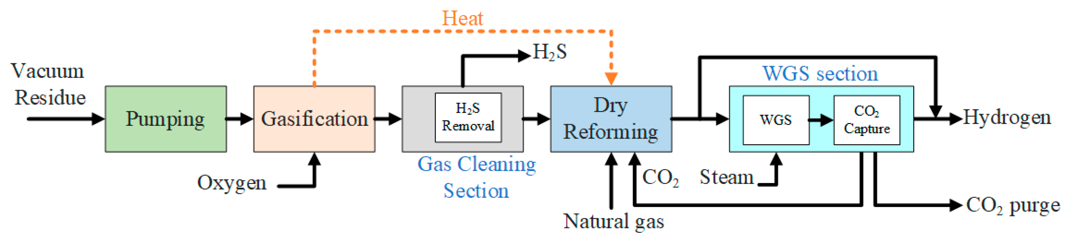
3.1. Case I: Gasification of Heavy Residue in Sequence with DMR

Heavy oil residue is used to produce hydrogen gas (H2). The production process using the series configuration of the equipment is here described. Figure 1 shows the process flow diagram (PFD) for this case. The first section of the process is the gasification process. In the gasification process, the heavy oil residue is gasified in order to produce the slurry. In the gasification unit, the feed materials get cracked and the carbon-based material is converted into syngas. The gasification is a thermochemical process that is carried out at high temperatures, so that all the carbon-based material gets converted to hydrogen gas and CO. After the gasification process, all the carbonaceous material gets converted to syngas [15]. In this process, the heavy oil residue is gasified at 218 °C and 16 bars. The high pressure and temperature of the syngas produced is lowered by the exchange of heat via steam. This steam is then used for power generation through the steam cycle. The steam that is produced here is used in the WGS, which, process-wise, comes after the cleaning unit and the dry methane reforming (DMR) unit. The product stream of the gasifier contains CO, H2, CO2, and H2S. The sulfur contents in the stream can poison the catalyst in the WGS reactor, so it is important to remove the sulfur contents from the stream. The minimum amount of H2S allowed in the WGS unit is 100 ppbv. Subsequently, the product stream is sent to the gas-cleaning unit. In the cleaning unit, the solvent is introduced for the removal of the maximum amount of the sulfur contents in the stream. A conventional absorber–regenerator is used as the gas-cleaning unit. In the gas-cleaning unit, methanol at −34 °C is used to absorb the sulfur compounds and the CO2 gas in the absorber. The product stream is then sent to the CO2-capturing unit, where 95% of the CO2 is removed from the product stream. After the gas-cleaning and CO2-capturing units, the product stream is sent to the dry methane reforming unit. In the dry gas reformer, the methane gas is introduced from the bottom of the reformer. The methane gas and the CO2 gas react and, as a result, CO2 and H2 gases are produced. The reaction in the dry methane reformer is as follows in Equation (4) [14]:
CH4 + CO2 → 2CO + 2H2
The reaction in the dry methane reformer is an endothermic reaction. Dry methane reforming is used when we need a mixture of carbon monoxide and hydrogen. Hence, the product stream contains CO and H2. After this, the pure syngas, which mainly contains CO and H2, is passed through the water–gas shift (WGS) unit. In the WGS unit, the gas stream is passed through the water stream. The water–gas shift reaction is essentially a reaction between CO and water, and CO2 and hydrogen gas are produced as a result. The water–gas shift reaction is as follows in Equation (5):
CO + H2O → CO2 + H2
In the water–gas shift (WGS) reactor, water is introduced in the form of steam, and the water–gas shift reaction takes place. As a result, high-purity hydrogen gas is produced at 24 bars. The WGS reactor emits a purge stream and a CO2 gas stream. The CO2 stream is sent back to the DMR unit as a recycled stream. So concludes the process for hydrogen gas production by the gasification of heavy oil residue in the series configuration.

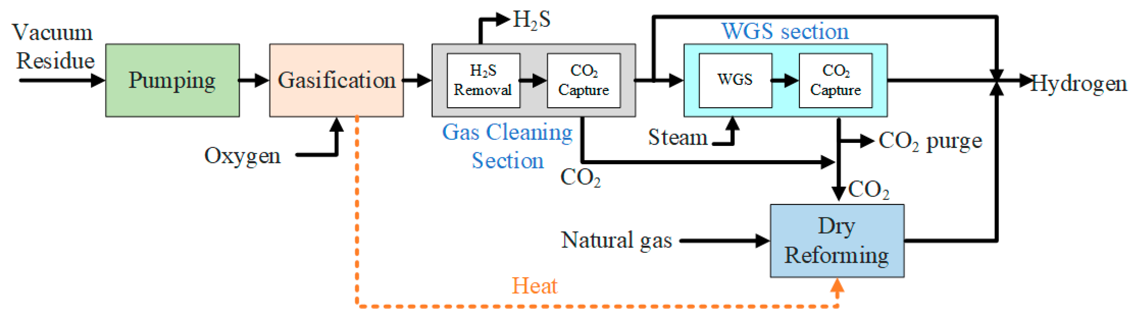
3.2. Case II: Gasification of Heavy Residue in Parallel with DMR

The PFD of hydrogen production using DMR in parallel with the WGS reactor is shown in Figure 2. The hydrogen gas production with this configuration is the same as with the series configuration but with a parallel connection between the dry methane reformer (DMR) unit and the WGS rector. Hence, all the units are the same as those in the series configuration, except for the DMR unit, which is different. In this configuration, the heavy residue oil is sent to the gasification unit and all the carbon-based material is converted to syngas. All the temperature and pressure conditions are similar to the conditions used for the series configuration [16]. After the gasification unit, all the feed material is converted into syngas or undesired products. The CO2 is one such undesired product, and it is removed in the cleaning unit by the CO2-capturing unit [17,18]. After this, the syngas produced is sent to the WGS reactor. The WGS reaction takes place in the reactor, and H2 and CO2 are produced as a result. The CO2 produced in the WGS reactor and the CO2-capturing unit is sent to the DMR. In the DMR, the methane gas is introduced and, as a result of the counter-current interaction between the gases, more H2 and CO gases are produced [17].
Upon comparison of both configurations, it was found that Case II, in which the gasification of the heavy residue oil is done using a DMR unit in parallel, was expected to be more efficient. Later, it will be seen that in the case of the parallel configuration, the conversion of the methane and syngas into hydrogen gas was more efficient and more yield was observed. Thus, as expected, the efficiency of the hydrogen production was improved by using the parallel configuration of the DMR unit with the WGS unit.
On the other hand, there are several limiting factors that can affect the process. For the gasification process, factors such as the temperature, the pressure, and the height of the reactor bed; the fluidization velocity; the gasifying medium; the moisture content of the feed material; the particle size; the equivalence ratio; and the air-to-steam ratio are considered to be limiting factors of the process. In addition, the availability of feedstocks and their properties are limiting factors for syngas production.
However, the operating parameters that influence hydrogen production the most are the temperature at the gasifier, the catalyst used in the DMR, the availability of feedstock, and the properties of the feedstock. The high temperature required by the gasifier is related to the steam requirement and eventually affects the cost.

4. Results and Discussion

The merits and competency of the two designs were evaluated in terms of an energy analysis, their environmental performance, and the economic factors.

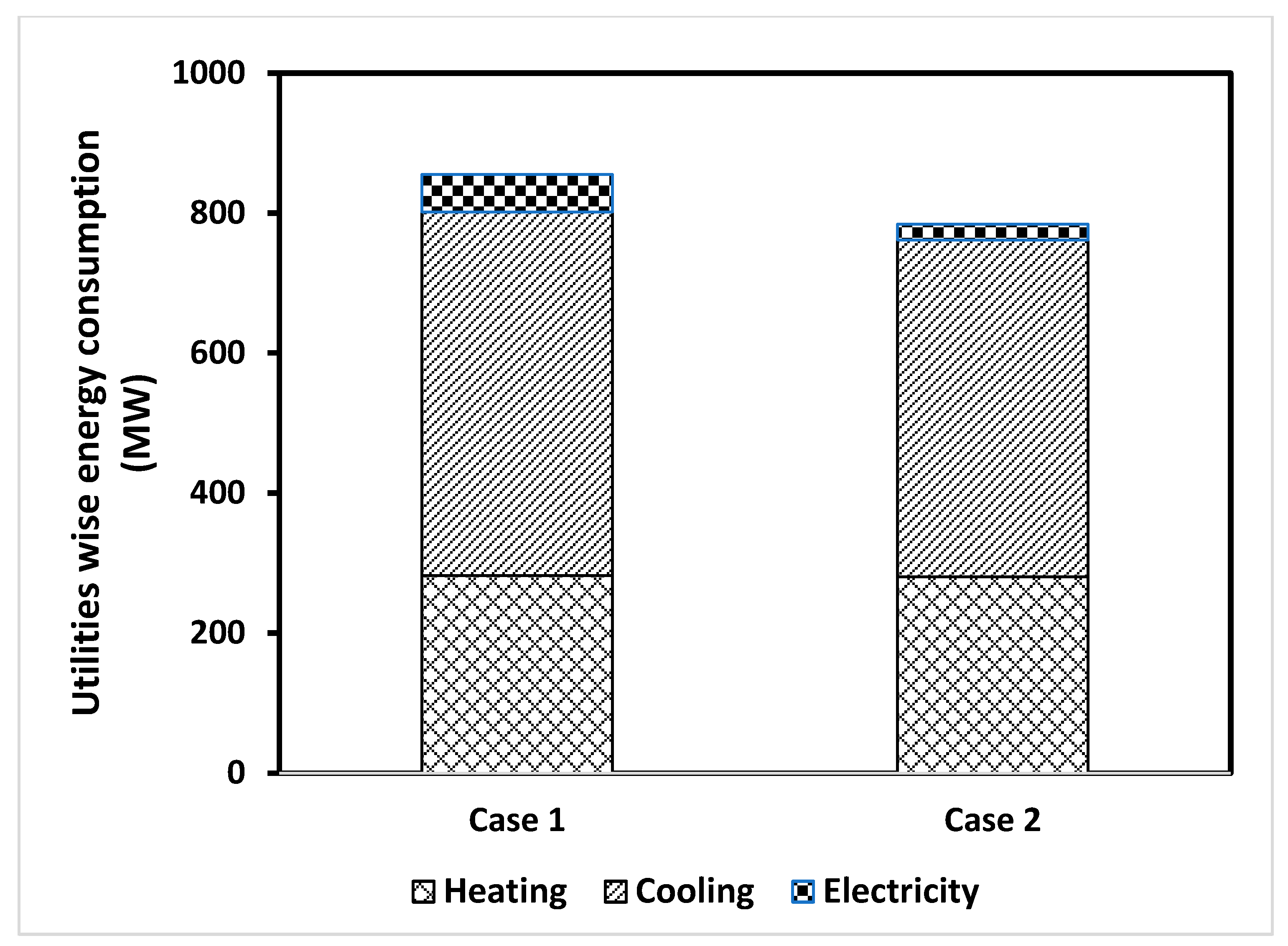
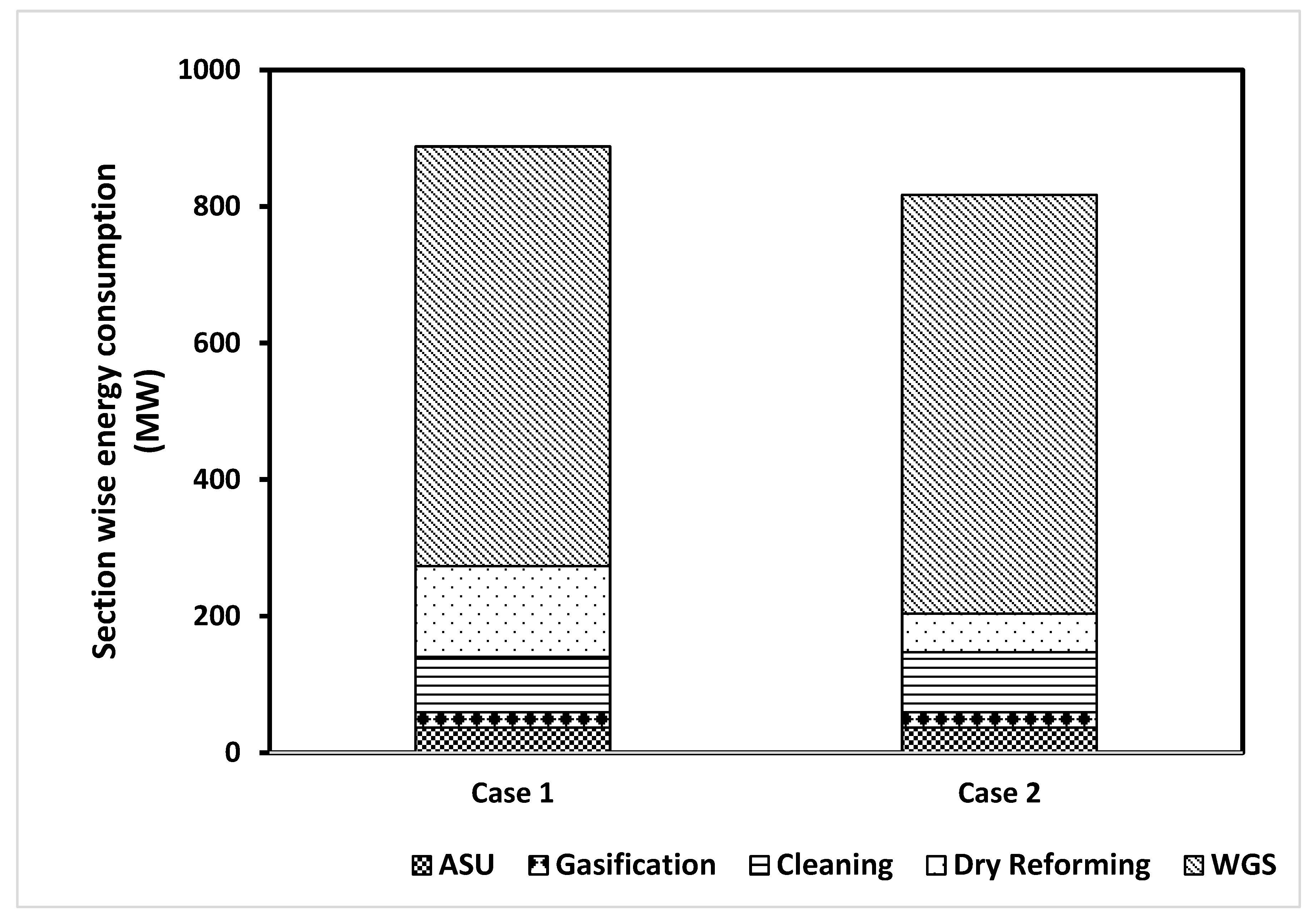
4.1. Energy Analysis

Figure 3 shows the energy consumption in terms of the utilities required for the two designs. The results show that the hydrogen production through the Case I scenario (see Figure 1) required the highest amount of energy, with roughly 50% of the energy demand attributed to the water–gas shift reactions subsystem. The energy consumption for Case II was 817,103 kW, which was less than for Case I by almost 70,000 kW for the same feed rate of heavy crude oil residue. In addition to this advantage of the Case II design, Case II also had a higher energy efficiency (57.8% for Case II and 56.6% for Case I). Moreover, both designs could produce up to 3366 kW of electrical power per the given feed rate of the heavy residue. It was also noticed that that the increase in energy consumption for Case I was due to the greater energy demand from the dry reforming subsystem. This constituted an increase of around 7% in comparison to the energy demand of Case II, due to the cooling utilities in the dry reforming unit, where more cooling power was required. The electricity consumption for Case I was mainly down to the pumps, and the compressors contributed less than 7% of the total energy demand. The heating power demand accounted for around 33% of the total energy for Case I. The cooling power demand was around 61% of the total energy demand, and 75% was consumed in the WGS subsystem, as the reaction conditions required more cooling. For the proposed Case II design (see Figure 2), where the gasification was in parallel with the dry reforming subsystem, it appeared that more than 61% of the total power demand was consumed by the cooling utilities—around 35% of this power was consumed by the heating equipment, and the remaining 3% was electrical power consumed by the pumps and compressors. If we compare the cooling requirement of both designs, we see that Case II required around 9% less cooling power than Case I, which was another advantage in favor of Case II.
When comparing the dry reforming process of both designs, it was notable that the Case I design had an energy demand more than two times, or 230%, greater than that of Case II. Figure 4 shows the energy break-down for the two hydrogen production technologies according to each section of the process.
The results also revealed that the heat energy extracted from the hot syngas could produce 3361 kW of electrical power in both cases.

4.2. Environmental Metrics

The carbon emissions for the two proposed designs were calculated as shown in Table 1. The results showed that the emissions were almost the same for both designs, since all the CO2 captured in the WGS subsystem was eventually converted into hydrogen gas by the WGS. Most of the CO2 emissions came from the WGS section, with more than 37,000 Kg of CO2 released per the given flow rate of the heavy residue processed. This was due to the high energy demand of the stripper and condenser. The specific rate of carbon emission was 0.43 mole of CO2 per mole of hydrogen produced for both designs. The data showed that the two designs were equally favorable in terms of carbon emissions.

4.3. Economic Analysis

The energy analysis performed in the previous section showed that the Case II process consumed around 63 kW less compared to the Case I process for the same rate of hydrogen production (50 t/h). From an economic point of view, Table 1 shows the CAPEX breakdown in terms of the direct and indirect costs. The results show that the direct CAPEX contributed around 65% of costs, while the indirect costs constituted approximately 35% of the total CAPEX. An insight into the CAPEX estimation revealed that the equipment cost was 35% and 38% of the total CAPEX for the Case I and Case II processes, respectively.
The cost of the vacuum residue and natural gas was taken as USD 47.6/bbl and USD 10/1000 ft3, respectively, while the price for the high-purity oxygen was taken as USD 25/t [10]. Table 1 shows the OPEX for the two hydrogen production processes. The results showed that the price of the raw material was the largest factor contributing to the OPEX, followed by the utilities costs. The raw materials and utilities costs constituted 45–47% and 4–7% of the total OPEX, respectively, for the two processes. The results showed that the Case I process required an extra USD 22 million per year than was required by the Case II process for the utilities costs. This was due to the high electricity consumption in the DMR process, which was attributed to the compressor power. The compressors in the Case I process consumed 31 MW more power compared to the Case II. In addition, the heating load in the Case I process was also slightly higher because of the endothermic reactions taking place in the reformer. The results showed that the Case I process required an additional USD 26 million per year of OPEX compared to the Case II process.
Table 1 shows the TAC in terms of the annualized CAPEX and OPEX for the two processes. The results showed that the TAC for Case II was 7% less than for the Case I process. Since the hydrogen production rate was fixed for both designs, the TAC translates into the product costs of USD 17.23 and USD 15.95 per ton of hydrogen produced for the Case I and Case II process, respectively.

5. Conclusions

With a view to limiting the increase in global carbon emissions and enabling the utilization of fossil fuels in a sustainable manner, this study investigated the vacuum-residue-to-hydrogen (VRTH) production process integrated with the dry methane reforming process in two configurations, Case I and Case II, in terms of their energy requirements and their environmental and economic aspects. The proposed VRTH process integrated the dry methane reforming process with the gasification process in two different ways: for Case I, both processes worked in sequence to produce syngas, and for Case II, they worked in parallel to achieve the same purpose. The comprehensive simulation model was based on a hydrogen production rate of 50 t/h with a 99.9 wt.% purity and was developed in Aspen Plus, in order to analyze the performance of the two processes. The major findings of this study are summarized below:
  • The proposed VRTH Case II is a potential process to produce clean fuel such as hydrogen. This process could enable the utilization of the bottom of the oil barrel to convert the oil into a petrochemical that is useful for many applications downstream.
  • The developed Case II VRTH process was competitive and feasible in comparison to the Case I VRTH process. The overall energy requirement of Case II was 8% lower in comparison to the Case I process. The heating load and electricity requirement for the Case II process were roughly 2% and 60% lower, respectively, compared to those of Case I. The results for the Case II process showed that the cost of the hydrogen production per ton of hydrogen was USD 4 lower than for Case I, accounting for millions of dollars per year. Knowing that the price of hydrogen in the market is USD 3–6 per kilogram, this highlights another advantage of the Case II process overall, which clearly demonstrates the process’ viability.
  • The carbon emissions for Case II and Case I were very close to each other, which made both equally favorable in this sense.
  • This study performed a detailed economic analysis, and the results showed that the Case II process required a TAC of USD 349.5 million in comparison to the USD 377.5 million required by the Case I process, offering an annual cost saving of USD 28 million. For a production rate of 50 t/h, this translates to a hydrogen product cost of USD 15.95/t hydrogen for the Case II process in contrast to USD 17.23/t hydrogen for the Case I process. However, the product cost is a strong function of the raw materials cost, which contributes around 45% of the TAC.
  • The profitability of the VRTH process can be further enhanced by integrating it with renewable energy sources. For example, the energy requirements of the ASU and WGS sections of the VRTH process can be omitted with the integration of the VRTH process with a solar-powered water electrolysis process.

Author Contributions

Conceptualization, E.M.A.-M. and U.Z.; methodology, U.Z.; software, S.S.K. and F.N.A.-R.; validation, F.N.A.-R., U.Z. and D.S.A.-Y.; formal analysis, F.N.A.-R.; investigation, A.J.; resources, E.M.A.-M. and A.J.; writing—original draft preparation, F.N.A.-R.; writing—review and editing, U.Z., F.N.A.-R. and E.M.A.-M.; visualization, E.M.A.-M.; supervision, E.M.A.-M. and U.Z.; project administration, A.J. and E.M.A.-M. All authors have read and agreed to the published version of the manuscript.

Funding

This research received no external funding.

Institutional Review Board Statement

Not applicable.

Informed Consent Statement

Not Applicable.

Acknowledgments

The authors would like to acknowledge financial support from King Fahd University of Petroleum and Minerals (KFUPM).

Conflicts of Interest

The authors declare no conflict of interest.

Nomenclature

ACCAnnualized capital charge
ASMEThe American Society of Mechanical Engineers
ASUAir separation unit
CAGRCompound yearly growth rate
CAPEXCapital expenditure
CCUSCarbon Capture, Utilization, and Storage
CTMCoal-to-methanol
EOREnhanced oil recovery
GJGigajoule
IGCCIntegrated gasification combined cycle
IPCCInternational Panel on Climate Change
LHHWLangmuir–Hinshelwood–Hougen–Watson
LHVLower heating value
MWMegawatt
OPEXOperating expenditure
PCAParis Climate Agreement
PRPeng–Robinson
SNStoichiometric number
SRTMSteam-reforming-to-methanol
SRUSulfur recovery unit
TACTotal annual cost
TCITotal capital investment
TRETotal energy requirement
VRVacuum residue
VRTMVacuum-residue-to-methanol
WGSWater–gas shift

References

  1. Omoniyi, O.; Bacquart, T.; Moore, N.; Bartlett, S.; Williams, K.; Goddard, S.; Lipscombe, B.; Murugan, A.; Jones, D. Hydrogen Gas Quality for Gas Network Injection: State of the Art of Three Hydrogen Production Methods. Processes 2021, 9, 1056. [Google Scholar] [CrossRef]
  2. IEA. The Future of Hydrogen: Seizing Today’s Opportunities; IEA: Paris, France, 2019.
  3. Peng, B.; Gao, W.; Motamedi, N. Kinetic modeling of crude oil gasification for hydrogen production with in situ CO2 capture. Pet. Sci. Technol. 2017, 35, 1403–1407. [Google Scholar] [CrossRef]
  4. Khalafalla, S.S.; Zahid, U.; Jameel, A.G.A.; Ahmed, U.; Alenazey, F.S.; Lee, C.-J. Conceptual Design Development of Coal-To-Methanol Process with Carbon Capture and Utilization. Energies 2020, 13, 6421. [Google Scholar] [CrossRef]
  5. Ahmed, U.; Zahid, U.; Onaizi, S.A.; Abdul Jameel, A.G.; Ahmad, N.; Ahmad, N.; AlMohamadi, H. Co-Production of Hydrogen and Methanol Using Fuel Mix Systems: Technical and Economic Assessment. Appl. Sci. 2021, 11, 6577. [Google Scholar] [CrossRef]
  6. Wang, C.; Zhu, C.; Cao, W.; Wei, W.; Jin, H. Catalytic mechanism study on the gasification of depolymerizing slag in supercritical water for hydrogen production. Int. J. Hydrog. Energy 2021, 46, 2917–2926. [Google Scholar] [CrossRef]
  7. Al-Rowaili, F.N.; Khalafalla, S.S.; Al-Yami, D.S.; Jamal, A.; Ahmed, U.; Zahid, U.; Al-Mutairi, E. Techno-economic evaluation of methanol production via gasification of vacuum residue and conventional reforming routes. Chem. Eng. Res. Des. 2021, 177, 365–375. [Google Scholar] [CrossRef]
  8. Akiki, E.; Akiki, D.; Italiano, C.; Vita, A.; Abbas-Ghaleb, R.; Chlala, D.; Ferrante, G.D.; Lagana, M.; Pino, L.; Specchia, S. Production of hydrogen by methane dry reforming: A study on the effect of cerium and lanthanum on Ni/MgAl2O4 catalyst performance. Int. J. Hydrog. Energy 2020, 45, 21392–21408. [Google Scholar] [CrossRef]
  9. Ebrahimi, P.; Kumar, A.; Khraisheh, M. A review of recent advances in water-gas shift catalysis for hydrogen production. Emergent Mater. 2020, 3, 881–917. [Google Scholar] [CrossRef]
  10. Jo, S.B.; Woo, J.H.; Lee, J.H.; Kim, T.Y.; Kang, H.I.; Lee, S.C.; Kim, J.C. CO2 green technologies in CO2 capture and direct utilization processes: Methanation, reverse water-gas shift, and dry reforming of methane. Sustain. Energy Fuels 2020, 4, 5543–5549. [Google Scholar] [CrossRef]
  11. Shamsi, M.; Obaid, A.A.; Farokhi, S.; Bayat, A. A novel process simulation model for hydrogen production via reforming of biomass gasification tar. Int. J. Hydrog. Energy 2021. [Google Scholar] [CrossRef]
  12. Ersöz, A.; DurakÇetin, Y.; Sarıoğlan, A.; Turan, A.Z.; Mert, M.S.; Yüksel, F.; Figen, H.E.; Güldal, N.Ö.; Karaismailoğlu, M.; Baykara, S.Z. Investigation of a novel & integrated simulation model for hydrogen production from lignocellulosic biomass. Int. J. Hydrog. Energy 2018, 43, 1081–1093. [Google Scholar]
  13. Rudra, S.; Tesfagaber, Y.K. Future district heating plant integrated with municipal solid waste (MSW) gasification for hydrogen production. Energy 2019, 180, 881–892. [Google Scholar] [CrossRef]
  14. Ishaq, H.; Dincer, I. Comparative assessment of renewable energy-based hydrogen production methods. Renew. Sustain. Energy Rev. 2021, 135, 110192. [Google Scholar] [CrossRef]
  15. Meramo-Hurtado, S.I.; Puello, P.; Cabarcas, A. Process analysis of hydrogen production via biomass gasification under computer-aided safety and environmental assessments. ACS Omega 2020, 5, 19667–19681. [Google Scholar] [CrossRef] [PubMed]
  16. Ayodele, B.V.; Mustapa, S.I.; Tuan Abdullah, T.A.R. Bin A mini-review on hydrogen-rich syngas production by thermo-catalytic and bioconversion of biomass and its environmental implications. Front. Energy Res. 2019, 7, 118. [Google Scholar] [CrossRef]
  17. Dominko, M.; Lukec, D.; Lukec, I. Optimization of hydrogen production from heavy oil residues. Goriva Maz. 2010, 49, 78. [Google Scholar]
  18. Shahsavan Markadeh, R.; Arabkhalaj, A.; Ghassemi, H.; Ahmadi, P. 4-E analysis of heavy oil-based IGCC. Energy Sources, Part A Recover. Util. Environ. Eff. 2020, 42, 849–863. [Google Scholar] [CrossRef]
Figure 1. Process flow diagram for hydrogen production with DMR in series.
Sustainability 13 13588 g001
Figure 2. Process flow diagram for hydrogen production with DMR in parallel.
Sustainability 13 13588 g002
Figure 3. Total energy consumption in terms of the required utilities.
Sustainability 13 13588 g003
Figure 4. Total energy consumption for Case I and Case II according to each section of the process.
Sustainability 13 13588 g004
Table 1. Results summary in terms of energy and environmental and economic parameters.
Case ICase II
Total energy requirement (MW)888817
Energy efficiency (%)56.657.8
Specific emission (kg CO2/kg MeOH)8.368.70
Direct CAPEX (million USD)75.541.3
Indirect CAPEX (million USD)42.630
OPEX (million USD/y)372.9346.8
Annualized CAPEX (million USD/y)4.62.7
TAC (million USD/y)377.5349.5
Hydrogen (USD/t)17.2315.95
Publisher’s Note: MDPI stays neutral with regard to jurisdictional claims in published maps and institutional affiliations.

