Review

A Review of Numerical Simulation as a Precedence Method for Prediction and Evaluation of Building Ventilation Performance

by
Ardalan Aflaki
1,*,
Masoud Esfandiari
2 and
Saleh Mohammadi
3,4,*
1
School of Architecture and Art, University of Guilan, Rasht 41996-13776, Iran
2
Faculty of Architecture and Urban Planning, Shahid Beheshti University, Tehran 19839-69411, Iran
3
Department of Architectural Engineering & Technology, Faculty of Architecture and the Built Environment, Delft University of Technology, 2628 BL Delft, The Netherlands
4
Research Group Sustainable Building Technology, School of Business Building & Technology, Saxion University of Applied Sciences, 7500 KB Enschede, The Netherlands
*
Authors to whom correspondence should be addressed.
Sustainability 2021, 13(22), 12721; https://doi.org/10.3390/su132212721
Submission received: 29 September 2021 / Revised: 9 November 2021 / Accepted: 10 November 2021 / Published: 17 November 2021
(This article belongs to the Special Issue Optimal Planning of Sustainable Buildings)

Abstract

:
Natural ventilation has been used widely in buildings to deliver a healthy and comfortable indoor environment for occupants. It also reduces the consumption of energy in the built environment and dilutes the concentration of carbon dioxide. Various methods and techniques have been used to evaluate and predict indoor airspeed and patterns in buildings. However, few studies have been implemented to investigate the relevant methods and tools for the evaluation of ventilation performance in indoor and outdoor spaces. The current study aims to review available methods, identifying reliable ones to apply in future research. This study investigates scientific databases and compares the advantages and drawbacks of methods including analytical models, empirical models, zonal models, and CFD models. The findings indicated the computational fluid dynamics (CFD) model is the most relevant method because of cost-effectiveness, informative technique, and proficiency to predict air velocity patterns and ratios in buildings. Finally, widely used CFD codes and tools are compared considering previous studies. It is concluded the application of codes for research is subject to the complexity and characteristics of a studied model, the area and field of study, the desired turbulence model, and the user interface.

1. Introduction

Natural ventilation, as an efficient passive design strategy, has been considered extensively by relevant stakeholders, particularly architects and engineers, in building investments to reduce energy consumption as well as provide a healthy and comfortable indoor environment. A study by Givoni [1] shows that natural ventilation is a widely implemented technique to improve comfort levels for the human body. Increased airspeed over the body enhances sweat evaporation and reduces discomfort due to moistened and wet skin. State of the art on the advantages of natural ventilation application reveals that this sophisticated method brings fresh air into the indoor environment and subsequently dilutes the concentration of carbon dioxide (CO2) to an acceptable level. Thus, an adequate supply of oxygen reduces the risk of “sick building syndrome” (SBS) and improves indoor air quality (IAQ) [2].
Studies that investigated IAQ in different types of residential buildings located in developing countries indicated lower IAQ than the standards suggest [3,4]. Additionally, lowering energy costs for buildings significantly depends on reducing air-conditioning usage over the year. Statistics show that air conditioning represents more than 50% of the annual energy consumption in typical buildings with an electric energy ratio of more than 100 kWh-2 of floor space [5]. Natural ventilation appears to be the preferred choice of ventilation because of cost-effectiveness and better IAQ compared to mechanically ventilated buildings [2]. Kubota et al. [6] indicated applying natural ventilation in the built environment improves thermal comfort in both indoor and outdoor environments, helping to lower energy consumption as well as greenhouse emissions in various climates. Shaeri et al. [7] also highlighted that applying natural ventilation can be useful not only to provide thermally comfortable indoor environments in new constructions but also to improve thermal quality for old buildings. In addition, occupants in naturally ventilated buildings can control the quality of indoor air by opening apertures and windows to remove odours and polluted air [8].
Natural ventilation does not require additional sources of energy to replenish indoor air with fresh outdoor air. Thus, it is more economical compared to mechanical ventilation in buildings. However, various parameters influence the quality and quantity of natural ventilation, resulting in a more complex control process compared to mechanical ventilation [9]. Several design alternatives have been investigated and discussed in previous studies to identify an efficient ventilation method in the built environment. In [10,11], the dimension and configuration of air inlets and outlets throughout buildings have been investigated. The findings indicated characteristics of openings can change flow stream behaviour inside the building, which allows designers to control the recirculation zones. Badas et al. [12] studied architectural elements influencing the direction of wind flow. This study indicated that gable roofs in the building façade can significantly change the flow regimes in urban canyons. As a result, pitch ranging from 0° up to 40° plays a key role in increasing turbulence and enhancing ventilation. Surrounding buildings can also impact natural ventilation performance. In [13], a challenging effect caused by surrounding buildings was approved by the wind tunnel experimental tests. Moreover, the airflow pattern and speed inside the buildings are influenced according to wind angles. Transom ventilation panels (TVPs) are another architectural feature that is generally applied in compact buildings to improve natural ventilation performance. A study on the effect of TVPs on ventilation performance of a unit in a high-rise building in a tropical climate confirmed that this element can increase indoor air velocity up to four times, depending on the outdoor wind speed and location of the unit within the residential block [14]. Along with studies on architectural features and elements to enhance ventilation inside buildings, research on urban features and their impact on wind speed and pattern were carried out. Large-eddy simulations and wind tunnel experiments were established in a study to understand the effect of roof types on the mean wind flow in street canyons. The results showed that the form of the building roof plays a significant role in the airflow and turbulence statistics of the urban street canyon. Moreover, pitched and round roof geometries increase in-canyon mean and turbulent velocities [15]. In a study using the computational fluid dynamics (CFD) model for the wind behaviour on a large scale, it was found that the airspeed at the open spaces and alley entrances and exits was higher than at other locations in a neighbourhood due to higher pressure, especially at the windward sides near the sea [16]. A study using CFD analysis [17] confirmed that urban block height and widths of adjunct roads can impact the removal of air pollutants by natural ventilation.
Previous studies have investigated and reviewed the state of the art in the application of natural ventilation [18,19,20,21,22]. However, there is a need to study methods and techniques for the evaluation and prediction of airflow inside and outside buildings. In another words, quantifying the ways the above-noted parameters impact natural ventilation in various types of buildings has rarely been considered in previous studies. For instance, a study by Omrani et al. [23] focused on applicable methods only for multi-story buildings. Moreover, methods using zonal and multi-zonal models, especially for evaluation of ventilation performance in large-scale buildings, have not been studied. Although Chen [24] investigated an extensive range of methods to support CFD simulation as the most applicable technique, considerable effort should be made to identify accurate and reliable models. Few studies have been carried out in the recent decade to review the efficiency of models like building energy simulation (BES)-CFD coupling and CFD-network models along with other techniques.
Understanding relevant methods for the evaluation of airflow helps the designer to examine the best alternative designs for effective ventilation. The techniques for the prediction of indoor and outdoor airflow patterns and speed provide additional knowledge on the application of architectural elements, especially in the building’s façade, for ventilation improvement. The results of these studies can help to model a building to understand the optimized passive design strategies for maximum ventilation before construction as well as the bio-climatic adaptation of buildings. Although this area of research plays an important role in the field of ventilation strategies in the built environment, few studies have been implemented to understand the suitable methods and techniques. This study reviews methods and tools for the evaluation and prediction of airflow in outdoor and indoor environments. In addition, this study compares various evaluation and prediction methods to identify effective alternatives and reliable methods for future research. In detail, this study investigates recently developed knowledge in each method to prepare a platform for researchers in selecting proper tools for studies to focus on applying natural ventilation in the built environment. After diagnosing the most applicable and reliable method, the study goes further to discover the available software for further investigation in natural ventilation.

2. Methods and Techniques

This study delivers a state-of-the-art review of the recent investigations applying methods and techniques to evaluate ventilation performance in a built environment. The materials have been selected through peer-reviewed journal articles, dissertations, and analyses of published scientific literature related to the assessment of airflow patterns and speed. Some manuscripts contain field studies and cross-sectional multi-building investigations of ventilation to promote thermal comfort or indoor air quality as well as structural cooling in buildings. These studies collected data on the environmental conditions and air change per hour inside buildings, whereas some other studies collected reliable source information from scientific databases to achieve the goal of study.
This study applied a structural approach to determine and identify the reliable materials for this review. The peer-reviewed literature was the main source of information and data. To achieve the goal, searches through scientific databases such as ScienceDirect, MDPI, Springer, Google Scholar, etc., were limited to studies with methods, techniques, and tools applied to evaluate wind speed and patterns inside and outside of a building. Key criteria were used in the decision tree for selecting articles in the literature review. The criteria consisted of databases that contained selected keywords, including analytical model, empirical model, multi-zone model, and CFD model. Each keyword had sub-categories of main words for further investigation. All research studies were managed in a reference manager program in different groups. Once abstracts had been identified as relevant to the criteria and worthy of further exploration, the full article was retrieved. The articles were skimmed, after which a further selection was made based on criteria including the terms discussed in the literature review outline. Finally, all results were classified for further analysis. The analysis was carried out by comparison of methods according to the advantages and disadvantages, range of application, validity, and reliability. After the selection of the appropriate method, an advanced search was carried out to identify and suggest suitable software to do the CDF models based on the criteria derived from the literature.

2.1. Analytical Models

Fundamental equations of heat transfer and fluid dynamics are applied in analytical models to predict ventilation and heat transfer in buildings. As the oldest methods for ventilation performance forecast, analytical models are applied broadly due to their reliability and simplicity in the physical space. Furthermore, the widespread use of these methods is related to the minimal requirements in computing resources, regardless of whether such models might be inaccurate when predicting complicated ventilation scenarios and the results obtained might be uninformative. These models are regarded as the most dominant tools for predicting ventilation performance. This is because they produce both qualitative and quantitative (occasionally) indications of the effect on different geometries and thermo-fluid boundary conditions imposed on ventilation performance [24]. Table 1 summarizes studies that investigated natural ventilation using an analytical model.

2.2. Empirical Models

The empirical models are derived from the conservation equations, such as the mass, energy, and chemical species equations. In theory, there is little difference between analytical and empirical models but the perception is that empirical models use more approximation than analytical models [24]. Therefore, in some cases, researchers combine analytical and empirical models for the analysis of wind velocity [30]. However, comparing their application in previous studies shows that the empirical models are efficacious, cost-effective, and allow designers to predict the performance of ventilation in building construction sectors [24].

Experimental Models; Small and Full Scale

Experimental models are usually used as the preferred method for predicting ventilation in buildings. In practice, the application of small-scale experimental models can be more cost-effective than full-scale experiments. Although small-scale experimental models are efficient and economical for ventilation performance investigation in buildings, it is difficult to represent the airflow in the same manner as in an actual full-scale experiment in the event heat transfer is considered in the calculation. This is due to the difficulty in getting the same Reynolds and Grashof numbers [24]. If the objective is simulating thermal buoyancy, then it is possible to use liquids like water with different densities. If this is not the case, the small-scale model cannot accurately simulate the actual flow in the building. Small-scale models are largely applied to validate the analytical, empirical, or numerical models of ventilation performance. Therefore, the researcher can scale up the validated models for further analysis and design parameters. Table 2 presents some of the recent studies that investigated the application of natural ventilation using experimental models.
Full-scale experimental models can be categorized into two techniques as laboratory experiments and on-site measurements. Laboratory experiments use the application of an environmental chamber to simulate a single-story building. The chamber can then be placed in a wind tunnel for measurement. However, this process increases the cost; therefore, it is considered to be an expensive research method [38]. Although the cost is higher in this method, many researchers have applied laboratory experiments to forecast wind-induced ventilation inside buildings up to present day [39,40].
On the contrary, full-scale measurement models are normally designed on real buildings based on the meteorological conditions of the site. This technique depends mostly on the real boundary conditions of the site such as surrounding landscape, buildings, and terrain that have a direct impact on outdoor wind direction and magnitude. On-site measurement is quite familiar to researchers, and it is used to identify the real conditions of ventilation inside and outside a building [41,42,43]. According to Chen [24], both laboratory and on-site measurements for full-scale experimental models represent realistic predictions of a building’s ventilation performance.
There are some limitations to the application of full-scale measurement in buildings. The data collected from one building cannot be applied to another building even though both buildings are similar. It should be considered that errors can happen in experimental measurements due to uncalibrated measuring equipment [44]. For instance, in conditions with very low air velocity, hot-wire anemometers have difficulties providing accurate values for the ratio of air velocity. Although the full-scale models are expensive and time-consuming, they are substantially used to validate computational models like CFD. This is because CFD models are based on prediction. As Chen [24] indicated, these methods are widely applied to evaluate ventilation through buildings.

2.3. Multi-Zone and Zonal Models

The multi-zone model was applied in previous research to predict airflow distribution and air exchange rates in buildings with and without mechanical ventilation systems. The model can evaluate ventilation efficiency, energy demand, and pollutant transport. It is widely used as a design tool for computing airflow in large buildings. Multi-zone models are normally run by two well-known programs developed in two national laboratories in the United States called CONTAM and COMIS [45]. Few studies have used these programs to determine the air quality and the magnitude of air velocity inside buildings [46,47]. However, the application of multi-zone models through CONTAM and COMIS is scarce in research work due to difficulties working with the user interface and data input [24].
The assumption in multi-zone models is that they are unable to predict stratified ventilation systems; therefore, to reduce errors in predicting air temperature distribution, zonal models are applied to allocate a space into limited cells. These cells are normally less than one thousand for a three-dimensional space. Moreover, the air temperature is predicted in each cell to specify a non-uniform distribution in the space. In most cases, zonal models are integrated with other models to predict indoor air temperature, pollutant concentrations, and the cooling and heating loads of HVAC systems [48].
The zonal model simulation’s accuracy declines significantly when the momentum of the flow is strong. This is due to the model’s inability to solve the momentum equation while it is occupied with the mass and energy balance equations to reduce computation cost. Furthermore, the zonal models do not represent more control in reducing the computational time when compared to very coarse-grid fluid dynamic simulations [24]. The overhead time to prepare the input data in most cases is lengthier than that of a CFD simulation. A future projection is that zonal models should be substituted with CFD models because computers are getting quicker and the CFD interface will be more user-friendly.

2.4. Computational Fluid Dynamic (CFD) Models

The numerical simulation of CFD in predicting air velocity is commonly used in the design of ventilation systems in the construction sector. CFD solves several partial differential equations for conservation of mass, momentum (Reynolds Average Navier–Stokes), and energy [24]. Furthermore, the CFD models are established extensively to evaluate indoor air temperature, pressure, air velocity and its pattern, thermal comfort, contaminant concentrations, and turbulence quantities in specific computational domains for both indoor and outdoor spaces of buildings. The parametric study has full control over boundary conditions in CFD, which allows the evaluation of different design alternatives. Thus, the optimum design can be determined to enhance maximum ventilation inside a building. Table 3 presents recent studies that implemented CFD to investigate natural ventilation.
The advantage of CFD is that it covers heat transfer from surfaces such as convection and transient behaviour [49]. The improvements in computing capabilities and user-friendliness of its graphic user interface make CFD the popular method for predicting wind-induced ventilation inside or outside buildings. The Reynolds Averaged Navier–Stokes equation (RANS) model and the Large Eddy Simulation (LES) are normally included in the CFD models.

3. Arrangement of Experimental Models and CFD Models for Natural Ventilation (NV) Evaluation and Prediction

Recent research in the field of natural ventilation in buildings argue that full-scale measurement and computational fluid dynamic models (CFD) are two sophisticated methods that represent precise details and information in the studying of wind-driven ventilation in buildings [58,59,60]. Full-scale measurement can be employed to determine primary thermal conditions such as the magnitude of air velocity or the value for indoor temperature. The results of full-scale measurement can be used for CFD model validation. Thus, the validated CFD models allow for the evaluation of further design alternatives that are impossible to test with full-scale measurement. CFD model application for natural ventilation designs has become more predominant. There is a growing need for the use of natural ventilation to reduce energy demand and enhance IAQ [61]. A comparison of CFD models with other techniques reveals that it can predict air velocity patterns and ratios in buildings. For instance, multi-zone models cannot overcome some complex scenarios for natural ventilation such as its variability in speed and direction [24]. A study by [62] shows that CFD models can simulate small-scale to large-scale buildings such as stadiums and skyscrapers. It can also predict thermal parameters like air temperature and wind velocity in indoor and outdoor environments. Previous studies confirm that the results of primary techniques like a wind tunnel or experimental testing can be substituted with CFD results because they are in good agreement [63,64]. The CFD model is more informative and cost-effective compared to wind tunnel tests and full-scale experimental methods [65]. Furthermore, CFD models can be integrated with other building simulation tools like energy simulation to present wider ranges of precise predictions. Generally, there are two approaches in CFD modelling: internal flow simulation and combined internal and external flow simulation known as the “coupling” approach. Study [66] states that for internal flow simulation, boundary conditions at inlets and outlets, which may be obtained from wind pressure data for openings, are required. In the “coupling” approach of flow simulation, climate data and wind profiles are required as the atmospheric boundary layer.

4. CFD Coupling Building Energy Simulation

Reducing the energy consumption of buildings has become a worldwide challenge. Particularly, this becomes highlighted designing net-zero energy buildings, which require new design strategies. Although several approaches and a variety of studies are discussed in the literature to simulate building energy performance, building energy simulation (BES) coupling CFD has earned more attention [67,68]. This idea was first introduced by Negrao [69], who indicated the need for both BES and CFD to exchange appropriate boundary conditions. Subsequently, Zhai et al. [70] reviewed the state of the art to classify the coupling models according to their interaction and data exchange between the tools. The coupling idea was expanded by Zhai et al. [71], who verified existence, uniqueness, and convergence of the results obtained according to thermal aspects, and Wang et al. [72], who included airflow exchange variables into the coupling model. Since then, the coupling idea has been implemented to investigate various aspects of the indoor environment such as Wang [73] to study airflow and contaminant spreading, or, on a larger scale, Bouyer et al. [74] developed a CFD–thermo-radiative coupled simulation to investigate the microclimatic impact on building energy performance. Zhang et al. [75] developed a coupling model to investigate convective heat transfer in various urban areas. More recently, a coupling framework method was developed by Pandey et al. [76] between BES and CFD to model phase change materials (PCM) integrated in a built environment in three different scenarios: the active use of PMC and the passive use of PMC during natural and forced convection. This study also compared the prediction of this coupling method with BES tools results such as EnergyPlus and concluded prediction is more accurate when applying the coupling method [76].

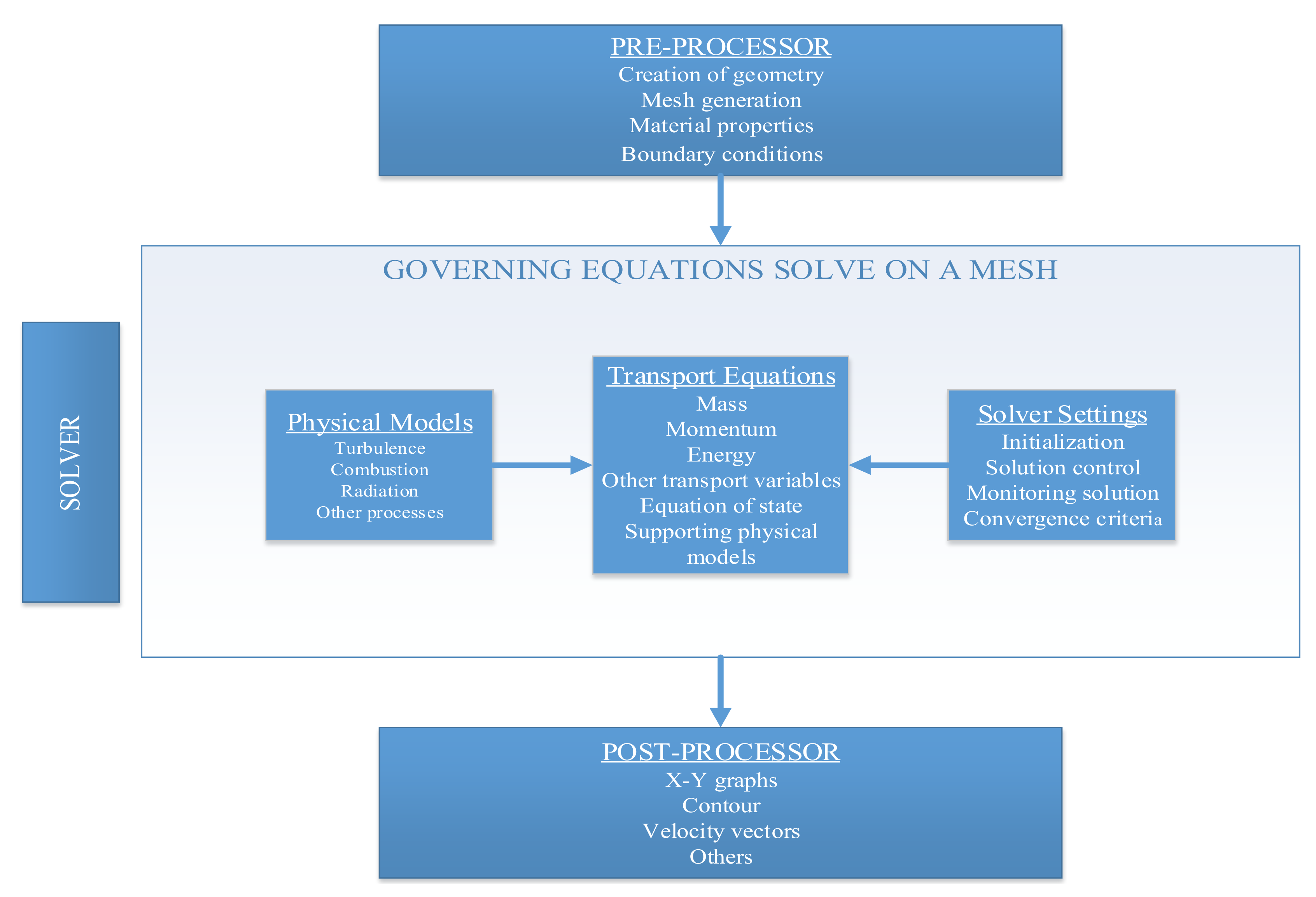
5. CFD Fundamental Frameworks

The CFD technique combines theoretical and experimental science with the power of modern numerical computation. In theory, CFD can solve issues like steady and unsteady flows, turbulent and laminar flows with and without considering heat transfer, flows combined with radiation, compressible and incompressible flows, and other more complex flows. CFD solutions are defined as technical numerical estimates of fluid flow by governing equations within space and time. Generally, a CFD code works by defining interest regions based on many cells and grids. The fluid flow is explained by the partial differential Navier–Stokes equations in CFD. These equations are substituted in each of the cells by algebraic approximations that attribute some variables, such as air velocity and air temperature, to the values in the adjacent cells. Once these equations are solved numerically, they create a comprehensive airflow profile for the grid resolution. According to a study by Tu et al. [58], the CFD codes include three main elements: the pre-processor, the solver, and the post-processor.
The general framework and interconnectivity functions of these elements in the CFD analysis are presented in Figure 1. At the pre-processor stage, the computational domain is created for the finalisation of the geometry of the model. A finite number of cells is generated sophisticatedly at this stage to the solution domain. Subsequently, the boundary conditions specification and fluid properties are set up. At the solver stage, the numerical solver resolves the equation of each state until a satisfactory convergence is achieved. Simultaneously, five numerical solution methods are finalised in line with the way the flow variables are predicted in the discretisation process. The numerical simulation techniques are the finite difference method, the finite element method, the finite volume method, the spectral method, and the girdles method. In principle, provided that the grid is very fine, each method would consequently generate the same solution.
The post-processing stage is defined as the last stage where the modelled results are presented numerically and graphically. The results are visualised in different ways using 2D graphs, 3D representations of the vectors, iso-lines, and flow tractions [59]. Generally, the CFD simulation is applied for both compressible and incompressible flow for either external or internal flow or their combination, called the coupled flow method. The coupled flow method shows a comprehensive picture of inside and outside the building. It is particularly used for the simulation of wind-driven ventilation in buildings. Heat transfer via conduction, convection, and radiation can influence airflow patterns and ratio. Thus, heat transfer equations are established in CFD programs to address the above-noted effect. Figure 2 shows a schematic framework of CFD through the various heat transfer option and flow physics.

6. CFD Application through Physical Models

There are three major governing equations of computational fluid dynamics, namely. the continuity, momentum, and energy equations. According to Yang [59], these equations are the mathematical statements of three basic physical principles referred to below:
  • Conservation of mass (the continuity equation);
  • Newtons’ second law (the momentum equation);
  • Conservation of energy (the first thermodynamic law).
These fundamental equations are the basis for various simulation approaches. Turbulence models for statistically steady simulation are the main focus of this section as they are required to parameterize the unresolved scales related to the flow. The forces on the fluid control volume concerning the fluid acceleration create an expression for the conservation of momentum, done by employing Newton’s Second Law of Motion (or Navier–Stokes equations). The Navier–Stokes equations are stated as valid to explain the turbulent flows. In wind engineering, the Reynolds Average Navier–Stokes (RANS) approach can be considered the preferred method for turbulent flow computation. To make a statistically steady solution related to the flow characteristic, the equations are typically averaged in time over all the turbulent scales in this approach [60]. According to the First Law of Thermodynamics, energy is conserved in a fluid. Furthermore, the rate of change of the fluid particle energy is equal to the sum of the net rate of work done on the fluid particle, the net rate of the heat added to the fluid, and the rate of increase in the energy due to the sources [61]. Thus, defining the changes in the fluid temperature is allowed within a control volume.

6.1. Turbulence Models

Turbulent flows are generated by fluctuating velocity fields that have small-scale but high-frequency movement. Thus, it seems impossible to model this fluctuation by available computers. In this case, for extracting the small fluctuations, the fluid mechanics equations should be averaged by the application of a transformed group of equations that will be solved numerically [77]. The modified equations contain added variables that need to be resolved through a turbulence model. In this context, the turbulence models are categorized into three major groups called the direct numerical simulation (DNS), the large-eddy simulations (LES), and the Reynolds Averaged Navier–Stokes (RANS). These groups are briefly explained below.
Direct numerical simulation (DNS) is a computational fluid dynamics simulation whereas the Navier–Stokes equations are resolved numerically without the use of the turbulence model. This implies that the variety of temporal and spatial scales of the turbulence must be resolved. Consequently, the DNS computational cost is considerably high and the computational resources required by a DNS will exceed the capacity of the most powerful computer, at the low Reynolds numbers.
Large eddy simulation (LES) models are approaches that are time-dependent and can generate results with greater accuracy, taking into consideration the numerical simulation of the wind engineering problems, as compared to the statistically steady RANS simulation [78]. In a study by Evola et al. [79], it was shown that LES is based on space filtering the turbulence structures. This is where the fluid flow is divided into small and large eddies. Although the LES model has greater reliability, it is time consuming due to the requirement for more complex computations. This occurs because of the extreme precision required. As opposed to the standard RANS type models, the LES reproduces the central turbulence properties with greater accuracy. It should however be noted that the LES applications are still experimental. Therefore, choosing realistic boundary conditions will be problematic for such simulations [77]. Furthermore, LES methods need large computing power an impose greater CPU times. They also have very tight mesh alongside a very long calculation time. In practice, these methods are impractical for application in engineering for the near future [60]. For this reason, the LES model is a less popular option and is very rarely used for wind-driven ventilation studies.
Researchers have claimed that the RANS equation turbulence model is a widely used method for wind-induced ventilation that requires much less computing time as compared to other turbulence models such as the LES turbulence model [49,80]. The Reynolds stress comprises all the effects due to the turbulence fluctuation when it makes use of the eddy viscosity hypothesis (first order closure) and the Reynolds stress model (RSM) or second moment closure (SMC) in RANS models. Zero, one, two, three, and four equation models are contained in the eddy viscosity models. Among these models, the two-equation models, which entail k-ω and k-ε models, are the commonest models used for the application of natural ventilation [81,82,83,84]. The most well-known equation models in the applications of wind-driven natural ventilation are the standard k-ε model and the RNG k-ε model as the subgroup of the k-ε model and the standard k-ω model and the shear-stress transport (SST) k-ω as the subgroup of the k-ω model.

6.2. Reynolds Average Navier–Stokes (RANS) Turbulence Models

Viscous transport was introduced into the Euler equations by Claude Louis Marie Henry Navier and George Gabriel Stokes, which resulted in the Navier–Stokes equations. This is the basis of CFD models until now [85]. In 1883, Osborne Reynolds developed the “Reynold Number”. He also established the RANS model theoretical basis where turbulent equations are averaged out by the models, in time, over the whole turbulent fluctuation spectrum [86].
Essentially, the Reynolds Average Navier–Stokes (RANS) model solves a set of transport conservation equations for continuity, momentum, energy, and chemical species concentrations [66].

6.3. Eddy Viscosity Equation Models

6.3.1. The k-ε Model

The k-epsilon model is the most noticeable and preferred model for turbulence that is employed in the CWE extensively, and it is still known as the standard industrial model [87]. The k-ε turbulence model is that in which the transport equations for “k” are the kinetic energy turbulence and “ε” is the dissipation rate. The model is the most recognized by experiment and widely used due to its robustness and accuracy [88,89]. Awbi [66] stated that the k-ε model is used mostly for the turbulence model, which can forecast reliable results for studies on airflow in the built environment. The k-epsilon model is numerically robust and stable, has a regime that is well-recognized, and has a capability that is predictive for the general-purpose simulations regarding their robustness and accuracy [90].
The k-ε standard model was used and the results revealed small variations among the different turbulence models. The Mono draught wind catcher ABS 550 performance was assessed by the k-ε standard turbulence model. It was found that the prediction accuracy made by the k-ε standard model was adequate in simulating ventilation in buildings [91]. The multi-directional wind catcher’s performance was evaluated by Montazeri [92] through the application of the k-ε standard turbulence model in the CFD simulation. Many surveys confirm that making use of the k-ε turbulence model is well-recognized in the natural ventilation survey field [93]. In the application of wind engineering, this model can yield acceptable results [94].
A major issue known with this model is its ability to over-predict the turbulence kinetic energy in parts that have stagnant flow. Therefore, k-ε models that are more advanced are employed progressively. An illustration of such a model is the renormalization group (RNG) k-ε model [95]. The RNG k-ε model is an alternative to the k-ε standard model. Comparing it with the k-ε standard model, as a whole, the model provides a small enhancement anomaly in the attenuation of stagnation points and yields acceptable results afterwards [96]. This model has an effect in predicting turbulent motion that is small-scale because of the large scale turbulent and viscosity modification. This is also because a low Reynold number produces small-scale turbulence. Mathematical theory is used to divide the RNG k-ε model constants including the addition of the term in the dissipation equation related to the turbulent viscosity and the total rate of strain [88].
Blocken et al. [96] attempted to solve the 3D RANS equations in conjunction with the RNG k-ε turbulence model for analysing the conditions of flow in a Venturi-shaped roof while there was an under-pressure concentration in the narrowest roof section. In the above-noted research, the RNG k-ε turbulence model was chosen for its good performance surface pressures prediction on the windward building’s facades and in the roof opening in a preliminary study.

6.3.2. The k-ω Model

The flow separation of the precise prediction from a smooth surface has been reported as a major turbulence modelling issue. The two standard turbulence model equations are unable to predict the onset and the quantity of the separation of flow under adverse pressure gradient conditions. In many technical applications for external and internal flows, separation forecasting seems to be important. Today, the most evident two-equation models in the field are the k-ω based models described by Menter [97]. The k- ω based shear-stress-transport (SST) model was established to provide very accurate forecasts of the onset and the flow separation quantity under adverse pressure gradients.

6.3.3. The Reynolds Stress Model

The two-equation turbulence models (k-ω and k-ε based models) can yield suitable predictions of the properties and physics of many flows of industrial relevance.
Due to the included transport equations, this method needs greater computational resources. It further needs to provide only good iterative convergence in the case where fine grids of good quality are used. Although the flow results around the obstacles are better compared to the ones from the linear eddy viscosity models [98], several models also have issues in the stagnant flow regions, making them unable to experimentally predict the reattachment observed on the top of the building models [78,99]. The RSM (Reynolds-stress model) methods were developed to provide improved results, compared to their predecessors, of various complexities related to flow around buildings, which include stagnation areas, strong pressure gradients, separation flow, very curved movements, and the like [77]. Table 4 summarises RANS turbulence models and their applications in fluid mechanics. By considering the reviewed literature related to the turbulence models, the overall conclusion is that the k-ε model is considered as the most noticeable and preferred turbulence model for predicting wind-induced ventilation.

7. Numerical Discretization Methods

Discretisation methods are used to solve the Navier–Stokes equations. Generally, these methods are categorised into three separate methods: the finite difference method (FDM), the finite element method (FEM), and the finite volume method (FVM).
As claimed by Awbi (2003), the FVM is the most popular for solving the Navier–Stokes equations in ventilation studies. FDM is the oldest method developed by Euler in 1786 to obtain numerical solutions of differential equations [58]. However, this method is rarely used due to its limitation of geometrics [100]. In contrast, the FEM solves the partial differential equations over smaller finite control volumes. The FEM is the foundation of understanding the fundamental features of discretisation [58]. Furthermore, the FEM is the most robust of all methods with which the residual equation is weighted and integrated over the domain.
Although the FEM is more stable than FVM, it requires more computing than FVM [101]. FVM is the most popular method and is widely applied in almost all commercial CFD codes. The FVM discretises the integral form of the conservation equations in the physical spaces directly. Moreover, it works with control volumes that can accommodate any grid type. An advantage of FVM is its flexibility with both structured and unstructured grids. The FVM method allows the discretisation of complex physical domains in a simpler way rather than the transformation of equations to generalise coordinates in the computational domain.

8. Comparison of Simulation Tools

As discussed, CFD commercial codes use coupled and de-coupled approaches to predict a building’s ventilation performance. Whereas the coupled approach simulates indoor and outdoor spaces at the same time, the de-coupled approach simulates outdoor and indoor domains separately. In the de-coupled simulation, the output data gained from the outdoor airflow simulation are used for the boundary conditions of indoor airflow simulation. There is some CFD commercial software that investigates the ventilation performance of buildings. General consideration should be considered when choosing appropriate CFD software. The main criteria for the selection of the software are:
  • Cost;
  • Serviced support and availability;
  • User-friendly software for modelling and simulation;
  • Graphical user interface availability;
  • Discretization methods;
  • Turbulence models;
  • Type of mesh generation.
Many studies have attempted to make a comparison between the advantages and disadvantages of different CFD codes. Considering the above-noted criteria, Table 5 shows the comparisons among five commercial CFD programs. According to the criteria, the selected CFD codes are the most suitable alternatives to establish CFD simulation. However, the selection of these codes for a study depends on the complexity and characteristic of the model, the area and field of study, desired turbulence model for a study, and ease of use for the graphic user interface.

9. Conclusions

This study reviewed methods and techniques for the evaluation and prediction of wind ratio and patterns in the built environments. Based on the methods applied in previous studies, this study found analytical models, empirical models, zonal models, and CFD models to be the available methods. Although analytical models have been rarely applied in previous studies, they can offer quantitative and qualitative indicators to generally understand wind speed and patterns in buildings. Further research should be implemented to identify why analytical models are not favoured by researchers as well as the possibility of integration with other methods to generate more accurate results. Empirical models use more approximation than analytical models; however, they were used widely due to efficiency and cost. However, there are some restrictions for the applications, such as the need for frequent calibration of equipment, possible errors during measurement, large time consumption, and less opportunity to generalize the results. Therefore, in most cases, integration with other methods is highly recommended for future research. Zonal models are suggested in the case of large-scale buildings where techniques like analytical and empirical models cannot work efficiently. Yet, the literature review indicated few studies applied this method due to the absence of a graphical user interface or user-friendly programs. Furthermore, the multi-zonal model can not predict stratified ventilation systems and they should be substituted with zonal models. This study recommends avoiding applying zonal models due to the limitation of cells for the three-dimensional spaces.
A comparison among the reviewed methods indicates the CFD models are predominately applied in existing studies. As an informative method, it offers a parametric study for the evaluation of different design scenarios in a short time. Its compatibility with empirical methods delivers the possibility for substitution of results in the case of complicated models. In addition, the CFD models can be combined with other building simulation tools such as BES to present a wider range of precise predictions. In addition, the improvements in computing capabilities and user-friendliness of the graphic user interface make CFD a popular method for predicting wind-induced ventilation inside or outside buildings.
Among the turbulence models for CFD simulation, this study concluded that the RANS equation turbulence model is the most relevant and it requires much less computing time. A comparison between turbulence models confirmed further studies need to be conducted to suggest procedures for the increase in practicability of LES models for use of simulation in building scale. This can be more important in the case of analysis of ventilation performance in buildings for long periods. The RANS model is widely used in studies; however, this study focused on the standard k-ε model and the RNG k-ε model, particularly, the standard k-ω model and the shear-stress transport (SST) k-ω as the subgroup of the k-ω model for the numerical simulation. Among the models, it is concluded the k-ε is the widely applied method to evaluate indoor airspeed and patterns in the built environment. This study found that there is a need for further research on the weaknesses of a k-ε model compared to other models in buildings.
Finally, this study compared available CFD codes based on ease of use, availability of graphic user interface, turbulence models, discretization method, and type of mesh. Based on the review of studies that applied the CFD model, it is found that the selection of CFD code highly depends on the complexity and characteristics of the model, ease of use for graphic user interface, and the desired turbulence model. Although the data are derived from the academic databases, future studies should consider the users’ point of view.

Author Contributions

Conceptualization, A.A. and M.E.; methodology, A.A.; writing—original draft preparation, A.A.; writing—review and editing, M.E. and S.M.; visualization, S.M. All authors have read and agreed to the published version of the manuscript.

Funding

This research received no external funding.

Institutional Review Board Statement

Not applicable.

Informed Consent Statement

Not applicable.

Data Availability Statement

The data presented in this study are available on request from the corresponding authors. The data are not publicly available due to confidentiality.

Conflicts of Interest

The authors declare no conflict of interest. The funders had no role in the design of the study; in the collection, analyses, or interpretation of data; in the writing of the manuscript, or in the decision to publish the results.

References

  1. Givoni, B. Indoor temperature reduction by passive cooling systems. Sol. Energy 2011, 85, 1692–1726. [Google Scholar] [CrossRef]
  2. Santamouris, M.; Allard, F. Natural Ventilation in Buildings: A Design Handbook; Earthscan: London, UK, 1998. [Google Scholar]
  3. Zain-Ahmed, A.; Rahman, S.; Sharani, S. Natural cooling and ventilation of contemporary residential homes in Malaysia: Impact on indoor thermal comfort. In Proceedings of the 2005 World Sustainable Building Conference (SB05Tokyo), Tokyo, Japan, 27–29 September 2005; pp. 1597–1604. [Google Scholar]
  4. Muhamad-Darus, F.; Zain-Ahmed, A.; Talib, M. Preliminary assessment of indoor air quality in terrace houses. Health Environ. J. 2011, 2, 8–14. [Google Scholar]
  5. Bastide, A.; Lauret, P.; Garde, F.; Boyer, H. Building energy efficiency and thermal comfort in tropical climates: Presentation of a numerical approach for predicting the percentage of well-ventilated living spaces in buildings using natural ventilation. Energy Build. 2006, 38, 1093–1103. [Google Scholar] [CrossRef]
  6. Kubota, T.; Ahmad, S. Wind Environment Evaluation of Neighborhood Areas in Major Towns of Malaysia. J. Asian Archit. Build. Eng. 2006, 5, 199–206. [Google Scholar] [CrossRef]
  7. Shaeri, J.; Yaghoubi, M.; Aflaki, A.; Habibi, A. Evaluation of Thermal Comfort in Traditional Houses in a Tropical Climate. Buildings 2018, 8, 126. [Google Scholar] [CrossRef]
  8. De Dear, R.; Brager, G.S. Developing an Adaptive Model of Thermal Comfort and Preference. ASHRAE Trans. 1998, 104, 145–167. [Google Scholar]
  9. Zhang, X.; Weerasuriya, A.U.; Tse, K.T. CFD simulation of natural ventilation of a generic building in various incident wind directions: Comparison of turbulence modelling, evaluation methods, and ventilation mechanisms. Energy Build. 2020, 229, 110516. [Google Scholar] [CrossRef]
  10. Chu, C.-R.; Chiu, Y.-H.; Tsai, Y.-T.; Wu, S.-L. Wind-driven natural ventilation for buildings with two openings on the same external wall. Energy Build. 2015, 108, 365–372. [Google Scholar] [CrossRef]
  11. Shetabivash, H. Investigation of opening position and shape on the natural cross ventilation. Energy Build. 2015, 93, 1–15. [Google Scholar] [CrossRef]
  12. Badas, M.G.; Ferrari, S.; Garau, M.; Querzoli, G. On the effect of gable roof on natural ventilation in two-dimensional urban canyons. J. Wind. Eng. Ind. Aerodyn. 2017, 162, 24–34. [Google Scholar] [CrossRef]
  13. Shirzadi, M.; Tominaga, Y.; Mirzaei, P.A. Wind tunnel experiments on cross-ventilation flow of a generic sheltered building in urban areas. Build. Environ. 2019, 158, 60–72. [Google Scholar] [CrossRef]
  14. Aflaki, A.; Hirbodi, K.; Mahyuddin, N.; Yaghoubi, M.; Esfandiari, M. Improving the air change rate in high-rise buildings through a transom ventilation panel: A case study. Build. Environ. 2019, 147, 35–49. [Google Scholar] [CrossRef]
  15. Llaguno-Munitxa, M.; Bou-Zeid, E.; Hultmark, M. The influence of building geometry on street canyon air flow: Validation of large eddy simulations against wind tunnel experiments. J. Wind. Eng. Ind. Aerodyn. 2017, 165, 115–130. [Google Scholar] [CrossRef]
  16. Shaeri, J.; Aflaki, A.; Yaghoubi, M.; Janalizadeh, H. Investigation of passive design strategies in a traditional urban neighborhood: A case study. Urban Clim. 2018, 26, 31–50. [Google Scholar] [CrossRef]
  17. Azizi, M.M.; Javanmardi, K. The effects of urban block forms on the patterns of wind and natural ventilation. Procedia Eng. 2017, 180, 541–549. [Google Scholar] [CrossRef]
  18. Zhang, H.; Yang, D.; Tam, V.W.Y.; Tao, Y.; Zhang, G.; Setunge, S.; Shi, L. A critical review of combined natural ventilation techniques in sustainable buildings. Renew. Sustain. Energy Rev. 2021, 141, 110795. [Google Scholar] [CrossRef]
  19. Jomehzadeh, F.; Hussen, H.M.; Calautit, J.K.; Nejat, P.; Ferwati, M.S. Natural ventilation by windcatcher (Badgir): A review on the impacts of geometry, microclimate and macroclimate. Energy Build. 2020, 226, 110396. [Google Scholar] [CrossRef]
  20. Varela-Boydo, C.; Moya, S. Inlet extensions for wind towers to improve natural ventilation in buildings. Sustain. Cities Soc. 2020, 53, 101933. [Google Scholar] [CrossRef]
  21. Gan, V.J.; Wang, B.; Chan, C.M.; Weerasuriya, A.U.; Cheng, J.C. Physics-based, data-driven approach for predicting natural ventilation of residential high-rise buildings. Build. Simul. 2022, 15, 129–148. [Google Scholar] [CrossRef]
  22. Liu, T.; Lee, W. Evaluating the influence of transom window designs on natural ventilation in high-rise residential buildings in Hong Kong. Sustain. Cities Soc. 2020, 62, 102406. [Google Scholar] [CrossRef]
  23. Omrani, S.; Garcia-Hansen, V.; Capra, B.; Drogemuller, R. Natural ventilation in multi-storey buildings: Design process and review of evaluation tools. Build. Environ. 2017, 116, 182–194. [Google Scholar] [CrossRef]
  24. Chen, Q. Ventilation performance prediction for buildings: A method overview and recent applications. Build. Environ. 2009, 44, 848–858. [Google Scholar] [CrossRef]
  25. Bassiouny, R.; Koura, N.S.A. An analytical and numerical study of solar chimney use for room natural ventilation. Energy Build. 2008, 40, 865–873. [Google Scholar] [CrossRef]
  26. Zhou, Y.; Yang, Y.; Mao, Z.; Bu, R.; Gong, J.; Wang, Y.; Yi, L. Analytical and numerical study on natural ventilation performance in single- and gable-slope city tunnels. Sustain. Cities Soc. 2019, 45, 258–270. [Google Scholar] [CrossRef]
  27. Dehghan, A.A.; Esfeh, M.K.; Manshadi, M.D. Natural ventilation characteristics of one-sided wind catchers: Experimental and analytical evaluation. Energy Build. 2013, 61, 366–377. [Google Scholar] [CrossRef]
  28. Fan, S.; Davies Wykes, M.S.; Lin, W.E.; Jones, R.L.; Robins, A.G.; Linden, P.F. A full-scale field study for evaluation of simple analytical models of cross ventilation and single-sided ventilation. Build. Environ. 2021, 187, 107386. [Google Scholar] [CrossRef]
  29. Wang, J.; Wang, S.; Zhang, T.; Battaglia, F. Assessment of single-sided natural ventilation driven by buoyancy forces through variable window configurations. Energy Build. 2017, 139, 762–779. [Google Scholar] [CrossRef]
  30. Nazaroff, W.W. Inhalation intake fraction of pollutants from episodic indoor emissions. Build. Environ. 2008, 43, 269–277. [Google Scholar] [CrossRef]
  31. Heracleous, C.; Michael, A. Experimental assessment of the impact of natural ventilation on indoor air quality and thermal comfort conditions of educational buildings in the Eastern Mediterranean region during the heating period. J. Build. Eng. 2019, 26, 100917. [Google Scholar] [CrossRef]
  32. Elshafei, G.; Negm, A.; Bady, M.; Suzuki, M.; Ibrahim, M.G. Numerical and experimental investigations of the impacts of window parameters on indoor natural ventilation in a residential building. Energy Build. 2017, 141, 321–332. [Google Scholar] [CrossRef]
  33. Calautit, J.K.; Tien, P.W.; Wei, S.; Calautit, K.; Hughes, B. Numerical and experimental investigation of the indoor air quality and thermal comfort performance of a low energy cooling windcatcher with heat pipes and extended surfaces. Renew. Energy 2020, 145, 744–756. [Google Scholar] [CrossRef]
  34. Han, D.-H.; Kim, S.; Choi, J.H.; Kim, Y.S.; Chung, H.; Jeong, H.; Watjanatepin, N.; Ruangpattanawiwat, C.; Choi, S.-H. Experimental study on thermal buoyancy-induced natural ventilation. Energy Build. 2018, 177, 1–11. [Google Scholar] [CrossRef]
  35. Calautit, J.K.; O’Connor, D.; Tien, P.W.; Wei, S.; Pantua, C.A.J.; Hughes, B. Development of a natural ventilation windcatcher with passive heat recovery wheel for mild-cold climates: CFD and experimental analysis. Renew. Energy 2020, 160, 465–482. [Google Scholar] [CrossRef]
  36. Nejat, P.; Salim Ferwati, M.; Calautit, J.; Ghahramani, A.; Sheikhshahrokhdehkordi, M. Passive cooling and natural ventilation by the windcatcher (Badgir): An experimental and simulation study of indoor air quality, thermal comfort and passive cooling power. J. Build. Eng. 2021, 41, 102436. [Google Scholar] [CrossRef]
  37. Macias-Melo, E.; Aguilar-Castro, K.; Xamán, J.; Hernández-Pérez, I. Experimental study of convective heat transfer in a ventilated rectangular cavity. J. Build. Phys. 2018, 42, 388–415. [Google Scholar] [CrossRef]
  38. Zhang, Z.; Chen, X.; Mazumdar, S.; Zhang, T.; Chen, Q. Experimental and numerical investigation of airflow and contaminant transport in an airliner cabin mockup. Build. Environ. 2009, 44, 85–94. [Google Scholar] [CrossRef]
  39. Wang, A.; Zhang, Y.; Sun, Y.; Wang, X. Experimental study of ventilation effectiveness and air velocity distribution in an aircraft cabin mockup. Build. Environ. 2008, 43, 337–343. [Google Scholar] [CrossRef]
  40. Larsen, T.S.; Heiselberg, P. Single-sided natural ventilation driven by wind pressure and temperature difference. Energy Build. 2008, 40, 1031–1040. [Google Scholar] [CrossRef]
  41. Yoshino, H.; Hasegawa, K.; Matsumoto, S.-i. Passive cooling effect of traditional Japanese building’s features. Manag. Environ. Qual. An. Int. J. 2007, 18, 578–590. [Google Scholar] [CrossRef]
  42. Pajumägi, A.; Poikalainen, V.; Veermäe, I.; Praks, J. Spatial distribution of air temperature as a measure of ventilation efficiency in large uninsulated cowshed. Build. Environ. 2008, 43, 1016–1022. [Google Scholar] [CrossRef]
  43. Mahyuddin, N.; Awbi, H. The spatial distribution of carbon dioxide in an environmental test chamber. Build. Environ. 2010, 45, 1993–2001. [Google Scholar] [CrossRef]
  44. Melikov, A.K.; Popiolek, Z.; Silva, M.; Care, I.; Sefker, T. Accuracy limitations for low-velocity measurements and draft assessment in rooms. HVACR Res. 2007, 13, 971–986. [Google Scholar] [CrossRef]
  45. Axley, J. Multizone airflow modeling in buildings: History and theory. HVACR Res. 2007, 13, 907–928. [Google Scholar] [CrossRef]
  46. Howard-Reed, C.; Nabinger, S.J.; Emmerich, S.J. Characterizing gaseous air cleaner performance in the field. Build. Environ. 2008, 43, 368–377. [Google Scholar] [CrossRef]
  47. Khoukhi, M.; Yoshino, H.; Liu, J. The effect of the wind speed velocity on the stack pressure in medium-rise buildings in cold region of China. Build. Environ. 2007, 42, 1081–1088. [Google Scholar] [CrossRef]
  48. Yan, D.; Song, F.; Yang, X.; Jiang, Y.; Zhao, B.; Zhang, X.; Liu, X.; Wang, X.; Xu, F.; Wu, P. An integrated modeling tool for simultaneous analysis of thermal performance and indoor air quality in buildings. Build. Environ. 2008, 43, 287–293. [Google Scholar] [CrossRef]
  49. Ramponi, R.; Blocken, B. CFD simulation of cross-ventilation for a generic isolated building: Impact of computational parameters. Build. Environ. 2012, 53, 34–48. [Google Scholar] [CrossRef]
  50. Porras-Amores, C.; Mazarrón, F.R.; Cañas, I.; Villoría Sáez, P. Natural ventilation analysis in an underground construction: CFD simulation and experimental validation. Tunn. Undergr. Space Technol. 2019, 90, 162–173. [Google Scholar] [CrossRef]
  51. Rodrigues Marques Sakiyama, N.; Frick, J.; Bejat, T.; Garrecht, H. Using CFD to Evaluate Natural Ventilation through a 3D Parametric Modeling Approach. Energies 2021, 14, 2197. [Google Scholar] [CrossRef]
  52. Castillo, J.A.; Huelsz, G.; van Hooff, T.; Blocken, B. Natural ventilation of an isolated generic building with a windward window and different windexchangers: CFD validation, sensitivity study and performance analysis. Build. Simul. 2019, 12, 475–488. [Google Scholar] [CrossRef]
  53. Cuce, E.; Sher, F.; Sadiq, H.; Cuce, P.M.; Guclu, T.; Besir, A.B. Sustainable ventilation strategies in buildings: CFD research. Sustain. Energy Technol. Assess. 2019, 36, 100540. [Google Scholar] [CrossRef]
  54. Villagrán, E.A.; Baeza Romero, E.J.; Bojacá, C.R. Transient CFD analysis of the natural ventilation of three types of greenhouses used for agricultural production in a tropical mountain climate. Biosyst. Eng. 2019, 188, 288–304. [Google Scholar] [CrossRef]
  55. Hong, S.-W.; Exadaktylos, V.; Lee, I.-B.; Amon, T.; Youssef, A.; Norton, T.; Berckmans, D. Validation of an open source CFD code to simulate natural ventilation for agricultural buildings. Comput. Electron. Agric. 2017, 138, 80–91. [Google Scholar] [CrossRef]
  56. Heidari, A.; Sahebzadeh, S.; Dalvand, Z. Natural Ventilation in Vernacular Architecture of Sistan, Iran; Classification and CFD Study of Compound Rooms. Sustainability 2017, 9, 1048. [Google Scholar] [CrossRef]
  57. Muhsin, F.; Yusoff, W.F.M.; Mohamed, M.F.; Sapian, A.R. CFD modeling of natural ventilation in a void connected to the living units of multi-storey housing for thermal comfort. Energy Build. 2017, 144, 1–16. [Google Scholar] [CrossRef]
  58. Tu, J.; Yeoh, G.H.; Liu, C. Computational Fluid Dynamics: A Practical Approach; Butterworth-Heinemann: Oxford, UK, 2012. [Google Scholar]
  59. Yang, T. CFD and Field Testing of a Naturally Ventilated Full-Scale Building. Ph.D. Thesis, University of Nottingham, Nottingham, UK, 2004. [Google Scholar]
  60. Franke, J.; Hirsch, C.; Jensen, A.; Krüs, H.; Schatzmann, M.; Westbury, P.; Miles, S.; Wisse, J.; Wright, N. Recommendations on the use of CFD in wind engineering. Cost Action C 2004, 14, C1. [Google Scholar]
  61. Versteeg, H.K.; Malalasekera, W. An Introduction to Computational Fluid Dynamics: The Finite Volume Method; Pearson Education: London, UK, 2007. [Google Scholar]
  62. Van Hooff, T.; Blocken, B. Coupled urban wind flow and indoor natural ventilation modelling on a high-resolution grid: A case study for the Amsterdam ArenA stadium. Environ. Model. Softw. 2010, 25, 51–65. [Google Scholar] [CrossRef]
  63. Calautit, J.K.; Hughes, B.R. Wind tunnel and CFD study of the natural ventilation performance of a commercial multi-directional wind tower. Build. Environ. 2014, 80, 71–83. [Google Scholar] [CrossRef]
  64. Asfour, O.S.; Gadi, M.B. A comparison between CFD and Network models for predicting wind-driven ventilation in buildings. Build. Environ. 2007, 42, 4079–4085. [Google Scholar] [CrossRef]
  65. Li, L.; Mak, C.M. The assessment of the performance of a windcatcher system using computational fluid dynamics. Build. Environ. 2007, 42, 1135–1141. [Google Scholar] [CrossRef]
  66. Awbi, H.B. Ventilation of Buildings; Taylor & Francis: Abingdon, UK, 2003. [Google Scholar]
  67. Tian, W.; Han, X.; Zuo, W.; Sohn, M.D. Building energy simulation coupled with CFD for indoor environment: A critical review and recent applications. Energy Build. 2018, 165, 184–199. [Google Scholar] [CrossRef]
  68. Barbason, M.; Reiter, S. Coupling building energy simulation and computational fluid dynamics: Application to a two-storey house in a temperate climate. Build. Environ. 2014, 75, 30–39. [Google Scholar] [CrossRef]
  69. Negrao, C.O. Conflation of Computational Fluid Dynamics and Building Thermal Simulation. Ph.D. Thesis, University of Strathclyde, Glasgow, UK, 1995. [Google Scholar]
  70. Zhai, Z.; Chen, Q.; Haves, P.; Klems, J.H. On approaches to couple energy simulation and computational fluid dynamics programs. Build. Environ. 2002, 37, 857–864. [Google Scholar] [CrossRef]
  71. Zhai, Z.; Chen, Q. Solution characters of iterative coupling between energy simulation and CFD programs. Energy Build. 2003, 35, 493–505. [Google Scholar] [CrossRef]
  72. Wang, L.; Chen, Q. Theoretical and numerical studies of coupling multizone and CFD models for building air distribution simulations. Indoor Air 2007, 17, 348–361. [Google Scholar] [CrossRef]
  73. Wang, L. Coupling of Multizone and CFD Programs for Building Airflow and Contaminant Transport Simulations. Ph.D. Thesis, Purdue University, Indiana, IN, USA, 2007. [Google Scholar]
  74. Bouyer, J.; Inard, C.; Musy, M. Microclimatic coupling as a solution to improve building energy simulation in an urban context. Energy Build. 2011, 43, 1549–1559. [Google Scholar] [CrossRef]
  75. Zhang, R.; Mirzaei, P.A.; Jones, B. Development of a dynamic external CFD and BES coupling framework for application of urban neighbourhoods energy modelling. Build. Environ. 2018, 146, 37–49. [Google Scholar] [CrossRef]
  76. Pandey, B.; Banerjee, R.; Sharma, A. Coupled EnergyPlus and CFD analysis of PCM for thermal management of buildings. Energy Build. 2021, 231, 110598. [Google Scholar] [CrossRef]
  77. Reiter, S. Validation Process for CFD Simulations of Wind Around Buildings. In Proceedings of the European Built Environment CAE Conference, Venezia, Italy, 16–17 October 2008. [Google Scholar]
  78. Wright, N.G.; Easom, G. Non-linear k–ε turbulence model results for flow over a building at full-scale. Appl. Math. Model. 2003, 27, 1013–1033. [Google Scholar] [CrossRef]
  79. Evola, G.; Popov, V. Computational analysis of wind driven natural ventilation in buildings. Energy Build. 2006, 38, 491–501. [Google Scholar] [CrossRef]
  80. Jiang, Y.; Chen, Q. Buoyancy-driven single-sided natural ventilation in buildings with large openings. Int. J. Heat Mass Transfer 2003, 46, 973–988. [Google Scholar] [CrossRef]
  81. Liu, Y.; Hu, Y.; Xiao, Y.; Chen, J.; Huang, H. Effects of different types of entrances on natural ventilation in a subway station. Tunn. Undergr. Space Technol. 2020, 105, 103578. [Google Scholar] [CrossRef]
  82. Gülten, A.; Öztop, H.F. Analysis of the natural ventilation performance of residential areas considering different urban configurations in Elazığ, Turkey. Urban Clim. 2020, 34, 100709. [Google Scholar] [CrossRef]
  83. Liu, S.; Pan, W.; Cao, Q.; Long, Z.; Jiang, Y.; Chen, Q. CFD simulations of natural cross ventilation through an apartment with modified hourly wind information from a meteorological station. Energy Build. 2019, 195, 16–25. [Google Scholar] [CrossRef]
  84. Hussin, A.; Lim, C.; Salleh, E.; Ashhar, Z.; Mat, S. Using CFD to optimizating comfort and energy using different air temperatures and velocities for air conditioning (AC) in Penang State Mosque. In Proceedings of the 11th Windsor Conference on Thermal Comfort: Resilient Comfort, London, UK, 16–19 April 2020; pp. 834–847. [Google Scholar]
  85. Minin, I.; Minin, O.V. Computational Fluid Dynamics Technologies and Applications; InTech: Rijeka, Croatia, 2011. [Google Scholar]
  86. Hirsch, C. Numerical Computation of Internal and External Flows: The Fundamentals of Computational Fluid Dynamics: The Fundamentals of Computational Fluid Dynamics; Elsevier: Amsterdam, The Netherlands, 2007; Volume 1. [Google Scholar]
  87. Murakami, S. Setting the scene: CFD and symposium overview. Wind. Struct. 2002, 5, 83–88. [Google Scholar] [CrossRef]
  88. Linden, P.F. The fluid mechanics of natural ventilation. Annu. Rev. Fluid Mech. 1999, 31, 201–238. [Google Scholar] [CrossRef]
  89. Zhai, Z.J.; Zhang, Z.; Zhang, W.; Chen, Q.Y. Evaluation of various turbulence models in predicting airflow and turbulence in enclosed environments by CFD: Part 1—Summary of prevalent turbulence models. HvacR Res. 2007, 13, 853–870. [Google Scholar] [CrossRef]
  90. Blocken, B.; Janssen, W.; van Hooff, T. CFD simulation for pedestrian wind comfort and wind safety in urban areas: General decision framework and case study for the Eindhoven University campus. Environ. Model. Softw. 2012, 30, 15–34. [Google Scholar] [CrossRef]
  91. Su, Y.; Riffat, S.B.; Lin, Y.-L.; Khan, N. Experimental and CFD study of ventilation flow rate of a Monodraught™ windcatcher. Energy Build. 2008, 40, 1110–1116. [Google Scholar] [CrossRef]
  92. Montazeri, H. Experimental and numerical study on natural ventilation performance of various multi-opening wind catchers. Build. Environ. 2011, 46, 370–378. [Google Scholar] [CrossRef]
  93. Hughes, B.R.; Cheuk-Ming, M. A study of wind and buoyancy driven flows through commercial wind towers. Energy Build. 2011, 43, 1784–1791. [Google Scholar] [CrossRef]
  94. Castro, I. CFD for external aerodynamics in the built environment. QNET-CFD Netw. Newsl. 2003, 2, 4–7. [Google Scholar]
  95. Yakhot, V.; Orszag, S.; Thangam, S.; Gatski, T.; Speziale, C. Development of turbulence models for shear flows by a double expansion technique. Phys. Fluids A Fluid Dyn. 1992, 4, 1510–1520. [Google Scholar] [CrossRef]
  96. Blocken, B.; van Hooff, T.; Aanen, L.; Bronsema, B. Computational analysis of the performance of a venturi-shaped roof for natural ventilation: Venturi-effect versus wind-blocking effect. Comput. Fluids 2011, 48, 202–213. [Google Scholar] [CrossRef]
  97. Menter, F.R. Two-equation eddy-viscosity turbulence models for engineering applications. AIAA J. 1994, 32, 1598–1605. [Google Scholar] [CrossRef]
  98. Fothergill, C.; Roberts, P.; Packwood, A. Flow and dispersion around storage tanks-A comparison between numerical and wind tunnel simulations. Wind. Struct. 2002, 5, 89–100. [Google Scholar] [CrossRef]
  99. Murakami, S. Overview of turbulence models applied in CWE–1997. J. Wind. Eng. Ind. Aerodyn. 1998, 74, 1–24. [Google Scholar] [CrossRef]
  100. Bhatt, H.; Chowdhury, A. Comparative analysis of numerical methods for the multidimensional Brusselator system. Open J. Math. Sci 2019, 3, 262–272. [Google Scholar] [CrossRef]
  101. Huebner, K.H.; Dewhirst, D.L.; Smith, D.E.; Byrom, T.G. The Finite Element Method for Engineers; John Wiley & Sons: Hoboken, NJ, USA, 2008. [Google Scholar]
  102. Dombroski, M.; Legolf, T. Drag prediction of two production rotor hub geometries. In Proceedings of the 68th Annual Forum of the American Helicopter Society, Fort Worth, TX, USA, 1–3 May 2012. [Google Scholar]
  103. Chimakurthi, S.K.; Reuss, S.; Tooley, M.; Scampoli, S. ANSYS Workbench System Coupling: A state-of-the-art computational framework for analyzing multiphysics problems. Eng. Comput. 2018, 34, 385–411. [Google Scholar] [CrossRef]
  104. Farj, M.A.; Aftab, S.M.A.; Ahmad, K.A. Parametric study to determine optimum HVAC in a hospital operation theatre. J. Adv. Res. Fluid Mech. Therm. Sci. 2018, 44, 99–122. [Google Scholar]
  105. Ludwig, J. Concentration Heat and Momentum Limited (CHAM); POLIS, Phoenics On-line Information System: London, UK, 2004. [Google Scholar]
  106. Graphics, M. FloVENT 8.1; Mentor Graphics: Wilsonville, OR, USA, 2008. [Google Scholar]
  107. Graphics, M. Enhanced Turbulence Modeling in FloEFD; Mentor Graphics: Wilsonville, OR, USA, 2011. [Google Scholar]
Figure 1. Elements in the CFD analysis and their inter-connective functions.
Sustainability 13 12721 g001
Figure 2. Schematic framework of CFD model and heat transfer.
Sustainability 13 12721 g002
Table 1. Analytical model in natural ventilation.
ReferenceProblemCombined with Other Methods
Bassiouny et al. [25]Solar chimney dimensions effect on space ventilationNumerical analysis
Zhou et al. [26]The effects of natural ventilation in both single- and gable-slope city tunnelsNumerical simulation (CFD)
Dehghan et al. [27]Wind speed and direction effect on the ventilation capacity of one-sided wind-catcher modelsExperimental model
Fan et al. [28]Evaluation of several simple natural ventilation models of cross ventilation and single-sided ventilationExperimental model
Wang et al. [29]Performance evaluation of real windows in the case of buoyancy-driven, single-sided ventilationNumerical simulation (CFD)
Table 2. Experimental models in natural ventilation.
ReferenceProblemCombined with Other Methods
Heracleous et al. [31]Investigation of windows opening patterns in natural ventilation for improved air quality __
Elshafei et al. [32]Natural ventilation effect on the thermal comfort in residential buildingsNumerical simulation (CFD)
Calautit et al. [33]Thermal and indoor air performance investigation using windcatcher integrated with heat pipes and extended surfaceNumerical simulation (CFD)
Han et al. [34]Evaluation of the characteristic of thermal buoyancy-induced natural ventilation__
Calautit et al. [35]Heat recovery and redistribution using natural ventilationNumerical simulation (CFD)
Nejat et al. [36]Evaluation of a two-sided windcatcher integrated with the upper wing wall for thermal and indoor air performanceNumerical simulation (CFD)
Macias-Melo et al. [37]Evaluation of a rectangular ventilated cavity Numerical modelling
Table 3. CFD models in natural ventilation.
ReferenceProblemCombined with Other Methods
Zhang et al. [9]Investigation of single-sided and cross-ventilation of a cube-shaped building at several wind directions__
Porras-Amores et al. [50]Evaluation of the thermal and natural ventilation behaviour in an underground constructionExperimental model
Rodrigues Marques Sakiyama et al. [51]Investigating natural ventilation using CFD integrated with 3D parametric modelling__
Castillo et al. [52]Performance investigation of wind exchanger configurations applied to a building with a windward windowExperimental model
Cuce et al. [53]Investigating sustainable ventilation strategies for school buildings__
Villagrán et al. [54]Evaluating natural ventilation in three different types of greenhouses Experimental model
Zhang et al. [9]Investigating wind direction effect on the single-sided and cross-ventilation for a cube-shaped building__
Calautit et al. [35]Heat recovery and redistribution using natural ventilationExperimental model
Hong et al. [55]Using open-source CFD to investigate natural ventilation for agricultural buildings__
Heidari et al. [56]Investigating natural ventilation in the vernacular architecture of Sistan__
Muhsin et al. [57]Investigating the effect of voids on improving natural ventilation in multi-story buildings __
Table 4. RANS turbulence models and application in fluid mechanics.
RANS Turbulence ModelApplication in Fluid Mechanics
k-ε standardMostly applicable to studies on airflow in the built environment
RNG k-εMostly applicable to the attenuation of stagnation points
k-ω Mostly applicable to providing very accurate forecasts of the onset and the flow separation quantity
The Reynolds Stress (RSM)Mostly applicable to predict airflow at stagnation areas, strong pressure gradients, and separation flow
Table 5. Comparison between commercial CFD codes; applicability of usage for various purposes.
CFD CodeEase of UseAvailability of Graphic USER Interface (GUI)Turbulence ModelsDiscretization MethodMesh TypeRemark
CD-adapco Star-CCM+Compromise between ease of use and accuracyParametric 3D-CADStandard RANS k-ε, Standard 2-layer RNG k-ε, k-ω, LES, Detached Eddy Simulation (DES)Finite Volume Method (FVM)Structured and unstructured mesh with body-fitted coordinatesWidely used in aerospace especially Airbus, The only CFD with “dynamic fluid body interaction” suitable for marine applications. [102]
ANSYS FLUENTMost relevant for engineers; need basic knowledge on fluid mechanicsUse Built-in ANSYS CAD integration technologyStandard RANS, k-ε, RNG k-ε,
k-ω, LES
Finite Volume Method (FVM)Structured and unstructured mesh with body-fitted coordinatesMost widely apply commercial CFD code especially in aerospace and automotive industries [103]
PHOENICSUser friendly for building science application3D interactive graphics system for visualization of geometryStandard RANS k-ε, Standard 2-layer RNG k-ε,Finite Volume Method (FVM)Structured and unstructured mesh with body-fitted coordinatesUK based company, able to do thermal comfort analysis, widely used by architects in the area of HVAC (concentration heat and momentum limited) [104,105]
FloVentUser friendly for architectural applicationDrag and drop operation technique with 3D capabilitiesStandard RANS k-εFinite Volume Method (FVM)Structured Cartesian meshWidely used by architects for ventilation studies in buildings [106]
FloEFDThe most user-friendly, designed for building and mechanical applicationSolidworks integrated a 3D graphics system for modelling and visualization of geometry
Able to import building furniture by the integrated model library
Standard RANS k-εFinite Volume Method (FVM)Structured Cartesian mesh
Able to create partial cells around funny or curved shapes
Widely used for prediction of ventilation in the built environment and engineering, able to predict 3D airflows, heat transfer, thermal comfort and IAQ [107]
Publisher’s Note: MDPI stays neutral with regard to jurisdictional claims in published maps and institutional affiliations.

