Article

Assessment of the Environmental Impacts of Bridge Designs Involving UHPFRC

1
Laboratory for Maintenance and Safety of Structures, Swiss Federal Institute of Technology (EPFL), Station 18, 1015 Lausanne, Switzerland
2
Structural Xploration Lab, Swiss Federal Institute of Technology (EPFL), Passage du Cardinal 13b, 1700 Fribourg, Switzerland
3
Ingenieurbüro Edgar Kälin AG, Werner-Kälin-Strasse 7, 8840 Einsiedeln, Switzerland
*
Author to whom correspondence should be addressed.
Sustainability 2021, 13(22), 12399; https://doi.org/10.3390/su132212399
Submission received: 23 September 2021 / Revised: 29 October 2021 / Accepted: 3 November 2021 / Published: 10 November 2021

Abstract

:
Ultra-High-Performance Fibre-Reinforced Cementitious Composite (UHPFRC) has been developed to design lightweight structures and enhance existing designs. As the environmental footprint of the construction industry must be significantly reduced, the potential to lower environmental impacts of structures using UHPFRC needs to be explored. While the greenhouse gas emissions of a volume of UHPFRC are higher than that of the same volume of concrete, UHPFRC enables the reduction in the amount of material required in structural designs and improves the durability of structures. The environmental impacts of structural designs must thus be compared on the cradle-to-grave use cycle of the design at a project scale. In this study, a methodology is proposed to evaluate the ecological burdens of several bridge designs involving various structural elements in UHPFRC. The method proposes an analysis over three time horizons: first, the construction phase, then including the scheduled maintenance, and finally, adding the elimination. A case study of a short-span bridge in Switzerland is used to assess three alternatives of bridge designs: a conventional reinforced-concrete structure, a composite timber–UHPFRC bridge, and a full-UHPFRC solution. The results show that timber–UHPFRC structures can significantly reduce the environmental impacts of bridge designs, showing promising results in terms of sustainable development. The use of the methodology supports bridge owners in assessing the environmental impacts of structural designs.

1. Introduction

Concrete is currently the most widely used building material in the construction sector. Cement is the concrete component with the most significant environmental footprint and accounted for 36% of the 7.7 gigatons of CO2 that the construction industry released in 2010 [1]. Since it represents 8% of global emissions [2], it is crucial to decrease the greenhouse gas emissions of new concrete constructions. The environmental impacts of cement have been extensively reviewed [3]. Recent studies [4,5] showed that the environmental impacts are significantly influenced by the cement types and concrete mixes.
Researchers have developed several solutions to reduce the environmental burdens of concrete structures, such as using alternative binders [6] and substituting cement with limestone and calcinated clay [7], among others. Then, reusing reclaimed concrete components in new structures is currently attracting much research interest. This practice extends the use of construction components beyond their initial use in the first structure across new service cycles [8,9]. The reuse strategy remains very uncommon in practice due mostly to the low costs of material production and demolition habits [10,11]. Another approach is improving the structural efficiency and reducing the amount of material needed in structural designs through 3D printing and high-performance materials [12].
Among these new high-performance materials, Ultra-High-Performance Fibre-Reinforced Cementitious Composite (UHPFRC) has been used worldwide for 20 years [13]. UHPFRC is made of cement, additives, fine hard particles (with a maximum grain size of 1 mm), water, admixtures, and a large amount of short slender steel fibers [14].
The mechanical properties and structural performance of UHPFRC are summarized in [15]. This material has a significant resistance, both in compression (up to 150 MPa) and tension (up to 16 MPa) with Young’s modulus around 45 GPa and a tensile strain-hardening domain of 1 to 2 ‰. Adding reinforcement bars (R-UHPFRC) significantly improves the tensile strength, similar to RC structures [16]. Due to its tensile strain-hardening behaviour, UHPFRC structures remain crack-free under service loads [17]. Its surface is thus waterproof under service stresses, providing robust protection again environmental actions (water and chloride ion ingress) [18]. This has been validated by in situ measurements of air permeability of UHPFRC reinforcement layers several years after interventions in Switzerland [19] and France [20].
Due to the large amount of material required, the design of new civil infrastructure such as bridges should account for the environmental impacts of design alternatives [21]. Life cycle assessment (LCA) is a well-known approach to quantify the environmental burdens of a given product [22,23]. This assessment method has been extensively used to compare potential bridge designs [24,25,26,27] and bridge rehabilitation interventions [28,29]. A main difficulty in the LCA of civil infrastructure lies in integrating scheduled maintenance that accounts for a significant part of the total environmental impacts [30]. Researchers have to estimate these uncertainties in maintenance through probability uncertainties [31]. However, the innovation in maintenance solutions and future materials cannot be defined probabilistically.
The environmental impacts of UHPFRC are affected by the high cement and fibre contents. Its durability benefits may not be justified by the initial environmental burdens [32]. The impacts of UHPFRC production have been extensively reviewed [33] but without accounting for its influence on maintenance. Several studies have performed an LCA for structural reinforcement with UHPFRC for concrete beams [34], link slabs [35], and bridge rehabilitation [36,37,38]. In these studies, interventions made with UHPFRC have significantly lowered detrimental environmental impacts compared to a traditional deconstruction–reconstruction solution.
In addition to existing structure rehabilitations, UHPFRC is also involved in new bridge designs [13], but the environmental impacts of UHPFRC design options are barely compared to those of conventional reinforced concrete (RC) solutions. Stengel and Schiessl [33] have investigated the environmental impacts of UHPFRC bridges with RC structures, but this study does not account for maintenance and elimination processes.
Due to its low environmental impacts, timber is becoming more and more used for the construction of new infrastructure [39,40,41]. However, the durability of unprotected timber structures may have durability issues and requires specific design concepts and treatment to have a long service duration [42,43]. The traditional solution to add a cover to the bridge [44] is appropriate for footbridges but has limitations for road bridges. A composite solution using timber and UHPFRC has not been investigated in terms of environmental impacts despite the potential of timber protection made by a UHPFRC deck.
This paper proposes a methodology to assess the environmental impacts of bridge designs involving UHPFRC components over three time horizons. Three bridge designs involving exclusively, partially and no UHPFRC components are compared. By accounting for the impacts of the construction, maintenance, and elimination processes, the methodology helps an accurate environmental impact assessment of bridge designs, leading to better decision making.
The manuscript is organized as follows. Section 2 presents the methodology to account for the environmental impacts of UHPFRC in structural design. In Section 3, a case study is used to compare typical bridge designs involving various components made of UHPFRC. The comparison is made for the construction phase as well as the entire bridge use, including maintenance and elimination processes. The discussion (Section 4) and conclusions (Section 5) then follow.

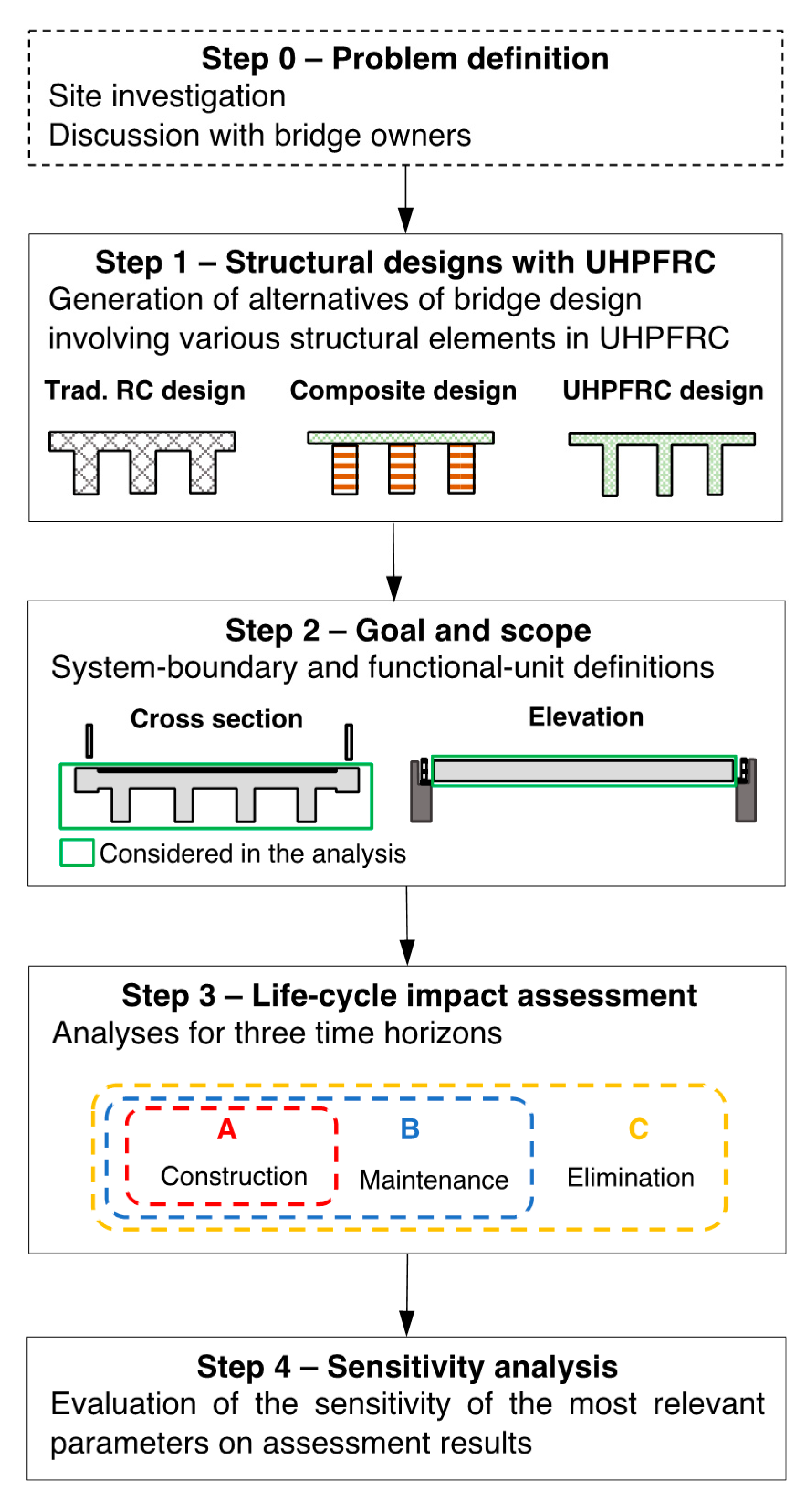
2. Materials and Methods

Bridge design can involve various structural elements made of UHPFRC, and this choice affects the design and the maintenance scheme of the structure. As this material has a significant environmental impact per unit, the total impact of the structural design is thus significantly influenced by this choice.
Comparing the environmental footprint of structural designs is challenging and requires several hypotheses to provide accurate results. The proposed methodology includes several steps (Figure 1). Once the main constraints of the problems are set, such as bridge dimensions and execution requirements, several structural designs are generated (Step 1). These designs typically involve various structural elements made with UHPFRC. For example, a full-UHPFRC bridge and designs made of a composite solution are compared with a conventional structure involving reinforced concrete without UHPFRC.
Once bridge design alternatives are generated, the system boundaries and the functional unit must be defined for the LCA (Step 2). System boundaries explicitly define processes included in the comparison, here, the cradle-to-grave comparison of bridge designs over a given service duration. Similar processes related to bridge elements involved in all design alternatives, such as bearing devices or railings, can be excluded from the system as they have a neutral effect on the bridge design comparison in terms of environmental impacts.
The functional unit quantifies the service provided by the studied system. In the case of bridge design, a typical functional unit is the use of a bridge during a defined service duration. This functional unit includes the construction of the bridge, its maintenance during the service duration, and its elimination at the end of its use.
Then, as a third step, all exchanges between the product system and the environment are quantified and listed in a life cycle impacts inventory. In Switzerland, Ecoinvent 3 is a reliable database for impact estimations on material processes, freight transportation, and waste treatments [45]. This database has been extensively used in LCA studies involving UHPFRC [37,38]. Based on this inventory, the comparative environmental impact assessment is then conducted.
The comparison can be performed using one or several metrics. For bridge-design comparison, methods include global warming potential (GWP) expressed in kg CO2 equivalent [46]; cumulative energy demand (CED) expressed in MJ [47]; global indicators such as UBP for environmental scarcity [48]; and ReCIPe for a global LCA score [49], among others. The choice of the appropriate metric(s) must be tailored for the bridge-alternative case study based on discussions with decision makers.
Then, bridge design comparisons using selected methods must be performed on three time horizons as they involve the following different levels of uncertainties:
  • Bridge construction—low uncertainties;
  • Bridge construction and maintenance—medium uncertainties;
  • Bridge construction, maintenance, and elimination—high uncertainties.
The first time-horizon assessment includes an analysis of the environmental impacts of the bridge designs until the end of construction. This phase involves the lowest level of uncertainties as the temporal proximity between the LCA and the construction phase significantly reduces the possible inaccuracies of LCA results compared to reality. The second time-horizon assessment includes the impacts of the construction plus those of the bridge maintenance over its service duration. This phase is closer to a cradle-to-grave comparison but requires additional hypotheses on future maintenance schemes. The third time-horizon assessment involves the bridge construction and maintenance as well as the elimination processes. At this stage, a comprehensive cradle-to-grave LCA is performed, but this analysis requires estimations of material disposal impacts that will occur in several decades. These estimations may be non-trivial, especially for UHPFRC, as limited experience exists for UHPFRC disposal in the literature [38].
The three-time-horizon comparison provides a comprehensive analysis of the environmental impacts of bridge designs to decision makers. Each comparison delivers complementary information on the LCA of bridge designs involving various UHPFRC elements. In order to select the alternative that minimizes the environmental impacts, the results of the three time horizons must be taken into account.
As the LCA of bridge designs inevitably requires hypotheses, the fourth step involves a sensitivity analysis on the most relevant parameters. Examples of typical sensitivity analyses in UHPFRC bridge LCAs are provided below. The environmental impact of UHPFRC highly depends on the fibre content and fibre origin [33]. Additionally, synthetic fibres could replace steel ones without significantly affecting mechanical properties [50]. The sensitivity analysis should always include a comparison between the standard and ecological mix of UHPFRC (eco-UHPFRC).
Another strong hypothesis is the service duration of the bridge. Although bridge owners typically set a minimum service duration before the construction, it is common that bridges are not replaced at the end of the theoretical use span [51]. As maintenance schemes usually involve recurring interventions, the environmental impacts of a bridge design may be significantly influenced by the bridge service duration.

3. Results

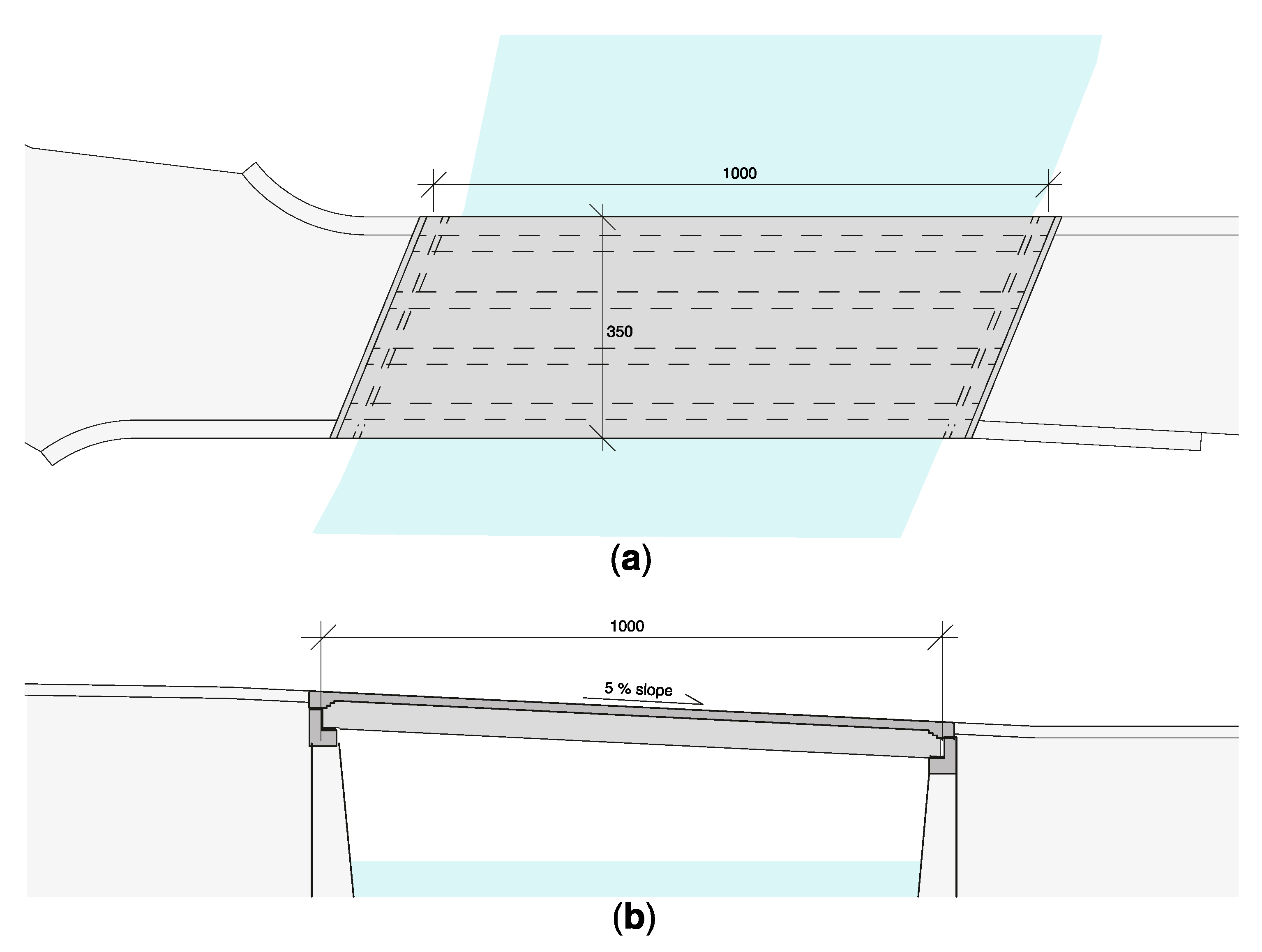
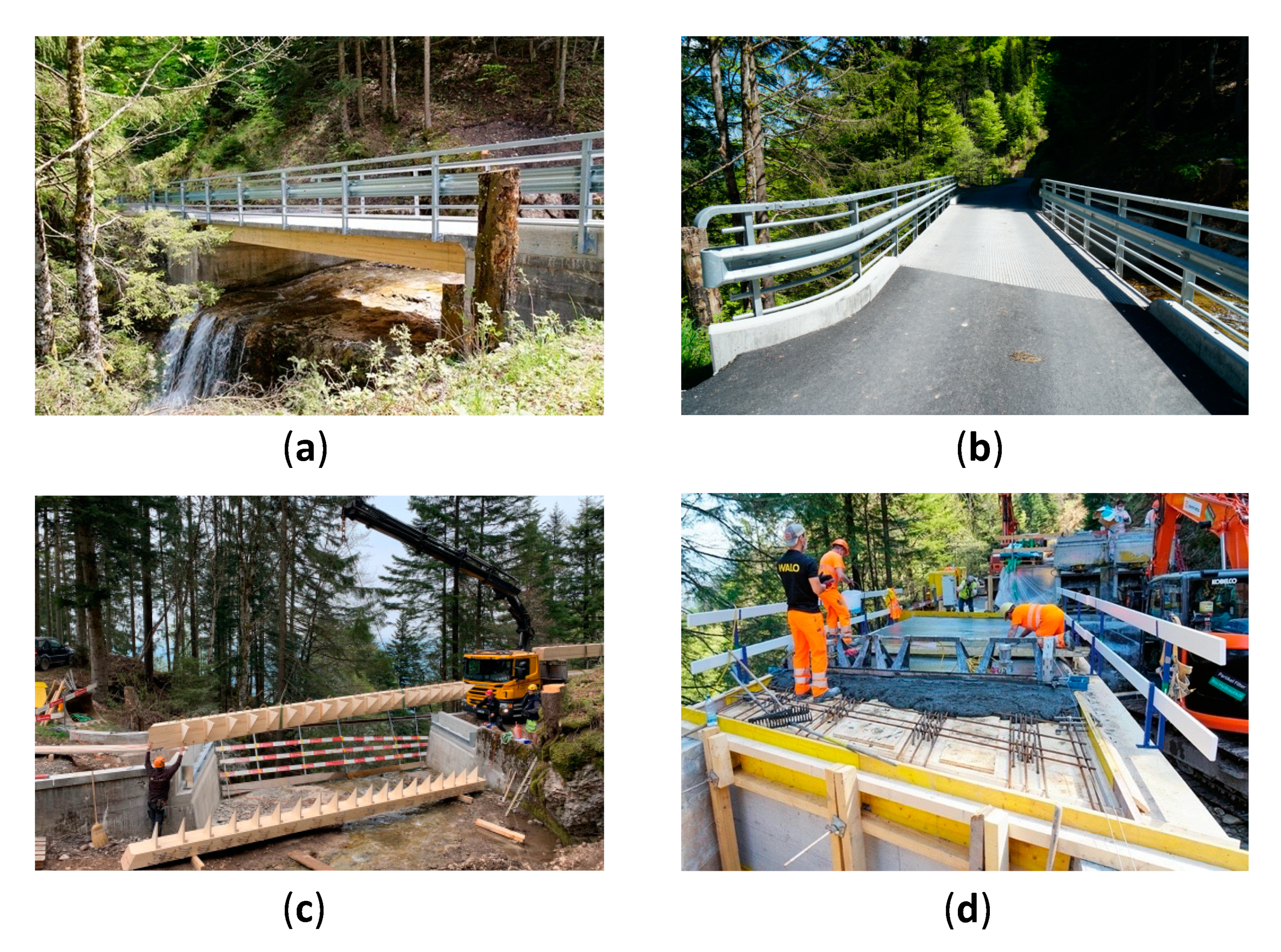
3.1. Case Study Presentation—Rigi Bridge

In this section, the main characteristics of the site are presented. The new structure connects the banks of a small river in central Switzerland. The old RC bridge was in bad condition and a repair was no longer reasonable from a technical point of view. The new structure has a single span of about 10 m for a width of 3.5 m (Figure 2).
Engineers have proposed several designs involving UHPFRC. In this study, three bridges are compared in terms of environmental impacts. The first design involves a conventional RC bridge and is called the “concrete bridge” in this study. The second alternative is a timber–UHPFRC composite structure (called the “composite bridge”), while the third structure is made entirely of UHPFRC (called the “UHPFRC bridge”). The first two bridge alternatives have been designed by engineering offices, while the third design has been designed for this study to complete the comparison. Bridge owners have chosen the composite bridge, and the structure was built in 2020.
This study presents a comparison of the three bridge-alternative environmental impacts. All structural elements that are necessary for the construction are included in the comparison. Equipment components that do not differ between alternatives, such as railings and expansion joints, are not included in this comparison.
The environmental assessments use data from the KBOB [52] and Ecoinvent 3 [45] databases for construction in Switzerland. In these databases, the current proportion of recycled material in the production of new elements is considered and material environmental impacts are calculated using a cut-off approach. In the cut-off approach, the impacts related to recycling are attributed to the product that uses recycled materials. Conversely, no impact is attributed to the product that provides the materials to be recycled. For example, in the calculation of steel production’s environmental impact, the databases sum the impacts of the recycling of its recycled share with the production of the new material, while the elimination impact is equal to zero as it is assumed that all the steel will be recycled at the time of the bridge’s disposal.
As UHPFRC is not included in these databases, UHPFRC’s environmental impact information has been collected in the literature [37,38] as these applications have been made with a similar UHPFRC mix that is considered in this study. The transportation distances have been estimated based on discussions with engineers and the literature [37,38].
Two environmental impact indicators have been selected to compare bridge designs: global warming potential (GWP), expressed in kilograms of CO2 equivalent [46], and the ecological scarcity (UBP scores) [48]. These indicators have been chosen as they provide complementary information on decisive environmental degradation factors, i.e., greenhouse gas emissions and natural resource scarcity.

3.2. Structural Designs

3.2.1. Concrete Bridge

The first bridge design is a conventional RC structure. This structure involves a cast-on-site slab (Figure 3). The required concrete volume is 25 m3, and reinforcement involves 120 kg/m3, representing 2670 kg of steel. A conventional waterproof layer (5-mm thick) and an asphalt pavement layer (80-mm thick) are included in the LCA as this pavement is required for RC structures. A conventional C30/37 is considered, and its environmental impacts are taken from the KBOB database. The mix’s design and the main characteristics of this mix are presented in Table 1.
One constraint of this alternative is that a temporary bridge must be built during the construction of the new structure. This temporary construction requires bringing and removing 300 m3 of gravel to the construction site. The environmental impacts of the temporary bridge are linked to the transportation of the gravel (distance of the closest material supplier is about 20 km) and the temporary bridge of 20 tons (distance of 50 km), as well as backfilling activities. The degradation of this temporary bridge has not been accounted for in this LCA.

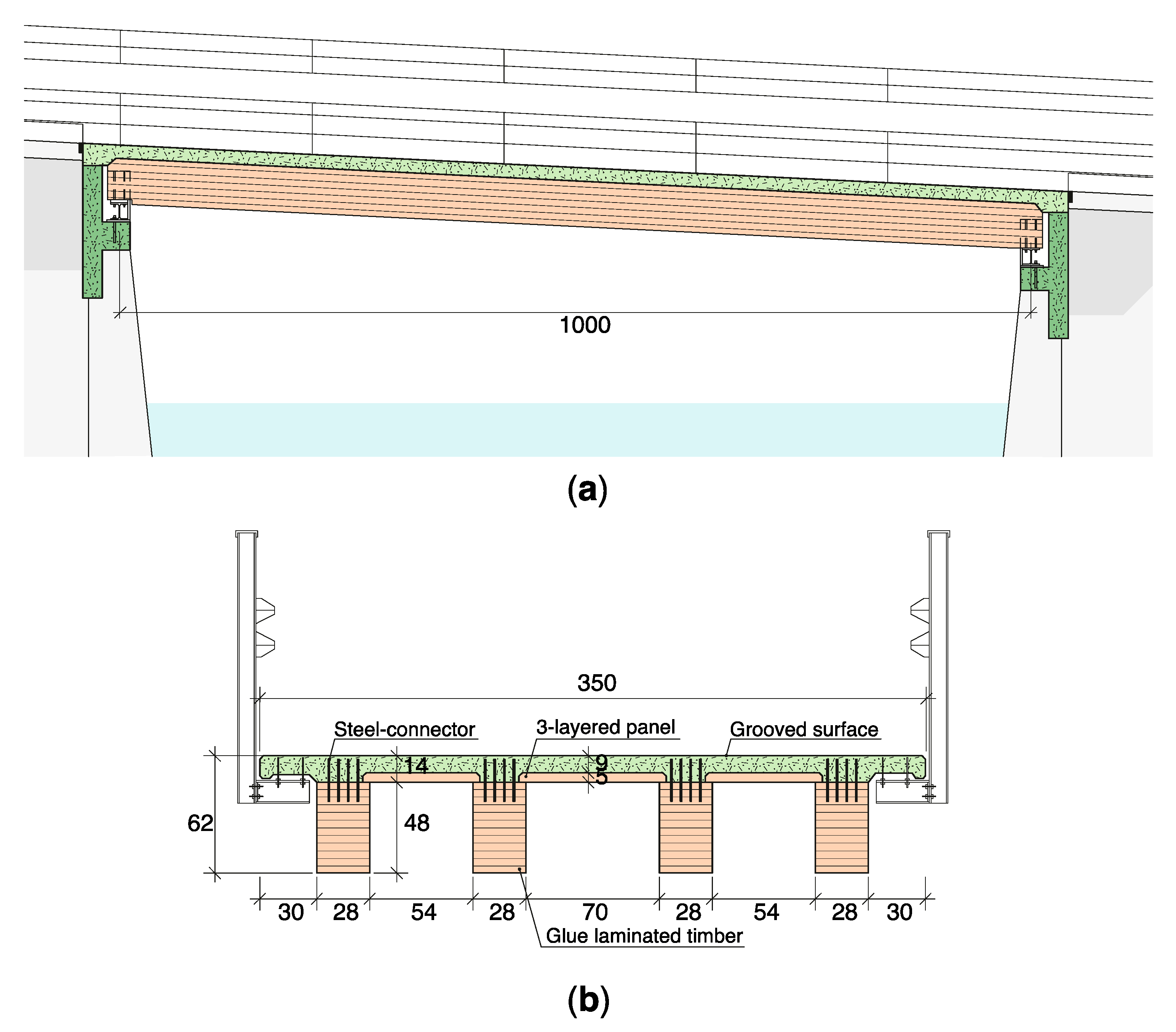
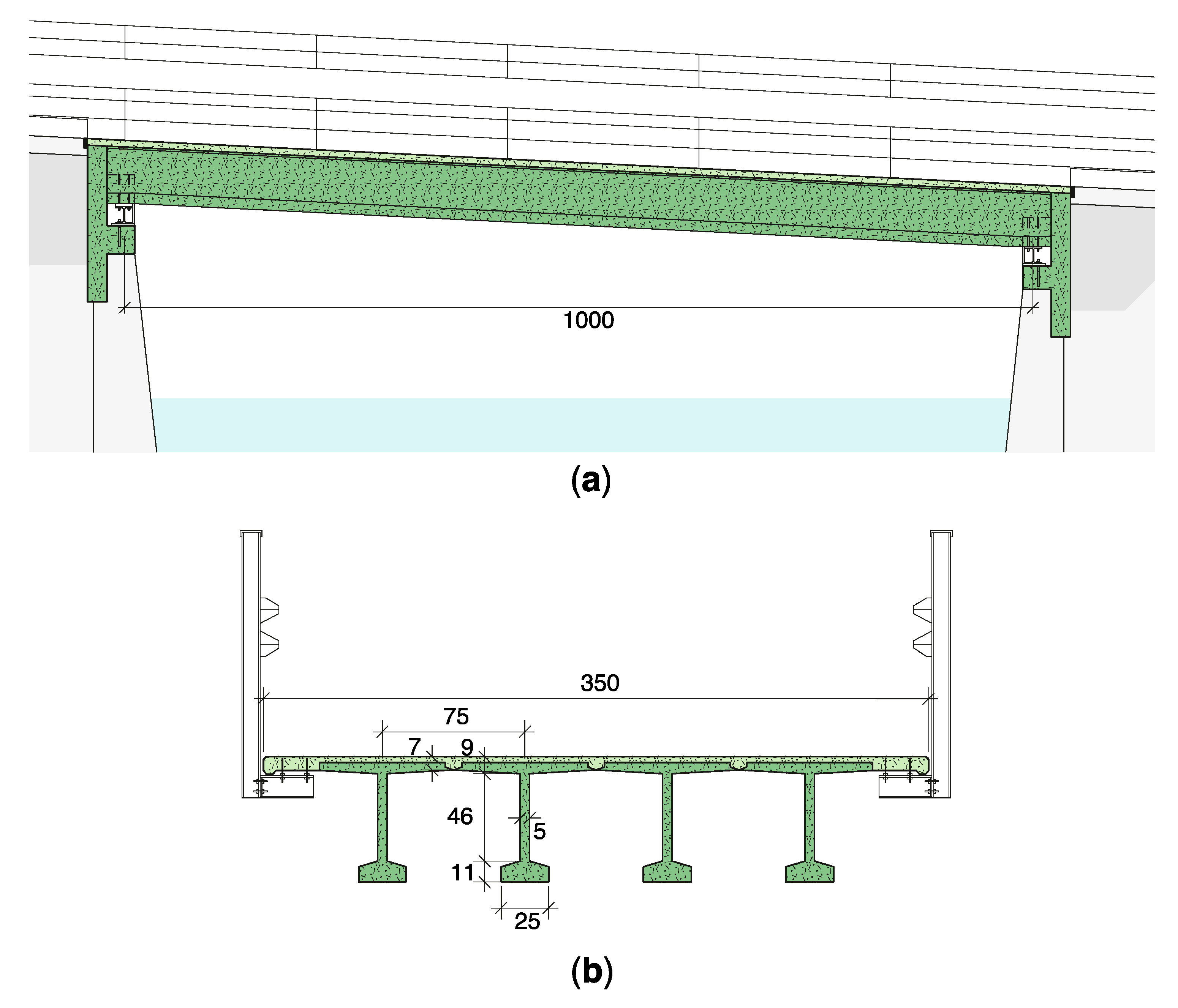
3.2.2. Composite Timber–UHPFRC Bridge

In this section, the timber–UHPFRC composite bridge is presented. In this structure, the four main girders (depth of 530 mm; width of 260 mm) are made of glued laminated timber (GL28c) from Swiss wood (Figure 4). The UHPFRC slab has a thickness between 85 and 140 mm. The shear connection between the timber and the UHPFRC is made through reinforcement bars. The UHPFRC deck is also reinforced transversally using 24 rebars with diameters of 14 mm. This deck is cast directly on wooden panels and also serves as a protective layer for the timber elements, avoiding the requirement of a waterproofing layer. No maintenance is thus expected on the timber girders over the bridge’s use span as the timber will remain dry thanks to the UHPFRC deck [44]. The UHPFRC top surface is grooved to enable vehicles to pass directly on the deck, avoiding the necessity of asphalt pavement.
The new substructure requires an abutment made of concrete (C30/37), an HEB 180 to support the timber girders, and connectors between the steel elements, concrete, and timber.
The material components required for the composite bridge are presented in Table 2. These materials include timber, steel, concrete, as well as the UHPFRC mix. The transportation distances have been estimated based on bridge-site location and discussion with involved engineers.
This design does not involve asphalt pavement as mostly industrial vehicles are expected on this case study. In most bridge cases, a small pavement may be required. In such situations, the UHPFRC deck requires only a small asphalt pavement (40-mm thick) without a waterproof membrane thanks to the UHPFRC’s properties.
This alternative is the as-built structural design (Figure 5) in order to have an LCA as representative as possible. The UHPFRC deck thickness could have been optimized between the timber girders, but this optimization has not been considered in this study.

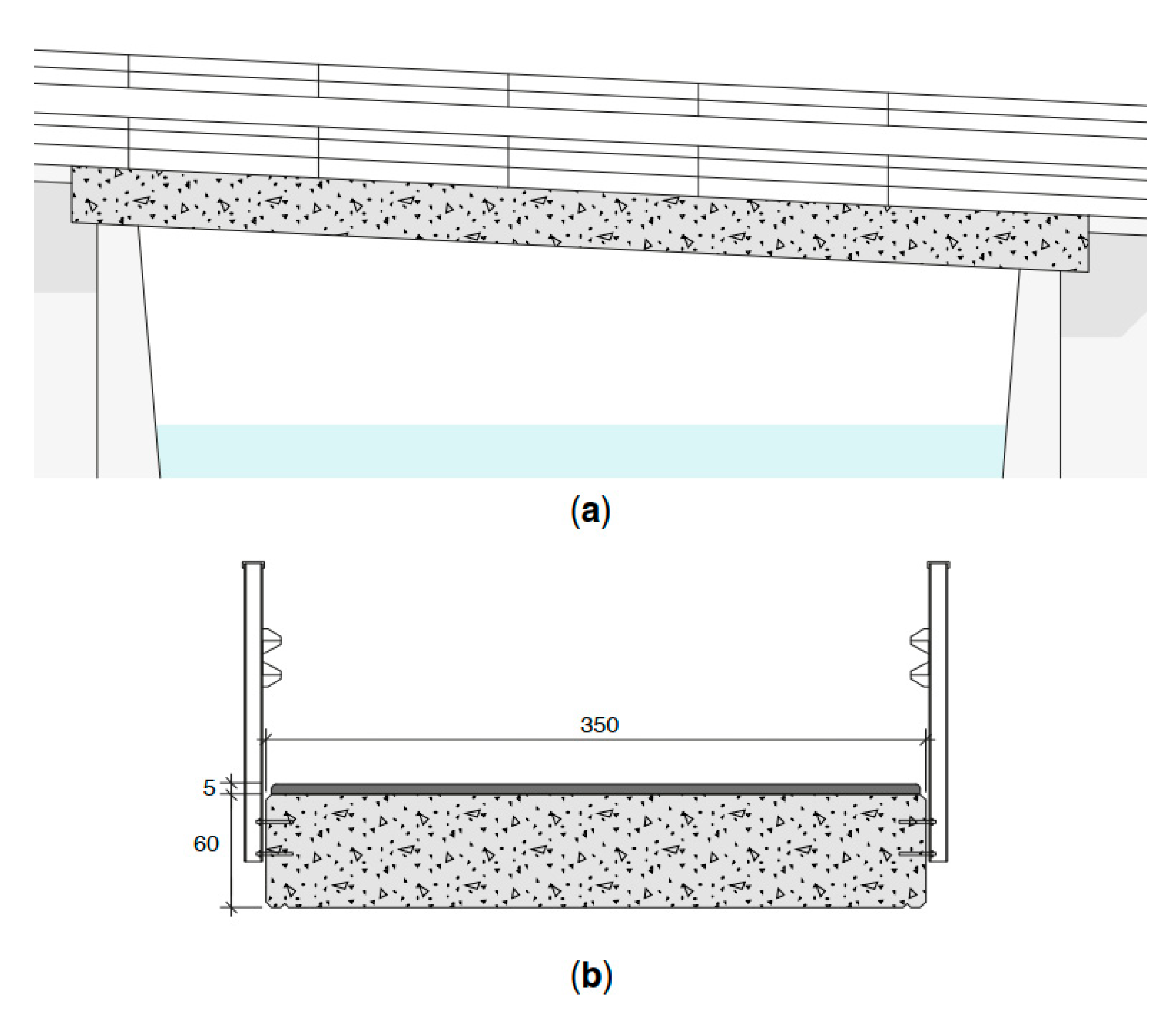
3.2.3. UHPFRC Bridge

The third bridge is made only of reinforced UHPFRC. It involves four main I-shape precast girders with a cast-on-site deck (Figure 6). The girder has a height of 660 mm (span/height ratio of 15.2). This design is strongly influenced by the first road bridge in UHPFRC in Switzerland designed by the 4th author and built in 2020 [53].
With a total substructure weight of 14 tons, this design is approximately four times lighter than the conventional RC structure (63 tons) and has a similar weight to the timber–UHPFRC solution (14.1). The required amount of UHPFRC is approximately 5 m3, only 20% higher than required by the composite structures as the deck has been optimized in this alternative. This design is thus efficient in terms of material required, taking advantage of the high performance of UHPFRC.
This superstructure design only involves two materials: UHPFRC and steel reinforcement. The same UHPFRC mix is considered as in the composite bridge (Table 2). The rebar’s impacts are taken from the KBOB database. The rebars involve 300 kg/m3, which means that 2420 kg of steel reinforcement are required. Additionally, the substructure designed for the composite bridge is also included in this alternative.

3.2.4. Design Summary

In this section, the main structural components are summarized for each structural design. The material quantities of the bridge designs, as well as the average transportation distances, are presented in Table 3. These data are the main information of bridge alternatives for performing the LCA.

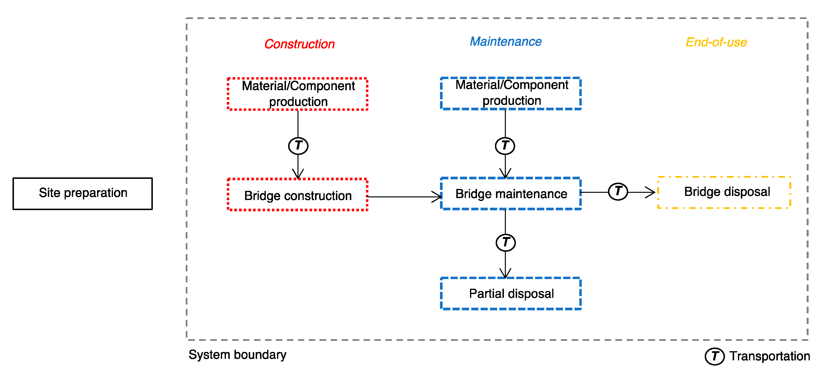
3.3. System Boundary and Functional Unit

In this section, the system boundaries and the functional unit of the LCA are presented. System boundaries explicitly define processes included in the comparison of bridge designs over a given service duration. The main differences between the three designs lie in the structural designs involving several materials, while bridge equipment components (railings, joints) are similar. The system boundaries of this LCA thus include the fabrication, maintenance, and elimination processes of the bridge’s structural elements over its service duration (Figure 7), while the equipment components (railings and joints) are not included in the environmental impact comparison.
The functional unit is the construction, the use over its service duration, and its disposal of a bridge. The LCA is performed according to this functional unit. The environmental impact evaluations follow the three time-horizon assessments (Figure 1).

3.4. Life Cycle Inventory Assessment

3.4.1. Construction Process

In this section, environmental impacts of the bridge-construction phase (first time horizon, Figure 1) are evaluated. Table 4 and Table 5 present the global warming potential (GWP) and ecological scarcity (UBP), respectively, for the construction and transport of materials for each design alternative. Most of the environmental impacts are related to the fabrication of structural elements, while GWP and UBP of transportation are relatively low due to the small distance between the construction factory of prefabricated elements and the bridge location, and light designs of composite and UHPFRC structures. The only exception is for the transport of the 300 m3 of gravel required for the temporary road during the construction of the concrete bridge. In all structures, most of the GWP is related to concrete and UHPFRC, while the UBP scores are significantly influenced by the steel reinforcements and UHPFRC. These results show that optimizing structural designs can substantially reduce the environmental footprint of construction as engineers can reduce the dimensions (thickness) of structural elements with efficient calculations.
When comparing the GWP of bridge construction (Figure 8a), the bridge designs have similar environmental impacts, between 9900 and 10,900 kg CO2eq. The full-UHPFRC solution has the largest environmental impacts, while the timber–UHPFRC composite structure has the lowest impacts. However, UBP scores (Figure 8b) show that the concrete bridge has slightly higher environmental impacts than the composite and UHPFRC alternatives. The differences between the two environmental impact metrics lie in the environmental assessment of steel (Table 4 and Table 5), as this material has much larger impacts in terms of ecological scarcity than greenhouse gas emissions.
Altogether, these metrics show that composite structures involving timber and UHPFRC can slightly lower the environmental impacts of the bridge when compared to conventional RC designs and full-UHPFRC solutions. This structure presents the benefits of timber for main girders, with a slender UHPFRC deck design.

3.4.2. Maintenance and Deconstruction

In this section, the environmental impacts of the maintenance and elimination processes are included in the LCA (second and third time horizon, Figure 1). The maintenance and elimination of elements involved in the bridge are estimated for a use span of 80 years (requirement of the bridge owners) (Table 6). Element service durations are directly linked to the structural design. For example, the timber of the composite bridge has a significant service duration as it is expected to remain dry during the service duration since the UHPFRC layer provides protection. Conversely, the concrete in the concrete bridge will be exposed to environmental ingress and is expected to deteriorate more rapidly. The maintenance of equipment components, such as joints and railings, are not included as they have a neutral effect on the LCA comparison of bridge designs.
For the concrete bridge, replacing the asphalt pavement and waterproof membrane is assumed every 20 years. Their replacement is assumed with the same materials as the ones used during the construction. A replacement of the concrete that is particularly exposed to environmental conditions is assumed after 40 years. This maintenance is estimated to correspond to 20% of concrete construction environmental impacts.
The UHPFRC and timber–UHPFRC bridge require almost no maintenance on their superstructure due to UHPFRC’s properties [18]. Additionally, dry timber does not require any significant maintenance [44]. Therefore, no significant maintenance is expected on both structures of the UHPFRC and the composite bridges.
The elimination process’s environmental impacts are taken from the KBOB database for all elements, except UHPFRC. For UHPFRC, no data exist for the elimination process’s GWP and UBP as this material has only been used recently and only a few UHPFRC structures have been disposed of. As it is a cementitious material, similar disposal solutions to the concrete are assumed. As UHPFRC has a higher compressive strength than concrete, more energy is required for disposal [38]. Following this study, it is assumed that the UHPFRC elimination’s GWP is twice as large as the concrete’s value, while the UBP scores are equivalent between UHPFRC and concrete.
Figure 9 presents the comparison of the bridge designs’ environmental impacts over the total use span (Step 3, Figure 1). When adding maintenance and elimination processes to construction, the conventional concrete structure has a larger environmental footprint than the composite and UHPFRC bridges for both the GWP and UBP metrics. For the concrete bridge, the maintenance represents approximately 30% of the total GWP and 20% of the total UBP score, while maintenance processes have no impact for both metrics on the two other bridges. This result shows that maintenance must be considered in the LCA of bridge designs as this process represents a significant part of the total environmental impacts over the bridge service duration, especially for conventional RC designs.
When the bridge deck is made of UHPFRC, the global warning potential and ecological scarcity of maintenance processes are significantly reduced as the pavement is not required and because the maintenance of the deck is avoided due to the durability properties of UHPFRC.
The composite timber–UHPFRC structure has the lowest environmental impacts in terms of the GWP. This structure reduces the global warming potential of the bridge by 34% and 6% compared to the conventional and full-UHPFRC structures, respectively.

3.5. Sensitivity Analysis

3.5.1. Bridge Service Duration

When including the maintenance scheme in the analysis, an important assumption of this LCA is the bridge service duration. Bridge owners require a minimum use span, but this limit is barely respected in practice.
The environmental impacts of bridge design are therefore assessed with respect to the service duration in Figure 10, as maintenance is typically performed regularly. For the concrete bridge, it is assumed that the asphalt pavement and waterproof layer are replaced every 20 years, and significant maintenance on the concrete structure is performed every 40 years. No maintenance is expected on the structures of the UHPFRC and composite bridges.
Since the first maintenance, the environmental impact of the concrete bridge is more significant than the UHPFRC solution. The conventional bridge design thus has a larger environmental impact than the solutions involving UHPFRC and is not recommended. If at least one maintenance was expected on the concrete bridge, the environmental impact of this alternative would be the largest. These results confirm that the composite bridge has smaller environmental impacts even if the service duration of the structure is small or the maintenance on the other alternatives is reduced.

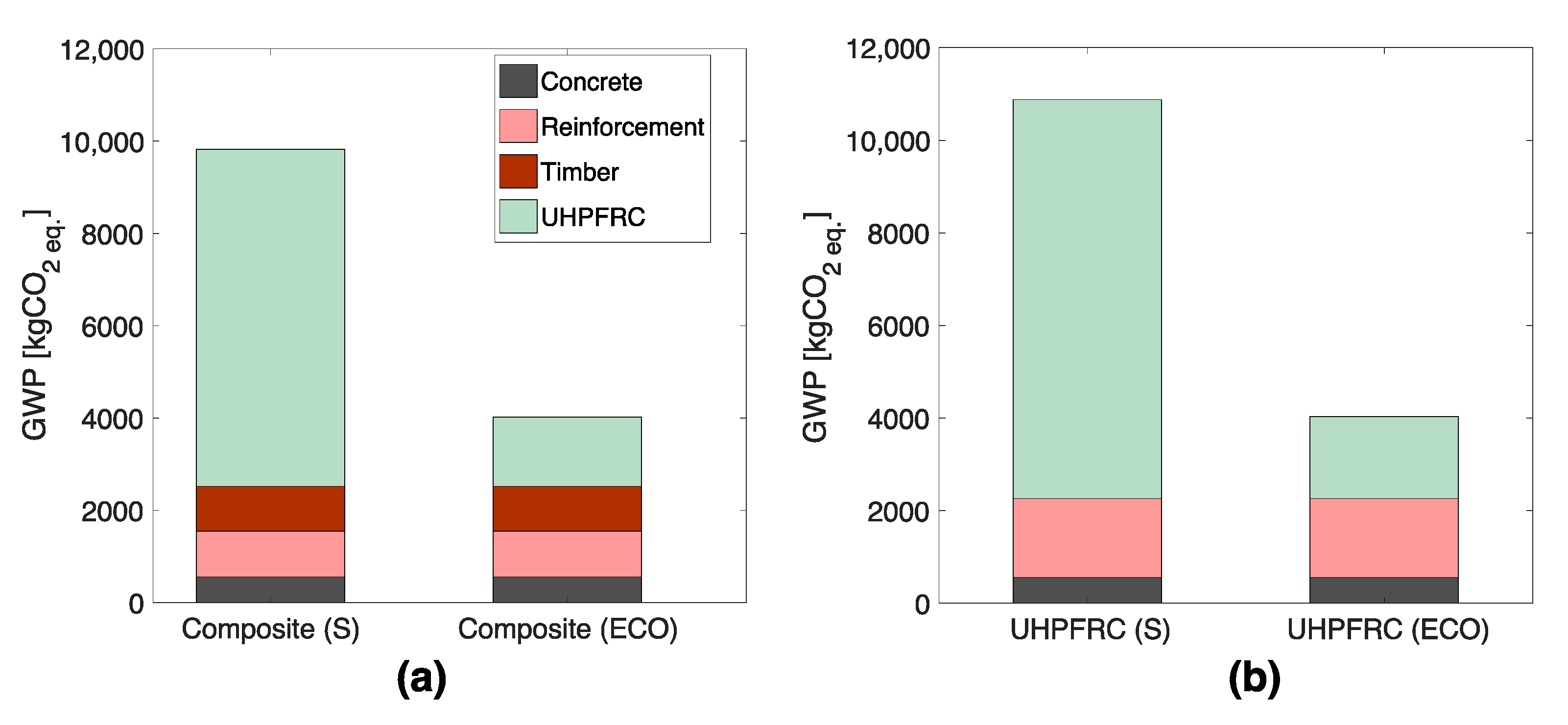
3.5.2. Environmentally Friendly UHPFRC Mix

An environmentally friendly mix of UHPFRC has been recently developed where two improvements are made to the standard mix [50]. First, steel fibres are replaced by ultra-high molecular weight polyethylene (UHMW-PE) fibres. Second, 50% of clinker is replaced with limestone fillers.
As this ECO-UHPFRC provides similar mechanical properties to the standard mix, similar bridge designs are obtained. Additionally, the maintenance and elimination processes of UHPFRC are not affected as the durability properties of ECO-UHPFRC are equivalent to the conventional mix.
The influence of ECO-UHPFRC in terms of global warming potential is presented in Figure 11. Environmental impacts of the construction of the composite timber–UHPFRC and full-UHPFRC structures are compared using standard (S) and ECO-UHPFRC (ECO) mixes.
Figure 11 shows that the selected UHPFRC mix has a significant influence on the environmental impacts of the construction. Since UHMW-PE fibres have smaller environmental impacts and less cement is involved in their mix, the use of ECO-UHPFRC significantly reduces (up to 63%) the global warming potential of bridges involving UHPFRC elements without requiring important adaptation of structural designs. These results agree with the previous study of [37], where ECO-UHPFRC is compared to the conventional mix for existing bridge rehabilitation.
As the selected UHPFRC mix has a small impact on structural-design dimensions [50], this material choice should thus be discussed with decision-makers to reduce the environmental footprint of new infrastructure.

3.5.3. CO2 Stored in the Timber

In the KBOB database [52], the timber is assumed to come from a sustainable harvest where the carbon pool is kept constant. Additionally, it is assumed that the timber is half recycled and half disposed of. Consequently, an assumption is made in this data that half of the timber has a neutral CO2 emission, and for this half, the construction GWP is only linked to the girder fabrication activities such as the glued-lamination process. For this reason, CLT timber has much higher environmental impacts than mass timber both in terms of global warming potential and ecological scarcity [52].
As this database has been built for construction in Switzerland, this assumption is made mostly for buildings. However, covered timber bridges have shown very long durability properties [44]. For the composite structure, the timber is effectively protected by the UHPFRC deck and will likely remain dry. At the end of the service duration of the bridge, it is possible that the timber girders will be in good condition and will not be disposed of but instead reused in another structure, even if this hypothesis has not been considered in the results of this study. This practice has been documented for the covered timber bridge of Eglisau [54].
In the timber–UHPFRC composite bridge, the assumption to include the CO2 stored in the timber in the LCA could be justified if it is expected that timber girders will be reused. In such cases, the positive environmental impacts of timber could be considered in the LCA either partially or completely.
The amount of CO2 stored in wood depends on several factors, such as the tree type and its age. In this study, a rough estimation is that an equivalent of 1 ton of CO2 is stored in 1 ton of timber in Swiss construction [55,56].
When including the positive environmental impacts of lumber in the LCA of the timber–UHPFRC bridge, 63% of CO2eq emissions of the composite bridge construction are compensated if the ECO-UHPFRC is used. As it is the only bridge alternative involving timber in this study, this sensitivity analysis provides another argument to recommend this bridge design based on the LCA.

4. Discussion

This study provides a life cycle analysis of several bridge designs. Three design alternatives that involve conventional and UHPFRC designs are compared. Over the entire service duration of the bridge, the composite timber–UHPFRC structure has the lowest environmental impacts in terms of global warming potential and ecological scarcity.
This study shows that significant differences are obtained between bridge designs in terms of environmental impacts. This criterion should be considered in the selection of appropriate bridge designs in addition to traditional design criteria such as construction costs, structural efficiency, and duration of the construction work.
The environmental impacts of additional kilometres of users due to traffic deviation of bridge construction have not been taken into account in this study for the following reasons. The bridge used for the case study is located on a secondary road with little traffic. The second and third alternatives involve mostly prefabricated elements, while a temporary road is included in the environmental impacts of the first bridge. These specificities are expected to lead to a small environmental footprint of the traffic deviation compared to construction impacts.
In this study, three bridge designs have been considered. In practice, the composite timber–UHPFRC structure is the design that has been chosen by engineers and bridge owners, also because the construction cost was lowest, while the concrete structure was the only other proposed alternative. Other bridge designs, such as steel–concrete and timber–concrete composites, have not been included in this study. These alternatives were discarded by bridge owners at an early stage, mainly due to their construction time. A full-timber structure would not be possible for the required bridge service duration of 80 years due to the durability issues of exposed wood. The third bridge design (full-UHPFRC structure) has been designed for this study and was not considered by engineers before construction, as this type of structure has only been built once in Switzerland.
Several parameters of the designs have been made based on engineering judgment. Since these decisions influence the required quantities of materials, environmental impacts could differ. For instance, glue-laminated timber has been selected over solid timber for static reasons in the composite bridge. As solid timber has smaller environmental impacts [52], choosing this type of timber would have slightly reduced the total environmental impacts of this alternative (Figure 8).
Future work consists of the optimization of the UHPFRC bridge design based on environmental impacts. This optimization algorithm will thus be able to provide an optimal UHPFRC bridge design given structural, design, and code constraints.

5. Conclusions

This paper presents an environmental impact comparison of bridge designs involving UHPFRC over three time horizons. The life cycle analysis is performed using two metrics: the potential global warming and ecological scarcity. Three bridge designs involving a conventional reinforced concrete, a composite timber–UHPFRC, and a full-UHPFRC bridge structure are compared. The following conclusions are made:
  • Environmental impacts of bridges should include three time horizon assessments: first considering only the construction phase, then including the scheduled maintenance, and finally adding the elimination.
  • Maintenance represents a large part of the impacts of conventional structures. The use of UHPFRC for bridge decks significantly reduces the impacts of maintenance.
  • The composite timber–UHPFRC bridge has slightly lower impacts than the full-UHPFRC bridge. Both appreciably reduce environmental impacts when compared to conventional reinforced concrete structures, showing that using UHPFRC in road-bridge design can lead to less environmentally detrimental bridge construction.

Author Contributions

Conceptualization, N.B. and E.B.; methodology, N.B. and C.K.; formal analysis, N.B. and C.K.; resources, E.K.; writing—original draft preparation, N.B.; writing—review and editing, N.B., C.K., E.K. and E.B.; supervision, E.B. All authors have read and agreed to the published version of the manuscript.

Funding

The research received no external funding.

Institutional Review Board Statement

Not applicable.

Informed Consent Statement

Not applicable.

Data Availability Statement

Not applicable.

Conflicts of Interest

The authors declare no conflict of interest.

References

  1. Bajželj, B.; Allwood, J.M.; Cullen, J.M. Designing Climate Change Mitigation Plans That Add Up. Environ. Sci. Technol. 2013, 47, 8062–8069. [Google Scholar] [CrossRef] [PubMed]
  2. Favier, A.; Scrivener, K.; Habert, G. Decarbonizing the Cement and Concrete Sector: Integration of the Full Value Chain to Reach Net Zero Emissions in Europe. IOP Conf. Ser. Earth Environ. Sci. 2019, 225, 012009. [Google Scholar] [CrossRef]
  3. Habert, G.; Miller, S.A.; John, V.M.; Provis, J.L.; Favier, A.; Horvath, A.; Scrivener, K.L. Environmental Impacts and Decarbonization Strategies in the Cement and Concrete Industries. Nat. Rev. Earth Environ. 2020, 1, 559–573. [Google Scholar] [CrossRef]
  4. Damineli, B.L.; Kemeid, F.M.; Aguiar, P.S.; John, V.M. Measuring the Eco-Efficiency of Cement Use. Cem. Concr. Compos. 2010, 32, 555–562. [Google Scholar] [CrossRef]
  5. Proske, T.; Hainer, S.; Rezvani, M.; Graubner, C.-A. Eco-Friendly Concretes with Reduced Water and Cement Contents—Mix Design Principles and Laboratory Tests. Cem. Concr. Res. 2013, 51, 38–46. [Google Scholar] [CrossRef]
  6. Teh, S.H.; Wiedmann, T.; Castel, A.; de Burgh, J. Hybrid Life Cycle Assessment of Greenhouse Gas Emissions from Cement, Concrete and Geopolymer Concrete in Australia. J. Clean. Prod. 2017, 152, 312–320. [Google Scholar] [CrossRef] [Green Version]
  7. Scrivener, K.; Martirena, F.; Bishnoi, S.; Maity, S. Calcined Clay Limestone Cements (LC3). Cem. Concr. Res. 2018, 114, 49–56. [Google Scholar] [CrossRef]
  8. Ghyoot, M.; Devlieger, L.; Billiet, L.; Warnier, A. Rotor Déconstruction et réemploi: Comment faire circuler les éléments de construction; Presses Polytechniques et Universitaires Romandes: Lausanne, Switzerland, 2018; ISBN 978-2-88915-239-1. [Google Scholar]
  9. Huuhka, S.; Kaasalainen, T.; Hakanen, J.H.; Lahdensivu, J. Reusing Concrete Panels from Buildings for Building: Potential in Finnish 1970s Mass Housing. Resour. Conserv. Recycl. 2015, 101, 105–121. [Google Scholar] [CrossRef]
  10. Addis, B. Building with Reclaimed Components and Materials: A Design Handbook for Reuse and Recycling; Earthscan: London, UK, 2006; ISBN 978-1-84407-274-3. [Google Scholar]
  11. Barriers for Deconstruction and Reuse/Recycling of Construction Materials. Rapport CIB 397; Nakajima, S., Russell, M., Eds.; CIB: Rotterdam, The Netherlands, 2014. [Google Scholar]
  12. Pamenter, S.; Myers, R.J. Decarbonizing the Cementitious Materials Cycle: A Whole-Systems Review of Measures to Decarbonize the Cement Supply Chain in the UK and European Contexts. J. Ind. Ecol. 2021, 25, 359–376. [Google Scholar] [CrossRef]
  13. Graybeal, B.; Brühwiler, E.; Kim, B.-S.; Toutlemonde, F.; Voo, Y.L.; Zaghi, A. International Perspective on UHPC in Bridge Engineering. J. Bridge Eng. 2020, 25, 04020094. [Google Scholar] [CrossRef]
  14. Brühwiler, E.; Denarié, E. Rehabilitation and Strengthening of Concrete Structures Using Ultra-High Performance Fibre Reinforced Concrete. Struct. Eng. Int. 2013, 23, 450–457. [Google Scholar] [CrossRef]
  15. Brühwiler, E. UHPFRC Technology to Enhance the Performance of Existing Concrete Bridges. Struct. Infrastruct. Eng. 2020, 16, 94–105. [Google Scholar] [CrossRef]
  16. Oesterlee, C. Structural Response of Reinforced UHPFRC and RC Composite Members. Ph.D. Thesis, EPFL, Lausanne, Switzerland, 2010. [Google Scholar]
  17. Brühwiler, E. Structural UHPFRC to Enhance Bridges. In Proceedings of the 2nd International Conference on UHPC Materials and Structures UHPC 2018, Fuzhou, China, 7–10 November 2018; Volume 129, pp. 140–158. [Google Scholar]
  18. Paul, S.C.; van Zijl, G.P.; Šavija, B. Effect of Fibers on Durability of Concrete: A Practical Review. Materials 2020, 13, 4562. [Google Scholar] [CrossRef] [PubMed]
  19. Denarié, E.; Brühwiler, E. Cast-on Site UHPFRC for Improvement of Existing Structures—Achievements over the Last 10 Years in Practice and Research. In Proceedings of the HPFRCC7: 7th workshop on High Performance Fiber Reinforced Cement Composites, Stuttgart, Germany, 1–3 June 2015. [Google Scholar]
  20. Toutlemonde, F.; Roenelle, P.; Hajar, Z.; Simon, A.; Lapeyrere, R.; Martin, R.; Ramanich, S.; BARON, L. Long-Term Material Performance Checked on World’s Oldest UHPFRC Road Bridges at Bourg-Lès-Valence. In Proceedings of the RILEM-fib-AFGC Int. Symposium on Ultra-High Performance Fibre-Reinforced Concrete, UHPFRC 2013, Marseille, France, 1–3 October 2013. [Google Scholar]
  21. Coenen, T.B.; Santos, J.; Fennis, S.A.; Halman, J.I. Development of a Bridge Circularity Assessment Framework to Promote Resource Efficiency in Infrastructure Projects. J. Ind. Ecol. 2021, 25, 288–304. [Google Scholar] [CrossRef]
  22. CEN EN 15978: 2011 Sustainability of Construction Works. Assessment of Environmental Performance of Buildings. Calculation Method. 2011. Available online: https://www.en-standard.eu/bs-en-15978-2011-sustainability-of-construction-works-assessment-of-environmental-performance-of-buildings-calculation-method/ (accessed on 29 October 2021).
  23. International Organisation for Standardisation ISO 14040 Environmental Management—Life Cycle Assessment—Principles and Framework. Available online: https://www.iso.org/cms/render/live/en/sites/isoorg/contents/data/standard/03/74/37456.html (accessed on 7 May 2021).
  24. Du, G.; Safi, M.; Pettersson, L.; Karoumi, R. Life Cycle Assessment as a Decision Support Tool for Bridge Procurement: Environmental Impact Comparison among Five Bridge Designs. Int. J. Life Cycle Assess. 2014, 19, 1948–1964. [Google Scholar] [CrossRef]
  25. Du, G.; Karoumi, R. Environmental Life Cycle Assessment Comparison between Two Bridge Types: Reinforced Concrete Bridge and Steel Composite Bridge. In Proceedings of the International Conference on Sustainable Construction Materials & Technologies, Kyoto, Japan, 18–21 August 2013. [Google Scholar]
  26. Du, G.; Karoumi, R. Life Cycle Assessment Framework for Railway Bridges: Literature Survey and Critical Issues. Struct. Infrastruct. Eng. 2014, 10, 277–294. [Google Scholar] [CrossRef]
  27. Hettinger, A.; Birat, J.; Hechler, O.; Braun, M. Sustainable bridges–LCA for a composite and a concrete bridge. In Economical Bridge Solutions Based on Innovative Composite Dowels and Integrated Abutments; Springer: Berlin/Heidelberg, Germany, 2015; pp. 45–56. [Google Scholar]
  28. Kendall, A.; Keoleian, G.A.; Helfand, G.E. Integrated Life-Cycle Assessment and Life-Cycle Cost Analysis Model for Concrete Bridge Deck Applications. J. Infrastruct. Syst. 2008, 14, 214–222. [Google Scholar] [CrossRef]
  29. Pang, B.; Yang, P.; Wang, Y.; Kendall, A.; Xie, H.; Zhang, Y. Life Cycle Environmental Impact Assessment of a Bridge with Different Strengthening Schemes. Int. J. Life Cycle Assess. 2015, 20, 1300–1311. [Google Scholar] [CrossRef]
  30. Penadés-Plà, V.; García-Segura, T.; Martí, J.V.; Yepes, V. An Optimization-LCA of a Prestressed Concrete Precast Bridge. Sustainability 2018, 10, 685. [Google Scholar] [CrossRef] [Green Version]
  31. Zhang, Y.-R.; Wu, W.-J.; Wang, Y.-F. Bridge Life Cycle Assessment with Data Uncertainty. Int. J. Life Cycle Assess. 2016, 21, 569–576. [Google Scholar] [CrossRef]
  32. Randl, N.; Steiner, T.; Ofner, S.; Baumgartner, E.; Mészöly, T. Development of UHPC Mixtures from an Ecological Point of View. Constr. Build. Mater. 2014, 67, 373–378. [Google Scholar] [CrossRef] [Green Version]
  33. Stengel, T.; Schießl, P. 22—Life cycle assessment (LCA) of ultra high performance concrete (UHPC) structures. In Eco-Efficient Construction and Building Materials; Pacheco-Torgal, F., Cabeza, L.F., Labrincha, J., de Magalhães, A., Eds.; Woodhead Publishing: Sawston, UK, 2014; pp. 528–564. ISBN 978-0-85709-767-5. [Google Scholar]
  34. Pushkar, S.; Ribakov, Y. Life-Cycle Assessment of Strengthening Pre-Stressed Normal-Strength Concrete Beams with Different Steel-Fibered Concrete Layers. Sustainability 2020, 12, 7958. [Google Scholar] [CrossRef]
  35. Keoleian, G.A.; Kendall, A.; Dettling, J.E.; Smith, V.M.; Chandler, R.F.; Lepech, M.D.; Li, V.C. Life Cycle Modeling of Concrete Bridge Design: Comparison of Engineered Cementitious Composite Link Slabs and Conventional Steel Expansion Joints. J. Infrastruct. Syst. 2005, 11, 51–60. [Google Scholar] [CrossRef]
  36. Habert, G.; Denarié, E.; Šajna, A.; Rossi, P. Lowering the Global Warming Impact of Bridge Rehabilitations by Using Ultra High Performance Fibre Reinforced Concretes. Cem. Concr. Compos. 2013, 38, 1–11. [Google Scholar] [CrossRef] [Green Version]
  37. Hajiesmaeili, A.; Pittau, F.; Denarié, E.; Habert, G. Life Cycle Analysis of Strengthening Existing RC Structures with R-PE-UHPFRC. Sustainability 2019, 11, 6923. [Google Scholar] [CrossRef] [Green Version]
  38. Sameer, H.; Weber, V.; Mostert, C.; Bringezu, S.; Fehling, E.; Wetzel, A. Environmental Assessment of Ultra-High-Performance Concrete Using Carbon, Material, and Water Footprint. Materials 2019, 12, 851. [Google Scholar] [CrossRef] [Green Version]
  39. O’Born, R. Life Cycle Assessment of Large Scale Timber Bridges: A Case Study from the World’s Longest Timber Bridge Design in Norway. Transp. Res. Part D Transp. Environ. 2018, 59, 301–312. [Google Scholar] [CrossRef]
  40. Rodrigues, J.N.; Providência, P.; Dias, A.M.P.G. Sustainability and Lifecycle Assessment of Timber-Concrete Composite Bridges. J. Infrastruct. Syst. 2017, 23, 04016025. [Google Scholar] [CrossRef]
  41. Fragiacomo, M.; Gregori, A.; Xue, J.; Demartino, C.; Toso, M. Timber-Concrete Composite Bridges: Three Case Studies. J. Traffic Transp. Eng. Engl. Ed. 2018, 5, 429–438. [Google Scholar] [CrossRef]
  42. Pousette, A.; Malo, K.A.; Thelandersson, S.; Fortino, S.; Salokangas, L.; Wacker, J. Durable Timber Bridges—Final Report and Guidelines; SP Rapport; RISE Research Institutes of Sweden: Skellefteå, Sweden, 2017; p. 177. [Google Scholar]
  43. Meyer-Veltrup, L.; Brischke, C.; Niklewski, J.; Frühwald Hansson, E. Design and Performance Prediction of Timber Bridges Based on a Factorization Approach. Wood Mater. Sci. Eng. 2018, 13, 167–173. [Google Scholar] [CrossRef]
  44. Mahnert, K.-C.; Hundhausen, U. A Review on the Protection of Timber Bridges. Wood Mater. Sci. Eng. 2018, 13, 152–158. [Google Scholar] [CrossRef]
  45. Wernet, G.; Bauer, C.; Steubing, B.; Reinhard, J.; Moreno-Ruiz, E.; Weidema, B. The Ecoinvent Database Version 3 (Part I): Overview and Methodology. Int. J. Life Cycle Assess. 2016, 21, 1218–1230. [Google Scholar] [CrossRef]
  46. Krey, V.; Masera, O.; Blanford, G.; Bruckner, T.; Cooke, R.; Fisher-Vanden, K.; Haberl, H.; Hertwich, E.; Kriegler, E.; Mueller, D. Annex 2-Metrics and Methodology. In Climate Change 2014: Mitigation of Climate Change. IPCC Working Group III Contribution to AR5; Cambridge University Press: Cambridge, UK, 2014. [Google Scholar]
  47. Hischier, R.; Weidema, B.; Althaus, H.-J.; Bauer, C.; Doka, G.; Dones, R.; Frischknecht, R.; Hellweg, S.; Humbert, S.; Jungbluth, N. Implementation of Life Cycle Impact Assessment Methods; Ecoinvent Report. 2010. Available online: https://ecoinvent.org/wp-content/uploads/2020/08/201007_hischier_weidema_implementation_of_lcia_methods.pdf (accessed on 29 October 2021).
  48. Frischknecht, R.; Knöpfel, S.B. Ecological Scarcity 2013—New Features and Its Application in Industry and Administration—54th LCA Forum, Ittigen/Berne, Switzerland, December 5, 2013. Int. J. Life Cycle Assess. 2014, 19, 1361–1366. [Google Scholar] [CrossRef]
  49. Goedkoop, M.; Heijungs, R.; Huijbregts, M.; De Schryver, A.; Struijs, J.; Van Zelm, R. ReCiPe 2008: A life cycle impact assessment method which comprises harmonised category indicators at the midpoint and the endpoint level. Impact Assess. 2009, 1, 1–126. [Google Scholar]
  50. Hajiesmaeili, A.; Denarié, E. Next Generation UHPFRC for Sustainable Structural Applications. In Proceedings of the DSCS 2018: 2nd International Workshop on Durability and Sustainability of Concrete Structures, Moscow, Russia, 6–7 June 2018. [Google Scholar]
  51. Brühwiler, E.; Vogel, T.; Lang, T.; Lüchinger, P. Swiss Standards for Existing Structures. Struct. Eng. Int. 2012, 22, 275–280. [Google Scholar] [CrossRef]
  52. Koordinationskonferenz der Bau- und Liegenschaftsorgane der öffentlichen Bauherren KBOB. Ökobilanzdaten im Baubereich 2009/1:2016. Available online: https://www.kbob.admin.ch/kbob/de/home/themen-leistungen/nachhaltiges-bauen/oekobilanzdaten_baubereich.html (accessed on 3 June 2021).
  53. Walo UHFB Bridge in Tavern. Available online: https://walo.ch/projekte/uhfb-bruecke-in-taverne/ (accessed on 9 March 2021).
  54. Fivet, C.; Brütting, J. Nothing Is Lost, Nothing Is Created, Everything Is Reused: Structural Design for a Circular Economy. Struct. Eng. 2020, 98, 74–81. [Google Scholar]
  55. Profft, I.; Mund, M.; Weber, G.-E.; Weller, E.; Schulze, E.-D. Forest Management and Carbon Sequestration in Wood Products. Eur. J. For. Res. 2009, 128, 399–413. [Google Scholar] [CrossRef] [Green Version]
  56. Werner, F.; Taverna, R.; Hofer, P.; Richter, K. Carbon Pool and Substitution Effects of an Increased Use of Wood in Buildings in Switzerland: First Estimates. Ann. For. Sci. 2005, 62, 889–902. [Google Scholar] [CrossRef] [Green Version]
Figure 1. Flowchart of the methodology to evaluate the environmental impacts of structural designs involving UHPFRC elements.
Sustainability 13 12399 g001
Figure 2. Bridge situation and main dimensions: (a) plan view; (b) elevation.
Sustainability 13 12399 g002
Figure 3. Design of the concrete bridge: (a) elevation, (b) cross-section.
Sustainability 13 12399 g003
Figure 4. Design of the composite UHPFRC-timber bridge: (a) elevation; (b) cross-section.
Sustainability 13 12399 g004
Figure 5. Rigi Bridge and its construction: (a,b) bridge photographs; (c) installation of timber girders; (d) Casting of UHPFRC.
Sustainability 13 12399 g005
Figure 6. Design of the UHPFRC bridge: (a) elevation; (b) cross-section.
Sustainability 13 12399 g006
Figure 7. System boundary for the life-cycle assessment of bridge design.
Sustainability 13 12399 g007
Figure 8. Environmental impacts of bridge-design construction: (a) Global warming potential; (b) Ecological scarcity (UBP points).
Sustainability 13 12399 g008
Figure 9. Environmental impacts of bridge designs over the use span, including construction, maintenance, and elimination processes: (a) Global warming potential; (b) Ecological scarcity (UBP points).
Sustainability 13 12399 g009
Figure 10. Influence of the service duration on the environmental impacts of bridge designs.
Sustainability 13 12399 g010
Figure 11. Influence of using an environmentally friendly UHPFRC on the bridge’s ecological footprint in terms of global warming potential: (a) Timber–UHPFRC composite bridge; (b) UHPFRC bridge.
Sustainability 13 12399 g011
Table 1. Material mix for the concrete bridge—concrete C30/37.
Material ComponentsDistance [km]Mix Design [kg/m3]Total [kg]
CEM I 42.5 R503507791
Water-18014,469
Sand206504007
Gravel20120026,712
Superplasticizer305111
Table 2. Material mix for the UHPFRC—UHPFRC-timber bridge.
Material ComponentsDistance [km]Mix Design [kg/m3]Total [kg]
Timber75-3000
Rebars and connectors100-1410
Concrete50 6000
UHPFRC
CEM III/N 32.5 N5012775195
Silica fume (I)-96391
Fine quartz sand (I)206432616
Water 173704
Superplasticizer5042171
Steel fibres21,0002981212
Table 3. Material quantity required in bridge designs.
MaterialQuantity [kg]Average Distance [km]
Concrete bridge
Concrete53,42450
Steel2612100
Asphalt Pavement712350
Waterproofing membrane204100
Gravel (temporary bridge)450020
Total63,422
UHPFRC bridge
UHPFRC beam12,471100
Steel2419100
Concrete600050
Total20,987
Composite bridge
UHPFRC10,57750
Steel1410100
Timber300075
Concrete600050
Total20,890
Table 4. Environmental impacts of bridge construction—Global warming potential.
MaterialFabrication
GWP [kg CO2eq]
Transport
GWP [kg CO2eq]
Total Construction
GWP [kg CO2eq]
Concrete bridge
Concrete47555825337
Rebars1822581880
Temporary bridge24722002447
Asphalt47978556
Waterproofing membrane1804184
Total7235317010,404
UHPFRC bridge
UHPFRC83402728612
Steel1650531703
Concrete53465599
Total10,52439010,914
Composite bridge
UHPFRC70732317304
Steel96031992
Timber94525970
Concrete53465599
Total95143529866
Table 5. Environmental impacts of bridge construction—environmental scarcity (UBP score).
MaterialFabrication
UBP × 106 [-]
Transport
UBP × 106 [-]
Total Construction
UBP × 106 [-]
Concrete bridge
Concrete3.600.824.41
Rebars7.160.087.24
Temporary bridge0.293.063.35
Asphalt0.620.110.73
Waterproofing membrane0.290.060.30
Total11.74.3616.0
UHPFRC bridge
UHPFRC7.960.388.34
Rebars6.480.076.56
Concrete0.400.090.49
Total14.90.5415.4
Composite bridge
UHPFRC6.760.327.08
Rebars and connectors3.780.043.82
Timber2.860.032.89
Concrete0.400.090.049
Total13.80.4914.3
Table 6. Global warning potential and environmental scarcity of maintenance and elimination processes for each bridge design.
MaterialElement Service DurationMaintenance
GWP [kg CO2eq]
Maintenance
UBP × 106 [-]
Elimination
GWP [kg CO2eq]
Elimination
UBP × 106 [-]
Concrete bridge
Concrete405890.595561.33
Rebars80+0000
Asphalt2017992.3443.40.02
Waterproofing membrane2020081.62483.60.23
Total 43914.5510831.73
UHPFRC bridge
UHPFRC80+002590.67
Steel80+0000
Concrete80+00620.16
Total 003220.84
Composite bridge
UHPFRC80+002200.57
Steel80+0000
Timber80+003630.26
Concrete80+00620.16
Total 00645
Publisher’s Note: MDPI stays neutral with regard to jurisdictional claims in published maps and institutional affiliations.

