1. Introduction
Chronic diffuse pollution is a major problem affecting water security issues worldwide [
1,
2,
3,
4]. Sustainable Urban Drainage Systems (SUDS) represent an important tool capable of mitigating water pollution risk [
5,
6]. However, their practical applications remain underused and present considerable challenges, particularly with respect to retrofitting on already existing developments [
7]. Case studies combining the analysis of technological details and technical feasibility with the economic costs and considerations of logistical constraints are essential to closing the existing gaps between the underpinning science and knowledge transfer. Developing and sharing information on practical examples has been identified as an important tool for tackling the barriers related to SUDS and Blue-Green Infrastructure (BGI) installations [
8,
9].
Combining SUDS assets with Green Infrastructure (GI) in a well-developed BGI network is essential for alleviating the risk of pollution damage and is therefore an important prerequisite for sustainable water management in the context of the Blue-Green Cities (BGC) theoretical and practical framework [
5,
7,
9,
10,
11,
12,
13,
14]. SUDS are a statutory requirement for new developments in Scotland [
15]. From its inception in 1996, the Scottish Environment Protection Agency (SEPA) policy [
16] has been to seek the provision of SUDS on industrial estates: at source on individual premises, for conveyance, and on a regional basis serving the whole estate or a part thereof. That approach reflects the importance of industrial estates as significant causes of poor quality in watercourses [
17,
18,
19]. The aim of the SUDS technology is to incorporate passive drainage features which can capture the pollutants present in runoff from urban landscapes to produce river-quality water. The sustainability aspects implicit in the term include no pumping (energy demand) and minimal concrete or other high-CO
2-releasing (during production) construction materials. Ideally, the features should facilitate the degradation of biodegradable contaminants in situ in the surface vegetation and soils by the actions of UV light and microbial activity, respectively, as demonstrated in evaluation studies in Scotland [
20]. Sustainability of the water environment requires the quality of the runoff from landscapes of the catchment to be good river quality, and the same applies to infiltration water and groundwater resources.
The application of SUDS technology at each spatial level of the development is consistent with the polluter pays principle. Pollution risk begins at each of the premises (as does the generation of runoff flow, which may contribute to flood risks). Individual businesses present different environmental risks, which require individual contingency plans. A SUDS system should be integrated with those considerations for each of the premises. Even after the treatment of each individual site on an estate, as well as the treatment of the runoff from the service roads, a final treatment feature is necessary to address the collective impact of the multiple and variable quality sources in an industrial estate to attempt to produce river quality drainage from that tract of landscape [
1,
21]. That final treatment and flow management feature on an industrial estate is also an important contingency measure for accidents and fires. Optimization of industrial design, resource efficiency, and resilience can therefore be enhanced by recognizing the scope for integrating contingency planning functions with SUDS on industrial estates. That must also look beyond the individual premises, as well as the road network. A major incident can overwhelm the resources of the site experiencing the crisis and may present risks for the general public, as well as for other business premises and the environment. An end of the system ‘regional’ SUDS feature, such as a retention pond or extended detention basin, may easily be designed for flood risk management, with the capacity to add a level of flood water across that surface area for the exceptional storm events. Such features could also serve as temporary storage for a high-risk pollution incident, such as a major fire at a chemical plant, if the regional pond or detention basin is located at a safe distance. Indeed, factory fires are a major pollution risk at industrial premises [
22,
23,
24]. A flood risk design for a pond might plan for a one in 100-year rainstorm, and a major chemical fire with copious volume of toxic fire water runoff might have a similar probability. Thus, the odds of both events occurring simultaneously would be 1 in 10,000. A safe multi-issue contingency plan can be based on one safely distant SUDS pond.
The focus of the research presented here was an industrial estate in Scotland served by an undersized treatment wetland, which needs more at-source measures across the industrial estate to deliver a higher degree of protection for the receiving watercourse [
25]. Runoff from the estate is polluted and discharges into a local watercourse via a small wetland, which is known to have water quality problems. The aim of this work was to understand how to engage with industrial estate businesses to manage the water quality issues resulting from their operations. The research objectives were to:
- (i)
develop a multistage methodological framework capable of revealing and subsequently obviating the barriers to retrofits, as well as optimizing the proposed retrofits using innovative solutions;
- (ii)
engage with the industrial estate proprietors to understand their awareness of SUDS and related pollution prevention legislation, and quantify the extent to which SUDS were already deployed;
- (iii)
co-develop with proprietors SUDS retrofit designs for two key industrial estate businesses, which highlight the key challenges at play and potential solutions.
2. Methodological Framework
This section describes a methodological framework specifically developed to address the aims of the study. This methodology was structured to facilitate the search for effective solutions which can be optimized by effective design.
The participating companies were identified by preliminary studies involving screening using a postal survey and interviews with staff. This was followed by detailed investigations involving multiple site visits, observations of environmental settings, and the analysis of technical details. This paper provides a detailed insight into possibilities of retrofitting SUDS at these example premises. All the suggested retrofits were designed in partnership with the participating companies. Consequently, the proposed measures consider the logistical and technical constraints and present a set of workable solutions. The names of the commercial companies participating in these case studies are not revealed for confidentiality reasons.
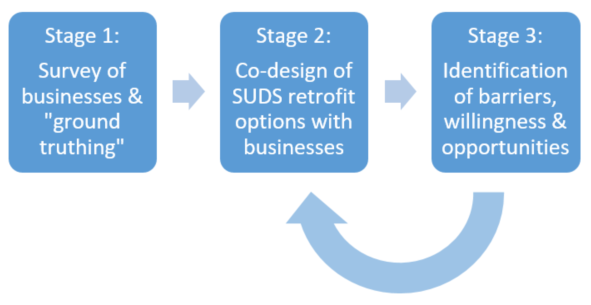
The research methodology involved a multistage investigative process (
Figure 1), with the three main stages outlined below in detail.
Stage 1: Survey of businesses & “ground truthing”. Initially, the principal challenge was to gain access to the individual industrial premises. We issued a survey to the business operators in the industrial estate. The aim of the survey was to gather opinions and raise awareness of the need to better manage stormwater quality. Ground truthing consisted of verifying the existence of any SUDS claimed to be on a particular premises.
Stage 2: Co-design of SUDS retrofit options. Based on the information gained from the survey, SUDS retrofit plans for key business plots were co-designed with the owners.
Stage 3: Identification of barriers, willingness & opportunities. As barriers (e.g., factors such as logistical constraints, cost, and land take) were identified, the SUDS retrofit options were redesigned with these factors in mind as part of the iterative co-design process.
It should be noted that Stages 2 and 3 required several iterations to finalize the detailed case studies presented below. This iterative approach helped to fine-tune the case study material so that it provides a range of examples and sets the agenda for SUDS retrofitting at other premises and industrial estates. The methodological framework presented here is, therefore, relevant to the development of management approaches improving sustainability of urban systems, which is the topic of this special issue.
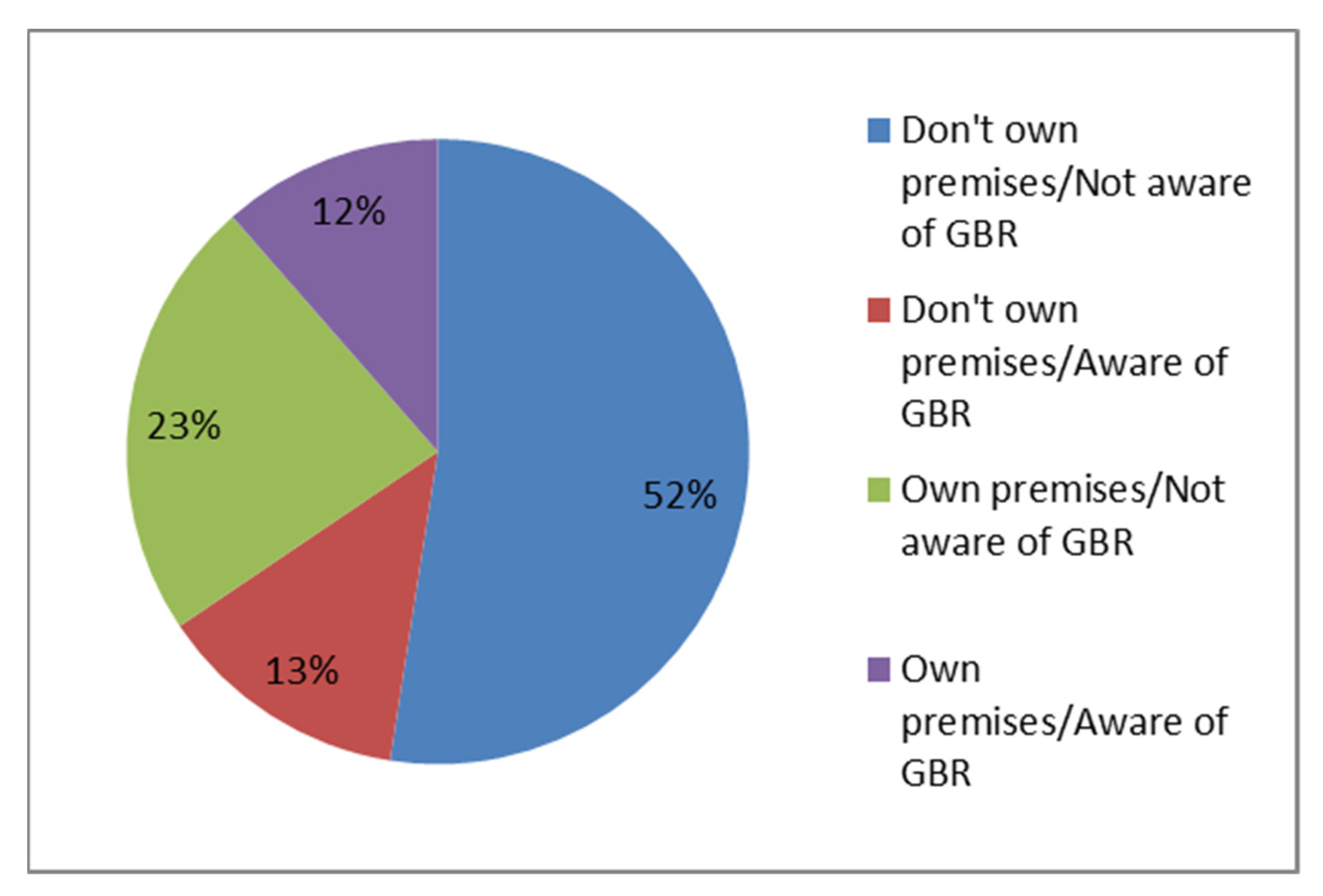
3. Awareness Survey
A questionnaire containing images of various SUDS types was given to the majority of companies on the estate to test their awareness and use of the technology and related legislation. The absolute majority of premises claimed familiarity with at least one specific SUDS type, and many claimed to know about a number of types. However, 10% of all respondents acknowledged their ignorance in that respect (
Figure 2). Furthermore, three-quarters of the surveyed premises acknowledged their ignorance of the term ‘SUDS’, and many of the existing SUDS technologies were unheard of by most premises. Interestingly, the experience of flooding did not appear to be a decisive factor influencing the awareness of SUDS (
Figure 3).
Only a minority of companies (<25%) claimed awareness of the general binding rules (GBR) regulating pollution prevention at the industrial sites in Scotland. Interestingly, among the companies who owned their premises, only a minority were aware of the GBR rules (12% of total premises surveyed), while almost twice as many had never heard of them (
Figure 4).
Many companies also claimed ownership of SUDS, including, e.g., permeable paving, gravel filter drains, and even detention basins (
Table 1). It should be noted, however, that for ground-truth assessments, the companies reporting the presence of multiple types of SUDS on their premises were visited, and on inspection, many of these claims proved false. Specifically, no detention basins, drainage planters, permeable blacktop, grass filter strips, or swales were found by the research team on the premises claiming their ownership. Further multiple errors and instances of confusion were also discovered.
In some cases, conflicting survey responses were received from different businesses in the same commercial unit. Even though all premises in some units had permeable block-paved surfaces, only a fraction of these businesses reported this accurately in the survey. Others incorrectly reported that the roads had a permeable blacktop. In addition, there were spurious claims related to drains, with gravel strips around the buildings being misidentified as SUDS drains. This shows that far more effective sector engagement to educate people about SUDS is required.
Frequent confusions, notwithstanding permeable paving, proved to be the most encountered. In some recently re-developed areas, ubiquitous SuDS technology was used. It appears that SUDS is the “go-to” drainage technology used for compliance with the SEPA requirements in new developments. It should be noted, however, that the permeable pavements in car parks were typically served by conventional tarmac roads and driveways. Furthermore, in many cases, there was evidence of blockages and poor maintenance. Hence, such a ‘tick-the-box’ approach may appear to be compliant with pollution prevention legislation, but provides little in terms of real environmental benefits.
4. Case Study 1—Company A
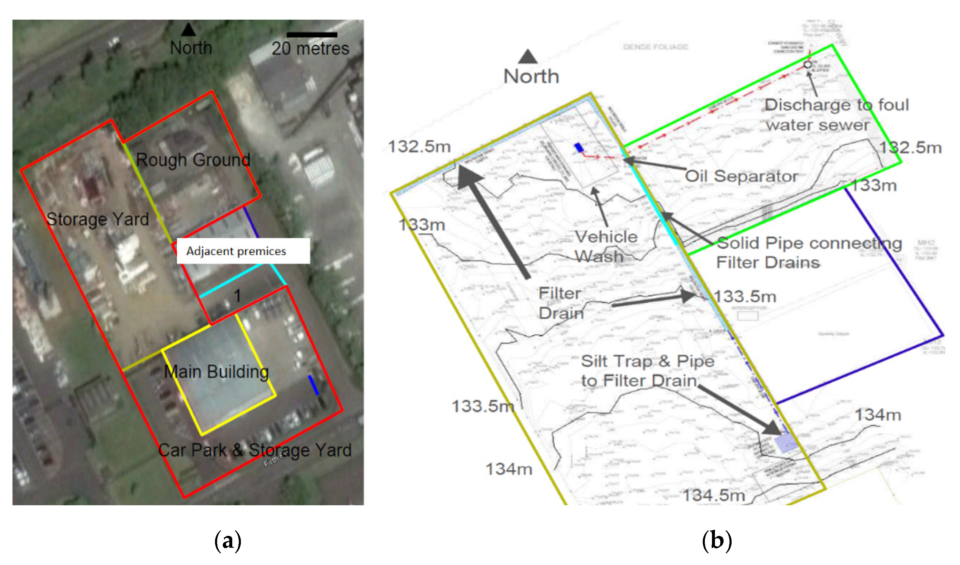
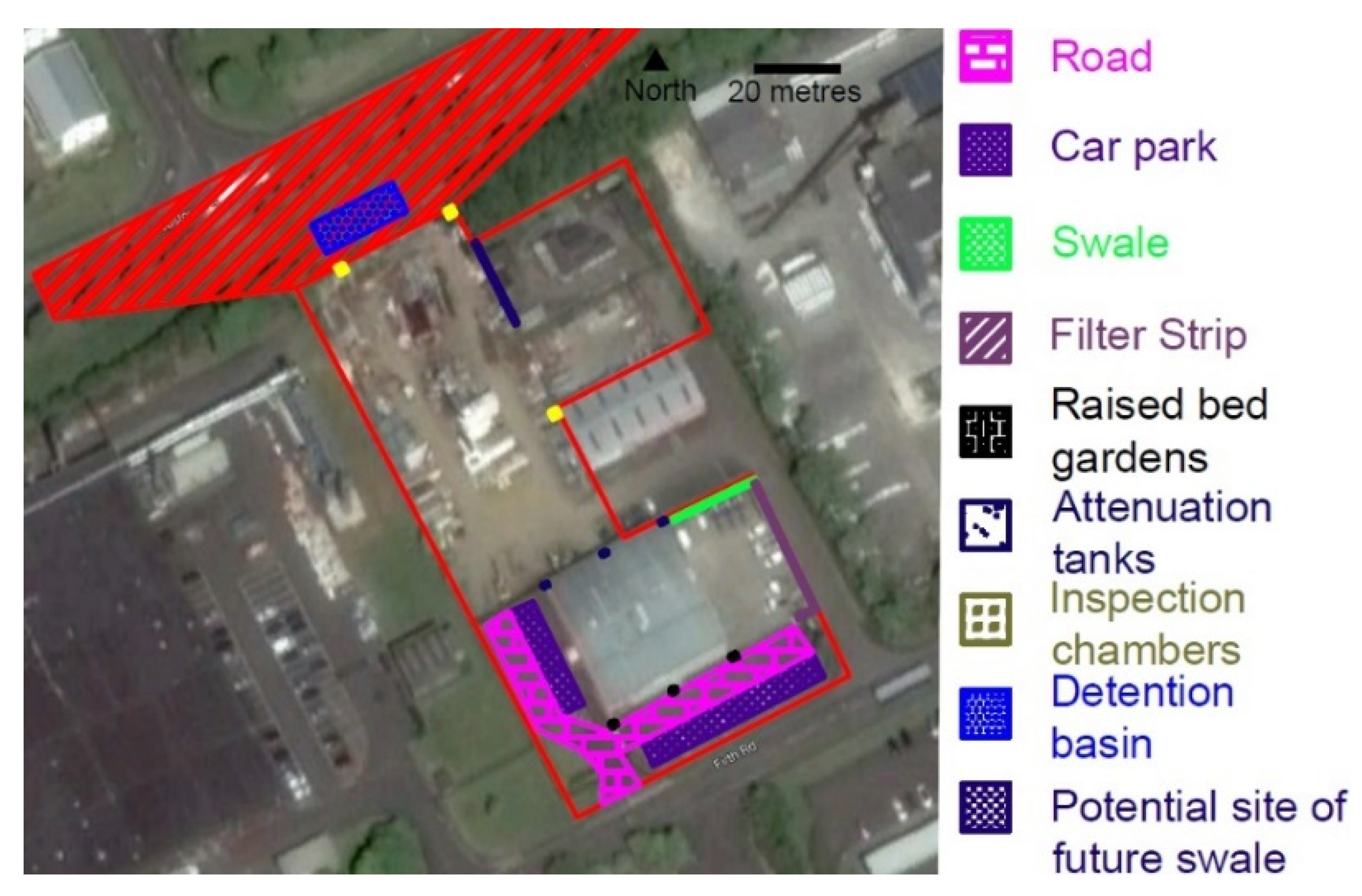
Company A is a medium-sized enterprise which supplies vehicles to the construction industry. The vehicles are large, heavy plant equipment that are leased out to contractors. The vehicles are cleaned by contractors prior to their return and undergo a thorough clean onsite at a wash area. Following this, they undergo servicing at the main building prior to rehire (see
Figure 5 for the layout of the premises).
4.1. Current Drainage System and Availability of Green Space
The premises are drained on a separate system, with separate sewer pipes for the surface water runoff and the foul drainage (including any trade effluents). Surface runoff drains to the local watercourse (via a small treatment wetland serving the estate), and foul drainage goes to the wastewater treatment plant serving the district.
The road surfaces and car park currently comprise regular impermeable paving (
Table SA1). There have been no reports of serious flooding, but some standing water has been reported on the road surface during previous storm events, although it does drain away over time and is not present indefinitely. The most likely reason for this occurrence of surface water is a speed bump in place between the water and the grate preventing adequate draining.
The delivery yard is a simple concrete apron that is used for vehicle and equipment storage. Whereas there was a lot of equipment and supplies at the time of the research team visits, it did not seem as though the material was discarded or neglected. However, the presence of vehicles, both fleet and heavy plant, is potentially an issue due to the possibility of fluid leaks or spills. This risk of contamination is linked to the proximity to the nearby drainage inlet and the lack of any barrier between it and the runoff from the delivery yard.
The roof is drained by means of downpipes at the north and south side of the main building, with forms of potential contamination such as leaves, settled airborne dust, and grit. The risk of pollution from these substances is very low if well maintained.
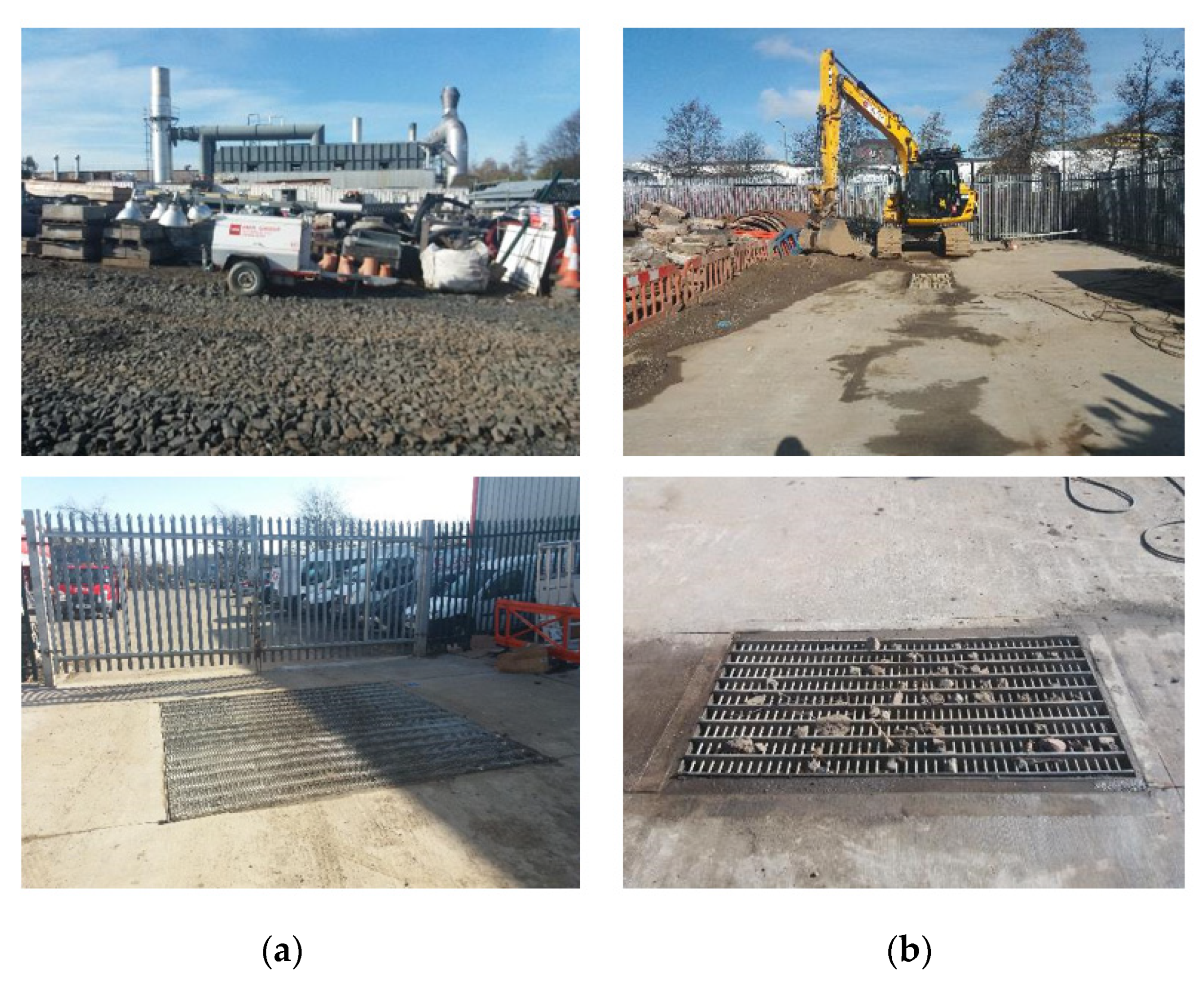
A large storage yard holds a significant amount of equipment and supplies (
Figure 6). When Company A first took possession of the site, it was a grassed area, but the grass and topsoil were removed and replaced with crushed stone/rubble to provide a sturdier surface for the heavy plant equipment being stored in the yard. The ground surface here contains traces of oil, possibly from the vehicles being loaded/unloaded at the entrance. Another pollution source here is a vehicle wash area located at the northeast corner of the yard.
The NE corner of the site (hereafter ‘Rough Ground’) is currently unused. It has various debris, including a derelict office, and is covered by untended wild vegetation. There are no plans to develop or otherwise utilize this area in the near future. There is also some green space at the northern end of the site, but this is outside the boundaries of Company A. In addition, there are also a couple of green spaces available within the site boundaries. First, there is a strip of grass (20 × 1.95 m), adjacent to the delivery yard. Second, there is an area of green space on the western side adjacent to the ‘main entrance.’ However, the size of that green space is likely to be too small, and the required excavations could be quite large and would need to be disposed of properly if not reused on site. Hence, this space may not be suitable for construction of a SUDS feature.
4.2. Sustainable Drainage Systems
Figure 5 shows the location and type of existing features that are relevant to drainage and pollution control. The existing measures are discussed first. Following this, suggestions for potential further SUDS features that could be incorporated into the current system are introduced. These proposed measures are designed to work in conjunction with the current drainage of the site and/or reduce the potential of contamination of the groundwater or sewer network.
The silt trap is located at the entrance to the storage yard (
Figure 6). The plant, vehicles, and equipment are loaded and unloaded in this area. The silt trap is in place so that any mud/grit/fluids from the loading/unloading activities are washed into this feature rather than being washed into the sewer network. Every 6 months, the solids must be emptied for the pit to maintain its available volume for the settlement of solid particles.
The outlet from the silt trap leads to the filter drains, which run the length of the storage yard along the fence, separating Company A from the neighboring premises. The filter drains are constructed so that there is a height difference between the bottom of the trench and the perforated pipe. The pipe sits on bedding material rather than directly on the ground. The reasons for this design are described below.
During smaller rainfall events, the water naturally drains through the bottom of the trench. During more intense rainfall events, there is the possibility that the ground cannot drain quickly enough. In this case, the water rises higher in the trench. Upon reaching the pipe, water will enter via perforations in the base and travel along its length to where it can drain.
When the filter drains were initially constructed, there was a gap in the drain. This gap occurred where the rough ground met the storage yard. This was remedied by the installation of a solid pipe connecting the two filter drains together. This connection is shown by the turquoise line in
Figure 5.
The vehicle wash area (
Figure 6) is a concrete slab that slopes toward a drain in the center. This prevents water contaminated by detergents from running onto the natural ground. This drain leads to an oil separator where any detergents are contained, allowing the water to discharge to the foul sewer shared by the neighboring company.
4.2.1. Potential Solutions
The techniques considered for retrofitting were a function of the space available and included grass swales, permeable pavement, a grass filter strip, a small detention basin, rainwater attenuation tanks, a raised bed raingarden, and simple measures, such as oil absorbent bags in manhole chambers.
Road Surfaces and Car Park
The road surface could be replaced with permeable paving, or porous asphalt (PA), but the new surface may be susceptible to crushing from heavy vehicles (in which case, the surface could not be used). Permeable block paving (PBP) could be used on the car parking spaces. A percolation test would be advisable to ensure adequate rates of drainage before the construction of a replacement surface of PA. The analysis below considers three paving options involving different combinations of permeable asphalt (PA) and permeable block paving (PBP) used in our previous studies [
26].
Delivery Yard
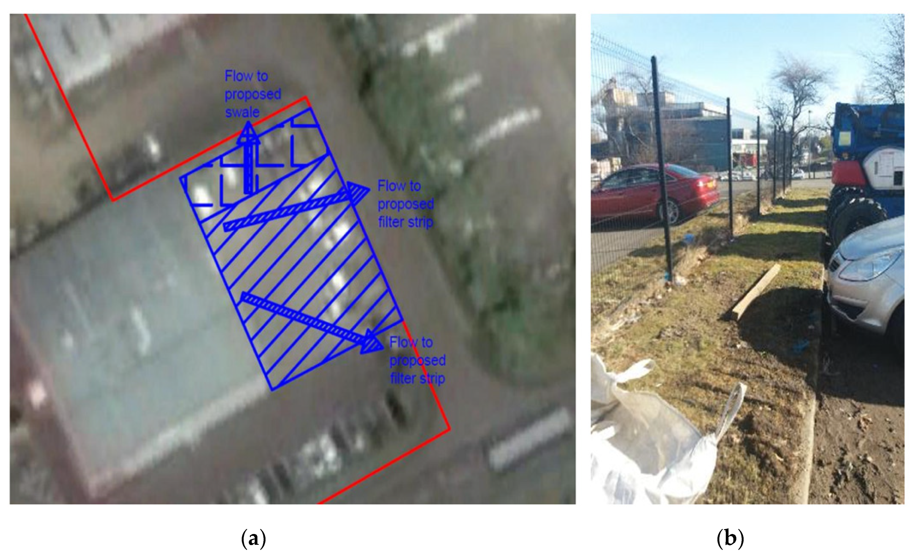
During the site visit, a hose was used to water the slab, and the direction of flow was observed to determine the flow of water on the apron. The diagram in
Figure 7 shows how the water flowed from the north area to the green space while the remainder moved east or south to the sewer grates.
This simple test shows that it would be useful to create a swale on the green space. The delivery yard has a kerb along its length that would have to be removed or modified in such a way to provide entry points for the water.
Figure 7 shows the strip of green space which could be modified into a swale. It would also be prudent to create a filter strip (total length of 36 m) along the east and south side of the delivery yard to contain contaminants before water enters the sewer network. The costs of the filter strip would be around GBP 2–GBP 4/m
2 according to 2007 values [
27].
For filter strips, the SUDS Manual [
6] specifies a minimum topsoil depth of 0.15 m and a minimum engineered soil depth of 0.3 m for a minimum depth of 0.45 m. However, excavation may be needed to reach a subsurface level with sufficient infiltration rates. Because of this, the construction costs of an excavation [
28] were added for a depth of 1.5 m. This depth would be subject to change following a full assessment of the ground conditions and effects on road performance. Hence, the resulting costings are rather approximate.
Roof
The roof has been split into two halves that have three downpipes leading from each side. As recommended in similar situations by a previous study [
26], the use of attenuation tanks and raised rain gardens would provide a method of runoff attenuation.
For Company A, using raised raingardens on the south side of the building could provide an aesthetic feature. Attenuation tanks are recommended on the north side of the building, where the downpipes are placed behind a barrier which would need to be removed. The tanks require less maintenance due to self-regulation by means of an outflow regulator, thus reducing the need for access in the case that the barrier needs to be reinstalled.
Storage Yard
The storage yard is the largest section of the site. When looking at this area, the point of highest elevation will be looked at first before moving downhill.
The silt trap, as described previously, is at storage yard entrance. One suggestion for this feature is the addition of an absorbent oil sock. This would absorb any oil that is washed into the silt trap, as it likely currently flows into the filter drains and down into the ground.
The filter drain runs along the east and north side of the storage yard. Because of the difference in elevation, it is suggested that oil may infiltrate the ground and travel down toward the filter drains. Because of this possibility, it would be prudent to construct the inspection chambers equipped with oil booms. This would allow a quick inspection of the boom to see if any oil has infiltrated from further up the site. Three places were suggested for the inspection chambers, as shown in
Figure 8.
These inspection chambers will be 0.6 m deep, as this is the reported depth of the filter drains onsite. This will allow the oil boom to reach the bottom of both sides of the filter drain without interference from the perforated pipe.
To deal with any contamination that may result from the oil drums, a collapsible oil bund should be used if the drums cannot be taken directly into the main building. The collapsible bund can be stored away securely when not needed. Hence, there would be no interruption in the day-to-day vehicle operations at the yard entrance, and the containment of possible oil spills and leaks would be ensured.
Runoff from the vehicle wash at the bottom of the site is dealt with by the oil separator. However, the discharge from a vehicle wash may emulsify the contaminants in the oil interceptor. Research has shown that oil/detergent mixes are more toxic than each substance separately [
29,
30]. Hence, ideally, the vehicle wash should be drained to the foul sewer, subject to an agreement with the water utility and any conditions they may require.
4.2.2. Additional Considerations
The green space available on Company A’s property is quite small, limiting what can be constructed. As mentioned above, a small swale with optional filter strips could be created to serve the delivery yard. It should also be noted that the rough ground has not been fully developed. Preserving the land next to the current filter drain for a swale could provide additional mitigation should the rough ground ever be developed. This could be used to future proof the site for further development.
There is a large area of green space to the north of the site between Company A and the main road through the industrial estate. The local council or developer may provide funding for some of this scheme if a detention basin on this space was proposed. It is possible that a detention basin on the green space that would serve solely Company A would not be given permission for construction. This basin would, therefore, have to serve the public road in addition to the Company A site.
The detention basin would provide attenuation and trap contaminants from a busy main road through the industrial estate, as well as the potential contamination from the heavy vehicles and material storage on Company A’s property. That would be particularly useful during high-precipitation events.
Figure 8 shows the additional catchment for the proposed detention basin, which is approximately 3110m
2. This catchment size was chosen to double the area of the Company A storage yard. This will provide an estimate for the basin included in the final costs. It is assumed that the water will run into the detention basin from the road and some of the permeable area. This size is an approximation, and a survey of the area to determine the fall of the road would be needed to delineate a more accurate catchment.
4.3. Size and Cost of SUDS Retrofits
The site plan with all the recommended options is given in
Figure 8. Technical details of the proposed SUDS retrofits and the associated logistics are given in
Supplementary Materials A (SA). The comparison of the available and required storage volumes, and the estimates of the resulting costs are presented below.
4.3.1. Storage Volumes
The total available attenuation storage for the Company A site is given in
Table 2, which demonstrates the storage for the specific features including a new detention basin serving Company A and the adjacent road.
The required storage volume needed to cope with the storm events of different return periods is given in
Table 3 for the impermeable area of the Company A site (3110 m
2 from the site and 3110 m
2 from the additional catchment area). If the additional catchment is considered, the minimum storage volume is not sufficient to provide storage for the 30-year RP storm. The additional cost for a bigger detention basin is given in the next section.
4.3.2. Estimated Costs
Table 4 presents the costs of the recommended features for the roof and the two yards. This table has the detention basin as an option. It should also be noted that the costs given for the attenuation tanks and raised raingardens are for the features only. These costs do not include delivery or installation/set-up.
The calculations of cost estimates are based on the unit area costs of GBP 45.89/m
2 and GBP 68.01/m
2 for PA and PBP, respectively. All the unit costs are as described by the authors of [
27] but adjusted to 2020 costs using the Bank of England Inflation Calculator (
https://www.bankofengland.co.uk/monetary-policy/inflation/inflation-calculator, accessed 12 July 2021). The additional cost (i.e., to the cost given in
Table 4) listed for the larger detention basin serving Company A and the additional catchment is presented in
Table 5.
Table 6 presents the amended cost, including the larger required basin.
4.4. Summary of Recommendations for Company A Case Study
The estimated total costs of implementing the minimum features within the boundaries of the Company A site start at less than GBP 33,000 (
Table 6), although installing only the features relating to the roof would provide attenuation for a large runoff area. If the council and/or developer chose to invest in the detention basin, the costs could potentially reach as high as GBP 80,500 (
Table 6). However, with funding from the council/developer, these costs could be offset.
As it stands, there are SUDS already present onsite providing some measure of surface water management. Whereas these methods do not manage runoff from the roof and road/car park areas, the filter drain does serve the storage yard, the single largest area on site. One issue that needs to be addressed is the potential for oil contamination of the storage yard. Although the oil is only stored there upon delivery before being moved, it is recommended that an oil bund is used. The proposed oil bund could address the storage of drums with minimal cost and manage accidental spillages. The vehicle and equipment spillages can be minimized by staying up to date with any maintenance and service requirements.
5. Case Study 2—Company B
The business operations in this case study site forge metal components for the petrochemical and aeronautical industries. The range of products produced onsite includes jet engine shafts, valves able to function under pressure for oil and gas industries, seamless extruded metal pipes, and other high-specification products. Forging is by heat and pressure. The site has the largest multi-ram hydraulic press in Europe (30,000 tones), as well as a smaller unit (9000 tones).
The premises of Company B are a significant industrial estate, with process areas, loading/unloading areas, outdoor and indoor storage of materials, and access roads. In addition, there are heavy vehicles, including cars and other vehicles, moving in and out of the site. Potentially toxic materials are involved, albeit carried in small containers. The metal processing chemicals used include hydrogen fluoride (HF), nitric acid (HNO3), and ferric chloride (FeCl3)—all brought onsite in 30-liter individual vessels. Caustic is also used and brought onsite in standard 1000-liter vessels. Cutting oils and lubrication oils are used in machining work, and waste oil is also generated onsite. Housekeeping measures range from bunds to lockable cabinets.
5.1. Site Drainage
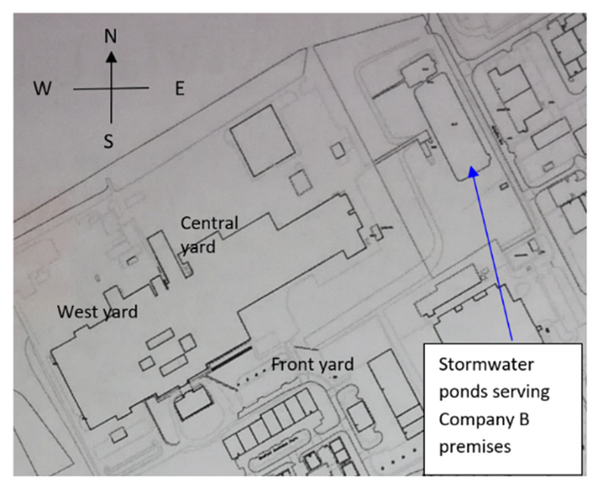
The site (
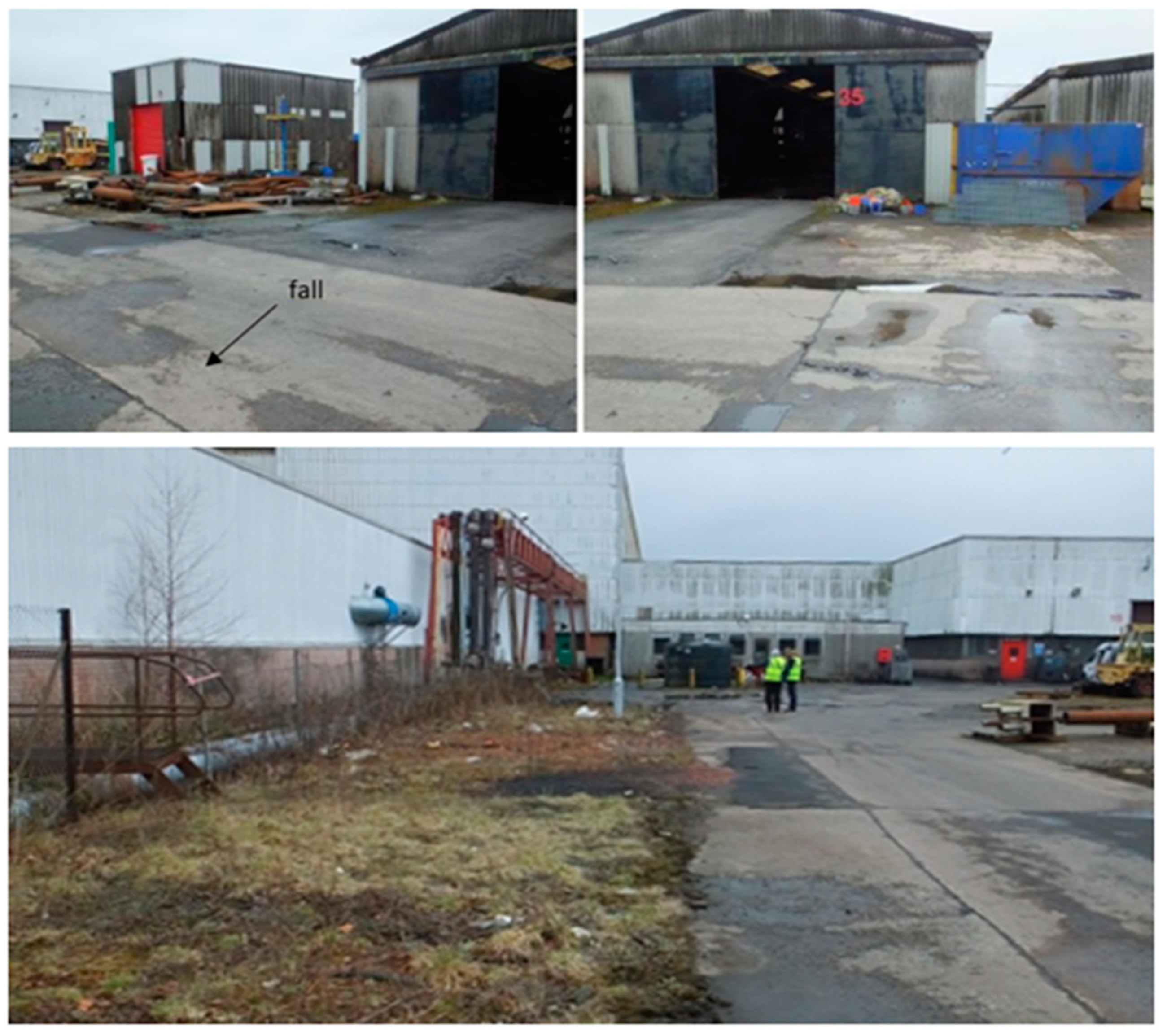
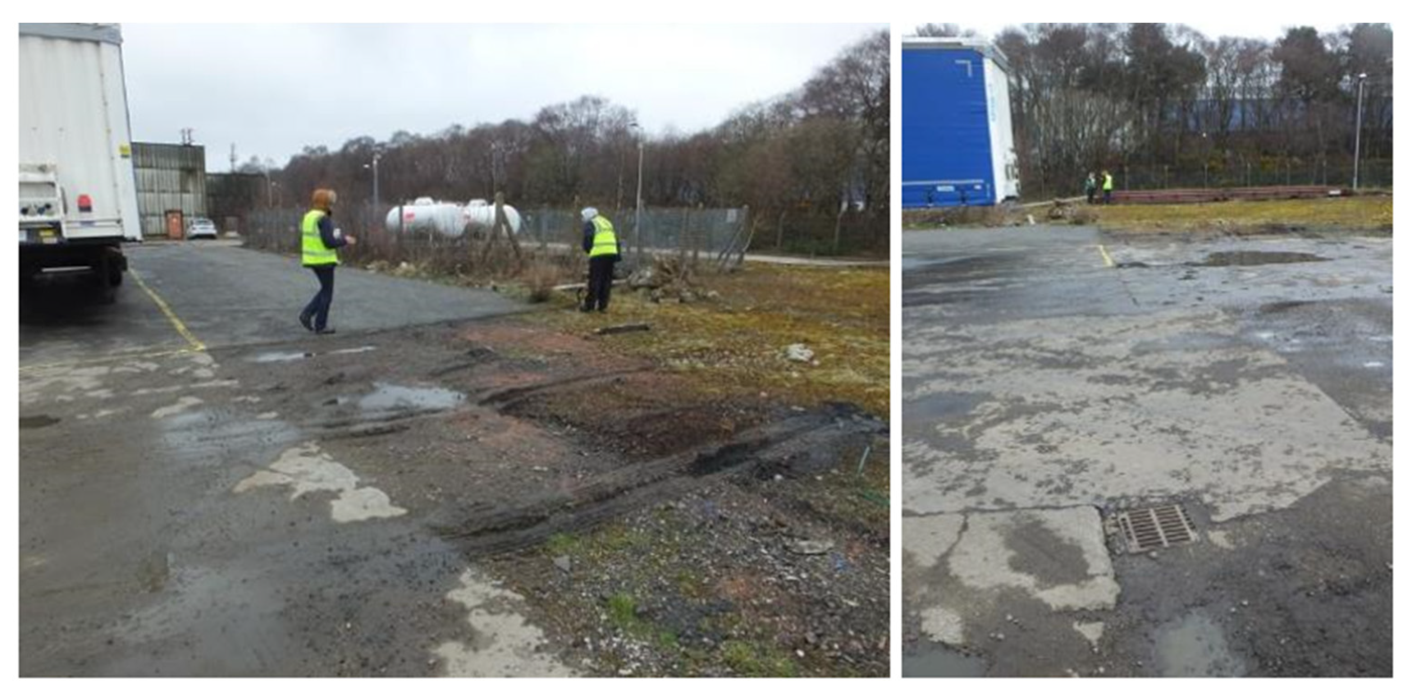
Figure 9) is drained by a separate sewer system, with surface pipes draining most of the site into a stormwater pond, and foul sewers draining into the Scottish Water sewer network. There is an effluent treatment facility which takes trade effluent and pre-treats it prior to discharge into the foul sewer under license from Scottish Water. The treatment comprises an oil interception and pH adjustment. The yard areas include extensive, clearly contaminated surfaces liable to wash-off in wet weather (
Figure 10).
There are multiple diffuse source pollution risks for contaminated drainage in the west yard area, and the quality of runoff is evident from the pools of surface water on the impervious surfaces (
Figure 11).
The buildings along the boundary of the west yard area include an oil handling area. An integrally bunded tank is bounded by a slotted drain, forming a rectangular catchment area. Nonetheless, some oil contaminated runoff inevitably escapes to contaminate that locality. In the same area, a chemicals store is located (a cabinet-style lockable storage unit), in which potentially polluting chemicals are stored. Some containers, however, are too large for the unit (
Figure 10).
As well as the storage areas, that part of the west yard is also a diffuse pollution hotspot for other contaminants. Traces of oily swarf are present on the ground, as well as other visible signs of contamination.
On the opposite side of the roadway that forms the eastern boundary of the west yard, there are storage buildings that contribute to spillage risks in that hotspot area of the site (
Figure 11). A strip of unmade ground opposite the line of buildings is traversed by pipelines but has limited use except as a very limited greenspace in the extensive areas of buildings and concrete yards. It is well positioned to be modified to create a grass swale (see section below). It may be difficult to excavate, with indications of old gravel and construction debris. However, the fall across and along the road is suitable. The fall along the road favors a pollution control swale, as runoff drains from the oil storage tank down past the miscellaneous buildings (
Figure 11). The camber on the road faces the potential swale site.
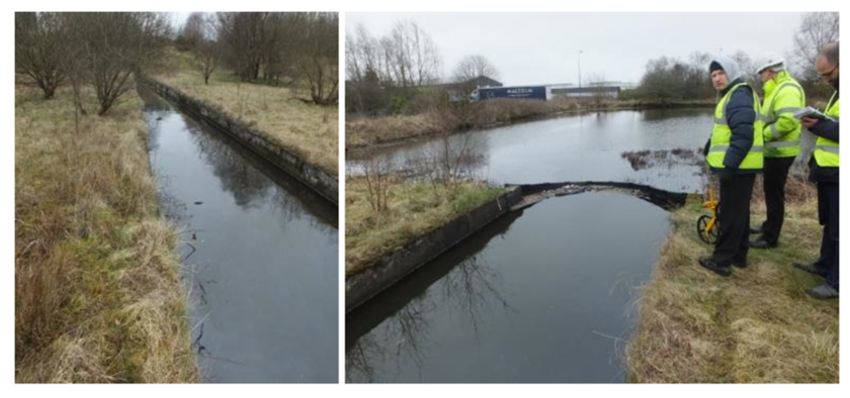
The top road is the boundary of the site to the north. Behind the boundary fence, the rising ground is covered in trees (a narrow boundary plantation). The eastern edge of the site drops down to the ponds along the eastern boundary (see
Figure 9). More extensive impervious areas with obvious surface contamination nearby are also alongside some unmade ground (
Figure 12), but the fall for drainage is not ideal for using those areas (although not impossible).
In the northeast corner of the site, there is another storage area for chemicals and waste (
Figure 10) with a surface water gully in the center.
At the front yard, there is car parking, as well as area where hot metal unfinished products are brought outside to cool before further work. Surface water puddles in that area were oil-contaminated and darkly discolored. This area may not be suitable for discharge to a surface water drainage system, and analyses and contaminated ground assessments are pre-requisites for such considerations. The best option might be a sealed sump for the routine removal of contaminated runoff as part of the indoor factory floor cleaning and suction to remove contaminated water. Creating an improved or new drainage pathway here seems undesirable.
5.2. Existing SUDS at Company B
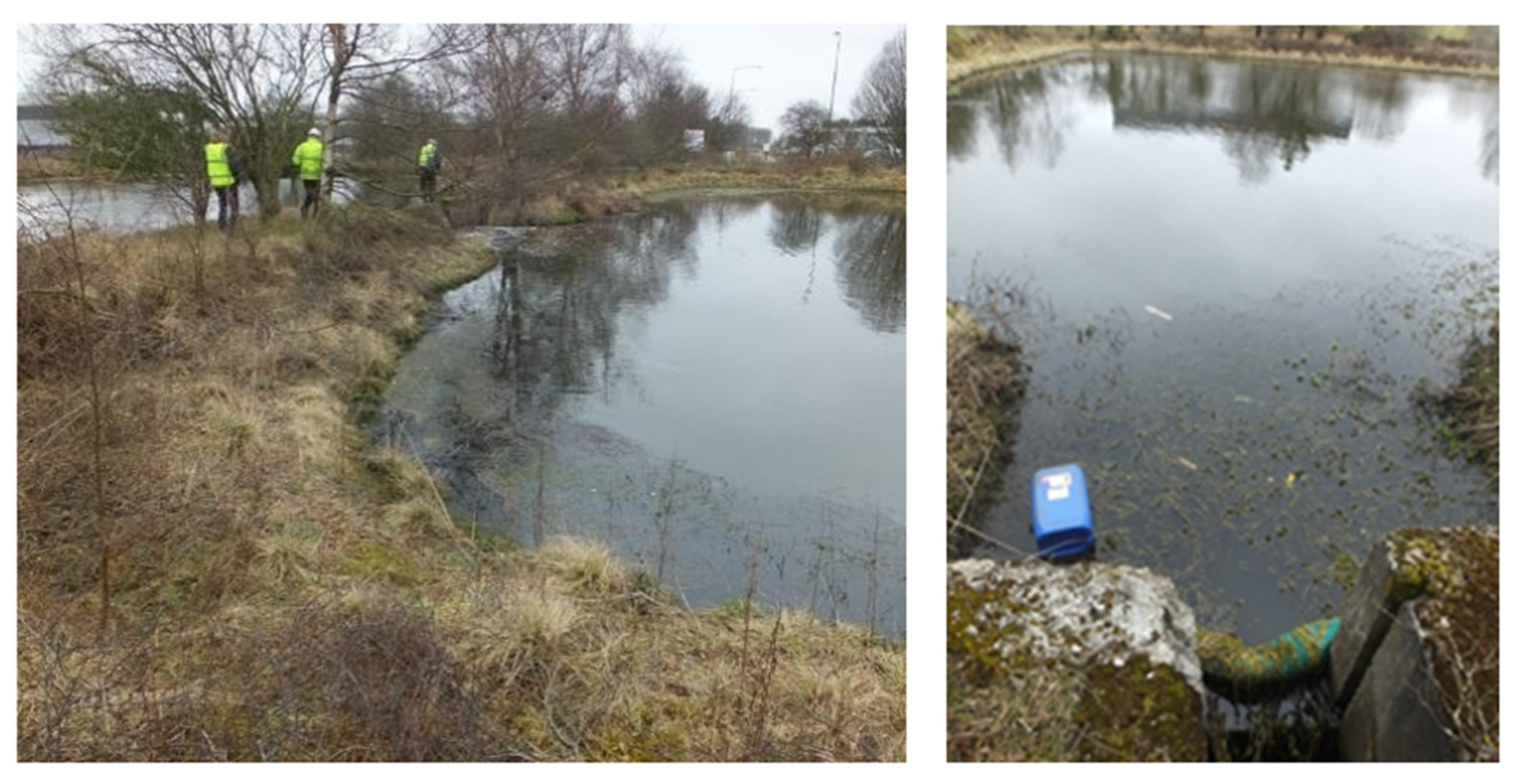
Company B has a lagoon for stormwater treatment (
Figure 9). The lagoon is protected by a broad inlet channel, which has an oil boom at its outlet into a primary pond that serves as a sediment forebay to capture heavier particulates in suspension (
Figure 13). The overflow from that pond discharges into a large rectangular pond, from which good-quality water is abstracted for use in the factory. Excess water discharges to an outlet drain (
Figure 14) and onto the receiving water course.
The inflow to the ponds includes recycled process water used for cooling and returned flow from the abstraction from the pond. The company fills up the process water using the main supply as necessary.
Assuming an approximate mean depth of 1.5 m for the forebay and 1.75 m for the main pond, the total volume of the primary pool and the main pond can be estimated as ~9700 m
3. Given that the surface area of the Company B premises is ~160,000 m
2, of which the proportion of impervious surface in the area draining to the treatment ponds is approximately 90%, this pond could easily accommodate the treatment volume specified for such circumstances in SUDS guidance [
31]. This compares favorably with the total design volume of the pre-SUDS stormwater wetland for the watercourse receiving stormwater from the whole industrial estate on which the Company B premises are located (including the pond/forebay wetland that is only ~3800 m
3).
5.3. SUDS Retrofits for Company B
Most of the site drains into the end-of-pipe SUDS pond. The SUDS pond appears to be a well-designed feature. It also has the benefit of an open channel for tens of meters, complete with an oil boom, prior to a sediment forebay pond that is well positioned at the head of the rectangular main pond. It also appears large enough to balance the inflows and minimize any contribution to flood risk downstream.
The case for retrofits at Company B is to protect the ponds, which represent a valuable water resource for the company, as well as the environment, from an excess of contamination from activities around the site. In particular, the suggested measures would provide three categories of benefits:
Daily routine first level of clean-up around the identified sources of point and diffuse pollution
Enhanced provision of greenspace with subsequent benefits for its ecosystem services
Planning for contingency (for efficient handling of pollution from leaks, spills and accidents)
In respect of the latter benefit, there is an important approach road (typically only modestly contaminated, but a potential hazard nonetheless) which does not drain to the ponds. Therefore, this road would be the environmental priority for a retrofit.
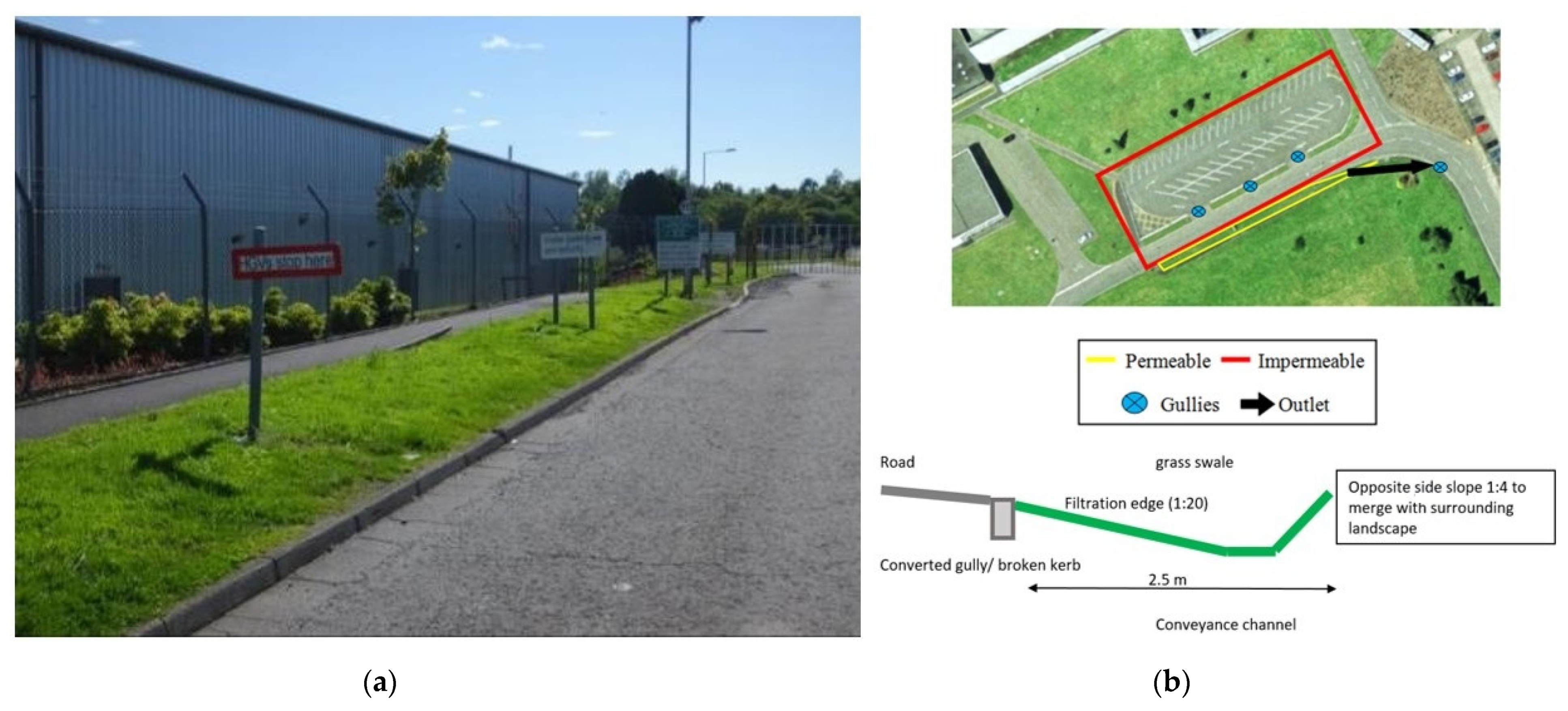
5.3.1. Grass Swale for Approach Road
Surface water drainage from the approach road and the adjacent extensive visitor car park discharges via a limited number of road gullies into a different branch of the drainage network serving the estate. It does not drain into the Company B ponds (see
Figure SB1). Thus, there is currently no treatment or pollution risk management provision for any accidents in that area. All access to the site is along that road. An inflow of lorries carries containers of acid and caustic, detergents, and other materials (as well as diesel fuel—the ubiquitous pollutant for every lorry irrespective of payload). A SUDS retrofit as a contingency planning provision to allow quick and easy intervention in the event of an accident is desirable.
There is a length of grass verge in the ownership of the company which could be converted into a swale. It could be designed to be a biodiversity feature and function as such for day-to-day purposes, treating the modest contamination likely to arise from that road and car park area without difficulty. However, in the event of a rare but severe pollution incident (comparable infrequent risk to large storm events, which also govern swale design), the swale would prevent pollution impacts beyond the company premises, including hazards to third parties working in the drainage network on the estate or at the Scottish Water treatment wetland on the receiving water course.
The dimensions of the grass verge for the conversion to a source control swale are given in
Table SB1, while the layout of the proposed feature is presented in
Figure 15. It should be noted, however, that the principal design challenges for retrofitting the grass swales are:
How to introduce runoff into the swale to achieve filtration through the grass sides slopes and sedimentation in the base channel
How to exclude vehicles, especially large trucks and lorries on an industrial estate, from incursions into the swale
How to achieve effective outlet flow control to detain outflows and allow sedimentation in the swale, which is equally important (but sometimes approached poorly).
The recommended design involves removing the kerbs and laying them flat at a 45-degree angle to meet the grass surface at a new lower soil and grass level. This would overcome the downfall of many swales in not preventing the grass levels from growing higher than road surface level (see the case study of Pittner et al. in [
7]).
Vehicle exclusion would be by large intermittent barriers such as posts or rocks. There are already several large signs, so the verge is already a recognized, prominent feature by drivers. An alternative barrier would be a low evergreen hedge (a linear drainage planter using free-draining soil) to serve the same purpose of the conventional road-edge kerb, but also enhance biofiltration [
32]. Whereas this alternative barrier would work for cars and vans, it may not be effective for larger vehicles.
Outflow should be a two-stage structure at the lower end of the swale: a high-level horizontal grill in the event of a major rainstorm, covering an outlet chamber with a base-level entry from the swale which can easily be blocked by a piece of turf in the event of a rare but serious incident. Routine maintenance would be required to keep that restricted flow path clear in normal circumstances. Periodic grass cutting would be the only other required routine maintenance (but less frequent than that needed for the existing grass verge).
5.3.2. Grass Swales for Areas within the Factory
Two areas were identified as secondary priorities for retrofits: inside the factory fenced area and draining to the SUDS ponds. The potential swale to help manage pollution risks at the road and oil/chemical handling areas would assist in protecting the valuable water resource of the ponds at the factory by achieving capture and treatment at the source. It may also help improve the day-to-day practices and care in handling the potential pollutants. The other suitable area is along the western boundary serving the road trafficked by all the large vehicles bringing chemicals into the factory. It should be noted that soil and vegetation removed from the grass verge while constructing the swale for the approach road (see above) could be efficiently used in both situations.
Tables SB2 and SB3 and Figure SB2 demonstrate appropriate design details and dimensions for this type of swale based on the measurements at the site.
5.3.3. Other Possibilities at Company B
The visitor car park (
Figure SB3) is served by several road gullies located in the tarmac at the downhill part of the car park. They are close to some crash barriers, which demarcate the car park from the road. It should be possible to retrofit some biofiltration planters (in-ground raingardens, e.g., tree-pits) to divert the flows from the gullies. The planters could be drained in a new pipe back into the drainage system after providing treatment and attenuation. This would provide treatment for an additional area of 2306 m
2, which currently drains to the local watercourse without abatement.
Alternatively, a carefully designed swale (see above) may be able to accept runoff from that car parking area and simply seal off the gullies. The fall is in the correct direction to reach the swale, but the impervious area draining to it is large.
Similarly, there are extensive (but relatively uncontaminated or lightly contaminated) areas with grass margins within the catchment area of the surface water drains which do not pass to the ponds. There are two options for retrofitting these areas:
Option 2 would provide treatment for an additional area of 2306 m
2, which currently drains to the local water course without treatment (see
Figure 15, left-hand side of the plan).
It should also be noted that there are extensive grass landscapes beyond the impervious front strip, sloping down to the approach road outside the boundary fence. If and when the company has sufficient resources and other reasons to regrade and restore the condition of the front access perimeter road and car parking, then it would be sensible to determine if such a project could divert the runoff into those grass areas, perhaps with a collection drain to collect excess runoff for slower seepage rate into the existing drainage network. Strictly horizontal levels, for even flow distribution, are essential for a grass filter strip. If it is difficult to achieve horizontal levels, then it might be better to drain parts of the area to in-ground rain gardens within the grass space (
Figure SB4).
6. Discussion
The need to address the pollution problems in rivers and respond to the climate emergency comes with significant challenges. Green and Blue-Green Infrastructure will be at the heart of the response, and there are already many initiatives showing how it can be retrofitted to residential and commercial developments [
33]. However, little consideration has been given to industrial areas. Industrial areas pose challenges due to the potentially higher pollutant loads and increased complexity regarding who receives the multiple benefits derived from the Green Infrastructure [
34].
6.1. Importance of Different Approaches
It is widely acknowledged that decentralized SUDS and BGI solutions provide good options for the treatment of stormwater runoff [
35]. Previous studies have shown how ‘end-of-pipe’ pollution control measures, such as wetlands [
25,
36], can be complemented by ‘source-control’ measures, such as swales and permeable pavement [
37]. Such specific measures are often considered in isolation but would best function in concert. The current paper also provides practical examples in that respect and considers a range of various available options and their feasibility. Crucially, the costs for case study A are provided alongside the logistics, technical feasibility, and the resulting environmental benefits. These estimates should be treated as approximate, but are nevertheless indicative of the potential costs likely to arise from the retrofitting of the considered SUDS features.
It should be noted that the traditional ‘containment’ measures are indispensable, and often effective and practicable. They should, therefore, be the first line of defense wherever chemical handling operations occur, which is exemplified here in both case studies and was particularly relevant for Company B. However, the contamination of surface runoff by diffuse pollution is inevitable. Hence, the application of measures such as filter drains, swales, grass filter strips, and SUDS ponds, should become routine, and the case studies presented here provide a number of practical recommendations in that regard.
6.2. Importance of the Participatory Co-Design Process
The importance of participatory processes and accounting for the local conditions is generally accepted both in relation to urban water management, particularly the mitigation of the potential consequences of flooding, and surface water pollution [
9,
38,
39,
40,
41]. Involvement of stakeholder practitioners in the design processes is crucial, as without it, the prospective retrofits are unlikely to succeed. In particular, co-designing the solutions together with the stakeholders helps to identify, and subsequently obviate, a range of potential logistical constraints related, e.g., to local conditions, peculiarities of technological processes, the availability of infrastructure, future plans, and the views of the senior management. Techniques such as discussion forums, focus groups, and learning and action alliances (LAAs) have been used to promote stakeholder participation in finding workable solutions for difficult problems related to flooding and water quality issues [
9,
42,
43].
To be viable, the proposed solutions should strive to overcome the challenges of accessibility vs complexity tradeoff [
40]. The prospective retrofit techniques must be affordable, understandable, and reasonably implementable for specific stakeholders while retaining sufficient sophistication to provide sufficient improvements and the benefits sought. This study applied a participatory approach involving iterative consultations for co-designing pollution prevention and innovative mitigation solutions, thus striving to optimize the outcome with respect to affordability, effectiveness, and logistical constraints.
6.3. Applicability of the Methodological Framework to Other Premises and Industrial Estates
Methodologies and case studies concerning the optimization of industrial processes and functioning of urban systems by improving the resilience of infrastructure are among the major themes for this special issue. The presented research has sought to design methodology to address the knowledge gap of practical implementation of ‘source-control’ measures for mitigating polluted runoff from industrial premises by working with businesses in one of Scotland’s largest industrial estates, an area known to contribute to nontrivial water quality problems in a nearby watercourse. It is noteworthy that the setting of the industrial estate, the layout of the premises, and the proposed solutions are typical for many other industrial estates both in the UK and worldwide. The names of the participating companies are not revealed, but the approach used to identify potential SUDS retrofits, assess the logistical feasibility of the proposed solutions, and estimate approximate costs is transferrable to other industrial estates and commercial premises. Hence, the approach and the methodology used in this study are easily applicable elsewhere. In general, the methodological framework developed and applied by this study is directly relevant to the further development of management approaches aiming to improve sustainability in urban systems, which is the topic of this special issue.
6.4. Barriers to Retrofits
The results of our study are broadly in line with previous general research on potential barriers related to the development of BGI and SUDS installations [
8] and provide further important insight in the industrial estate context. Lack of awareness was previously reported to be among the major barriers for the installation of BGI assets in residential areas [
9,
44]. In our research, lack of knowledge related both to SUDS technology and pollution prevention legislation was identified as a major barrier to retrofits in industrial estates. This needs to be tackled urgently by education campaigns.
The very limited awareness of either the legislation or the technology surrounding SUDS suggests that a retrofit program or initiative without the associated education and engagement would, at best, create features destined to be neglected subsequently. It also has implications for the new build and the general use of SUDS. Thus, there is a major need for a sustained engagement and education efforts by all the organizations involved in driving SUDS into routine business.
In addition to the lack of knowledge, this study identified three broad classes of barriers to retrofits: cost, time, and space. More detailed comments and views were identified in the one-to-one dialogue during the initial survey and follow-up visits, in the dialogue with the case study businesses, and through the discussion with the focus group.
It should be noted that industrial estates tend to host companies with widely differing sizes and activities, ranging from office-type work to heavy industrial operations. This study and the previous work [
26] highlighted that businesses were open to considering retrofitting Green Infrastructure once the benefits were explained, and that viable technical solutions are available. Typically, larger businesses who owned their lot were more likely to engage constructively than small operators which rented their facility. Smaller operators understood the benefits, but often saw it as a matter for their landlord. It was noted that some sizable operations had little local capacity to develop or maintain their real estate, and they often deferred to a manager elsewhere where these issues were concerned.
The case studies presented herein deal with a medium-sized company (Company A) and a large company (Company B). Larger businesses appeared more likely to have a corporate policy in place to mitigate the impact of their operations on the environment. These businesses were also more likely to have space within their lot to allocate to retrofits. However, concerns were raised that such an investment would act as a barrier to the business being able to use that space for the future expansion of their operations. It is therefore important that any proposed retrofits should be realistic and take this kind of consideration into account, providing various options such as those proposed in this research.
A detailed survey and extensive communication with businesses demonstrated that the fragmented land ownership in the wider industrial estate was a barrier to some retrofit approaches, particularly the ones which drained more than one lot. A further issue was that many businesses felt that they worked within the guidance set by the environmental regulator and that they paid the water services provider to resolve any drainage issues. Nonetheless, the case studies presented in detail here clearly show that while there are barriers to retrofitting, installing SUDS and Green Infrastructure features is technically and economically feasible. This suggests that progress can be made with the correct incentives.
6.5. Relevance to the BGC Conceptual Framework
Achieving the mitigation of polluted runoff from industrial and housing developments is a prerequisite of sustainable urban growth. It should be noted that most practical actions are often focused on flooding at housing estates, while industrial pollution is mainly addressed in relation to the incidents of acute illegal discharge. It is, however, paramount that chronic diffuse pollution and planning the contingency measures for potential accidents become part of routine management both in the residential and industrial areas. This safeguarding of the runoff quality is one of the central themes for the developing conceptual framework of urban flood management (UFR) in Blue-Green and Sponge Cities [
10,
14,
33]. Our study is very relevant in that respect.
In addition to the improvements in water quality and alleviation of flood risk, the introduction of Green and Blue-Green Infrastructure will lead to further benefits related to such ecosystem services as the amelioration of the local climate, reduction of noise, improvements in air quality, enhancement of the local biodiversity, and positive effects for the human well-being and mental health (see, e.g., [
9] and references therein). In industrial settings, it may also have an indirect positive influence on the employees’ productivity. SUDS/BGI features considered in this paper, such as biodiversity swales [
6], raingardens [
11], and retention ponds [
12,
13,
45], are particularly relevant in that respect. The existing SUDS ponds at Company B provide a valuable example of how BGI installations can be used effectively not only to alleviate the flood risk and mitigate polluted runoff, but also to provide efficient grey water reuse (GWR) and optimize the supply of valuable water resources for technological processes. Further studies should examine the contribution of these ponds to the local biodiversity value, which is expected to be significant based on studies of BGI ponds elsewhere [
11,
12,
13,
46]. Further research should also address the possibilities of increasing GWR through economic and policy instruments using participatory system dynamics modelling [
38,
39], and should examine potential tradeoffs between specific retrofits [
45]. Approaches such as comparative theoretical ecosystem analysis [
47] and tools comparing multiple benefits based on changes in natural capital [
48,
49] will be particularly relevant in that respect.
7. Conclusions
SUDS technology, combining Green Infrastructure with the passive drainage of stormwater, helps to overcome the challenges related to the pollution problems in rivers and respond to the climate emergency by capturing the pollutants present in runoff from the industrial landscape. This paper developed a methodological framework, presented the results of the awareness survey, examined barriers and opportunities, and provided two detailed case studies dealing with potential SUDS retrofits at industrial facilities, assessing the existing control measures and the scope for new ones with the aim to improve pollution management.
First, this study developed a multistage investigative framework structured to facilitate the search for relevant solutions and optimization of their design.
Second, the lack of knowledge related to SUDS and pollution prevention legislation was identified as the major barrier to retrofits, which should be addressed through educational measures. Many proprietors were not familiar with SUDS, and the majority were ignorant of the relevant legislation. Among those who claimed familiarity or ownership of SUDS, many were found to be mistaking.
Third, the co-design approach used to create SUDS retrofit solutions demonstrated that it was possible to work with proprietors to sustainably improve water quality. Whereas many of the design elements consumed space, none impacted the operation of the business.
This study exemplified the potential of SUDS retrofitting to improve pollution management on complex industrial premises. The approach used to identify potential SUDS retrofits, assess the logistical feasibility of the proposed solutions, and estimate approximate costs is transferrable to other industrial and commercial areas. Adaptive, inclusive, and innovative design is key to overcoming physical retrofitting barriers, such as landscape limitations and combining the “end-of-pipe” solution with an effective runoff treatment at the source.
It is recognized that the diversity of business in size, activities, land ownership, and responsibilities in industrial estates may entail a barrier to SUDS retrofitting that needs to be addressed by an awareness campaign, range of solutions, and incentives. Nonetheless, the case studies presented here clearly show that while there are barriers to retrofitting, installing SUDS and Green Infrastructure features is technically and economically feasible. In addition to the improvements in water quality and alleviation of flood risk, a developed Blue-Green Infrastructure network will also contribute a range of further benefits related to the increased biodiversity and amenity values, as well as other ecosystem services.


 ,
, 


