Abstract
To date, the grid-connected solar photovoltaic (PV) system has drawn consideration from researchers and academicians due to the speedy improvement and the declining price of solar panels. The proficiency and dependability of a grid integrated PV system rest mainly on the power conversion unit and the proper controlling mechanism. This paper introduces a novel asymmetric hexagonal-shaped fifteen-level inverter designed to feed a grid-integrated solar PV system. First, it aims to reduce the number of components and thereby decrease the installation space and cost of the multilevel inverter. Moreover, it has a low total blocking voltage (TBV) and total device rating (TDR) and uses few switching devices for generating per level of output voltage. The proposed topology utilizes only eight switching devices for generating fifteen levels at the output, which is lower than conventional multilevel inverter topologies. Here, a low-frequency modulation scheme using the half-height (HH) method generates switching pulses to minimize the complexity. The proposed multilevel inverter topology is also validated through the simulations in the MATLAB SIMULINK environment. The proposed inverter need for filters is illustrated according to different grid codes for integrating PV systems to the grid.
1. Introduction
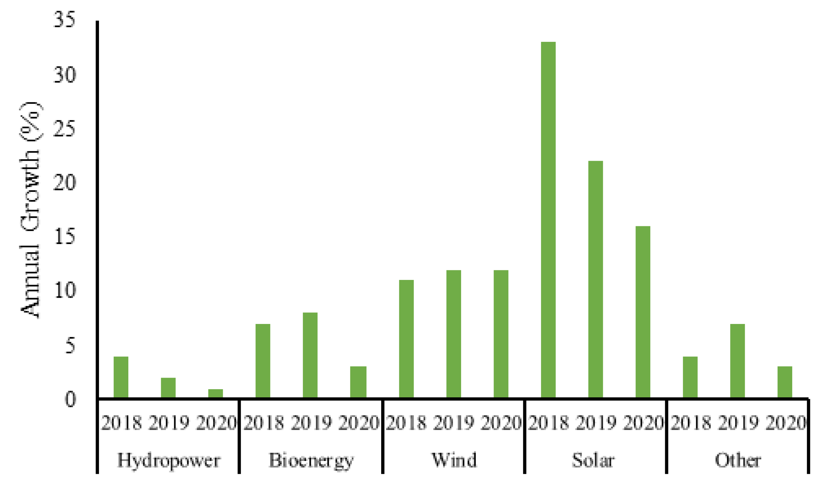
Global energy demand is increasing day by day due to the strong global economic growth and higher heating and cooling demand. Due to the rise in fossil fuel expenditure, humankind is currently facing two critical worldwide crises: the energy crisis and the environmental climate crisis. In recent times, global energy-related carbon dioxide (CO2) emissions grew an estimated 1.7% [1]. For this reason, there is a worldwide focus on renewable energy sources to produce electricity with clean power generation to meet the increasing power demand [2]. Many countries such as Iceland, Costa Rica, Norway and others, are now turning to 100% green energy and showing a high penetration level of renewable energies in their national and regional power grids, as illustrated in Table 1 [3]. Several renewable energy sources such as solar, wind, wave, and geothermal energy are currently available. Among them, solar and wind energy will dominate future power production worldwide, as seen in Figure 1 [3]. Although the preferred renewable source for electricity generation is the solar PV cell, as Figure 1 suggests, surprisingly, the interest in it has decreased steadily while the presence of wind power has grown day by day.

Table 1.
The penetration level of renewable energies in different countries.
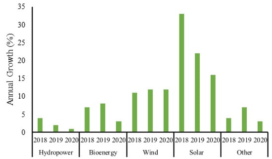
Figure 1.
Annual growth for renewable electricity generation by source, 2018–2020.
Table 1 shows that the world is now moving towards depending on renewable energy completely. The main challenge, however, is to design a system that successfully integrates renewable energies and the power grid. Most renewable sources produce direct current (dc) power, while the power grid runs alternating current (ac). Thus, an inverter system is needed to produce ac power from dc power generated by renewable sources.
The first invented inverter topology applied only to low-level systems, producing square voltage from renewable energy sources [4]. However, the grid required the ac voltage; thus, a filter circuit was needed to convert a square wave into a sinusoidal wave. Moreover, the proposed two-level inverter had a high dv/dt ratio, high total harmonic distortion, poor output voltage quality, minimum conduction, switching losses, etc. [5]. For solving these problems, in 1970, the first multilevel inverter was proposed for generating three levels of output voltage and further designed to n levels of output voltage [6]. The most common multilevel inverter (MLI) topologies are diode clamp multilevel inverter (DC MLI), flying capacitor multilevel inverter (FC MLI) and cascaded H-bridge (CHB) multilevel inverter [7]. Among all topologies, the cascaded multilevel inverters are the most popular because they provide a simple circuit layout and a modular structure and avoid unbalanced capacitor voltage problems [8].
Currently, researchers are focusing on compact weight and cost-effective topologies with fewer semiconductor devices and fewer voltage sources. The cascaded H-bridge topology has failed to attract their attention because it still uses many semiconductor switches and voltage sources. The problem of many voltage sources can be minimized by applying a magnetic link-based isolated transformer; however, it produces more switching losses due to the leakage of the transformer with a low switching frequency [9]. Several reduced switch MLI topologies that have been introduced are mainly of two types: symmetric and asymmetric MLI topologies [10]. The symmetric multilevel inverter contains two parts: the level generation unit and the polarity generation unit. The level generation unit has the same number of voltage sources as the cascaded H-bridge MLI topology, while the polarity generation unit is the full H-bridge configuration. The complete design uses fewer switching devices than conventional DC MLI, FC MLI, and CHB MLI topologies. Although the symmetric multilevel inverter has partially solved the problem of using a large number of semiconductor devices, it still faces the same difficulty as the cascaded multilevel inverter, namely the use of a large number of dc sources [11]. Recently, this problem has been overcome by applying asymmetric MLI configuration. In the asymmetric configuration, different values of voltage sources are used to generate the required voltage level. This configuration uses fewer semiconductor devices and voltage sources than the symmetric configurations and the conventional cascaded H-bridge topologies.
Anoop proposed a fifteen-level inverter topology in 2018, which employs sixteen semiconductor devices, sixteen diodes, and three capacitors in generating the fifteen levels of output voltage. This topology still uses a large number of components, and due to the presence of capacitor devices, suffers from ripple voltage problems [12]. Another asymmetric fifteen-level inverter was proposed by Anand [13] that utilizes a relatively lower number of switching devices than that of [12] but still contains a large number of components. An asymmetric multilevel inverter topology with the lowest number of components had been introduced to solve the current issues, but it uses many voltage sources that not only increase the cost but also increase the size of inverter topology. For developing a fifteen-level output voltage with optimal switching devices and voltage sources, a novel multilevel inverter topology was presented by Rohit in 2018. Though this proposed topology uses only seventeen components, this number can be further reduced [14]. Subsequently, two more multilevel topologies were introduced [15,16], but they still use large components. Thus, developing a topology that produces fifteen-level output with minimal cost, size, and losses is still a challenge.
In this regard, a novel hexagonal-shaped fifteen-level inverter is introduced in this paper as a solution to the current problems discussed above. The proposed topology has the merit of a lesser component requirement: It consists of eight switching devices, three voltage sources, and a diode for generating fifteen output levels. Furthermore, this topology can be extended to n number of levels. The low-frequency half-height method is used for calculating the firing pulse of the proposed topology because of its simplicity, easy generation procedure, and fewer total harmonic distortion (THD). The performance of the proposed topology has been verified by comparing several dc voltage sources, the number of switching devices, total blocking voltages, total cost, size, and efficiency, with other topologies. The following list summarizes the paper’s major contributions:
- The proposed modulating signal reduces the total number of components required for generating a fifteen-level inverter.
- The proposed system has a reduced total blocking voltage (TBV) and total device rating (TDR) compared to other conventional topologies.
- It ensures the lowest system cost and size.
- It also reduces the maximum number of active switches for generating per level output voltage.
2. Proposed Hexagonal Shaped Fifteen Level Converter
This paper proposes a novel hexagonal configuration of a multilevel inverter that can generate fifteen-level output voltage by using eight switching devices, one diode, and three dc-link voltages (Figure 2). The operating principle, grid-connected configuration, and the calculation of blocking voltage have been discussed briefly in this section.
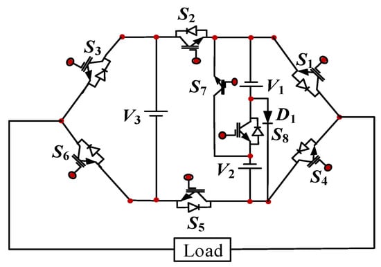
Figure 2.
Proposed hexagonal-shaped fifteen-level inverter.
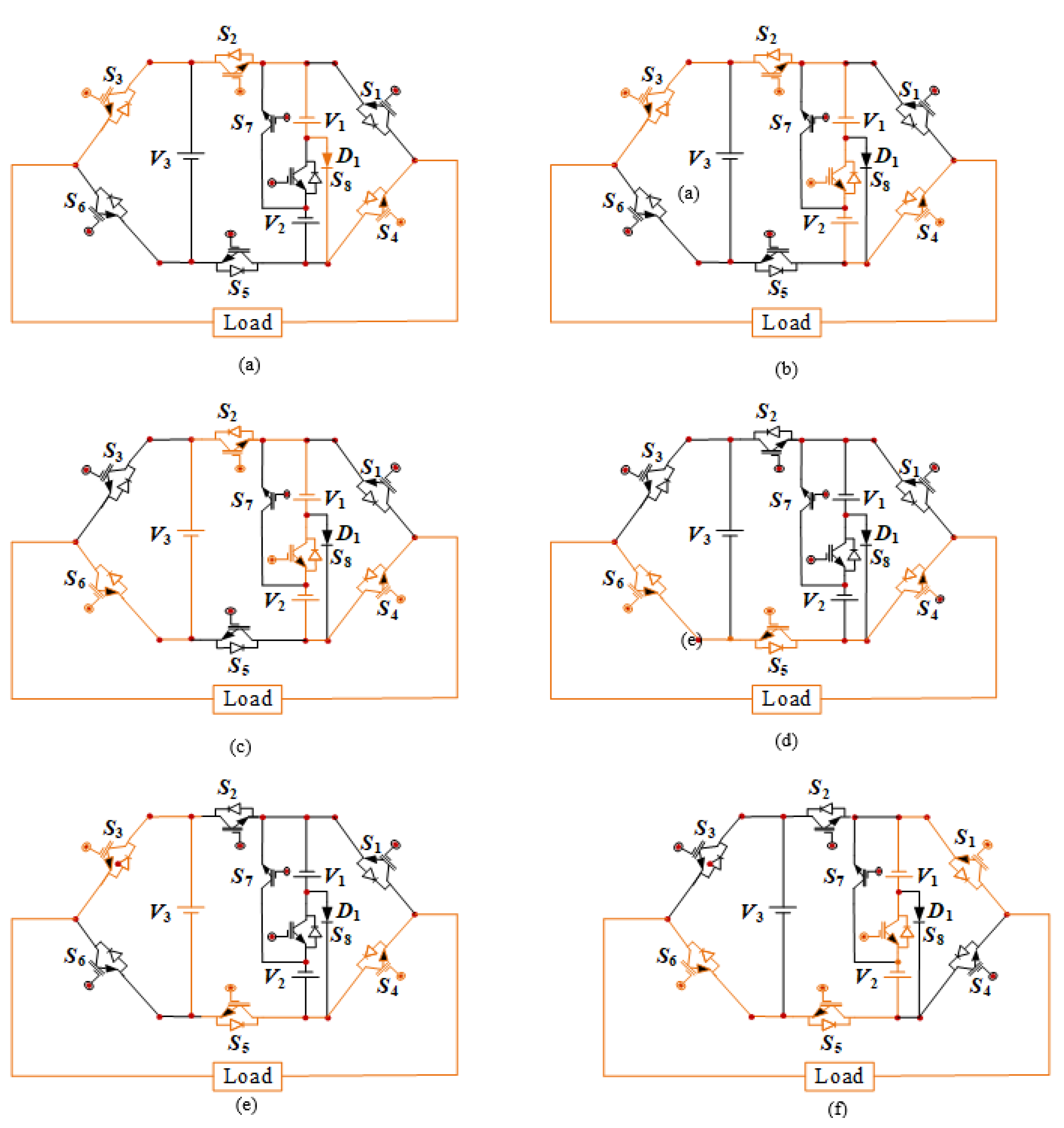
2.1. Operating Principle
In this subsection, the operating principle of the proposed topology is illustrated. The proposed topology has fifteen modes: a single zero mode, seven positive modes, and seven negative modes. To generate these fifteen modes, the proposed topology uses only eight switching devices along with three voltage sources. The values of the voltage sources are selected so that the value of V2 must be twice the times of V1, and the value of V3 will be four times that of the supply voltage V1. The switches (S1, S2) and (S3, S6) are turned on simultaneously to avoid the short circuit of dc sources. The operation of this proposed topology is illustrated in Table 2. Some voltage generation procedures are illustrated in Figure 3.
Table 2.
Operating principle of the proposed topology.
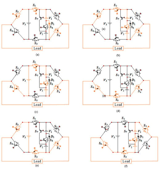
Figure 3.
Level generation procedures of output voltage: (a) V1; (b) V1 + V2; (c) V1 + V2 + V3; (d) zero; (e) −V3; (f) –(V1 + V2).
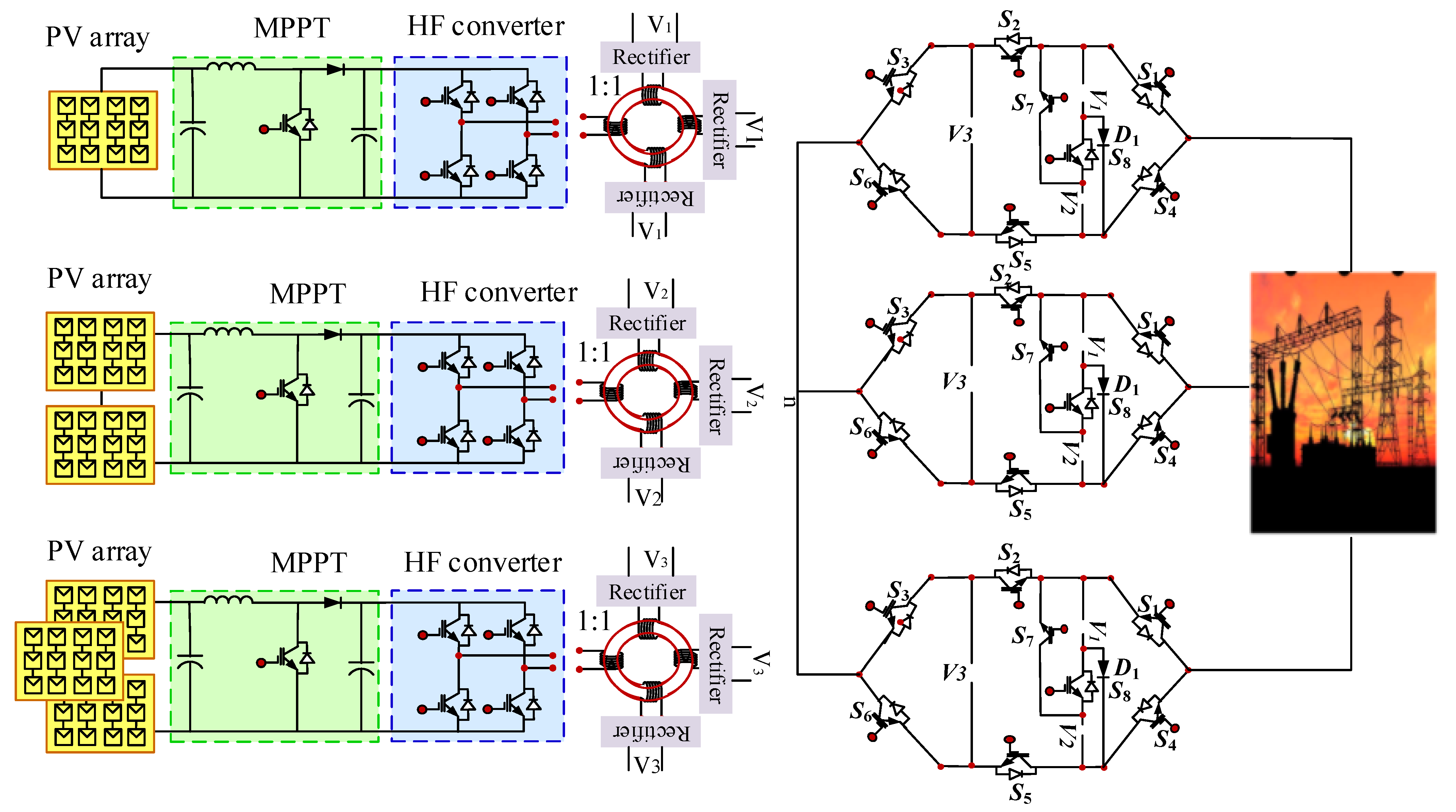
2.2. Grid Integration of Proposed Topology
This subsection deals with the detailed circuit diagram of grid integration of the proposed multilevel inverter shown in Figure 4. The multiple winding magnetic link-based multilevel inverter eliminates the problems associated with the common magnetic link, such as high leakage current that reduces the efficiency of the multilevel inverter. First, the maximum power point tracking extracts the maximum power from the PV array. Second, a boost converter is used to increase the dc-link voltage, which is then converted into ac voltage by using a high-frequency H-bridge inverter. Finally, the output from the high-frequency H-bridge inverter is connected to a high-frequency multiple-winding transformer and produces several pulse voltages at secondary winding, which are applied to the inverter through the bridge rectifier circuit, as shown in Figure 4.
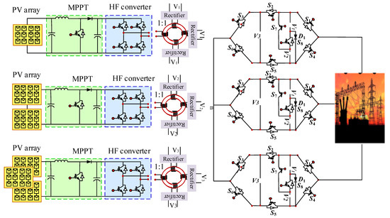
Figure 4.
Proposed hexagonal-shaped three-phase fifteen-level inverter.
2.3. Calculation of Blocking Voltage
The calculation of blocking voltages on the switching devices plays an essential role in designing multilevel inverters. Because of this, the issues around blocking voltage greatly influence the cost and size of multilevel inverters. The blocking appears across a switch when it is reverse biased, and the total blocking voltage is the sum of the individual blocking voltages required for each switch of a topology. The equation of total blocking voltage for the proposed topology can be obtained as follows:
From Equation (1), the calculated total blocking voltage is 28 × V, where V is the minimum dc-link voltage.
3. Low-Frequency Modulation Technique
Generally, low-frequency and high-frequency modulation techniques are used for generating the firing pulses of the modular multilevel inverter. However, the high-frequency modulation technique generates high total harmonic distortions resulting in high switching losses that reduce the efficiency of the modular multilevel inverter. Thus, a lower frequency modulation technique would be the optimal choice for generating fewer switching losses and lower total harmonic distortion [17]. Newton–Raphson is a very low-frequency modulation technique used to generate the firing pulse of proposed fifteen-level inverters. The Fourier series expansion of the output of the multilevel inverter is given by:
where s = (n − 1)/2, n is the level of the multilevel inverter, and k is the order of harmonic components. For the calculation of fundamental output voltage, the firing angles must be calculated, and for the calculation of the firing angle, the Newton–Raphson method is used. From Equation (2), the fundamental peak of output voltage in terms of switching angles can be written as shown in Equation (3).
From Equation (1), the expressions for fundamental voltage in terms of m, and lower order harmonic components, when they are eliminated, can be written for 15-level proposed topology as:
This topology, however, still produces high total harmonics distortion. For this reason, the low-frequency half-height method, which produces not only low total harmonic distortion but also generates high inverter losses, is used in this paper [18]. The switching angle is calculated using this method by:
Here, j = 1, 2, ………,. K is the number of levels of output voltage. With Equation (5), the calculated switching angles for the proposed fifteen-level inverter are tabulated in Table 3.
Table 3.
Main switching angle for the proposed fifteen-level inverter.
4. Simulation Results
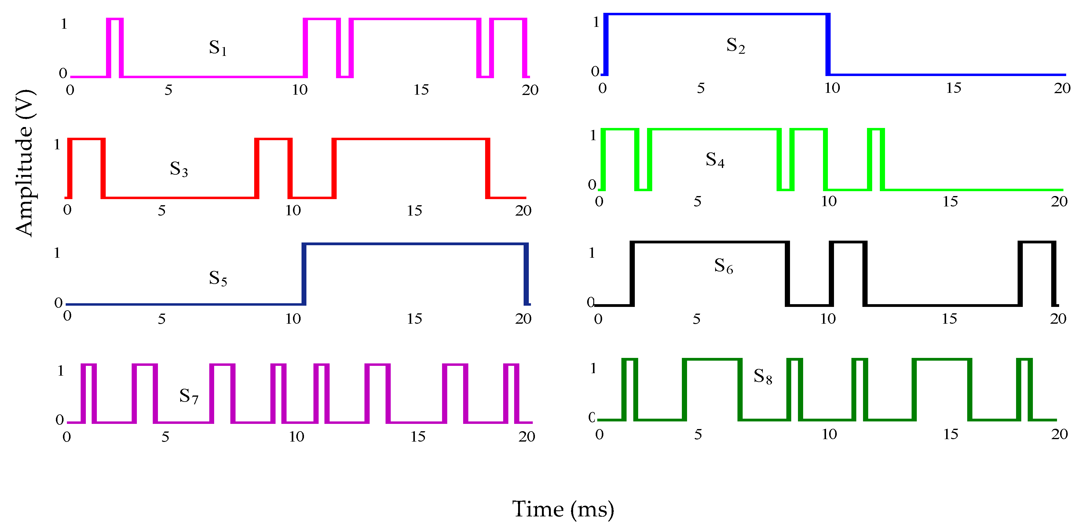
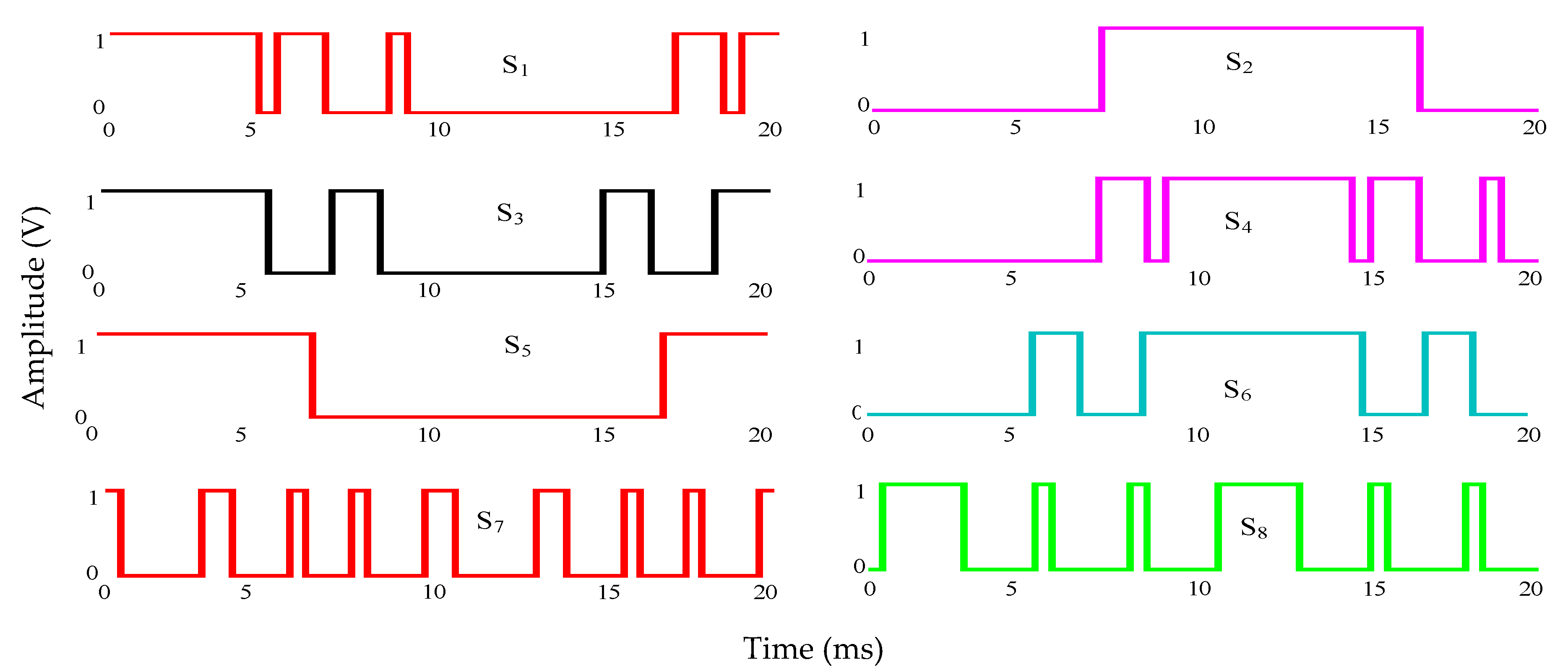
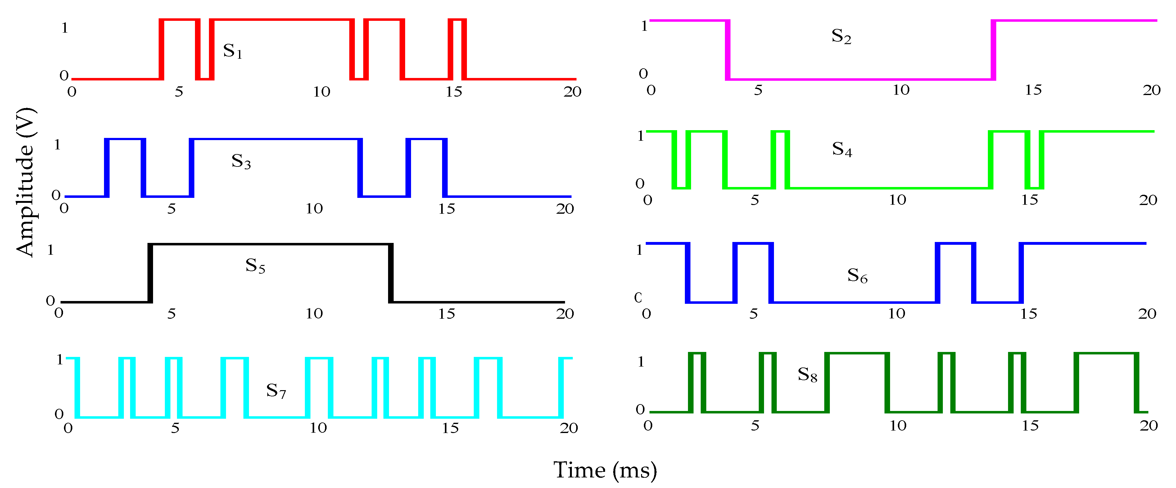
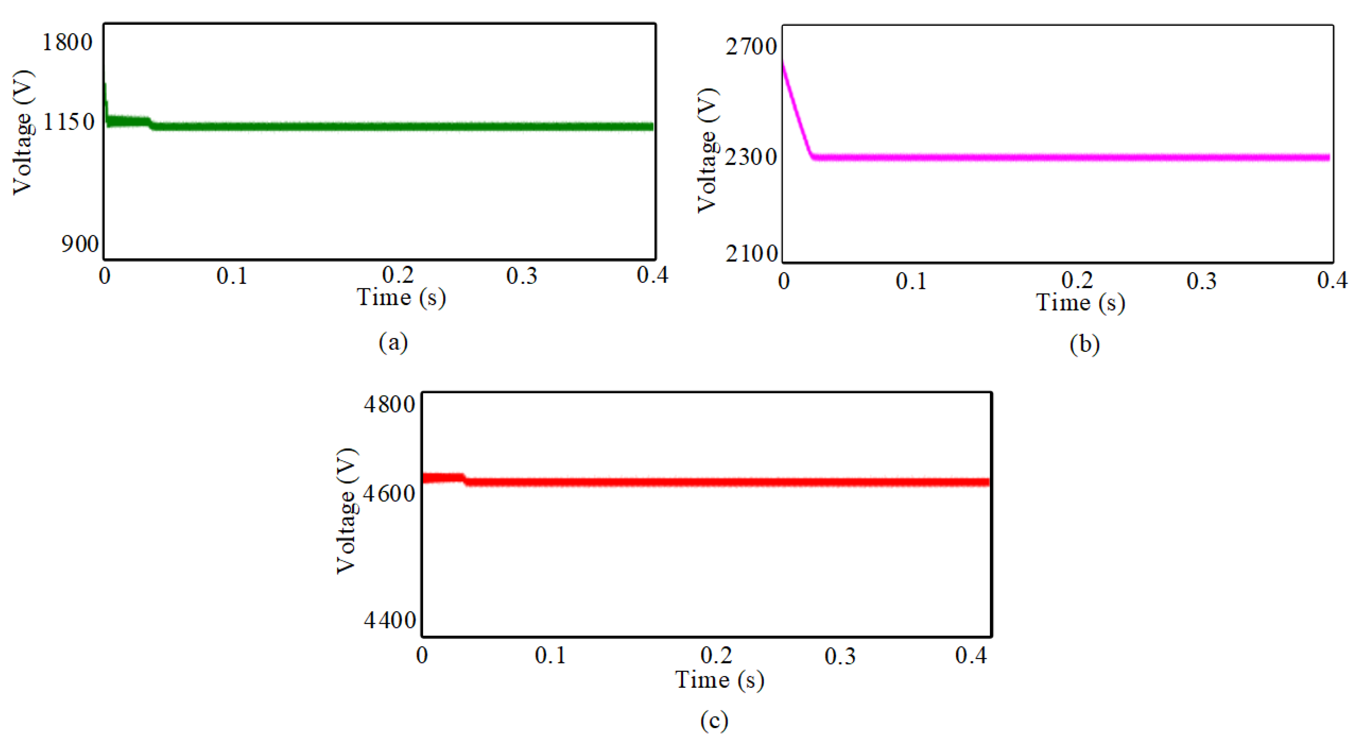
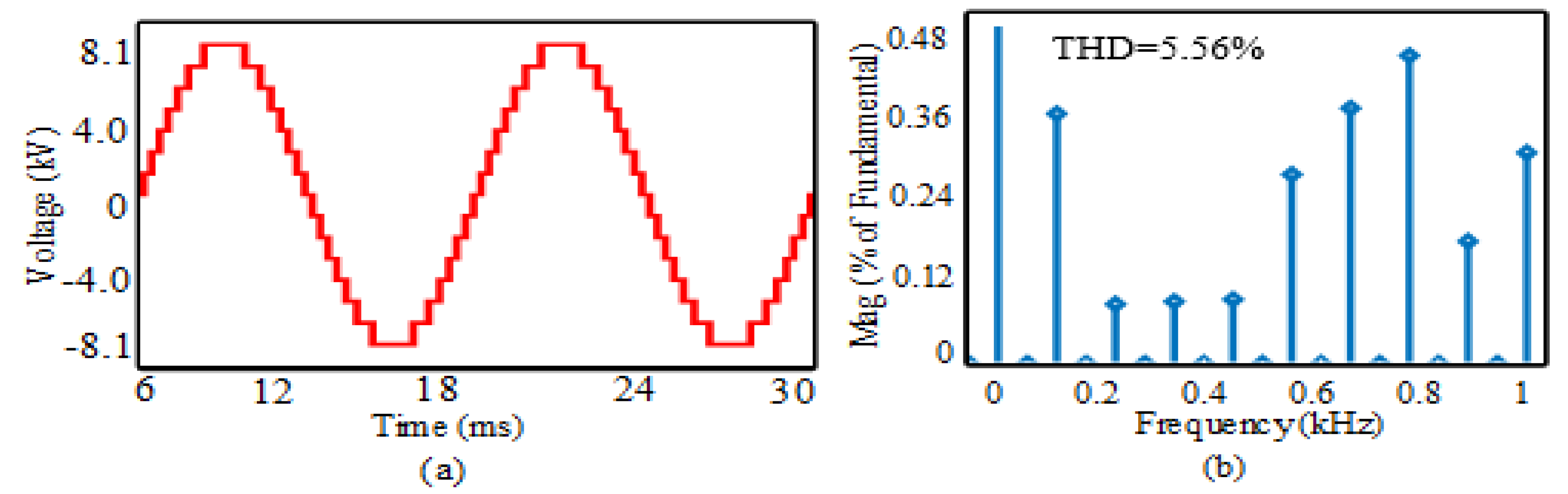
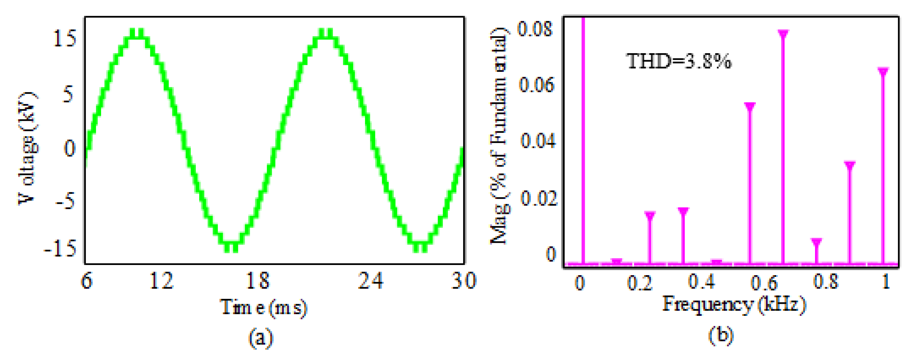
The total simulation has been performed in the MATLAB Simulink environment. Here, for the generation of firing pulses of the proposed inverter, a low-frequency modulation scheme is used and was generated by the low-frequency half-height algorithm. The switching patterns of the proposed topology for phase A, phase B and phase C are shown in Figure 5, Figure 6 and Figure 7, respectively. The simulation parameters are illustrated in Table 4. The output of three high-frequency rectifiers is depicted in Figure 8. The phase voltage, and the frequency spectrum of the proposed topology, are shown in Figure 9a,b. It is seen from Figure 9a that the proposed topology has fifteen levels in output voltage, and in Figure 9b that it generates only 5.56% of the THD. Figure 10a,b show the output line voltage and its harmonics spectrum. The output line voltage produces only 3.8% of the THD, displayed in Figure 10b. The line voltage and its harmonic spectrum at the load terminal are illustrated in Figure 11a,b. The results show that only 0.25% of the THD is found.
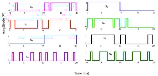
Figure 5.
Switching pattern of the proposed hexagonal-shaped three-phase fifteen-level inverter for phase-A using the half-height method.
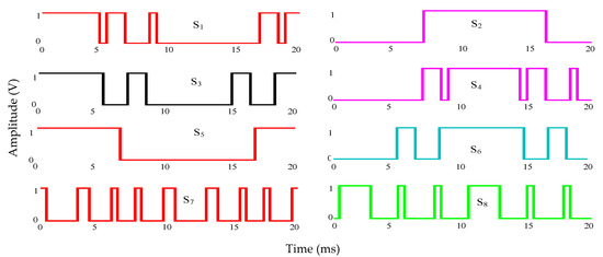
Figure 6.
Switching pattern of the proposed hexagonal-shaped three-phase fifteen-level inverter for phase-B using the half-height method.
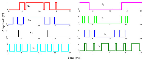
Figure 7.
Switching pattern of the proposed hexagonal-shaped three-phase fifteen-level inverter for phase-C using the half-height method.
Table 4.
Simulation parameters.
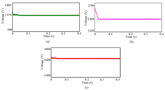
Figure 8.
Outputs of three high-frequency rectifiers of the proposed hexagonal-shaped three-phase-fifteen level inverter: (a) V1; (b) V2; and (c) V3.
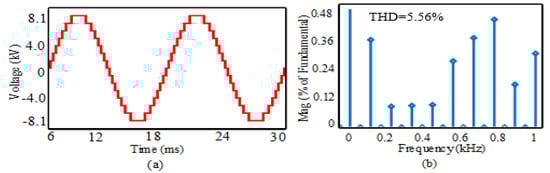
Figure 9.
The proposed hexagonal-shaped three-phase fifteen-level inverter (a) phase voltage and (b) frequency spectrum.
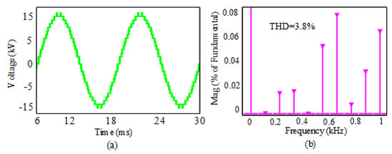
Figure 10.
The proposed hexagonal-shaped three-phase fifteen-level inverter (a) line voltage and (b) frequency spectrum.
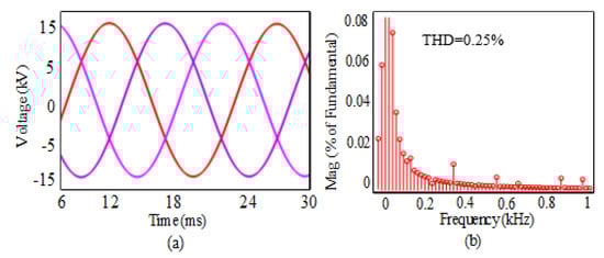
Figure 11.
Response of proposed hexagonal-shaped three-phase fifteen-level inverter (a), line voltage, and (b) frequency spectrum (at load terminal).
5. Comparative Analysis
This section deals with the comparative analysis of the proposed hexagonal-shaped three-phase fifteen-level inverter with recently published topologies. Here, the comparison parameters are presented based on the number of components, total blocking voltage, the overall cost, weight, and size of the device, the total rating, and the maximum number of active switches per level. Based on these factors, it has been decided which topology is more suitable for specific applications.
5.1. Number of Components
The total number of components bears a direct correlation to the cost, size, and weight of the inverter. With that in mind, a comparison is made among the proposed topology and other recently published topologies based on a total number of components and is shown here in Table 5. It is evident from Table 5 that the proposed topology has utilized the minimum number of IGBT‘s and power diodes in producing single-phase fifteen-level output voltage. Component reduction considering conventional cascaded H-bridge fifteen level inverter (CHB) is around 65.7%, which is higher than other mentioned topologies and suggests its superiority in that respect.
Table 5.
Components comparison of different asymmetric fifteen-level inverter.
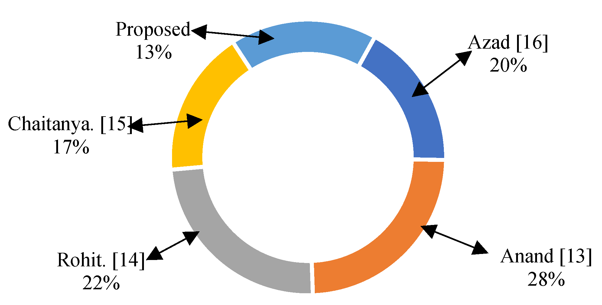
5.2. Total Blocking Voltage (TBV)
Another parameter in the comparison relates to the issue of total blocking voltages. Blocking voltage relates directly to the cost and size of the switches, and the minimum total blocking voltage ensures the lowest cost and size of a switch. Therefore, for designing an optimal multilevel inverter, the lowest blocking voltage must be ensured. The pie-chart shown in Figure 12 presents the amount of used total blocking voltage of different asymmetric multilevel inverters. Overall, variation of used total blocking voltage among different topologies is quite noticeable. Figure 12 shows that the proposed topology offers lower blocking voltages than other mentioned topologies. Therefore, it can be concluded that the proposed topology performs better in terms of total blocking voltages.
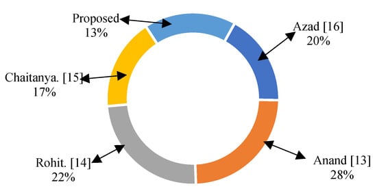
Figure 12.
Comparison of proposed topology with existing asymmetric topologies in terms of total blocking voltage.
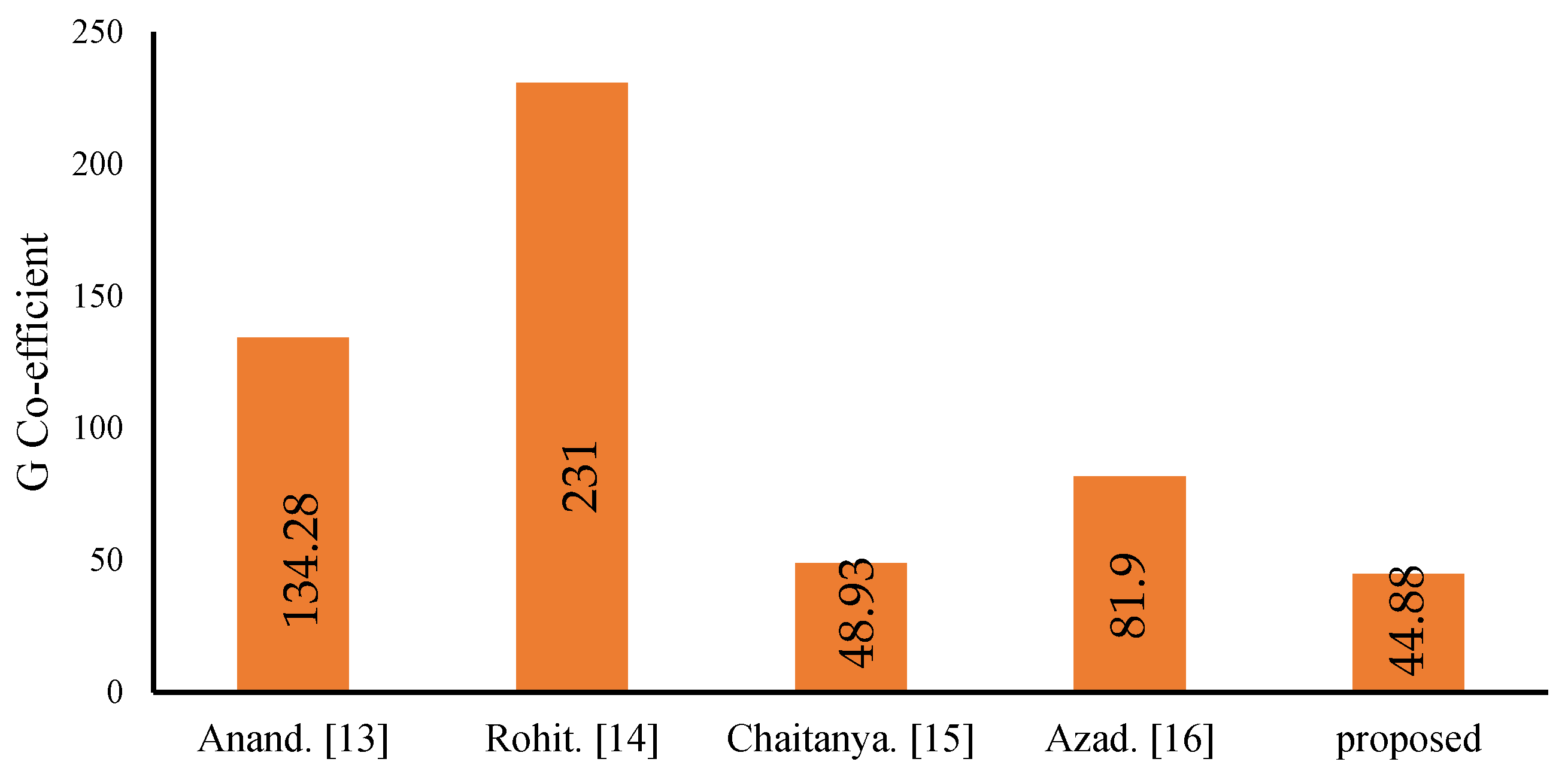
5.3. Overall Cost, Weight, and Size
Another point of comparison between the proposed topology and the others is the estimate of the cost, weight, and size of the device. The cost, weight, and size of the multilevel inverter relate directly to the quantity of its segments, for example, switching devices, dc voltage sources, and the voltage rating of IGBTs. With this in mind, and to compare the proposed topology to different topologies, from the perspective of the cost and size, the G coefficient is defined as follows [19]:
The calculated G-coefficient is presented in Figure 13. From this figure, it can be seen that the value of coefficient G is lower in the proposed typology than the other mentioned in this article. Therefore, it can be speculated that the proposed topology offers low weight and small size with the lowest cost.
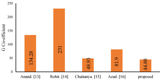
Figure 13.
Comparison of G coefficient.
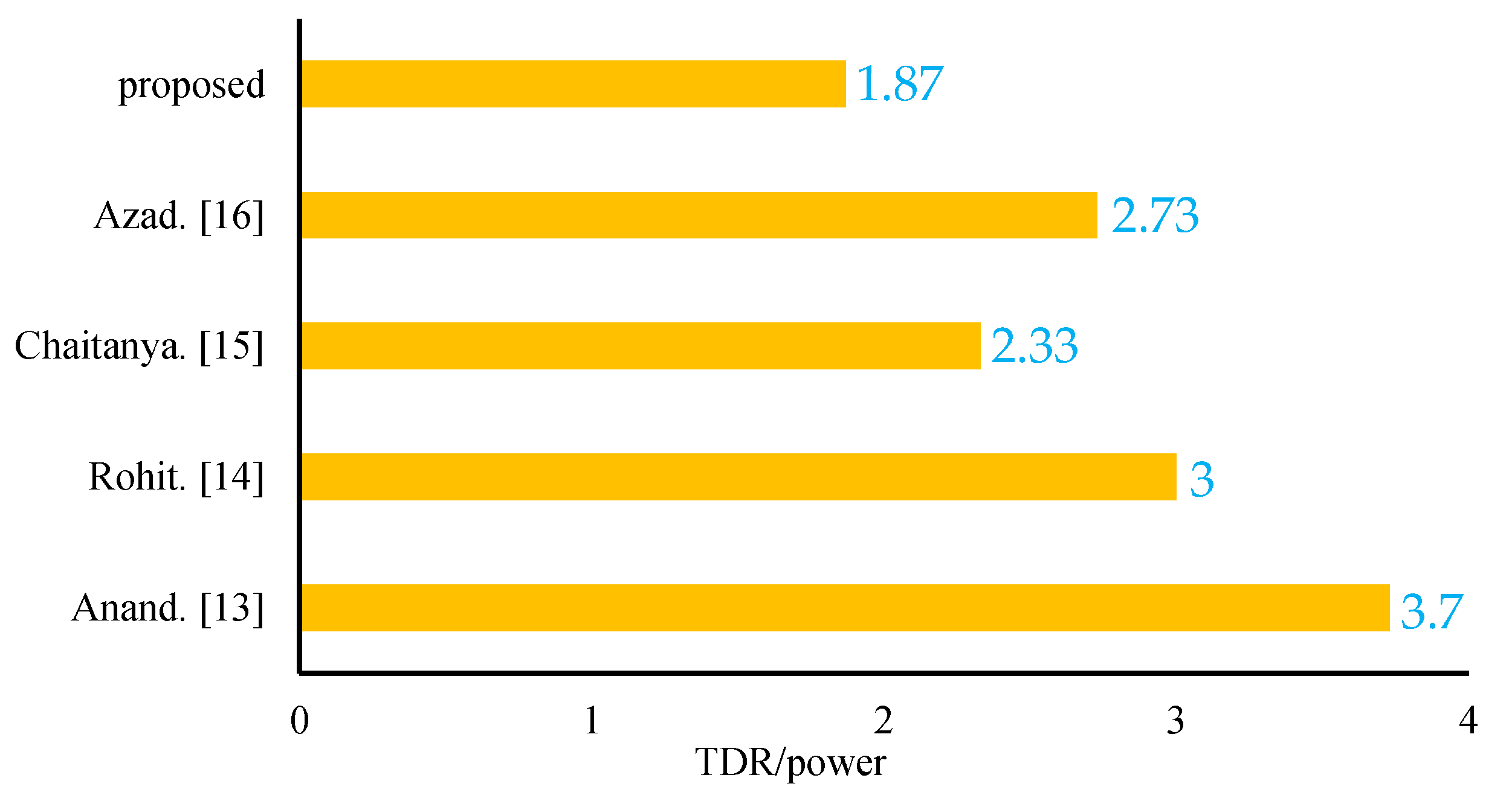
5.4. Total Device Rating (TDR)
The last element of the comparison in this study is the total device rating. Each switch of the proposed topology carries a load current. Thus, the current stress is equivalent to the load current. Again, their voltage stress will be equal to the blocking voltage. Therefore, total device rating (TDR) can be calculated as follows [19]:
where is the device rating of the switch (si). For designing a multilevel inverter topology, it is imperative that the total device rating of a multilevel inverter is at a minimum. This low value will ensure that the requirements for the cost, weight and size of the designed topology stay minimal. A comparison with other topologies was carried out based on the value of TDR per power and is presented in Figure 14. It is clear from Figure 14 that the proposed topology utilizes the minimum value of TDR/power, a ratio lower than that of the other topologies mentioned in this paper. Therefore, it can be summarized that the size, weight, and cost of the proposed topology will be reduced from the point of view of TDR/power.
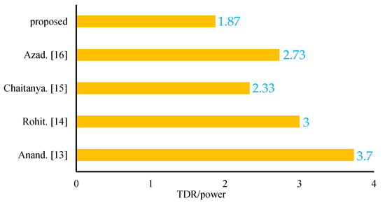
Figure 14.
Comparison based on TDR per power.
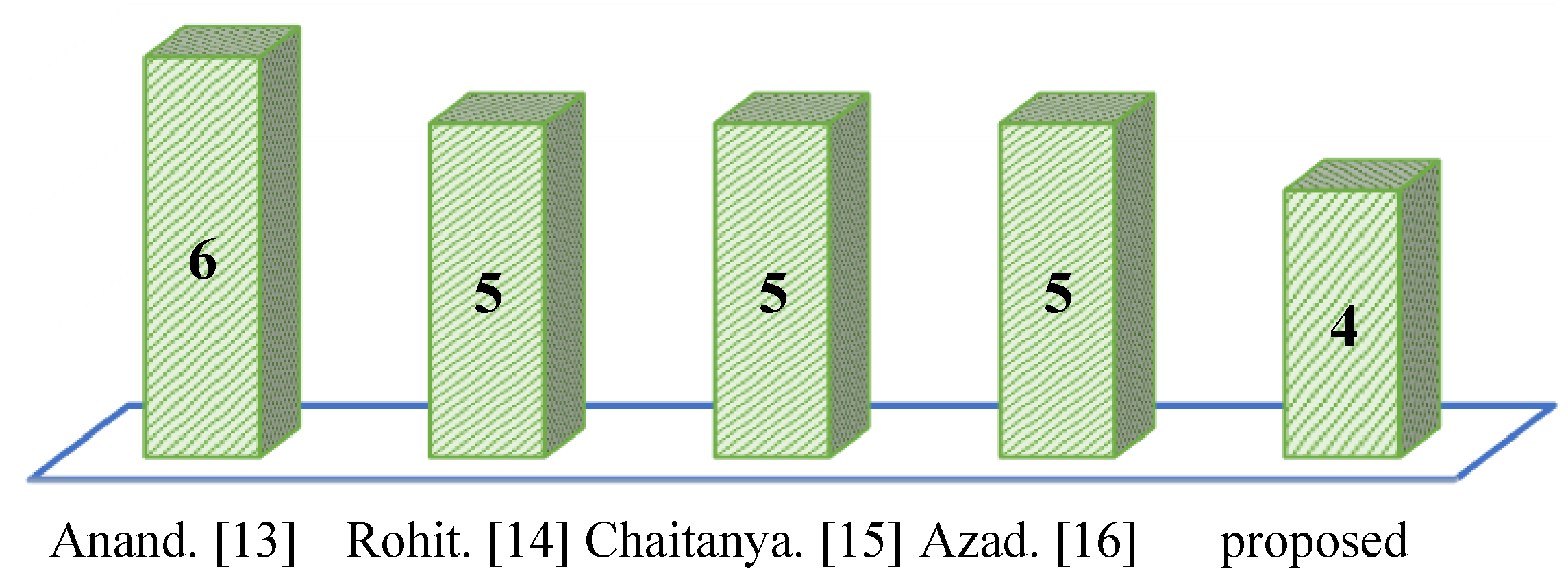
5.5. Maximum Number of Active Switches Per Level
This subsection examines recently published topology performance relating to the maximum number of active switching devices. The highest number of active switching devices leads to the large size of semiconductor devices and increased size and cost of the inverter. Thus, in designing an inverter, the number of active switching devices must be calculated to ensure the proposed inverter uses the lowest active switching device. A comparison with different topologies discussed in this study was conducted based on the maximum number of active switches per level and is presented in Figure 15. The bar diagram in Figure 15 indicates that the newly proposed topology utilized the minimum number of active switches.
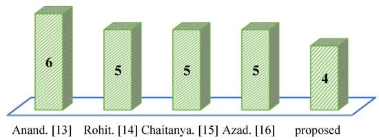
Figure 15.
Comparison of different topologies based on a maximum number of active switches per level.
6. Compliance with Grid Code
With the increased penetration level of PV power plants and distributed generators, compliance with grid codes has attracted much attention. Complying with the grid code rules while keeping the cost and the number of devices low is now a popular topic of research. The harmonics in the power systems can be considered as a power quality problem usually produced by the inverters and converters of renewable energies and loads. The harmonics lead to the following effects on the power systems [20]:
- i.
- Reduction in the functionality of power system protection devices
- ii.
- Additional losses in the power grids
- iii.
- Reduction of the lifetime of some types of loads feeding on the grid.
The total harmonic distortion in voltage or the current is considered a remarkable indicator for the harmonics in the power system. The acceptable THD differs from one voltage level to another and from one country to another. Table 6 illustrates the acceptable limits of THD for each voltage level in different countries [20,21,22,23,24,25].
Table 6.
Acceptable THD in different countries and standards.
The proposed inverter, unlike many others, can work without filters in two levels of voltage, which leads to the reduction in the total cost of the PV grid-tied system of up to more than USD 7000. Table 7 shows the need for filters in the grid-tied PV systems according to the voltage level in different countries. The study shows that according to most of the grid codes integrating PV systems to the grid in low voltage, below 1 kV does not require filters for the proposed inverter, which is widely used in roof-top and houses. For the voltage level between 1 kV and 69 kV, in most countries and according to IEEE 519 and IEC6100-3-2 standards, no filters are required for the proposed inverter except for the UK power grid. For voltage levels higher than 69 kV, a filter is required to achieve the grid code requirements according to all countries’ grid codes and different standards. This illustrates that, generally, the proposed inverter will achieve the grid code requirements in small-scale and medium-scale grid-tied PV systems without the need for filters. The proposed inverter is the most applicable one in many applications, including floating PV [26].
Table 7.
Need for filters for the proposed inverter according to the grid code requirements.
7. Conclusions
This paper introduced a new hexagonal-shaped fifteen-level inverter for the grid-integrated solar photovoltaic system as an alternative to the conventional multilevel inverters. The proposed topology reduced the number of components to around 58%, compared to the state-of-the-art topologies. In addition, it curtails almost 57% of the TBV level and TDR/power than the state-of-the-art topologies. Moreover, it ensures the lowest cost for implementation on hardware. The low-frequency modulation technique, which generates the switching pulses for controlling the proposed inverter topology, provides the lowest total harmonics distortion. The results show that, at small and medium scales PV systems, the proposed inverter does not require a filter to achieve the grid code requirements for PV integration. Thus, the proposed inverter topology makes the solar photovoltaic systems more compact, efficient, and reliable in the future power world.
Author Contributions
Conceptualization, M.T.I.; methodology, M.T.I., H.H.F.; software, M.T.I.; validation, H.H.F.; formal analysis, H.H.F.; investigation, H.H.F.; resources, E.R.; data curation, M.T.I. and H.H.F.; writing—original draft preparation, M.T.I. and H.H.F.; writing—review and editing, H.H.F., E.R. and M.F.R.; visualization, E.R. and M.F.R.; supervision, E.R. and M.F.R.; project administration, H.H.F. and M.F.R.; funding acquisition, E.R. All authors have read and agreed to the published version of the manuscript.
Funding
This work was carried out within the framework of the research project DREAM (Dynamics of the REsources and technological Advance in harvesting Marine renewable energy), supported by the Romanian Executive Agency for Higher Education, Research, Development and Innovation Funding – UEFISCDI, grant number PN-III-P4-ID-PCE-2020-0008.
Institutional Review Board Statement
Not applicable.
Informed Consent Statement
Not applicable.
Data Availability Statement
No data except that mentioned in the paper.
Conflicts of Interest
The authors declare no conflict of interest.
References
- Roy, T.K.; Mahmud, A.; Oo, A.M.T.; Bansal, R.; Haque, E. Nonlinear Adaptive Backstepping Controller Design for Three-Phase Grid-Connected Solar Photovoltaic Systems. Electr. Power Compon. Syst. 2017, 45, 2275–2292. [Google Scholar] [CrossRef]
- Fayek, H.; Kotsampopoulos, P. Central Tunicate Swarm NFOPID-Based Load Frequency Control of the Egyptian Power System Considering New Uncontrolled Wind and Photovoltaic Farms. Energies 2021, 14, 3604. [Google Scholar] [CrossRef]
- Fayek, H.H. 5G Poor and Rich Novel Control Scheme Based Load Frequency Regulation of a Two-Area System with 100% Renewables in Africa. Fractal Fract. 2020, 5, 2. [Google Scholar] [CrossRef]
- Islam, T.; Rahman, F.; Maruf, H.; Roshid, H.U. Novel Multicarrier Arrangement for Generating Switching Pulses of Symmetric and Asymmetric Multilevel Inverters with lowest THDS. In Proceedings of the 2021 International Conference on Automation, Control and Mechatronics for Industry 4.0 (ACMI), Rajshahi, Bangladesh, 8–9 July 2021; pp. 1–6. [Google Scholar]
- Islam, R.; Mahfuz-Ur-Rahman, A.M.; Muttaqi, K.M.; Sutanto, D. State-of-the-Art of the Medium-Voltage Power Converter Technologies for Grid Integration of Solar Photovoltaic Power Plants. IEEE Trans. Energy Convers. 2019, 34, 372–384. [Google Scholar] [CrossRef]
- Rodriguez, J.; Franquelo, L.G.; Kouro, S.; Leon, J.I.; Portillo, R.; Prats, M.A.M.; Perez, M.A. Multilevel Converters: An Enabling Technology for High-Power Applications. Proc. IEEE 2009, 97, 1786–1817. [Google Scholar] [CrossRef] [Green Version]
- Farhadi-Kangarlu, M.; Babaei, E. A Generalized Cascaded Multilevel Inverter Using Series Connection of Submultilevel Inverters. IEEE Trans. Power Electron. 2013, 28, 625–636. [Google Scholar] [CrossRef]
- Islam, R.; Guo, Y.; Zhu, J. A Multilevel Medium-Voltage Inverter for Step-Up-Transformer-Less Grid Connection of Photovoltaic Power Plants. IEEE J. Photovoltaics 2014, 4, 881–889. [Google Scholar] [CrossRef]
- Islam, R.; Mahfuz-Ur-Rahman, A.M.; Islam, M.; Guo, Y.G.; Zhu, J.G. Modular Medium-Voltage Grid-Connected Converter With Improved Switching Techniques for Solar Photovoltaic Systems. IEEE Trans. Ind. Electron. 2017, 64, 8887–8896. [Google Scholar] [CrossRef] [Green Version]
- Dhanamjayulu, C.; Meikandasivam, S. Implementation and Comparison of Symmetric and Asymmetric Multilevel Inverters for Dynamic Loads. IEEE Access 2017, 6, 738–746. [Google Scholar] [CrossRef]
- Prabaharan, N.; Palanisamy, K. A new hybrid asymmetric multilevel inverter with reduced number of switches. In Proceedings of the 2016 IEEE International Conference on Power Electronics, Drives and Energy Systems (PEDES), Trivandrum, India, 14–17 December 2016; pp. 1–4. [Google Scholar]
- Kanaujia, A.K.; Kumar, S. A Reduced Switch Count Hybrid Fifteen-level Inverter for an Open-End Winding Induction Motor (OEWIM) Drive. In Proceedings of the 2018 8th IEEE India International Conference on Power Electronics (IICPE), Jaipur, India, 13–15 December 2018; pp. 1–6. [Google Scholar]
- Anand, R.; Kamatchi, M. A Fifteen Level Cascaded H-Bridge Multilevel Inverter with Space Vector PWM Technique with Reduced Number of Switches. Int. J. Inf. Technol. (IJIT) 2016, 2, 17–25. [Google Scholar]
- Kumar, R.; Shimi, S.; Kaura, S. A Novel Topology of Fifteen Level Multilevel Inverter with Harmonic Elimination Using GASHE. In Proceedings of the 2018 International Conference on Power Energy, Environment and Intelligent Control (PEEIC), Noida, Greater Noida, India, 13–14 April 2018; pp. 22–28. [Google Scholar]
- Chaitanya, S.; Patnaik, N.R.; Raju, C.B. A Novel Transformerless Asymmetrical Fifteen Level Inverter Topology for Re-newable Energy Applications. In Proceedings of the 2018 Fourth International Conference on Advances in Electrical, Electronics, Information, Communication and Bio-Informatics (AEEICB), Chennai, India, 27–28 February 2018; pp. 1–4. [Google Scholar]
- Azad, A.; Kumar, J. THD Minimisation in 15- Level Hybrid Multilevel Inverter using Harmonic Minimization Technique. In Proceedings of the 2018 2nd IEEE International Conference on Power Electronics, Intelligent Control and Energy Systems (ICPEICES), New Delhi, India, 22–24 October 2018; pp. 398–402. [Google Scholar]
- Kumar, A.R.; Bhaskar, M.S.; Subramaniam, U.; Almakhles, D.; Padmanaban, S.; Nielsen, J.B.-H. An Improved Harmonics Mitigation Scheme for a Modular Multilevel Converter. IEEE Access 2019, 7, 147244–147255. [Google Scholar] [CrossRef]
- Jalakanuru, N.; Kiber, M. Switching Angle Calculation by EP, HEP, HH and FF Methods For Modified 11-Level Cas-cade H-Bridge Multilevel Inverter. Int. J. Eng. Sci. Invent. (IJESI) 2017, 6, 69–75. [Google Scholar]
- Taheri, A.; Rasulkhani, A.; Ren, H.-P. An Asymmetric Switched Capacitor Multilevel Inverter With Component Reduction. IEEE Access 2019, 7, 127166–127176. [Google Scholar] [CrossRef]
- Al-Shetwi, A.Q.; Hannan, M.A.; Jern, K.P.; Alkahtani, A.A.; Abas, A.E.P. Power Quality Assessment of Grid-Connected PV System in Compliance with the Recent Integration Requirements. Electronics 2020, 9, 366. [Google Scholar] [CrossRef] [Green Version]
- Memon, M.A.; Mekhilef, S.; Mubin, M.; Aamir, M. Selective harmonic elimination in inverters using bio-inspired intelligent al-gorithms for renewable energy conversion applications: A review. Renew. Sustain. Energy Rev. 2018, 82, 2235–2253. [Google Scholar] [CrossRef]
- IEEE Std. IEEE Recommended Practice for Utility Interface of Photovoltaic (PV) Systems; IEEE, Ed.; IEEE Standard: Piscataway, NJ, USA, 2003; pp. 929–2000. [Google Scholar]
- Schwartfeger, L.; Santos-Martin, D.; Wood, A.R.; Watson, N. Review of distributed generation interconnection standards. In Proceedings of the 2014 Electricity Engineers’ Association Conference, Auckland, New Zealand, 18–20 June 2014. [Google Scholar]
- Abdalla, O.H.; Mostafa, A.A. Technical Requirements for Connecting Solar Power Plants to Electricity Networks. In Innovation in Energy Systems—New Technologies for Changing Paradigms; Ustun, T.S., Ed.; IntechOpen: London, UK, 2019; Chapter 2. [Google Scholar]
- Abdalla, O.H.; Fayek, H.H.; Ghany, A.M.A. Secondary Voltage Control Application in a Smart Grid with 100% Renewables. Inventions 2020, 5, 37. [Google Scholar] [CrossRef]
- Ravichandran, N.; Fayek, H.; Rusu, E. Emerging Floating Photovoltaic System—Case Studies High Dam and Aswan Reservoir in Egypt. Processes 2021, 9, 1005. [Google Scholar] [CrossRef]


Publisher’s Note: MDPI stays neutral with regard to jurisdictional claims in published maps and institutional affiliations. |
© 2021 by the authors. Licensee MDPI, Basel, Switzerland. This article is an open access article distributed under the terms and conditions of the Creative Commons Attribution (CC BY) license (https://creativecommons.org/licenses/by/4.0/).