1. Introduction
As one of the four fundamental issues of rock mechanics (i.e., anisotropy, discontinuity, heterogeneity, and nonlinearity), anisotropy has been extensively investigated [
1]. Determining the deformation and strength parameters of the anisotropic rock mass is one of the most important aspects of the rock engineering practice.
Rock anisotropy refers to the characteristic that various properties of the rock (e.g., mechanical, thermal, and hydraulic) vary with direction. The main reason for the anisotropy of rock is the existence of bedding, schism, interlayering and directional fracture systems that develop in rock. Thus, research on rock anisotropy often considers anisotropic rock as an assemblage of micro-fractured rock masses.
Analytical methods have been widely adopted to investigate the anisotropy problem and provide solutions for mechanics’ research. Regarding the deformation behavior of anisotropic rock, Amadei [
2] proposed a general solution for the deformation behavior of anisotropic rock with regularly penetrated fractures, and suggested that the geometry layout, as well as the stiffness of the joints, would dominate the anisotropy of the rock’s deformation modulus. Li [
3] proposed a calculation method for the deformation modulus of a rock mass with multiple sets of fractures under the framework of stereographic projection. There is an extensive literature relating to the anisotropy strength problem. Jaeger and Cook [
4] proposed an analytical solution to the anisotropy strength problem based on a single plane of weakness theory and the Coulomb slip criterion. Their work provided an effective tool for calculating the strength of rock with a single set of penetrated fractures. Developments to this method were suggested by Tien and Kuo [
5] and Duveau and Shao [
6].
In terms of experimental research, abundant test runs were performed by Hoek and Brown [
7] under various levels of confining stress and various loading directions for schist, slate, and sandstone, in which deformation and anisotropy strength characteristics were determined. This study deepened the understanding of the anisotropic properties of rock and provided guidance for practical engineering applications. Examples of representative engineering applications can be found in some published studies [
8,
9,
10,
11].
In this study, we focused on the practical application of numerical simulations to determine the anisotropy of schist rock. First, we report the anisotropy of schist rock in engineering applications through in situ tests and analysis. We then carried out a set of specially designed multi-angle compression tests, on which two numerical simulation methods for anisotropy were based, the finite-difference-method-based explicit approach and implicit approach. We then performed an excavation simulation for a real engineering case, the exploratory tunnel CPD-1 of a hydropower station, to assess the feasibility of the implicit approach, which was adjudged to be the more practical of the two approaches outlined.
2. Field Observations of the Anisotropy of Schist Rock
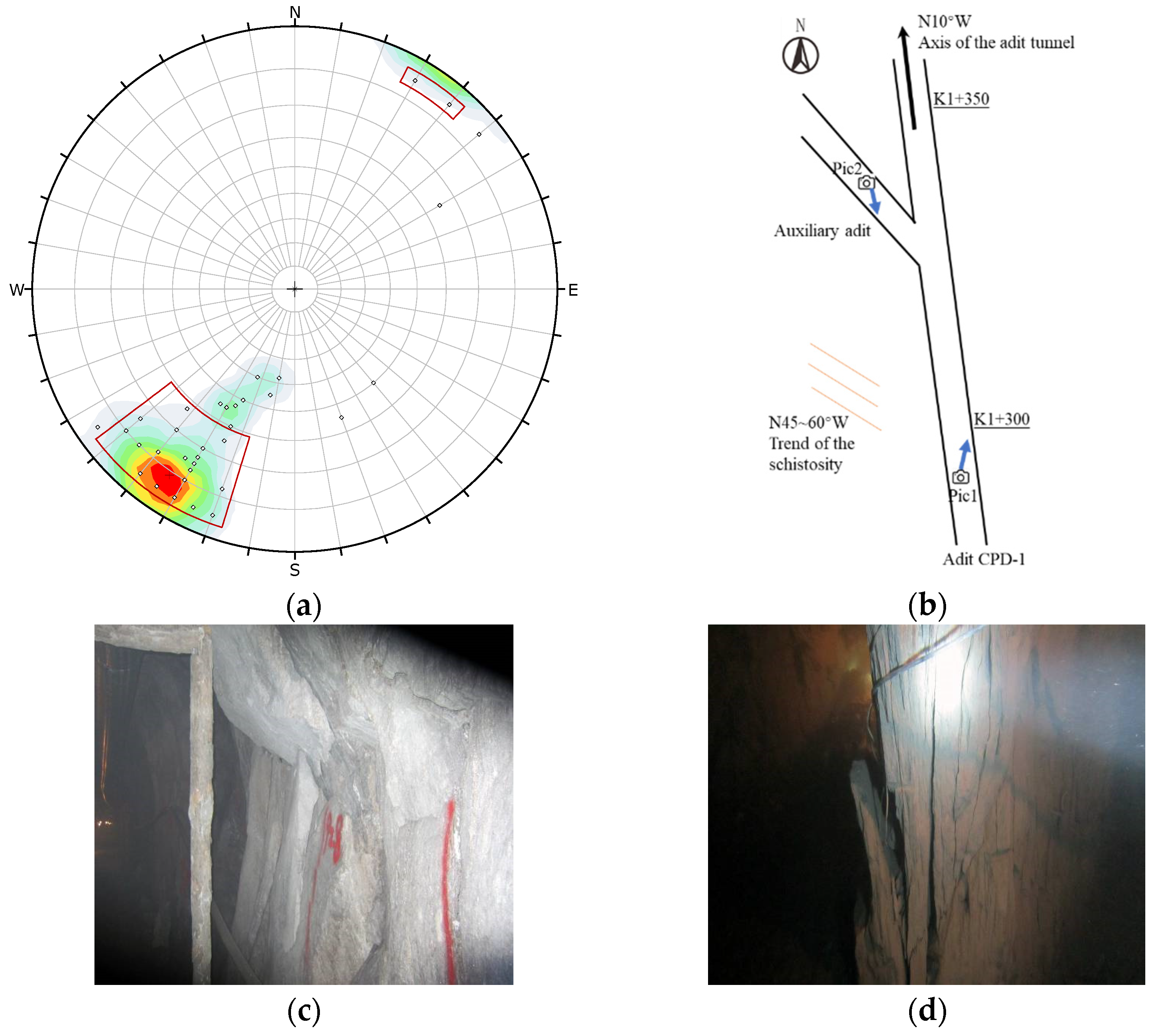
The need for the work described in this paper was highlighted by the encountered anisotropy problems of the rock mass in the Danba hydropower station located in Sichuan, China. The station is on the Dadu river and has a total capacity of 1160 MW. Its generators are supplied with water by two 17.4 km long water intake tunnels. The diameter of the two tunnels is approximately 15 m. The trend of the tunnel axis is 10–20°/NW. The buried depth of the tunnel is mostly 500–800 m, with a maximum depth of 1200 m.
From a geological perspective, the water intake tunnels are located mainly in the metamorphic rock formation of the Silurian system. The surrounding rock mass strata possess a prominent orientation of 45–85°/30–45° (dip angle/dip direction) and mainly consists of an Smx4 stratum dominated by quartz mica schist. The mechanical strength of the schist rock mass is low, meaning it can be classified as soft rock. Due to the schistosity, the strength and deformation of the surrounding rock mass exhibits significant anisotropy. These early findings show that the anisotropy of the schist rock poses a serious engineering problem. To deal with this issue, a long adit tunnel CPD-1 was excavated during the geological investigation phase, with an axis direction that coincides with the planned water intake tunnels. The cross-section of CPD-1 is a 2 × 2 m square shape.
The anisotropy of the schist rock mass immediately emerged in the excavation process and in rock mechanics tests conducted in CPD-1, which could be summarized as follows:
(1) Spalling in the surrounding rock mass
It is a well-known fact that the stability of the surrounding rock mass of a tunnel would be largely affected by the intersection angle between the dominant orientation of the rock formation and the tunnel axis direction. If a small intersection angle exists between the rock formation and the tunnel trend, the stability of the surrounding rock will be in an unfavorable state.
This phenomenon was confirmed in the adit tunnel CPD-1. The spalling of the surrounding rock at various tunnel locations was dominated by the intersection angle with the schistosity. Typical examples are presented in
Figure 1. The spalling in the auxiliary adit is more obvious than that of the main adit because the schistosity intersects the sidewall of the auxiliary adit with a small angle (≈10°), while it intersects the sidewall of the main adit with a relatively large angle (≈40°). This difference in spalling could be considered as the field expression of anisotropy of the schist rock mass.
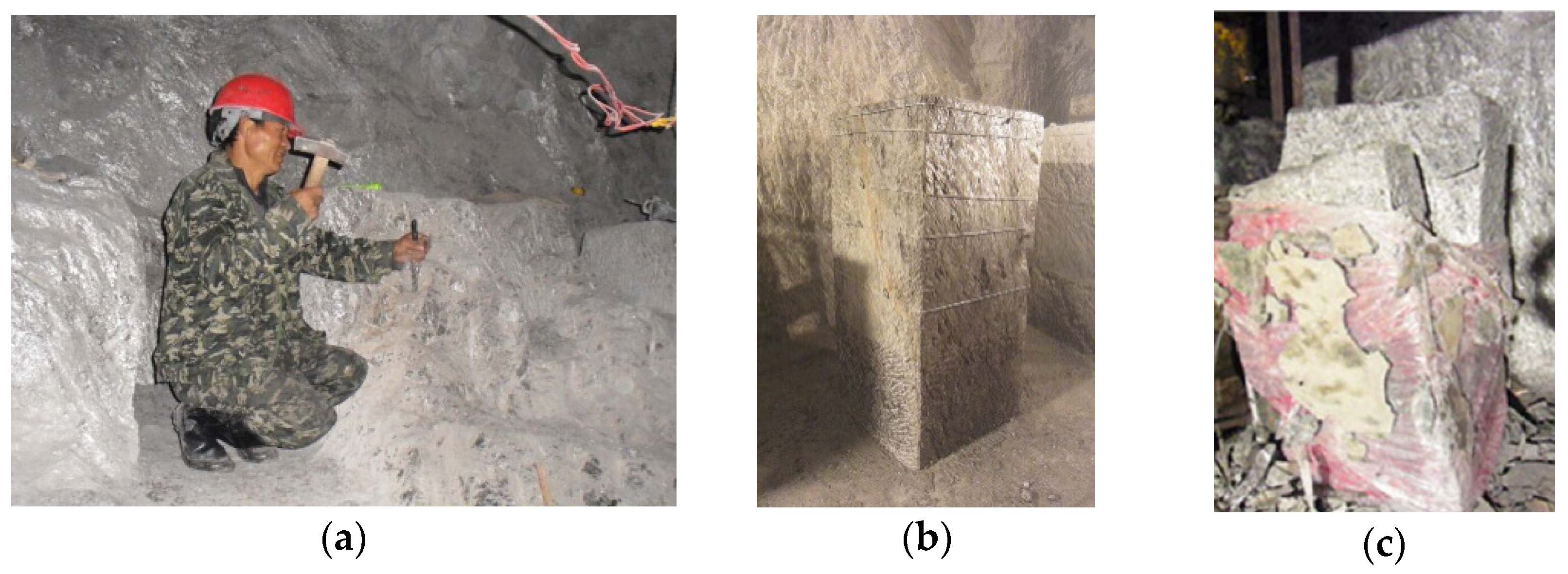
(2) In situ test conducted in CPD-1 tunnel
As a response to the field expression of anisotropy of the schist rock mass and to carry out a preliminary investigation of the anisotropic mechanical parameters, plate loading tests were conducted in the auxiliary adit where the trend of the tunnel closely coincided with that of the schist formation. The rock masses at the tunnel floor and sidewall were tested. The loading direction for floor tests was roughly parallel to the schistosity, while for the sidewall tests it was roughly perpendicular to the schistosity. The results of the tests are listed in
Table 1. Due to the strong anisotropy of the rock mass, the degree of excavation-induced disturbance was different for the floor and the sidewall, which interfered with the plated loading test data. For example, the tested modulus perpendicular to schistosity was 18 times greater than the modulus parallel to schistosity. Therefore, the plate loading test revealed the anisotropic characteristics of the schistosity rock mass, but the credibility of the results is limited. Thus, a series of sophisticated in situ triaxial tests were carried out.
The in situ true triaxial test was performed with the YXSW-12 triaxial test system [
12]. Multiple cubic specimens, with dimensions of 0.5 × 0.5 × 1.0 m, were hand-made and tested, as shown in
Figure 2. The purpose of making samples by hand was to minimize the disturbance during the unloading process. With the in situ true triaxial test, the deformation and strength parameters both perpendicular and parallel to schistosity were obtained (
Table 2). Note that the results for loose rock mass refer to the results obtained at the confinement level of 0–5 MPa, since at this low confining stress level the unloading cracks in the loose rock mass are not closed yet. The results for the intact rock mass refer to those obtained at a confinement level of 5–9 MPa, since unloading cracks are typically closed within this confinement range.
Table 2 and
Table 3 indicate that the deformation modulus when the loading direction is perpendicular to the schistosity is always smaller than when the loading direction is parallel to the schistosity, regardless of whether the rock mass was loose or intact. This indicates that the compression that occurred on the schistosity surface would decrease the stiffness of the rock and reduce the deformation modulus. We calculated the modulus anisotropic ratio
using the data in
Table 2 and obtained
, suggesting significant anisotropy exists in the Danba schist.
3. Laboratory Test of the Anisotropy of Schist Rock
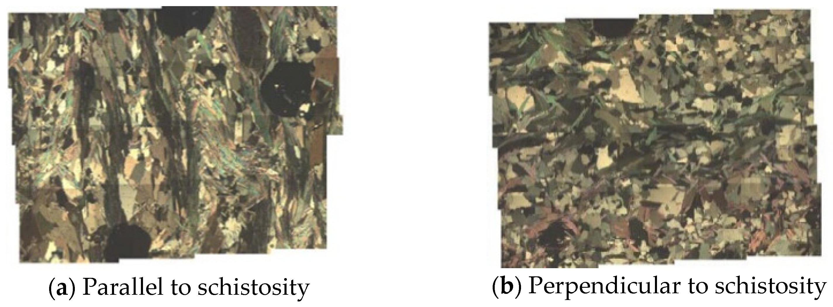
Figure 3 shows microscopic images of the Danba quartz mica schist slice under a polarizing microscope, in which different gray levels correspond to different mineral compositions. A significant proportion of white mica can be seen, which is distributed in flakes.
Figure 3 shows a directionally developed schistosity, which is the fundamental reason for the anisotropy of the quartz mica schist.
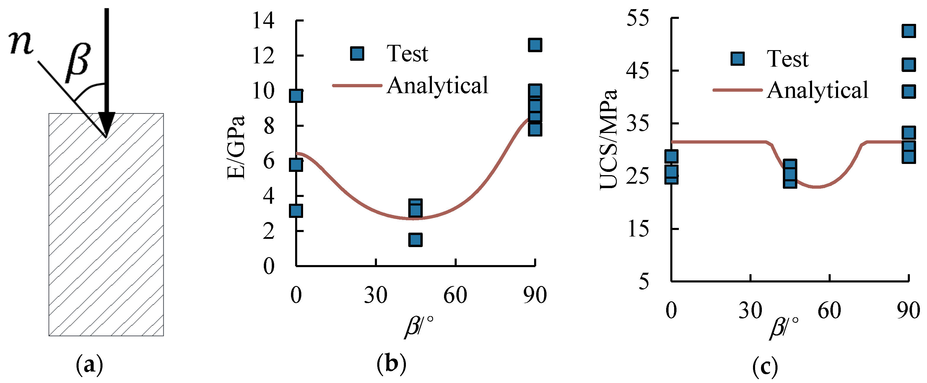
Laboratory tests were conducted to investigate the anisotropy problem for the Danba schist. A set of specially designed multi-angle uniaxial compression tests was planned. Cylindrical specimens with a diameter of 50 mm and height of 100 mm were drilled out of the cores, and the sides of the specimens were polished to a smooth texture for testing.
The convention of the loading angle
can be found in
Figure 4a. The test results (blue squares in
Figure 4b,c) show that the elastic modulus of quartz mica schist was dominated by the intersection angle of schistosity and loading direction. The mean value of the modulus at
= 0° was 6.2 GPa; at
= 45°, it was 2.7 GPa; and at
= 90°, it was 9.4 GPa. Thus, when the loading direction obliquely intersected the schistosity, the obtained modulus was lowest, and, when the loading direction is parallel to the schistosity, the modulus reached its maximum value.
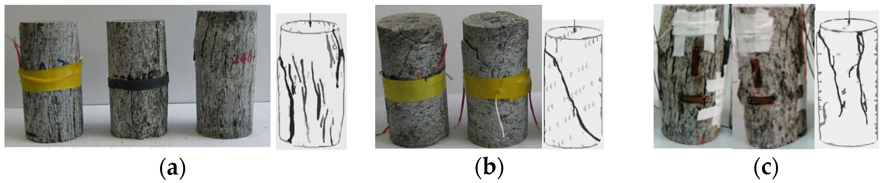
Similar to the trend of the modulus versus
, the uniaxial compressive strength (UCS) was also affected by the intersection angle of schistosity and loading direction, and it appears to be smallest when it is obliquely intersected. The failure mode is also controlled by the angle
. The failure modes of the tested specimens under different
are shown in
Figure 5.
From a microscopic perspective, the schistosity contained in the quartz mica schist is essentially metamorphic structure planes that are embedded in the rock matrix. The anisotropy behavior of the schist rock is essentially transverse isotropy brought about by the schistosity layers. A practical approach to quantitatively describe the anisotropic characteristics of quartz mica schist is to consider the equivalent mechanical behavior as the interaction of the rock matrix and schistosity layers, that is, the quartz mica schist can be regarded as a mini “layered fractured rock mass” composed of the rock matrix and schistosity. In this way, the solution of the fractured rock mass can be introduced to investigate the anisotropy behavior of the schist rock. The equivalent deformation parameters of the schist rock can be expressed as:
where
and
are the equivalent modulus and Poisson ratio of the schist rock, respectively;
and
are the modulus and Poisson ratio of the rock matrix, respectively;
,
, and
are the normal stiffness, shear stiffness, and spacing of the schistosity plane, respectively; and
is the loading angle following the convention in
Figure 4.
The equivalent deformation parameters of the schist rock can be expressed following Jaeger’s [
4] single plane of weakness theory as follows:
where
is the confining stress;
and
are the cohesion and friction angle of the fractures, respectively;
and
are the cohesion and friction angle of the rock mass, respectively;
is the maximum axial stress; and
is the loading angle following the convention in
Figure 4.
By assuming a virtual spacing of 5 mm of the schistosity plane, the parameters in Equations (1)–(5) can be calibrated based on the test data in
Figure 4, as listed in
Table 3. With these parameters, the test data in
Figure 4 were then analytically expressed as the red line in
Figure 4b,c. It can be seen that an acceptable match can be made, especially for the deformation behavior. This indicates that our assumption to consider the quartz mica schist as a “layered fractured rock mass” may be appropriate to solve the anisotropic problem of the current Danba schist.
4. Practical Numerical Simulation of the Anisotropy of Schist Rock
In the practical numerical simulation work for the layered fractured rock mass, the manifestation of layered fractures could be presented with two approaches, an explicit or an implicit approach. For the explicit approach, the layered fractures were simulated with the “joint” elements or “contact” elements, e.g., the Goodman element in the finite element method, the contact element in the discrete element method, and the “smooth joint” element in the particle flow code method. The implicit approach established the anisotropic constitutive model in the continuum medium. The implicit approach considers the rock mass as a continuum with anisotropic behaviors and simulates the anisotropy with anisotropic constitutive models.
The explicit approach directly constructs the micro-structural planes that cause the anisotropy of rock mechanical properties in the numerical model. Therefore, the explicit approach is simple and easy to understand, and no complex constitutive model is required. However, when simulating a rock mass that consists of micro-fractures with an extremely small spacing, the element size in the numerical model is controlled by the spacing, which may lead to a huge number of elements and unacceptable computational costs. By contrast, for the implicit approach a sophisticated constitutive model is required, yet it is a computationally efficient approach.
Here, to compare the applicability of the above two approaches in simulating the anisotropy of mechanical properties of quartz mica schist, comparative works were performed based on the laboratory test results described in
Section 3. In the following numerical simulation, the finite difference method was adopted to compare the explicit and implicit numerical analysis.
4.1. Explicit Approach
The commercial difference element method code Itasca FLAC3D was used. The model setup in the explicit numerical model was consistent with that of the analytical solution as in
Figure 4a, i.e., the schistosity formation was explicitly simulated with penetrated fracture planes and the fracture planes were represented with contact elements in FLAC3D code. The parameters were exactly the same as those listed in
Table 3.
A pillar specimen with dimensions 0.1 × 0.1 × 0.2 m was constructed (
Figure 6) with a spacing of contact elements of 0.005 m, consistent with
Table 3.
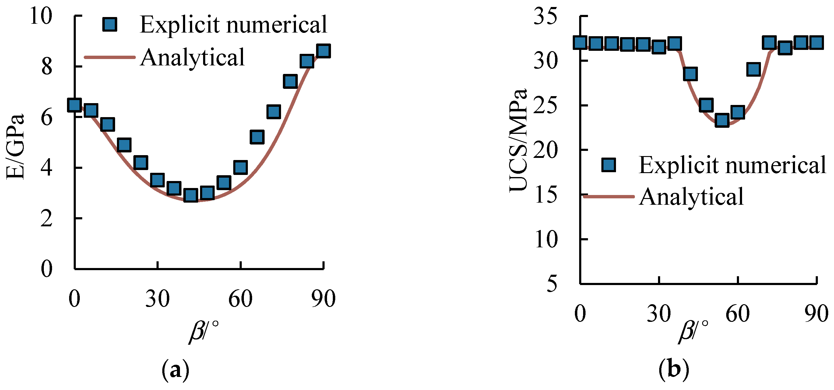
Numerical uniaxial compression tests were performed for various loading angles β for the pillar specimen shown in
Figure 6. The corresponding modulus and strength results are plotted in
Figure 7. The comparison shows that the anisotropy characteristics of deformation and strength expressed by the explicit model are the same as the analytical results, and the magnitudes are well-matched, indicating that the explicit approach successfully simulates the anisotropy of the mechanical properties of quartz mica schist.
4.2. Implicit Approach
Unlike the explicit approach, when the implicit method is adopted a specialized constitutive model is required. Traditionally, it is difficult to simultaneously consider the anisotropy of deformation and the anisotropy of strength. A practical way is to use the anisotropic elasticity model when the anisotropy of deformation needs to be prioritized and to use an anisotropic strength model (e.g., the ubiquitous-joint model [
13]) when the anisotropy of strength needs to be specifically considered.
As an attempt to address these issues, a “jointed rock mass” constitutive model was introduced here [
14] to simulate both the anisotropy of deformation and strength of the quartz mica schist simultaneously. Its main features are as follows:
- (1)
In terms of deformation anisotropy, the rock mass is regarded as a combination of a rock matrix and fractures. The matrix is regarded an isotropic elastic material, and its deformation behavior is dominated by two parameters, the modulus and Poisson ratio. The fractures are considered implicitly as penetrated structure planes, the deformation behavior of which is dominated by three parameters: Fracture spacing, fracture normal stiffness, and fracture shear stiffness. The physical meanings of those parameters are practical, which makes this model very convenient to use.
- (2)
In terms of strength anisotropy, for the rock matrix and fractures, the strength characteristics can be considered separately, i.e., the rock and fractures have their own cohesion, friction angle, tensile strength, and other strength parameters.
- (3)
With the above assumptions, this model is feasible to consider multiple fracture sets. When only one fracture set was considered, the current constitutive model degenerates into a layered rock mass model, making it suitable to describe the anisotropic characteristics of the quartz mica schist in the current study.
- (4)
The FLAC3D code was used to perform the implicit numerical simulation. The model setup in the implicit numerical model was consistent with that of the analytical solution and explicit numerical model, i.e., the dimensions of the pillar specimen were 0.1 × 0.1 × 0.2 m and the schistosity formation was implicitly simulated with the “jointed rock mass” constitutive model, the parameters of which follow those listed in
Table 3. The constructed implicit model is shown in
Figure 8.
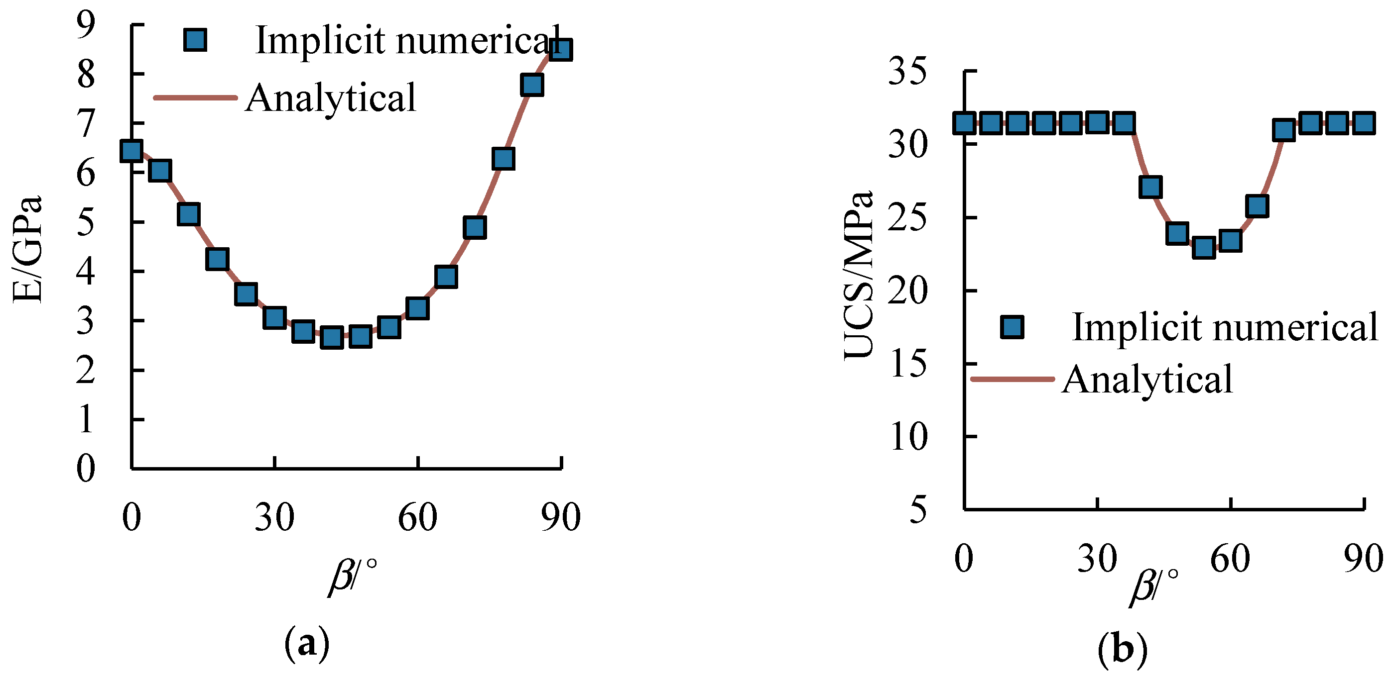
Numerical uniaxial compression tests were performed for various loading angles β for the pillar specimen shown in
Figure 8. The corresponding modulus and strength results are plotted in
Figure 9. The comparison results show a satisfactory match with the analytical results, and the agreement between the implicit model and the analytical solution appears to be better than for the explicit model.
4.3. Discussion
Here, we discuss the two numerical approaches used to select the most suitable method for use in a practical numerical simulation of the schist rock
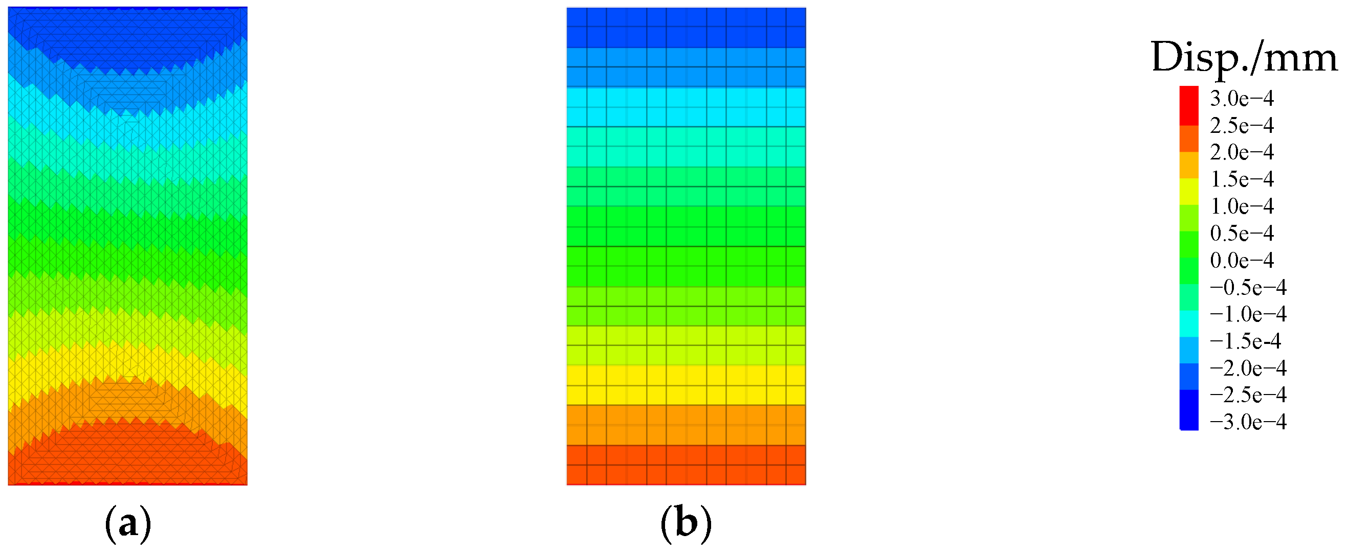
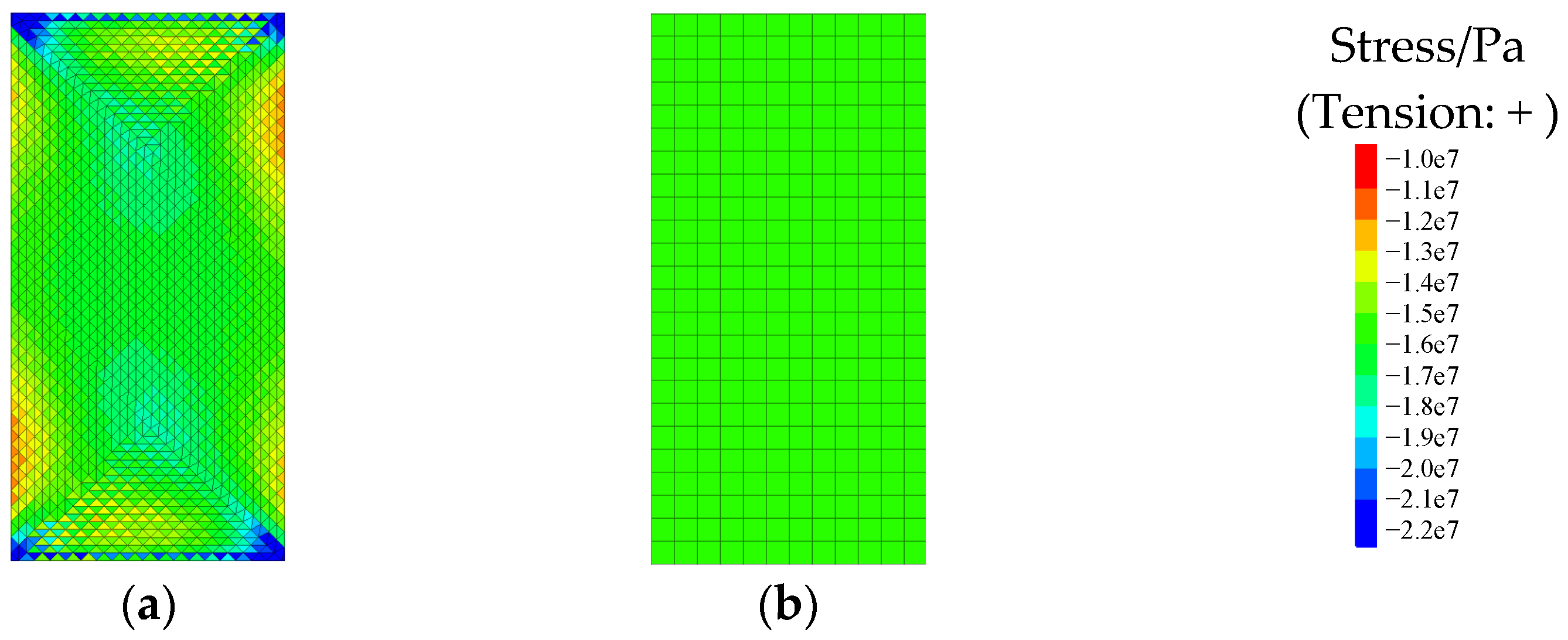
Figure 10 shows the deformation contour of the pillar specimen for the two approaches under the same loading conditions. The numerical simulation test of the two approaches both adopt the displacement servo control mechanism in the uniaxial loading process, and the lateral deformation of the ends of the specimen were freed to simulate a smooth loading surface.
By comparing the deformation contour in
Figure 10, one can notice the unreasonable deformation at the end portion of the explicit approach. The reason for this abnormal phenomenon for the explicit approach is due to the explicit expression of the schistosity formation with penetrated fracture planes. The penetrated fracture planes at the end of the surface were “locked” by the displacement servo control mechanism, meaning that no shear deformation of the penetrated fracture planes at the end surface could occur. Eventually, this led to the incorrect deformation contour at the end portion of the specimen. By contrast, a reasonable deformation contour was produced by the implicit approach.
Figure 11 shows a comparison of the vertical stress within the specimen using the two approaches under the same loading conditions. As can be seen in
Figure 11a, despite the uniform stress field (≈16 MPa) in the central portion of the specimen, the stress contour of the explicit specimen was warped at the ends and unreasonable stress concentrations can be found. By contrast, the stress within the implicit model was uniformly distributed.
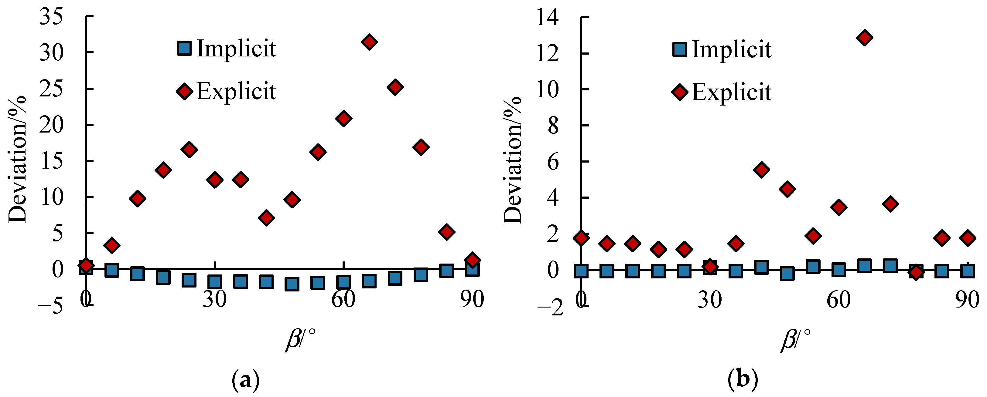
To compare the accuracy of the two approaches, the simulation results of the two methods at different loading angles
were compared with the analytical solution, and the corresponding deviations are shown in
Figure 12. The predicted values using the explicit model are always greater than the analytical solution. Additionally, the deviations of the explicit result are more significant at a larger loading angle because more fractures were “locked” at the ends when the loading angle was large.
The ideal practical numerical simulation method for schist rock should be able to obtain robust results at various scales. Since the purpose of investigating the anisotropy of the mechanical properties of quartz mica schist is to understand its effect on rock engineering, the particle numerical method of simulating the schist rock should be capable of carrying out numerical simulations at a scale appropriate for engineering works. Therefore, the performance of the two approaches at different calculation scales is discussed here.
For the explicit approach, the rock matrix is represented by isotropic finite-difference zones, so it has no scale dependence. However, the schist fractures are represented by contact elements, and the spacing of joint elements cannot be changed once the parameters are calibrated. Therefore, when simulating a large-scale rock excavation, the large number of fracture planes will present a huge computational burden, since the spacing of the fracture planes is usually very small. For the implicit approach, the combination of the rock matrix and the schist fractures are simulated with finite-difference zones alone. Thus, there is no scale dependence except the numerical error brought about by the change of the element size.
To illustrate the size independence of the implicit approach, the simulated results of the uniaxial loading numerical experiment under various unit sizes were calculated, and the corresponding unit number covers the size range of 4.2 to 25 mm. Besides a small amount of error, the simulation results under various element sizes were almost the same, as shown in
Figure 13.
Based on the above comparisons, we selected the implicit approach as the more practical numerical method to model the anisotropy of mechanical parameters of schist rock. In the next section, we demonstrate the applicability of this practical numerical method using an engineering case study.
5. Case Study
We conducted numerical modeling of the CPD-1 adit tunnel to demonstrate the feasibility of the proposed practical numerical approach. In the numerical simulation, the surrounding rock mass was modeled with finite-difference zones that follow the constitutive model described in
Section 4.2.
It is known that the mechanical parameters obtained from an indoor rock test cannot be directly used to represent that of an engineering rock mass. The mechanical parameters of the rock mass require a back-analysis process based on engineering monitoring data.
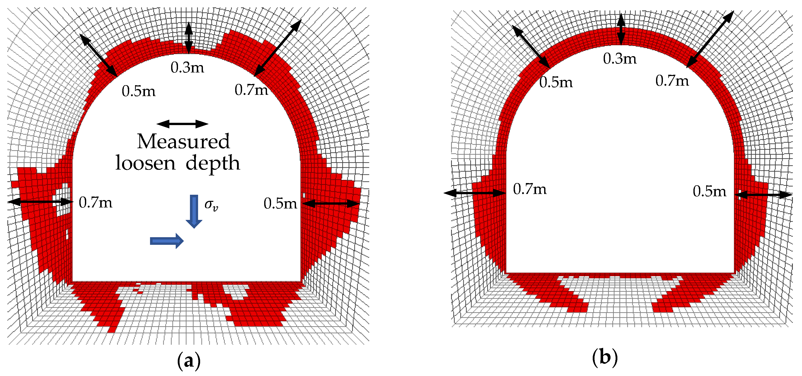
The back-analysis of the rock mass’s mechanical parameters was based on a specially designed wave velocity test. Boreholes were drilled at specific locations of the adit tunnel, and the depth of the loose rock zone was determined based on a sonic test in these boreholes, as shown as the black arrows in
Figure 14. The loose rock depths were asymmetric due to the anisotropic nature of the schist rock.
Assuming that the schistosity formation maintains the parameters of the mini-fractures in
Table 3, the back-analyzed parameters of the rock mass matrix could be obtained (
Table 4).
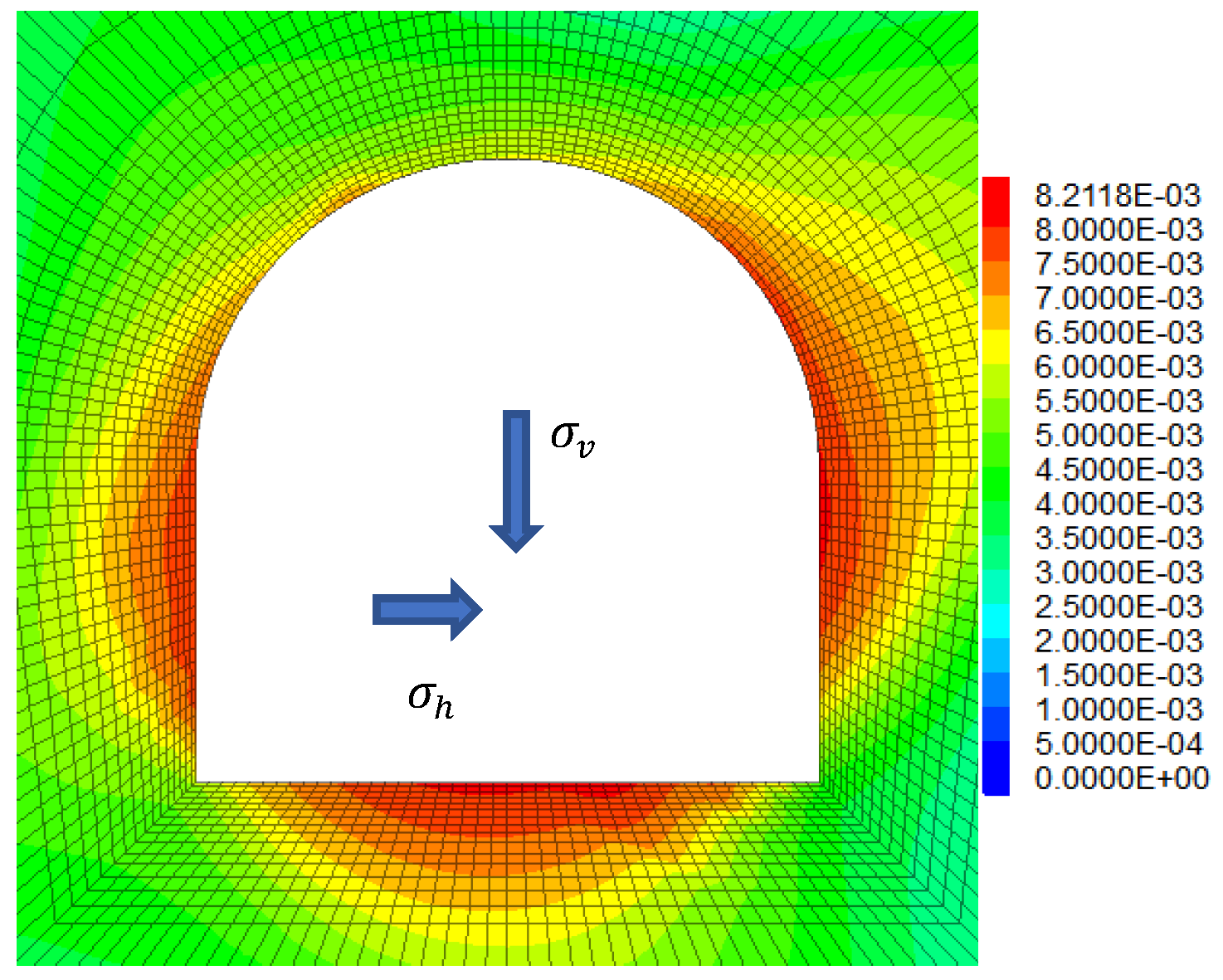
The modeled excavation behavior of the CPD-1 adit tunnel is shown in
Figure 14a and
Figure 15. The simulated results revealed that the plastic zone depth in the left wall foot and the right arch were relatively large, which is consistent with the measured loose material depth, especially the loose material depth of the side walls. Despite the significant difference in the loose material depth in the top arch of the tunnel, the results correctly show the distribution pattern of the loose material zones.
As a comparison,
Figure 14b shows the loose material zones predicted by the traditional isotropic constitutive model. The calculated plastic zone is small in depth and symmetrical, indicating that the isotropic model cannot reveal the anisotropic mechanical behavior of the quartz mica schist.
6. Conclusions
In this paper, we used the anisotropy of the mechanical behavior of quartz mica schist in the Danba Hydropower Project, China, as a case study. The practical numerical simulation approach we developed to determine the anisotropy in the schist rock was discussed, and the following conclusions have been drawn:
- (1)
For the Danba Hydropower Project, the anisotropy of the quartz mica schist rock was found in the spalling of the surrounding rock mass of the adit tunnel and was detected during in situ and laboratory rock tests. A modulus anisotropic ratio of three was obtained via the in situ test, suggesting significant anisotropy exists in the Danba schist.
- (2)
The multi-angle loading laboratory test results showed that the modulus of the schist was at the minimum when the loading direction was oblique to the schistosity formation, while the modulus reached its maximum value when the loading direction was parallel to the schistosity formation. This trend holds true for the strength of the schist. Additionally, the failure mode was controlled by the angle between the schistosity formation and the loading direction.
- (3)
When the quartz mica schist is regarded as a mini “layered fractured rock mass" composed of the rock matrix and schistosity, its deformation and strength anisotropy can be expressed accurately using the equivalent modulus calculation method of fractured rock mass and the strength theory for a single weak plane.
- (4)
Both the explicit and implicit approach could effectively represent the anisotropy of the mechanical properties of quartzite mica schist. Moreover, each approach has its own pros and cons. The advantage of the explicit approach is that it is easy to implement, but, when simulating a large-scale excavation, the densely cut layers of the schistosity become a computational burden. By contrast, the implicit approach requires a sophisticated anisotropic constitutive model. However, the implicit approach is free from scale dependence of the numerical element and has good practical capabilities for the numerical simulation of large-scale excavation at an engineering relevant scale.
- (5)
The numerical modeling of the CPD-1 adit tunnel was conducted to demonstrate the proposed practical numerical approach. The predicted results of the proposed approach are consistent with the measured loose depth of surrounding rock obtained through sonic testing, which reflects the controlling effect of schistosity in quartzite mica schist on the failure and deformation pattern of the surrounding rock mass.
- (6)
The main limitation of this study is the lack of consideration given to the post-peak behavior in the anisotropy of the schistosity. In addition, the mechanical behavior of anisotropic rock would be likely to vary under high level of confinement. Those two issues should be addressed in further investigations on the anisotropy of mechanical parameters of schist rock.
Author Contributions
The paper was written by Z.C. under the help of Q.S. and G.Z. The numerical model test was carried out by Q.L. under the help of G.Z. All authors have read and agreed to the published version of the manuscript.
Funding
This work is supported by the National Key Research and Development Program of China (no. 2016YFC0401803), the National Natural Science Foundation of China (no. 41672319, no. 51779253, 41902288, and 52079133), Major project of the National Basic Research Program of China (no. 51991393), the Key Laboratory for Geo-Mechanics and Deep Underground Engineering, China University of Mining & Technology (no. SKLGDUEK1912), CRSRI Open Research Program (program SN: CKWV2019746/KY), MOE Key Lab of Disaster Forecast and Control in Engineering, Jinan University (no. 20200904002), and the Youth Innovation Promotion Association CAS.
Institutional Review Board Statement
Not applicable.
Informed Consent Statement
Not applicable.
Data Availability Statement
The data presented in this study are available on request from the corresponding author.
Conflicts of Interest
The authors declare no conflict of interest.
References
- Goodman, R.E. Introduction to Rock Mechanics, 2nd ed.; John Wiley & Sons: New York, NY, USA, 1989; pp. 20–25. [Google Scholar]
- Amadei, B.; Savage, W.Z. Effect of joints on rock mass strength and deformability. In Comprehensive Rock Engineering—Principles, Practice, and Projects; Hudson, J.A., Ed.; Pergamon Press: Oxford, UK, 1993; Volume 1. [Google Scholar]
- Li, C. A method for graphically presenting the deformation modulus of jointed rock masses. Rock Mech. Rock Eng. 2001, 34, 67–75. [Google Scholar] [CrossRef]
- Jaeger, J.C.; Cook, N.G. Fundamentals of Rock Mechanics, 2nd ed.; Chapman and Hall: New York, NY, USA, 1979; pp. 145–156. [Google Scholar]
- Tien, Y.M.; Kuo, M.C. A failure criterion for transversely isotropic rocks. Int. J. Rock Mech. Min. Sci. 2001, 38, 399–412. [Google Scholar] [CrossRef]
- Duveau, G.; Shao, J.F. A modified single plane of weakness theory for the failure of highly stratified rocks. Int. J. Rock Mech. Min. Sci. 1998, 35, 807–813. [Google Scholar] [CrossRef]
- Hoek, E.; Brown, E.T. Underground Excavations in Rock; The Institution of Mining and Metallurgy: London, UK, 1980; pp. 200–210. [Google Scholar]
- Huang, S.L.; Xu, J.S.; Ding, X.L.; Wu, A.Q. Study of layered rock mass composite model based on characteristics of structural plane and its application. Chin. J. Rock Mech. Eng. 2010, 29, 743–757. [Google Scholar]
- Huang, S.L.; Ding, X.L.; Wu, A.Q.; Lu, B.; Zhang, Y.-H. Study of multi-joint constitutive model of layered rockmass and experimental verification. Chin. J. Rock Mech. Eng. 2012, 31, 1627–1636. [Google Scholar]
- Qi, Y.; Indraratna, B.; Coop, M.R. Predicted behavior of saturated granular waste blended with rubber crumbs. ASCE Int. J. Geomech. 2019, 19, 04019079. [Google Scholar] [CrossRef]
- Qi, Y.; Indraratna, B. Energy-based approach to assess the performance of a granular matrix consisting of recycled rubber, steel furnace slag and coal wash. J. Mater. Civ. Eng. 2020, 32, 04020169. [Google Scholar] [CrossRef]
- Zhang, Y.; Zhou, H.M.; Zhong, Z.W. In-situ rock masses triaxial test system YXSW–12 and its application. Chin. J. Rock Mech. Eng. 2011, 30, 2313–2320. [Google Scholar]
- Wang, T.; Huang, T. A constitutive model for the deformation of a rock mass containing sets of ubiquitous joints. Int. J. Rock Mech. Min. Sci. 2009, 46, 521–551. [Google Scholar] [CrossRef]
- Agharazi, A.; Martin, D.; Tannant, D. Jointed Rock: A Three-Dimensional Equivalent Continuum Model for Systematically Jointed Rock Masses; Itasca Houston Inc.: Houston, TX, USA, 2014. [Google Scholar]
Figure 1.
In situ observation of the anisotropy of Danba schist: (a) Stereonet plot of the schistosity in the Danba schist (lower-hemisphere, equal-angle projection); (b) plan view of the filming locations in the CPD-1; (c) the stable surrounding rock mass in the CPD-1 adit; (d) the spalling surrounding the rock mass in the auxiliary adit.
Figure 2.
In situ triaxial test of the schist rock: (a) Hand carving the in situ triaxial test specimen; (b) cubic specimen ready for test; (c) cubic specimen following test.
Figure 2.
In situ triaxial test of the schist rock: (a) Hand carving the in situ triaxial test specimen; (b) cubic specimen ready for test; (c) cubic specimen following test.
Figure 3.
Microscopic image of the Danba quartz mica schist: (a) Parallel to schistosity; (b) perpendicular to schistosity.
Figure 3.
Microscopic image of the Danba quartz mica schist: (a) Parallel to schistosity; (b) perpendicular to schistosity.
Figure 4.
Modulus E and uniaxial compressive strength (UCS) of various loading angle and the corresponding analytical solution. (a) Convention of the loading angle; (b) modulus E; (c) uniaxial compressive strength.
Figure 4.
Modulus E and uniaxial compressive strength (UCS) of various loading angle and the corresponding analytical solution. (a) Convention of the loading angle; (b) modulus E; (c) uniaxial compressive strength.
Figure 5.
Images and sketches of the failure mode at various loading angles: (a) = 90°; (b) = 45°; (c) = 0°.
Figure 5.
Images and sketches of the failure mode at various loading angles: (a) = 90°; (b) = 45°; (c) = 0°.
Figure 6.
Numerical specimen of the explicit approach.
Figure 6.
Numerical specimen of the explicit approach.
Figure 7.
Simulated results of the explicit approach. (a) Modulus E; (b) uniaxial compressive strength (UCS).
Figure 7.
Simulated results of the explicit approach. (a) Modulus E; (b) uniaxial compressive strength (UCS).
Figure 8.
Numerical specimen of the explicit approach.
Figure 8.
Numerical specimen of the explicit approach.
Figure 9.
Simulated results of the implicit approach. (a) Modulus E; (b) uniaxial compressive strength (UCS).
Figure 9.
Simulated results of the implicit approach. (a) Modulus E; (b) uniaxial compressive strength (UCS).
Figure 10.
Displacement contour via respective methods ( = 45°). (a) Explicit; (b) implicit.
Figure 10.
Displacement contour via respective methods ( = 45°). (a) Explicit; (b) implicit.
Figure 11.
Stress contour via respective methods ( = 45°). (a) Explicit; (b) implicit.
Figure 11.
Stress contour via respective methods ( = 45°). (a) Explicit; (b) implicit.
Figure 12.
Deviation of simulation results vs analytical value. (a) Modulus E; (b) uniaxial compressive strength (UCS).
Figure 12.
Deviation of simulation results vs analytical value. (a) Modulus E; (b) uniaxial compressive strength (UCS).
Figure 13.
Simulated result with different element size. (a) Modulus E; (b) uniaxial compressive strength (UCS).
Figure 13.
Simulated result with different element size. (a) Modulus E; (b) uniaxial compressive strength (UCS).
Figure 14.
Excavation-induced failure zone of CPD-1: (a) with the isotropic constitutive model; (b) with the anisotropic constitutive model.
Figure 14.
Excavation-induced failure zone of CPD-1: (a) with the isotropic constitutive model; (b) with the anisotropic constitutive model.
Figure 15.
Excavation-induced displacement contour of CPD-1 predicted with the anisotropic constitutive model.
Figure 15.
Excavation-induced displacement contour of CPD-1 predicted with the anisotropic constitutive model.
Table 1.
Test results via plate loading test.
Table 1.
Test results via plate loading test.
| Location | Description | Strength (Peak) | Strength (Resident) | Modulus |
|---|
| c/MPa | /°
| c/MPa | /°
| E/GPa |
|---|
| Floor | Perpendicular to schistosity | 1.92 | 51.12 | 0.33 | 22.78 | 19.82 |
| Side wall | Parallel to schistosity | 0.20 | 22.78 | 0.18 | 16.17 | 1.12 |
Table 2.
Results via in situ true triaxial test.
Table 2.
Results via in situ true triaxial test.
| Description | Strength | Modulus |
|---|
| c/MPa | /°
| E/GPa |
|---|
| Loosen | Perpendicular to schistosity | 1.2–1.5 | 38.66–45 | 2–3 |
| Parallel to schistosity | / | / | 4–6 |
| Intact | Perpendicular to schistosity | 1.5–1.8 | 45–50.19 | |
| Parallel to schistosity | / | / | 10–12 |
Table 3.
Calibrated parameters of the schist rock.
Table 3.
Calibrated parameters of the schist rock.
| Material | Parameters and Magnitudes |
|---|
| Rock matrix | Modulus/GPa | 8.5 | Poisson’s ratio | 0.21 |
| c/MPa | 7 | /° | 42.0 |
| Fractures | Normal stiffness/(GP/m) | 5280 | Shear stiffness/(GP/m) | 206 |
| Spacing/m | 0.005 | c/MPa | 8 |
| /° | 20.0 | / | / |
Table 4.
Rock mass matrix properties of CPD-1 tunnel via back analysis.
Table 4.
Rock mass matrix properties of CPD-1 tunnel via back analysis.
| Modulus/GPa | Poisson’s Ratio | c/MPa | /°
|
|---|
| 8 | 0.25 | 2.4 | 35 |
| Publisher’s Note: MDPI stays neutral with regard to jurisdictional claims in published maps and institutional affiliations. |
© 2021 by the authors. Licensee MDPI, Basel, Switzerland. This article is an open access article distributed under the terms and conditions of the Creative Commons Attribution (CC BY) license (http://creativecommons.org/licenses/by/4.0/).


