Article

Evaluation and Improvement of PCM Melting in Double Tube Heat Exchangers Using Different Combinations of Nanoparticles and PCM (The Case of Renewable Energy Systems)

by
Ali Motevali
1,*,
Mohammadreza Hasandust Rostami
2,
Gholamhassan Najafi
2 and
Wei-Mon Yan
3
1
Department of Mechanics of Biosystem Engineering, Sari Agricultural Sciences and Natural Resources University, Sari 48181-66996, Iran
2
Department of Mechanics of Biosystems Engineering, Tarbiat Modares University, Tehran 14115-111, Iran
3
Department of Energy and Refrigerating Air-Conditioning Engineering, National Taipei University of Technology, Taipei 10608, Taiwan
*
Author to whom correspondence should be addressed.
Sustainability 2021, 13(19), 10675; https://doi.org/10.3390/su131910675
Submission received: 21 August 2021 / Revised: 10 September 2021 / Accepted: 20 September 2021 / Published: 26 September 2021

Abstract

:
In this work, the melting process of phase change material (PCM) in double tube heat exchangers was investigated and evaluated through the use of different combinations (1, 2, 3% Nano-Enhanced PCM and 1, 3, 5% Nano-HTF) of GQD, as well as SWCNT nanoparticles and PCM (RT82). In this study, the effect of three different methods, namely the dispersion of nanoparticles in PCM (nano-enhanced PCM), the dispersion of nanoparticles in HTF (nano-HTF), and the simultaneous dispersion of nanoparticles in PCM and HTF (nano-enhanced PCM, nano-HTF) concerning the nanoparticles participation in the thermal energy storage system in a double tube heat exchanger was evaluated. Other effective factors, such as the inlet fluid temperature, different Reynolds numbers, fin as well as new parameter of pipe, and fin thickness were also evaluated. The results showed that the highest effect of different parameters on the PCM melting process was related to the 1% nano-HTF and 3% nano-enhanced PCM nanoparticles of SWCNT, which decreased the PCM melting rate by about 39%. The evaluation of the effect of pipe and fan thickness also showed that the melting rate improved by 31% through reducing the thickness of the HTF fin and pipe. In general, the current study followed two purposes first, to examine three methods of the dispersion of nanoparticles in the thermal energy storage system; second, to reduce the thickness of the tube and fin. Findings of the study yielded positive results.

1. Introduction

Today, due to the increase in energy consumption and reduction of non-renewable energy sources, the use of modern methods to increase efficiency and prevent energy waste is of great importance. Thermal energy storage systems (TES) are among the leading methods to improve the thermal efficiency and store thermal energy. Nowadays, the phase change materials (PCMs) have high efficiency in thermal systems, as they are categorized by high latent heat, which can be effective in storing thermal energy. One of the important advantages of PCM is its high heat storage density at a constant temperature and volume. The absorption of heat by the afore-mentioned material is called the melting state, and the process of giving heat by this material to the environment is called the solidification state. As a result of this heat exchange over time, the phase changes from solid to liquid, and vice versa. Much research on PCMs has been done by researchers in different conditions, which shows that the use of PCMs has been widely addressed in various industries and scientific research when it comes to thermal storage systems.
Rostami et al. [1] conducted a review of melting and freezing processes of PCM/nano-PCM and their application in energy storage system. They indicated that the PCMs can improve the thermal performance and reduce energy consumption. The preparation methods and the thermal properties of the microencapsulated phase change materials (MEPCMs) were reviewed in detail by Huang et al. [2]. Besides, Huang et al. indicated that the MEPCMs can provide enormous potentials for applications of cooling and heating in buildings, textiles, and MEPCM slurry fields. Kalapala and Devanuri [3] provided a detailed review on the thermal storage of PCM in different heat exchangers. In addition, the key parameters on the thermal efficiency of PCM-based heat exchanger were examined. Medrano et al. [4] analyzed the thermal properties of a number of heat exchangers under different conditions in thermal energy storage unit during the melting and solidification periods. The melting and solidification characteristics for erythritol in a shell and multi-finned tube thermal storage system have been experimentally conducted by Anish et al. [5]. Trp [6] examined the melting and solidification of a PCM in a thermal energy storage system. The results showed that the velocity of the working fluid quickly reached a steady state, but the temperature element did not reach a steady state after a while, because due to the large Prandtl number, the amount of heat transfer from the working fluid to the PCM decreases and is transferred to the lower part of the working fluid. The solidification process of PCM and NEPCM in the triplex-tube latent heat thermal system was investigated by Alizadeh et al. [7]. They found that the V-shaped fin causes a faster solidification process than the nanoparticle dispersion. Ettouney et al. [8] performed an experimental study on the melting and solidification of PCM in the shell and tube heat exchanger, in which the working fluid moves in tubes and the PCM is placed inside the shell. This research indicated that natural convection in shell side has a more important role in the process of melting and solidification of PCM when compared to the conduction of heat transfer. Rahimi et al. [9] conducted an experimental study on the effect of fin and mass flow rate on melting and solidification of the PCM in a thermal energy storage system. The results of their research showed that the use of fin increases the average temperature of the PCM and reduces the melting time of this material, which is more noticeable in the melting process compared to the flat tubular heat exchanger. Thermal efficiency of a novel thermal energy storage unit with PCM was experimentally and numerically examined by Lin et al. [10]. Results disclosed that the novel energy storage unit has good thermal performance with PCM.
Regin et al. [11] investigated the process of melting the PCM in a heat storage system using the encapsulated tanks. The results of their research showed that the range of temperature changes of the melting phase of the PCM, the radius of the encapsulated tanks, and the inlet temperature of the working fluid has a different effect on the melting rate process. Kibria et al. [12] performed an experimental and numerical study on the factors affecting the melting and solidification of the PCM in a shell and tube heat exchanger, in which the working fluid was in the pipes and the PCM was in the shell part. In this study, they investigated the flow characteristics, such as the inlet fluid temperature and mass flow rate, together with the geometric characteristics of the system, such as the pipe thickness and radius. The results of their research showed that the temperature of the inlet fluid and the radius of the pipes have a more significant effect than the other two parameters. A numerical study on the process of melting and solidification of the PCM in a double tube heat exchanger was conducted by Ismail et al. [13]. Their results showed that with further reduction of the inlet temperature of the working fluid, a greater amount of PCM is frozen. Moreover, increasing the mass flow rate of the working fluid accelerates the melting and solidification process of the PCM, but it has a much smaller effect when reducing the inlet temperature of the working fluid. Basal and Unal [14] evaluated the melting and solidification process of PCM in the triplex tube heat exchanger. They assessed the effect of inlet temperature, inlet flow rate, and some geometric properties such as the pipe radius. Their results revealed that by using a triplex tube heat exchanger, compared to the double tube heat exchangers, the melting time of PCM is reduced by 6. A case study on the melting and solidification of RT82 as a PCM was performed by Hosseini et al. [15]. The predicted liquid fraction and temperature contours show that at points close to the working fluid, the liquid fraction contours expand outwards. Furthermore, the experimental results of this research represent that a 10 °C increase in the inlet temperature improves the theoretical efficiency of the melting process by 7%. Accordingly, Hosseini et al. [16] carried out experimental research on the thermal properties of heat transfer fluid and PCM. The obtained conclusions of their study indicated that, by increasing the inlet temperature of the working fluid from 70 °C to 80 °C, the time required to melt the PCM is reduced by 37%.
The characteristics of the melting and solidification of PCM in a triplex tube heat exchanger with surfaces expanded internally and externally were investigated by Al-Abidi et al. [17]. Two parameters of mass flow rate and fluid temperature entering the system were evaluated in this work. The results manifested that the changes in fluid inlet temperature had a greater effect on the charge and discharge process than the other parameters. Esapour et al. [18,19] carried out a numerical investigation on the melting and solidification of PCM through increasing the internal tubes in a shell and tube heat exchanger. The predictions showed that by increasing the number of tubes to 4, the melting time is reduced, because the residence time of the fluid inside the shell containing the PCM and the contact surfaces is increased. The results also showed that the effect of increasing the inlet temperature of the fluid has a greater effect on the melting process than the mass flow parameter. The effects of the position of the shell and tube heat exchanger in relation to the horizon in the process of melting and solidification of the PCM were investigated by Kousha et al. [20]. The results presented that the horizontal position of the heat exchanger in the melting process is more effective in heat transfer rate, while in the solidification process, the vertical position of the heat exchanger has a significant effect on transferring to the PCM. Mat et al. [21] numerically investigated the effects of three different methods on the melting of PCM. The predicted results indicated that in the case of no blade, the melting time is reduced by 43%. Adine and Qarnia [22] evaluated and tested the effect of multiple phase change materials with different phase change temperatures in a shell and tube heat exchanger. The double, multiple, and single combinations of PCM in the heat exchanger were examined. The results showed that the binary system of the PCM has a better performance when increasing the mass flow rate of the fluid at a lower fluid inlet temperature. Furthermore, the combination of several PCMs at lower mass flow rate and inlet fluid temperature is more effective in the melting process. Due to the importance of thermal energy storage and its use at the right time, other studies were conducted in this field [23,24]. Kok [25] conducted a study on PCM melting using two types of fins in combination with nanoparticles. The results showed that the use of Fin 1 in combination with PCM and nano PCM for 120 min reduces the melting rate of PCM by 98% and 36%, respectively. Sun et al. [26] investigated the effects of graphite nanoparticles in combination with PCM (nano-enhanced PCM) on the PCM melting process. Their results showed that the combination of nano-PCM reduces the melting rate of PCM by 21% compared to pure PCM, which resulted in 0.06 wt % graphite with 2% oleic acid. Ebadi et al. [27] conducted a research on the PCM melting process with a focus on bio-based PCM and nano-PCM using copper nanoparticles. In this study, they found that the use of 1 wt.% of copper nanoparticles increases the thermal conductivity of PCM by 7.5%, and the melting of PCM improves by 15% using the nano-PCM. Lee et al. [28] evaluated the effect of a porous medium and nanoparticles in combination with the PCM melting and solidification process in a triplex tube heat exchanger. The results showed that the addition of 5% copper nanoparticles (nano-enhanced PCM) in combination with the porous medium reduces the melting time of PCM by 25.9%. Kristiawan et al. [29] conducted a study concerning the effect of nanoparticles on both laminar and turbulent regimes, which clearly showed that in laminar and turbulent currents, the available nanoparticles cause a significant increase in heat transfer. For laminar flow, the numerical results showed that the increase in the heat transfer coefficient of nanofluid is 4.63, 11.47, and 20.20% for nanoparticle loading of 0.24, 0.60 and 1.18 vol.%, respectively.
Other research has also shown that the overall composition of nanoparticles in the base fluid improves the overall heat transfer coefficient [30,31,32,33].
In the present study, the melting process of RT82 as a phase change material in double tube heat exchangers was numerically investigated. In previous research, the combination of nanoparticles with PCM (nano-enhanced PCM (NePCM)) in the chamber around HTF (nano-water or pure water) was widely used to improve the melting and solidification process of PCM, and its effect on the melting process was evaluated. In the present study, three methods of nanoparticles participation in the heat storage system have been used, which means that the combination of nanoparticles with PCM (Nano-Enhanced PCM (NePCM)), participating nanoparticles with HTF (nano-HTF), and the effect of simultaneous participation of nanoparticles in PCM chamber and HTF chamber (nano-enhanced PCM, nano-HTF) in the PCM melting process was evaluated and compared at different percentages and compositions that have not been recently evaluated and studied. In addition to other auxiliary and improving factors in the melting process such as the fin and hybrid nanoparticles, the effect of another factor (pipe and fin thickness) was also examined as a new parameter that has been found to have positive results.

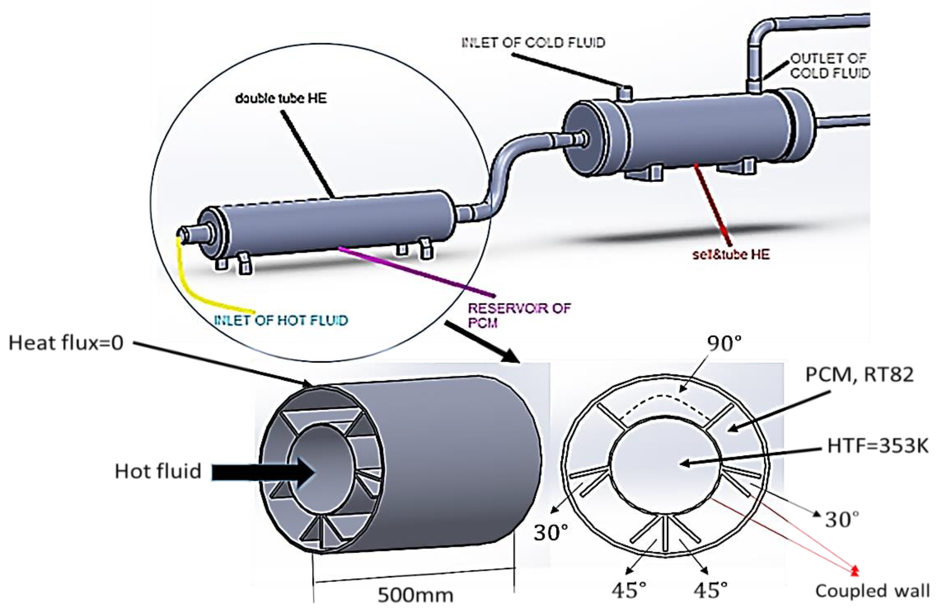
2. Numerical Approach

2.1. Governing Equations

This research was performed using two heat exchangers in series, in which one heat exchanger performs the task of heat conversion and the another heat exchanger conducts thermal storage using a phase change material (PCM). This is done in order to use the primary heat exchanger to perform the cooling cycle of the secondary heat exchanger faster, thus preventing the loss of heat energy in the secondary heat exchanger. The flow of fluid returns from the secondary heat exchanger to the primary heat exchanger and this flow continues until the temperature in the secondary heat exchanger reaches the desired value. The fluid inlet temperature is 375 K, but the average operating temperature during the process is 353 K, which is in the range of PCM melting and freezing temperatures. For this reason, RT82 has been used for this study. This periodic process is repeated regularly until a significant portion of the PCM is melted and pasted. Moreover, the duration of this process is in the range of 30 to 60 min. The two heat exchangers of stainless steel and the fins of copper were selected. External diameter, internal diameter, length and thickness of double tube heat exchanger were 50, 27, 500 and 1 mm, respectively. Moreover, the length and thickness of the blade in the outer part of the inner tube using the response surface method in the best case was obtained equal to 10 and 1 mm, respectively. The working fluid passes through the pipe and the space between the two pipes is filled with RT82 phase change material. The inlet fluid temperature was 353 K and the initial state of the phase change material was solid. Two nanoparticles of graphene quantum dot (GQD) and single-walled carbon nanotubes (SWCNT) with mass fractions of 1, 2, 3 and 5% have been adopted in combination with phase change material and working fluid. Various mass fractions of nanoparticles have also been used to evaluate and compare changes in the PCM melting process over a wider range of results. Figure 1 presents the geometric characteristics of the schematic diagram of the relevant system. Moreover, the thermophysical properties of RT82 phase are shown in Table 1.
It is clearly noted in Figure 1 that the blade angles are set to 30, 45 and 90 degrees, which are obtained by optimizing the response surface methodology. The following governing equations have been used to simulate the process of melting the PCM in a double tube heat exchanger while considering thermal buoyancy effects.
Continuity equation:
· V = 0
Momentum equations:
u t + V · u = 1 ρ ( P + μ 2 u ) + s u v t + V · v = 1 ρ ( P + μ 2 v + ρ β g ( T T r e f ) ) + s v
Energy equation:
h t + ( Δ H ) t + · ( V h ) = · ( k ρ C p H )
The u and v are velocity component terms in the x and y directions, respectively. Enthalpy and pressure are determined using h, P respectively. Momentum sink term is expressed using Su and Sv [34,35] as follows:
s u = C ( 1 λ ) 2 u λ 3 + ε s v = C ( 1 λ ) 2 v λ 3 + ε
In above equations, C represents the mushy zone constant in the PCM, which is located between the 105–106 range, and in this study, the number 105 has been selected due to its good compatibility with Mahdi et al. [36]. ε is a small amount to avoid dividing by zero h and Δ H are sensible enthalpy and latent heat, respectively. Sensible enthalpy is expressed using Equation (5):
h = h r e f + T r e f T C p d T .
In the above equation, href is reference enthalpy. Moreover, the melting heat based on the latent heat (Γ) is obtained from Equation (6).
Δ H = λ Γ
In the above equation, λ is liquid fraction of PCM that can be defined as follows:
λ = 0 T T s ( T - T s ) / ( T l - T s ) T s < T < T l l T T l
where Tl and Ts are melting temperature and solid temperature of PCM, respectively. To calculate the natural convective heat transfer that is important in the process of melting the PCM, the Bussinesq approximation is adopted, which considers the density of the PCM as constant. To calculate the temperature difference in different areas of the fin, solving the energy equation in the areas related to the blade has been used.
( ρ f i n C p f i n T f i n ) t = ( k f i n T f i n )
The following equation has also been used to calculate the blade fraction [37].
ϕ f = v f v t = i = 1 n ( L i · W i ) b π ( r o 2 r i 2 ) b
where L, b, W, ro, ri, i and n are length of fin, length of heat exchanger, thickness of fin, outer radius of fin, inner radius of fin, an index for number of fin and total number of fin, respectively.
In this work, the effect of nanoparticles in combination with the PCM and the common state has been compared. The following equations are used to calculate the thermophysical properties of the nanoparticles with the PCM.
ρ N E P C M = ( 1 ϕ n ) ρ P C M + ϕ n ρ n
C p N E P C M = ( 1 ϕ n ) ( ρ C p ) P C M + ϕ n ( ρ C p ) n ρ N E P C M
Γ N E P C M = ( 1 ϕ n ) ( ρ Γ ) P C M ρ N E P C M
β N E P C M = ( 1 ϕ n ) ( ρ β ) P C M + ϕ n ( ρ β ) n ρ N E P C M
In above equations, φn is mass fraction of nanoparticles and the NEPCM index is nano-enhanced PCM. The following expressions of dynamic viscosity (μNEPCM) and thermal conductivity of the nano-enhanced PCM (kNEPCM), respectively, have been used [38,39].
μ N E P C M = 0.983 e ( 12.959 ϕ ) μ P C M
k N E P C M = k n + 2 k P C M 2 ϕ n ( k P C M k n ) k n + 2 k P C M + ϕ n ( k P C M k n ) + 5 × 10 4 β k ζ ϕ n ρ P C M C p P C M B T ρ n d n f ( T , ϕ n )
In this work, the effects of Brownian motion and nanoparticle size have been studied so that factor f(T,ϕn) in the thermal conductivity coefficient shows the amount of Brownian motion. In the solid state of the PCM, there is no Brownian motion, but from the mushy zone to the melting zone of the PCM, the Brownian factor plays an effective role. In the process of melting the PCM, the natural convection, along with thermal conductivity, is considered as an effective phenomenon. Moreover, the flow in this process is considered as laminar, transient and incompressible. Some of the problem assumptions are as follows.
(1)
Friction between the nanoparticles and the base fluid is negligible.
(2)
Viscosity dissipation is not considered.
(3)
Volumetric tolerance for melting PCM is assumed to be neglected.
(4)
The temperature difference in the base fluid can be ignored.
(5)
The thermal properties of PCM are assumed to be constant, except for density in the momentum term.

2.2. Initial and Boundary Conditions

In the process of PCM melting, the average of inlet fluid temperature was 353 K and the initial ambient temperature and the temperature of the solid PCM were both set to be 293 K. The inlet flow rate was adjusted so that the Reynolds numbers of 1700, 2500 and 3200 were evaluated, respectively. The external surface of the outer tube of the heat exchanger was considered to be thermally insulated. In this work, two graphene quantum dot nanoparticles and single-walled carbon nanotubes with mass fractions of 1, 3 and 5% in combination with working fluid and mass fractions of 1, 2 and 3% in combination with PCM have been adopted. Furthermore, the effects of finned heat exchanger, finless heat exchanger and the effects of nanoparticles with different mass fractions on PCM melting were investigated. The initial and boundary conditions of this work are schematically shown in Figure 2.

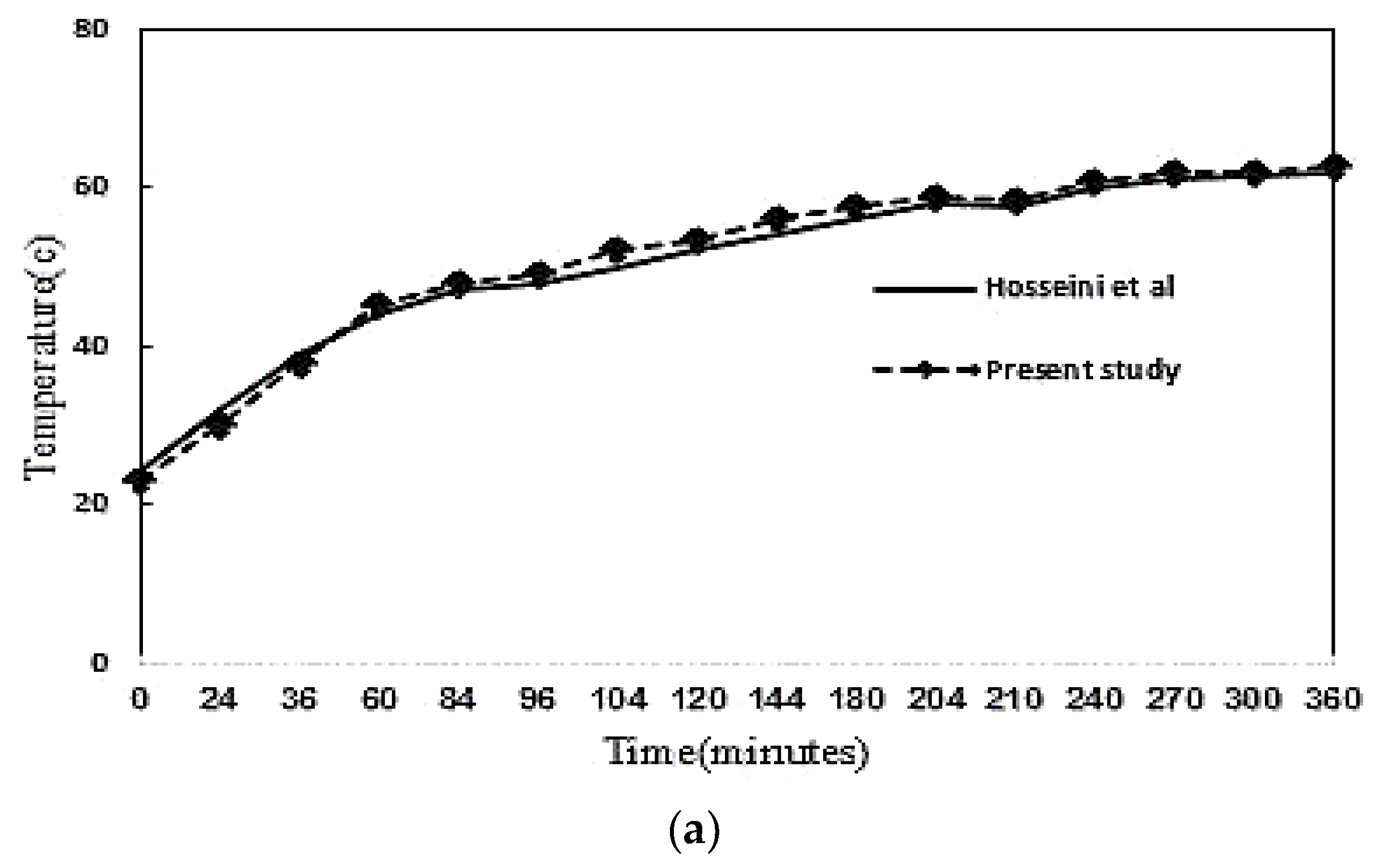
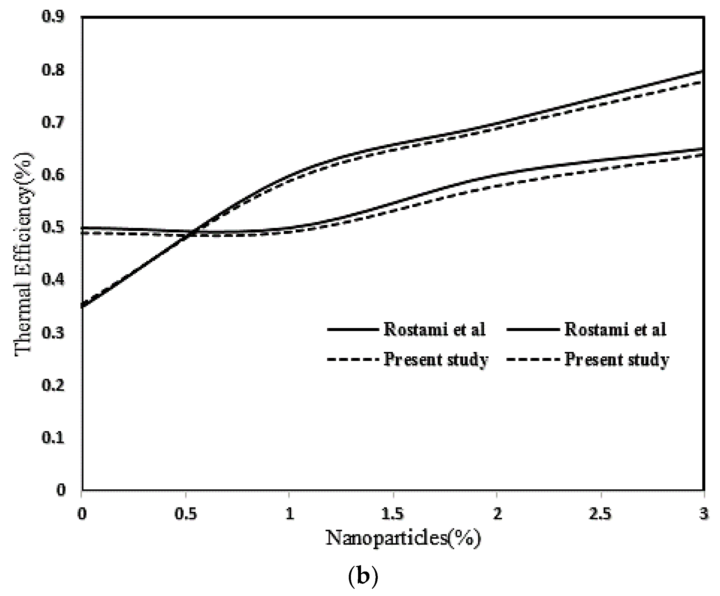
2.3. Numerical Procedure and Validation

In this research, the commercialized software, ANSYS Fluent, which is based on the finite volume method, has been employed to simulate PCM melting in a double pipe heat exchanger. This software uses the enthalpy-porosity technique to solve the governing equations in the melting process. The SIMPLE and PRESTO schemes have also been used for the pressure [40] and QUICK scheme is employed to discretize the governing equations [41]. The grid sizes including N = 500,000, 565,000, 620,000 and 698,000 of cells were examined for numerical solution validation of the independency of grid sizes, for which the system of N = 565,000 was sufficient to obtain accurate and acceptable answers in this study. Time step 0.1s and the number of repetitions are set to 500 for each time step in this study. The convergence index is chosen for the momentum equation and continuity and for the energy equation. Validation of numerical simulation of melting of the PCM was performed in the study. First, an initial run was performed and the predictions were compared with the experimental data of Hosseini et al. [16] and Rostami et al. [42], as shown in Figure 3. It is clearly noted in Figure 3 that a good agreement between the predictions and measured data was found.

3. Result and Discussion

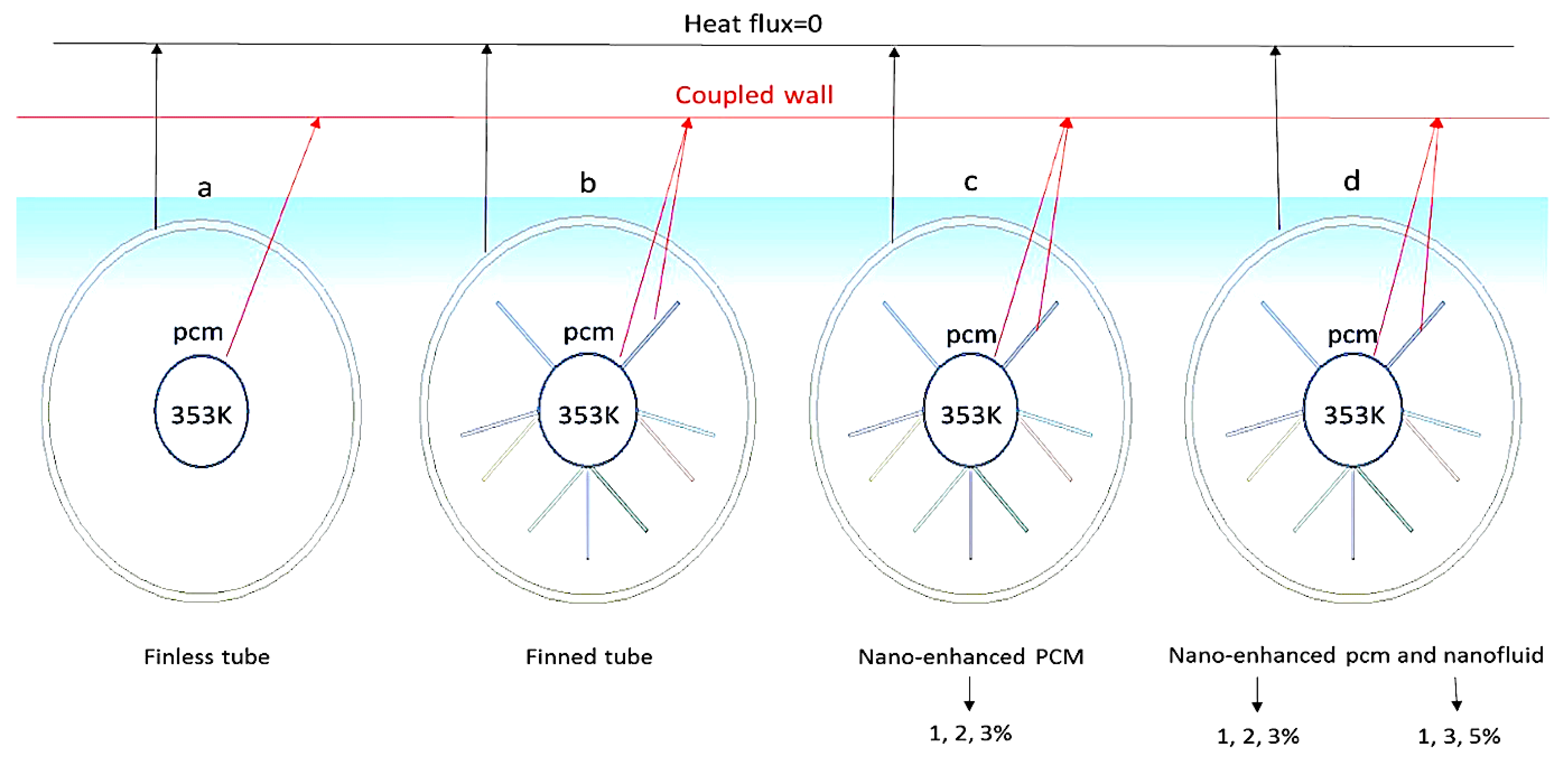
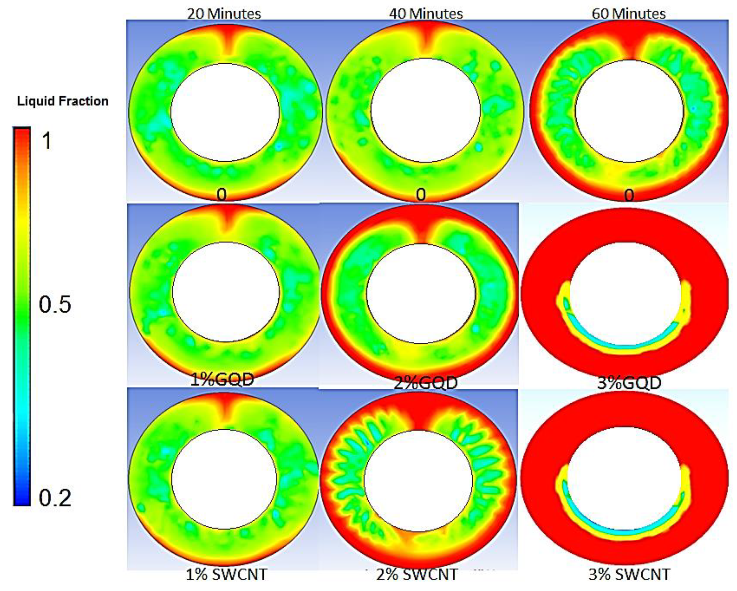
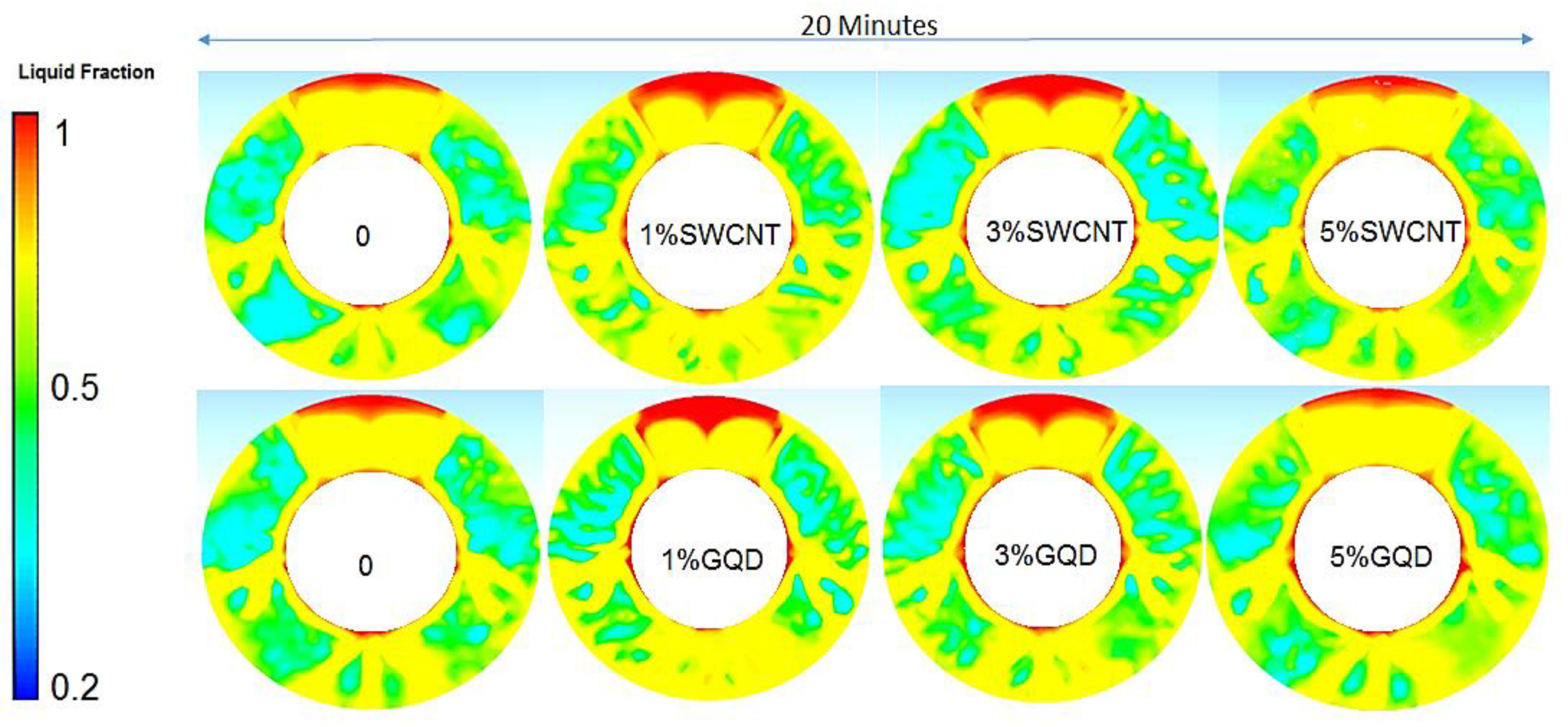
3.1. Effect of Nanoparticles (Nano-Enhanced PCM) on PCM Melting Process

As can be seen from Figure 4, the melting process of the phase change material in a double tube heat exchanger without fin blade was evaluated using mass fractions of 1, 2 and 3% in combination with the PCM (nano-enhanced PCM) over a period of 60 min. The reason for the low time of the process of melting the PCM is that in this system, another heat exchanger was used at the same time to cool the desired fluid according to its function in industry. It is also noted in Figure 4 that the conduction heat transfer creates a mushy area around adjacent points of the heat transfer fluid (HTF). However, with increasing melting process and creating a mushy area around the central tube, convective heat transfer and natural convection phenomenon dominate the conduction heat transfer (due to buoyancy force and density gradient) and heat ascends to the upper hemisphere of the heat exchanger [43].
Furthermore, with the increase of this process and heat circulation, it moves to the lower points. In addition, by increasing the mass fraction of nanoparticles from 1% to 3%, the conduction heat transfer due to the high thermal conductivity of the nanoparticles increases and causes the phase change material (PCM) to melt faster [44]. Approaching 60 min and decreasing the temperature of the heat transfer fluid (due to heat exchange in the secondary shell and tube heat exchanger), the melting process of the PCM takes place slowly, and a spherical line is created under the tube carrying the working fluid, which does not have a significant effect on the melting process.

3.2. Effect of Fin Tubes and Nanoparticles (Nano-HTF) on the PCM Melting Process

The effects of different mass fractions of nanoparticles on the PCM melting process are shown in Figure 5. As can be seen from the figures, the best melting performance is obtained at a mass fraction of 1% SWCNT (nano-HTF). This is because it has increased the conduction heat transfer coefficient, but at higher mass fractions, PCM melting has not changed significantly, because increasing the mass fraction of nanoparticles increases the density of HTF and decreases the buoyancy force, thus reducing natural convection. Furthermore, the left and right points of the HTF demonstrate less melting. This is because the presence of side fins has prevented the natural convection due to PCM melting at the lower points of the heat transfer, while the highest amount of melting has occurred in the upper hemisphere of the heat transfer and between the two fins, which was due to the heat transfer from HTF Center [42,43,44,45].

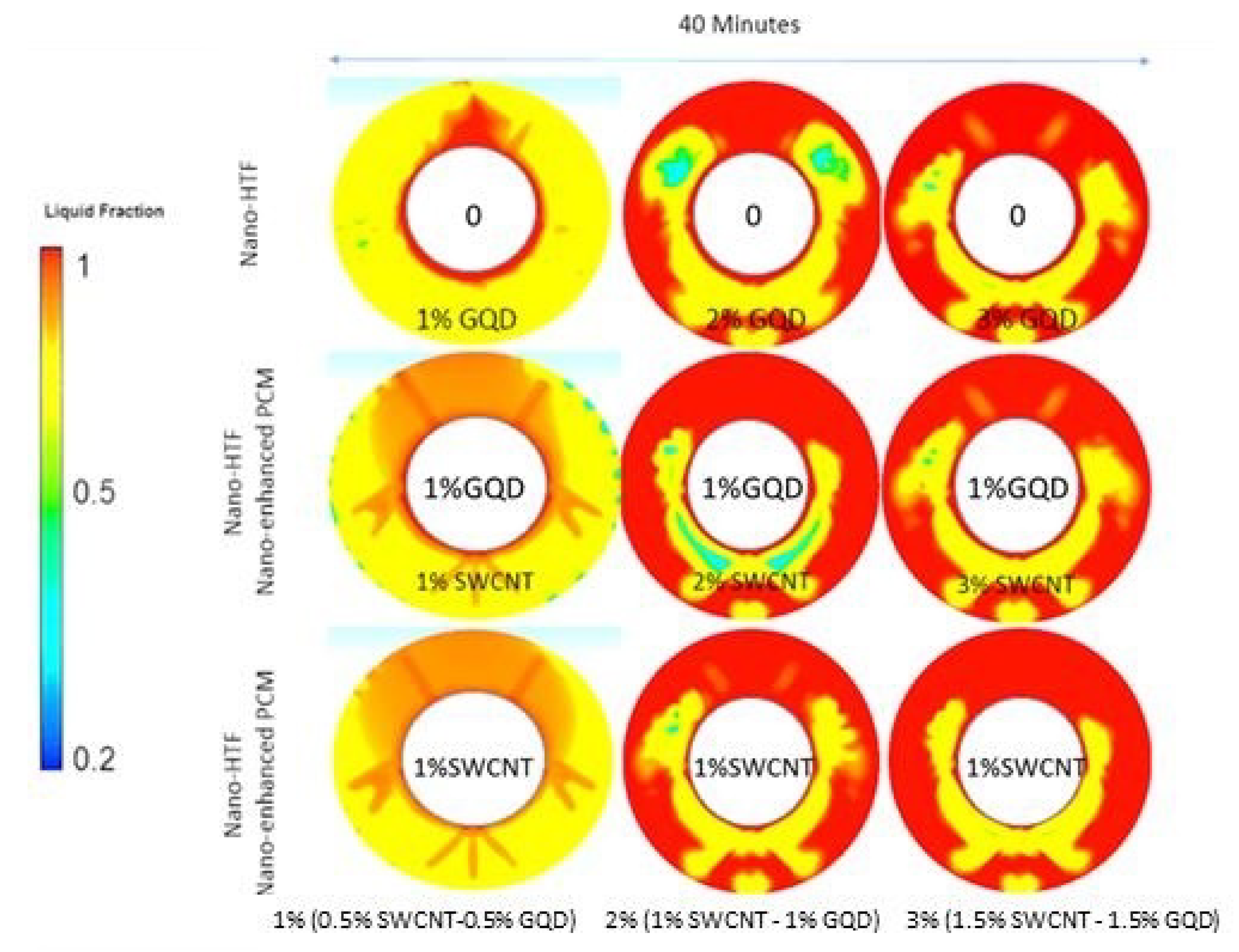
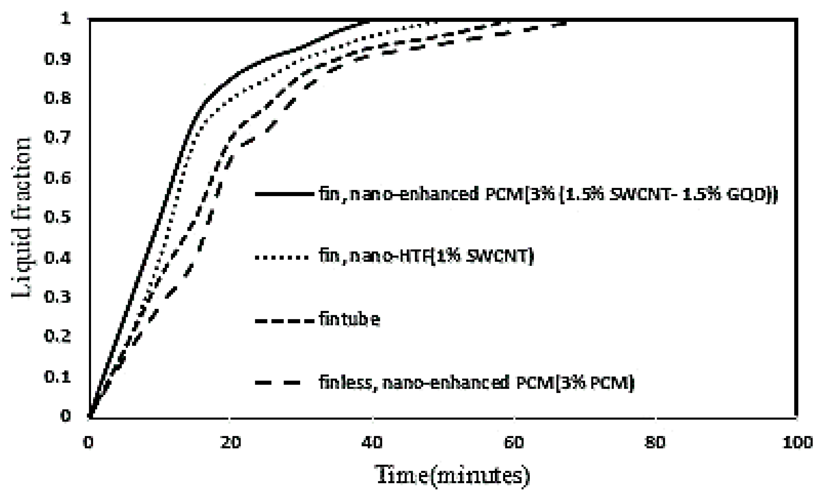
3.3. Effect of Fin Tubes and Nanoparticles (Nano-HTF and Nano-Enhanced PCM) on the PCM Melting Process

A comparison between the two types of using nanoparticles on the PCM melting process under different conditions is presented In Figure 6. It is indicated in Figure 6 that with increasing the percentage of nanoparticles in the nano-enhanced PCM type, the melting of the PCM increased. Because the use of higher percentages of nanoparticles in the nano-Enhanced PCM state increases the total thermal conductivity of PCM, which ultimately accelerates the melting process of PCM at the beginning of the melting process, which is effectively dependent on thermal conductivity. Increasing the mass fraction of nanoparticles in nano-HTF model has a far milder impact on the melting process than in another structural type, and the best possible case is to use a mass fraction of 1% of SWCNT in nano-HTF type, so that in this, the conditions create a balance between the effects of natural convection and thermal conductivity in HTF. While the increase of nanoparticles increases the density and gravity gradient and decreases the buoyancy force and natural convection [42,43]. The fin structure generally accelerates the melting of the PCM because the heat transfer surfaces increased, but with more time from the process and the appearance of a mushy state in the PCM, this fining compound prevents the ascent of thermal vortices due to natural convection. It has been so that the melting process of PCM was slowed down. It should also be noted that with this structure, the PCM melting time is reduced by 20 min compared to the normal state. The best case for PCM melting was to use 3% (1.5% SWCNT-1.5% GQD). Because in addition to increasing the total thermal conductivity of the PCM, due to the lower density of GQD than SWCNT, the desired density value was reduced and the buoyancy force and natural convection increased, which shortened the melting time.
Figure 7 shows the average PCM temperature in different states of the nanoparticle composition. As can be seen from Figure 7, the lower half of the heat exchanger conducts temperature changes, mostly by conduction heat transfer and the upper half by natural convection. In general, the use of nanoparticles and fin has played a complementary and very good role on the process of HTF temperature progress in PCM, so that nanoparticles and fin have a positive effect on the heat transfer rate of the heat exchanger. However, natural convection after the formation of a mushy state in PCM and a decrease in density and an increase in buoyancy force has played a complementary role in the process of melting the phase changing materials [16,42].

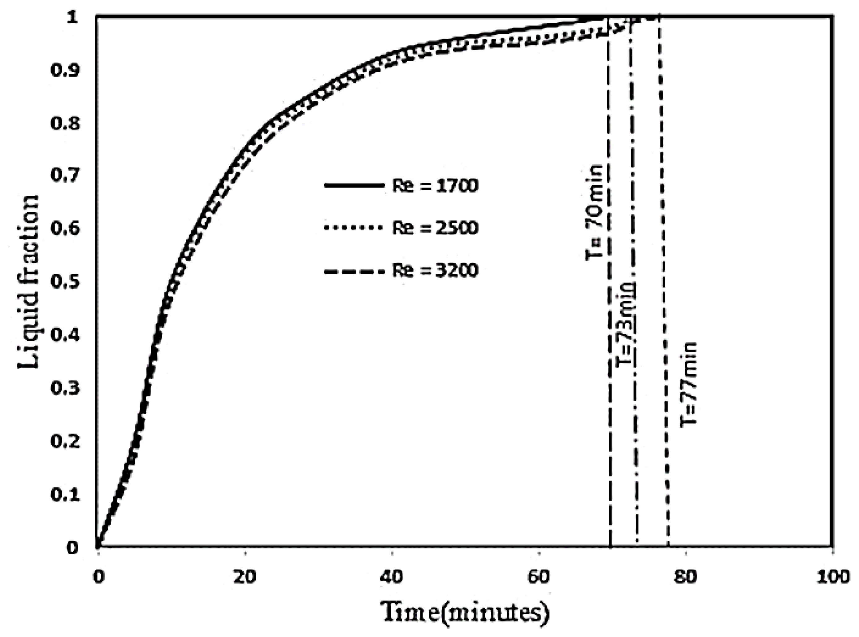
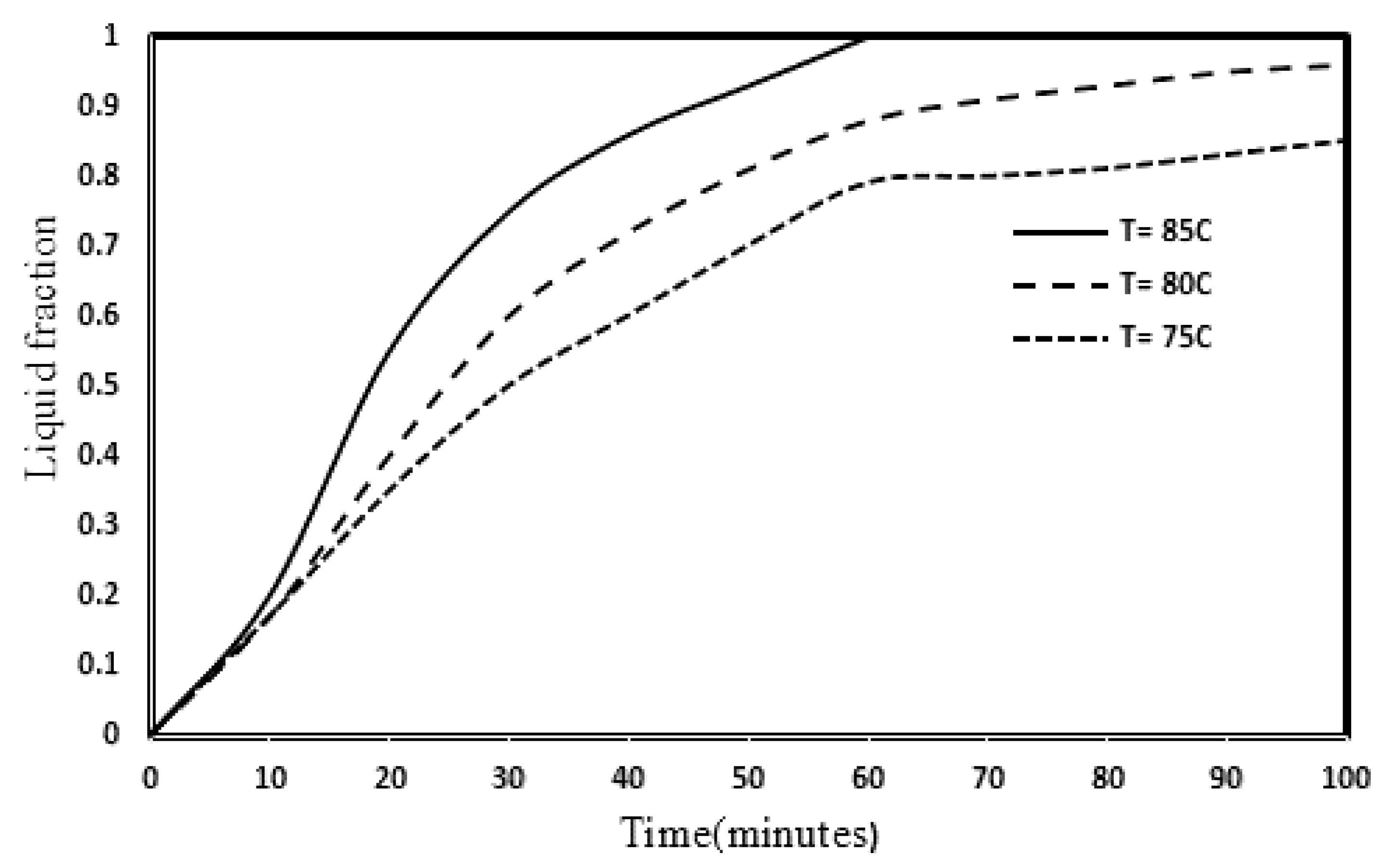
3.4. Influence of Inlet Temperature and Reynolds Numbers on the PCM Melting Process

The effects of three Reynolds numbers 1700, 2500 and 3200, as well as three inlet temperatures of HTF 75, 80 and 85 on the PCM melting process, are disclosed in Figure 8. It is clearly observed that, in Figure 8, the PCM melting has not changed significantly and even decreased with increasing Reynolds number, because with increasing Reynolds number in the range of laminar and transient flow, the residence time of the fluid in the pipe has decreased, and as a result, the duration HTF and PCM heat exchange decreased. Moreover, with increasing Reynolds number from 1700 to 2500, and from 2500 to 3200, entering the transient zone, the thickness of the HTF boundary layer decreased and more heat transfer was transferred from HTF to PCM, but with decreasing fluid retention time. The overall PCM melting rate decreased by 2% and 4%, respectively [44,45]. Furthermore, the results of this study are consistent with the results of Pahamli et al. [24], so that increasing the Reynolds number and inlet velocity increases the rate of heat transfer within the pipe, but does not have a significant effect on the overall heat transfer coefficient. In fact, increasing the Reynolds number increases the velocity of the fluid in the tube, which reduces the heat exchange time of the fluid inside the tube and the PCM material. On the other hand, increasing the Reynolds number reduces the thickness of the boundary layer on the pipe side and thus accelerates the convection heat transfer process. These two phenomena have neutralized each other, so there is not much impact on the melting process of PCM in this regime.
Figure 9 also shows the effect of three different HTF inlet temperatures on the PCM liquid fraction. The results show that by increasing the inlet temperature of HTF, PCM melts in less time, because more heat flux is transferred from the heat source (HTF) to PCM and more vortices due to natural convection are formed. They climb up. It should also be noted that the slope of the graph curve is high at 50% of the start of the process and decreases as the graph slope continues. Because initially due to the high temperature gradient of PCM and HTF and the presence of more natural convection vortices, the melting rate of PCM is higher, while reaching the end points of the melting process and reducing the temperature gradient and reducing the density, the effect of natural convection decreased. With increasing temperature from 75 to 80 and from 80 to 85, the melting rate of PCM increased by 21% and 23%, respectively. The results of this study are compared with the results of research by Pahamli et al. The results show that increasing the fluid inlet temperature from 75 °C to 80 °C has increased the melting rate of PCM by 21%, while in Pahamli et al.’s research, increasing the inlet fluid temperature by about 5 °C has improved the PCM melting rate by 16%.In fact, the graph below shows that increasing the temperature of the inlet fluid brings it closer to the full melting temperature of PCM, which also reduces the melting time of PCM. It should also be noted that at temperatures between the melting and freezing temperatures of PCM, the PCM material becomes a paste, which with increasing temperature of the inlet fluid, the time it takes for the paste to become an absolute liquid decreases.

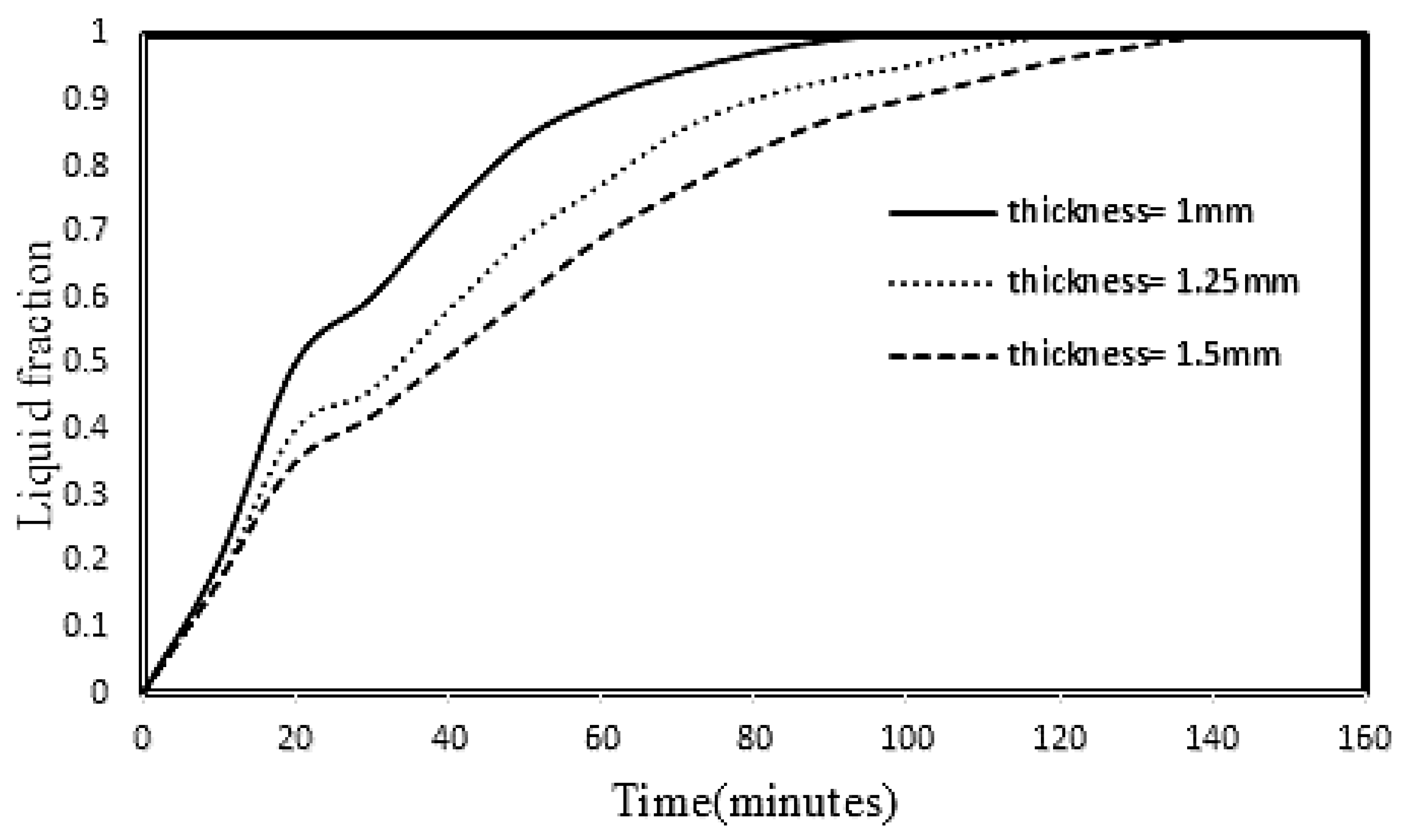
3.5. Effect of HTF Pipe and Fin Thickness on PCM Melting

Figure 10 discloses the effects of the thickness of the tube and the fin on the outside of the HTF in three states of 1, 1.25 and 1.5 mm at the inlet fluid temperature of 80 °C. As can be seen from the figure, a thickness of 1 mm shows the best performance of the PCM melting rate. Because less thickness of HTF pipe decreases the resistance of passing heat flux from the central part around the pipe. Furthermore, reducing the thickness of the pipe and fin causes faster heat transfer to the upper layers and vortices due to natural convection to occur more quickly, which reduces the melting process time. Furthermore, the thickness of 1 mm, compared to the thicknesses of 1.25 and 1.5 mm, improved the melting rate of PCM by 18% and 31%, respectively. On the other hand, the lower thickness of the fin prevents the high temperature gradient between the root points of the fin and the head of the fin, which causes faster heat flux transfer around the fin. The results of this factor show that the effect of reducing the thickness of the fin and pipe can reduce the cost of design and construction in addition to improving heat transfer, which has not been mentioned in other research.

3.6. Influence of Fin Tube, Nanoparticle Parameters on Melting Process of PCM

The effects of the best combination of nanoparticles with fin and non-fin heat exchanger on melting process of PCM are shown in Figure 11. As can be seen from Figure 11, the best combination is selected to be nano-enhanced PCM (3% (1.5% SWCNT-1.5% GQD)) and 1% SWCNT (Nano-HTF), because the use of this combination, in addition to increasing the conduction heat transfer by the nanoparticles in the HTF, increased the thermal conductivity of PCM and improved the PCM melting rate by about 40%, while the combination of nano-PCM alone has improved this process by a maximum of 25% [26,27,28]. Furthermore, the presence of nanoparticles and fines slightly reduces natural convection, but its positive effects on the PCM melting process are greater. The nano-HTF (1% SWCNT) state has less effect than the nano-enhanced PCM state, because the presence of nanoparticles in HTF is not able to increase the low thermal conductivity in PCM and only improves the thermal conductivity of HTF. It should be noted that increasing the mass fraction of nanoparticles in HTF increases the density and decreases the buoyancy force, thereby reducing the vortices caused by thermal convection within the HTF, which increases the melting time of PCM. The simultaneous use of nano-enhanced PCM and nano-HTF state compared to the other three states has improved the melting rate of PCM by 39%. In fact, the graph below shows that the combination of nanoparticles with PCM is more effective than the combination of nanoparticles with energy-carrying fluid, because this combination, in addition to improving the conduction heat transfer coefficient of PCM material, accelerates the convection heat transfer process, because with improved conduction heat transfer, the heat flux inside the tube rises faster to the higher layers. The effect of the fin blade is also evident, because it increases the surface of heat transfer, but the number and thickness of the fin blade must be selected so that the rise in heat flux due to convection is not reduced.
Figure 12 shows a comparison between different parameters that improve the PCM melting rate. As can be seen, the simultaneous use of dispersed nanoparticles in both HTF and PCM shows the best PCM melting state and the shortest melting time. Another parameter that can have a significant effect on reducing or increasing this process is changes in the thickness of the fin and the HTF tube. However, the two factors of Reynolds number change in the desired range, as well as changes in inlet flow temperature, are of less importance and impact.

4. Conclusions

In this work, the melting process of PCM (RT82) using three methods of combination of two nanoparticles SWCNT and GQD in mass fractions of 1, 2, 3 and 5% in HTF (nano-HTF) and PCM (nano-enhanced PCM) and fin and tube thickness as two new factors of melting process of PCM in series double tube heat exchanger with shell and tube heat exchanger was evaluated numerically. The following results are obtained:
-
At first, the melting process of PCM heat conduction mechanism was recognized as the dominant phenomenon, but in the continuation of the melting process and with the appearance of a mushy state in PCM, the heat convection mechanism was identified as the superior mechanism.
-
With the increase of HTF inlet temperature, the melting rate of PCM increased, so that with increasing temperature from 75 to 80 and from 80 to 85, the melting rate of PCM increased by 21% and 23%, respectively.
-
Increasing the Reynolds number in the laminar and transient flow range has not had a significant effect on the melting rate of PCM, because with increasing the Reynolds number from 1700 to 2500 and from 2500 to 3200 due to reducing the fluid retention time, PCM melting rate decreased by 2 and 4%, respectively.
-
The PCM melting process was improved by reducing the thickness of the HTF tube and the thickness of the fin, because the thermal resistance caused by the wall of the HTF tube was reduced, so that by increasing the thickness of the tube and the fan from 1 mm to 1.25 and 1.5 mm, the rate PCM melting decreased by 18% and 31%, respectively.
-
The best melting rate of PCM has been obtained by using finned tubes and a simultaneous combination of nano-enhanced PCM (3% (1.5% SWCNT-1.5% GQD)) and 1% SWCNT (nano-HTF). This is because both the heat transfer surfaces and the thermal conductivity of the PCM and HTF were increased, so that it improved the melting rate of the PCM by 39% compared to the conventional model in double tube heat exchangers.

Author Contributions

Conceptualization, A.M. and M.H.R.; methodology, M.H.R.; software, M.H.R.; validation, G.N., M.H.R. and W.-M.Y.; formal analysis, M.H.R.; investigation, M.H.R.; resources, A.M.; data curation, G.N.; writing—original draft preparation, M.H.R.; writing—review and editing, A.M.; visualization, W.-M.Y.; supervision, A.M.; project administration, A.M. All authors have read and agreed to the published version of the manuscript.

Funding

This research received no external funding.

Institutional Review Board Statement

This study did not involve humans or animals.

Informed Consent Statement

This study not involving humans.

Acknowledgments

The authors would like to acknowledge the Sari Agricultural Sciences and Natural Resources University in Iran for supporting the present research.

Conflicts of Interest

The authors declare no conflict of interest.

Nomenclatures

CPSpecific heat capacity (J/kg K)
ggravity (m/s2)
hsensible enthalpy (J/kg)
Llatent heat (J/kg)
Kthermal conductivity (W/m K)
Htotal enthalpy (J)
Ttemperature (K)
Ssource term
m ˙ mass flow rate (kg/s)
Vvelocity (m/s)
riinner radius (m)
roouter radius (m)
Tssolidus temperature (K)
Tlliquidus temperature (K)
HTFheat transfer fluid
PCMphase change material
Greek symbols
μdynamic viscosity (Pa s)
ρdensity (kg/m3)
φmass fraction
εsmall parameter for avoiding division by zero
βthermal expansion coefficient (1/K)
λliquid fraction
Γlatent heat of fusion (kJ/kg K)
Subscripts
refreference
wwall
bfbase fluid
nfnanofluid
npnanoparticle

References

  1. Rostami, S.; Afrand, M.; Shahsavar, A.; Sheikholeslami, M.; Kalbasi, R.; Aghakhani, S.; Shadloo, M.S.; Oztop, H.F. A review of melting and freezing processes of PCM/nano-PCM and their application in energy storage. Energy 2020, 211, 118698. [Google Scholar] [CrossRef]
  2. Huang, X.; Zhu, C.; Lin, Y.; Fang, G. Thermal properties and applications of microencapsulated PCM for thermal energy storage: A review. Appl. Therm. Eng. 2019, 147, 841–855. [Google Scholar] [CrossRef]
  3. Kalapala, L.; Devanuri, J.K. Influence of operational and design parameters on the performance of a PCM based heat exchanger for thermal energy storage—A review. J. Energy Storage 2018, 20, 497–519. [Google Scholar] [CrossRef]
  4. Medrano, M.; Yilmaz, M.O.; Nogués, M.; Martorell, I.; Roca, J.; Cabeza, L.F. Experimental evaluation of commercial heat exchangers for use as PCM thermal storage systems. Appl. Energy 2009, 86, 2047–2055. [Google Scholar] [CrossRef]
  5. Anish, R.; Mariappan, V.; Joybari, M.M. Experimental investigation on the melting and solidification behavior of erythritol in a horizontal shell and multi-finned tube latent heat storage unit. Appl. Therm. Eng. 2019, 161, 161,114194. [Google Scholar] [CrossRef]
  6. Trp, A. An experimental and numerical investigation of heat transfer during technical grade paraffin melting and solidification in a shell-and-tube latent thermal energy storage unit. Sol. Energy 2005, 79, 648–660. [Google Scholar] [CrossRef]
  7. Alizadeh, M.; Hosseinzadeh, K.; Shahavi, M.H.; Ganji, D.D. Solidification acceleration in a triplex-tube latent heat thermal energy storage system using V-shaped fin and nano-enhanced phase change material. Appl. Therm. Eng. 2019, 163, 114436. [Google Scholar] [CrossRef]
  8. Ettouney, H.M.; Alatiqi, I.; Al-Sahali, A.; Al-Ali, S.A. Heat transfer enhancement by metal screens and metal spheres in phase change energy storage systems. Renew. Energy 2004, 29, 841–860. [Google Scholar] [CrossRef]
  9. Rahimi, M.; Ranjbar, A.A.; Ganji, D.D.G.-D.; Sedighi, K.; Hosseini, S.M.J.; Bahrampoury, R. Analysis of geometrical and operational parameters of PCM in a fin and tube heat exchanger. Int. Commun. Heat Mass Transf. 2014, 53, 109–115. [Google Scholar] [CrossRef]
  10. Lin, W.; Ling, Z.; Fang, X.; Zhang, Z. Experimental and numerical research on thermal performance of a novel thermal energy storage unit with phase change material. Appl. Therm. Eng. 2021, 186, 116493. [Google Scholar] [CrossRef]
  11. Regin, A.F.; Solanki, S.C.; Saini, J.S. Latent heat thermal energy storage using cylindrical capsule: Numerical and experimental investigations. Renew. Energy 2006, 31, 2025–2041. [Google Scholar] [CrossRef]
  12. Kibria, M.A.; Anisur, M.R.; Mahfuz, M.H.; Saidur, R.; Metselaar, I.H.S.C. Numerical and experimental investigation of heat transfer in a shell and tube thermal energy storage system. Int. Commun. Heat Mass Transf. 2014, 53, 71–78. [Google Scholar] [CrossRef]
  13. Ismail, K.A.R.; Lino, F.A.M.; da Silva, R.C.R.; de Jesus, A.B.; Paixão, L.C. Experimentally validated two dimensional numerical model for the solidification of PCM along a horizontal long tube. Int. J. Therm. Sci. 2014, 75, 184–193. [Google Scholar] [CrossRef]
  14. Başal, B.; Ünal, A. Numerical evaluation of a triple concentric-tube latent heat thermal energy storage. Sol. Energy 2013, 92, 196–205. [Google Scholar] [CrossRef]
  15. Hosseini, S.M.J.; Rahimi, M.; Bahrampoury, R. Experimental and computational evolution of a shell and tube heat exchanger as a PCM thermal storage system. Int. Commun. Heat Mass Transf. 2014, 50, 128–136. [Google Scholar] [CrossRef]
  16. Hosseini, S.M.J.; Ranjbar, A.A.; Sedighi, K.; Rahimi, M. A combined experimental and computational study on the melting behavior of a medium temperature phase change storage material inside shell and tube heat exchanger. Int. Commun. Heat Mass Transf. 2012, 39, 1416–1424. [Google Scholar] [CrossRef]
  17. Al-Abidi, A.A.; Mat, S.; Sopian, K.; Sulaiman, M.Y.; Mohammad, A.T. Experimental study of melting and solidification of PCM in a triplex tube heat exchanger with fins. Energy Build. 2014, 68, 33–41. [Google Scholar] [CrossRef]
  18. Esapour, M.; Hosseini, S.M.J.; Ranjbar, A.A.; Pahamli, Y.; Bahrampoury, R. Phase change in multi-tube heat exchangers. Renew. Energy 2016, 85, 1017–1025. [Google Scholar] [CrossRef]
  19. Esapour, M.; Hosseini, M.J.; Ranjbar, A.A.; Bahrampoury, R. Numerical study on geometrical specifications and operational parameters of multi-tube heat storage systems. Appl. Therm. Eng. 2016, 109, 351–363. [Google Scholar] [CrossRef]
  20. Kousha, N.; Hosseini, S.M.J.; Aligoodarz, M.R.; Pakrouh, R.; Bahrampoury, R. Effect of inclination angle on the performance of a shell and tube heat storage unit—An experimental study. Appl. Therm. Eng. 2017, 112, 1497–1509. [Google Scholar] [CrossRef]
  21. Mat, S.; Al-Abidi, A.A.; Sopian, K.; Sulaiman, M.Y.; Mohammad, A.T. Enhance heat transfer for PCM melting in triplex tube with internal–external fins. Energy Convers. Manag. 2013, 74, 223–236. [Google Scholar] [CrossRef]
  22. Adine, H.A.; Qarnia, H.E. Numerical analysis of the thermal behavior of a shell and tube heat storage unit using phase change materials. Appl. Math. Model. 2009, 33, 2132–2144. [Google Scholar] [CrossRef]
  23. Pakrouh, R.; Hosseini, S.M.J.; Ranjbar, A.A.; Bahrampoury, R. A numerical method for PCM-based pin fin heat sinks optimization. Energy Convers. Manag. 2015, 103, 542–552. [Google Scholar] [CrossRef]
  24. Pahamli, Y.; Hosseini, M.J.; Ranjbar, A.A.; Bahrampoury, R. Analysis of the effect of eccentricity and operational parameters in PCM-filled single-pass shell and tube heat exchangers. Renew. Energy 2016, 97, 344–357. [Google Scholar] [CrossRef]
  25. Kok, B. Examining effects of special heat transfer fins designed for the melting process of PCM and Nano-PCM. Appl. Therm. Eng. 2020, 170, 114989. [Google Scholar] [CrossRef]
  26. Sun, X.; Liu, L.; Mo, Y.; Li, J.; Li, C. Enhanced thermal energy storage of a paraffin-based phase change material (PCM) using nano carbons. Appl. Therm. Eng. 2020, 181, 115992. [Google Scholar] [CrossRef]
  27. Ebadi, S.; Tasnim, S.H.; Aliabadi, A.A.; Mahmud, S. Geometry and nanoparticle loading effects on the bio-based nano-PCM filled cylindrical thermal energy storage system. Appl. Therm. Eng. 2018, 141, 724–740. [Google Scholar] [CrossRef]
  28. Li, Z.; Shahsavar, A.; Al-Rashed, A.A.; Talebizadehsardari, P. Effect of porous medium and nanoparticles presences in a counter-current triple-tube composite porous/nano-PCM system. Appl. Therm. Eng. 2020, 167, 114777. [Google Scholar] [CrossRef]
  29. Kristiawan, B.; Santoso, B.; Wijayanta, A.T.; Aziz, M.; Miyazaki, T. Heat Transfer Enhancement of TiO2/Water Nanofluid at Laminar and Turbulent Flows: A Numerical Approach for Evaluating the Effect of Nanoparticle Loadings. Energies 2018, 11, 1584. [Google Scholar] [CrossRef] [Green Version]
  30. Kristiawan, B.; Wijayanta, A.T.; Enoki, K.; Miyazaki, T.; Aziz, M. Heat transfer enhancement of TiO2/water nanofluids flowing inside a square minichannel with a microfin structure: A numerical investigation. Energies 2019, 12, 3041. [Google Scholar] [CrossRef] [Green Version]
  31. Kristiawan, B.; Rifa’I, A.I.; Enoki, K.; Wijayanta, A.T.; Miyazaki, T. Enhancing the thermal performance of TiO2/water nanofluids flowing in a helical microfin tube. Powder Technol. 2020, 376, 254–262. [Google Scholar] [CrossRef]
  32. Nitsas, M.T.; Koronaki, I.P. Thermal analysis of pure and nanoparticle-enhanced PCM—Application in concentric tube heat exchanger. Energies 2020, 13, 3841. [Google Scholar] [CrossRef]
  33. Fong, M.; Kurnia, J.; Sasmito, A.P. Application of phase change material-based thermal capacitor in double tube heat exchanger—A numerical investigation. Energies 2020, 13, 4327. [Google Scholar] [CrossRef]
  34. ANSYS. Fluent Theory Guide; Ansys. Inc.: Canonsburg, PA, USA, 2012. [Google Scholar]
  35. Al-Abidi, A.A.; Bin Mat, S.; Sopian, K.; Sulaiman, M.Y.; Mohammad, A.T. CFD applications for latent heat thermal energy storage: A review. Renew. Sustain. Energy Rev. 2013, 20, 353–363. [Google Scholar] [CrossRef]
  36. Mahdi, J.M.; Lohrasbi, S.; Ganji, D.D.; Nsofor, E. Accelerated melting of PCM in energy storage systems via novel configuration of fins in the triplex-tube heat exchanger. Int. J. Heat Mass Transf. 2018, 124, 663–676. [Google Scholar] [CrossRef]
  37. Mahdi, J.M.; Nsofor, N.C. Solidification enhancement of PCM in a triplex-tube thermal energy storage system with nanoparticles and fins. Appl. Energy 2018, 211, 975–986. [Google Scholar] [CrossRef]
  38. Vajjha, R.S.; Das, D.K. Experimental determination of thermal conductivity of three nanofluids and development of new correlations. Int. J. Heat Mass Transf. 2009, 52, 4675–4682. [Google Scholar] [CrossRef]
  39. Vajjha, R.S.; Das, D.K.; Namburu, P.K. Numerical study of fluid dynamic and heat transfer performance of Al2O3 and CuO nanofluids in the flat tubes of a radiator. Int. J. Heat Fluid Flow 2010, 31, 613–621. [Google Scholar] [CrossRef]
  40. Patankar, S.V. Numerical Heat Transfer and Fluid Flow; CRC Press: Boca Raton, FL, USA, 1980; ISBN 9781315275130. [Google Scholar]
  41. Leonard, B. A stable and accurate convective modelling procedure based on quadratic upstream interpolation. Comput. Methods Appl. Mech. Eng. 1979, 19, 59–98. [Google Scholar] [CrossRef]
  42. Rostami, M.H.; Najafi, G.; Motevalli, A.; Sidik, N.A.C.; Harun, M.A. Evaluation and improvement of thermal energy of heat exchangers with SWCNT, GQD nanoparticles and PCM (RT82). J. Adv. Res. Fluid Mech. Therm. Sci. 2020, 79, 153–168. [Google Scholar] [CrossRef]
  43. Mahdi, J.M.; Lohrasbi, S.; Ganji, D.D.; Nsofor, E.C. Simultaneous energy storage and recovery in the triplex-tube heat exchanger with PCM, copper fins and Al2O3 nanoparticles. Energy Convers. Manag. 2019, 180, 949–961. [Google Scholar] [CrossRef]
  44. Rostami, M.H.; Ghobadian, B.; Najafi, G.; Motevali, A.; Sidik, N.A.C. CFD study based on effect of employing the single-walled carbon nanotube (SWCNT) and graphene quantum dots (GQD) nanoparticles and a particular fin configuration on the thermal performance in the shell and tube heat exchanger. CFD Lett. 2020, 12, 37–60. [Google Scholar] [CrossRef]
  45. Rostami, M.H.; Najafi, G.; Ghobadin, B.; Motevali, A. Thermal performance investigation of SWCNT and graphene quantum dots nanofluids in a shell and tube heat exchanger by using fin blade tubes. Heat Transf. 2020, 49, 4783–4800. [Google Scholar] [CrossRef]
Figure 1. Schematic representation of double tube heat exchanger and its configuration.
Sustainability 13 10675 g001
Figure 2. Initial and boundary conditions of heat exchanger under different conditions.
Sustainability 13 10675 g002
Figure 3. Comparison of the present predictions with data reported: (a) Comparison of PCM melting temperature versus melting time by Hosseini et al. [16] and (b) Comparison of different mass fractions of nanoparticles on the melting process by Rostami et al. [43].
Sustainability 13 10675 g003aSustainability 13 10675 g003b
Figure 4. Comparison of different mass fractions of nanoparticles on the melting process of PCM (nano-enhanced PCM) in double tube heat exchanger at 80 °C.
Sustainability 13 10675 g004
Figure 5. Comparison of different mass fractions of nanoparticles (nano-HTF) on the melting process at 80 °C.
Sustainability 13 10675 g005
Figure 6. Comparison between the simultaneous effect of Nano-Enhanced PCM and Nano-HTF on the melting process at 80 °C.
Sustainability 13 10675 g006
Figure 7. Comparison between different modes of using nanoparticles on the PCM temperature distributions.
Sustainability 13 10675 g007
Figure 8. The effect of Reynolds numbers on PCM melting at 80 °C.
Sustainability 13 10675 g008
Figure 9. The effects of different inlet temperatures on PCM melting at Reynolds number of 1700.
Sustainability 13 10675 g009
Figure 10. Comparison of three modes of HTF pipe and fin thickness on PCM melting.
Sustainability 13 10675 g010
Figure 11. Comparison of parameters of nanoparticles, fin tubes and finless tubes on PCM melting.
Sustainability 13 10675 g011
Figure 12. Comparison of parameters affecting PCM melting process.
Sustainability 13 10675 g012
Table 1. Thermophysical properties of RT82 as PCM, Copper fin, GQD and SWCNT nanoparticles.
PropertiesRT82Copper FinGQDSWCNT
ρ (kg/m3)77089204002600
CP (J/kgK)2000380643425
k (W/mK)0.240030006600
μ (Ns/m2)0.03499---
Γ (kJ/kg)176---
T s (K)350---
T l (K)358---
β (1/K)0.001---
Publisher’s Note: MDPI stays neutral with regard to jurisdictional claims in published maps and institutional affiliations.

