Article

A Stability Improvement Method of DC Microgrid System Using Passive Damping and Proportional-Resonance (PR) Control

1
Department of Electrical and Biomedical Engineering, Hanyang University, Seoul 04763, Korea
2
Department of Electrical Engineering, Jeju National University, Jeju 63243, Korea
*
Author to whom correspondence should be addressed.
Sustainability 2021, 13(17), 9542; https://doi.org/10.3390/su13179542
Submission received: 28 July 2021 / Revised: 20 August 2021 / Accepted: 21 August 2021 / Published: 25 August 2021

Abstract

:
Sustainable energy, such as sunlight and wind energy, that comes from sources that do not need to be replenished has become important. Accordingly, the importance of the design and stable management of DC microgrids is also increasing. From this point of view, this paper analyzes the interaction between source and load converters constituting the DC microgrid using the derived mathematical input and output impedances models. This paper proposes a stability improvement method using the analyzed result. The method focuses on the presence or absence of input and output impedance overlap using Middlebrook’s stability criteria. To verify validity of the proposed method, a case study with three damping methods is conducted: (1) RC parallel damping with PR controller, (2) RL parallel damping with PR controller, and (3) RL series damping with PR controller. Additionally, the frequency domain characteristics and the Nyquist stability are analyzed using MATLAB, and simulation verification is conducted using PSIM. Through the analysis and simulation results, we confirm that the stability of the DC microgrid can be improved by applying the proposed method. The passive damping method analyzed in this paper is applied to an installed power converter, where it is possible to ensure the stability of the DC microgrid.

1. Introduction

Electrical energy is an essential resource for beings. However, gas emissions from power generation using fossil fuels causes global warming and environmental pollution problems that cannot be overlooked any more. To resolve this problem, the literature research on the production of electric energy using renewable energy sources such as solar and wind power with microgrids is being actively conducted [1,2,3]. Since a microgrid independently produces and supplies electrical energy using distributed energy sources, many studies on the management of microgrids have been conducted from the perspective of securing stability or improving effectiveness [4,5,6,7].
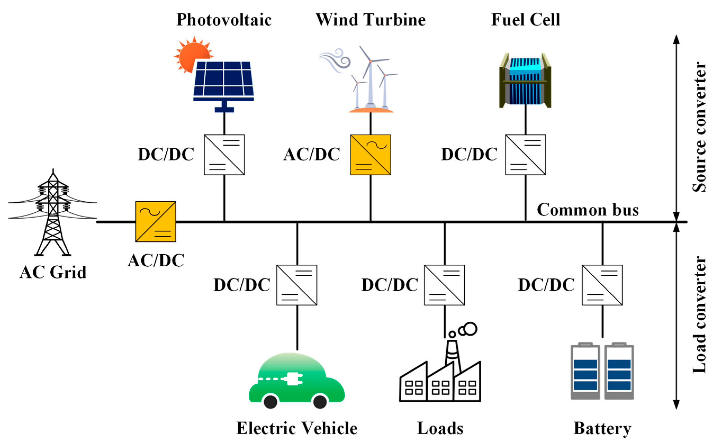
Microgrids can be classified into alternating current (AC) and direct current (DC) microgrids. DC microgrid systems can be designed with a simple power conversion step compared to AC microgrid systems. The simplified power conversion step operates with low power loss and is prone to control, as it does not require reactive power and frequency control [8,9]. In a DC microgrid system, as shown in Figure 1, several converters are connected into a common bus (CB). Each converter is individually designed to operate seamlessly. However, in a microgrid system in which several converters operate simultaneously, unexpected interactions between converters may occur, which adversely affect other converters connected to the common bus, resulting in instability of the entire system [10,11,12]. Therefore, there is a need for a method to prevent malfunctions between converters and improve the stability of the system.
Various methods such as Middlebrook’s stability criterion, Gain Margin Phase Margin (GMPM) stability criterion, the Opposing Argument Criterion (OAC), and Passivity-Based Stability Criterion (PBSC) have been proposed to determine stability of a microgrid system composed of several converters [13,14]. In these methods, the load converter is represented by the input impedance and the source converter is represented by the output impedance according to the direction of equalizing the converters constituting the system in the common bus. The stability of the system is determined using Middlebrook’s stability criterion among the various methods mentioned above. This method has the advantage of being able to intuitively determine the stability through the presence or absence of overlapping of input impedance and output impedance on the Bode plot.
Several studies have been conducted to solve the system stability problem caused by the unexpected impedance overlap between converters, and there are active and passive methods [15,16,17,18]. The active method secures stability by adding only a controller to the conventional circuit without any auxiliary circuits or device additions on power flow [15,16]. This method has the advantage of no power loss, and it can simply correct the damping effect. However, this method has disadvantages: as control complexity increases, and an additional sensing circuit is required. The passive method applies the damping effect to the conventional circuit by adding a passive element on the power flow [17,18]. Although this method has the disadvantage of causing some power loss, it has the advantages of simple implementation and no need for additional sensing circuits or control loops.
While the stability due to impedance overlap should be considered internally in the DC microgrid system, the stability problem that occurs in connection with the AC grid should be considered externally. As shown in Figure 1, when the DC microgrid system is connected to the AC grid, the stability of the system becomes unstable due to the voltage and current distortion caused by the harmonics generated in the AC grid. Therefore, it is necessary to consider not only the unexpected interaction (impedance overlap) between converters, but also the effect of harmonics generated in the AC grid.
To solve stability issues, the proportional-resonance (PR) control method that reduces the harmonics effect from the AC grid is applied. In addition, passive damping methods such as resistor and inductor (RL) series, resistor and inductor (RL) parallel, and resistor and capacitor (RC) parallel are applied to reduce the malfunctioning interaction between converters. As mentioned above, the passive damping method has a disadvantage of increased loss compared to the active damping method; however, it has low control complexity and is relatively simple to apply to a pre-installed DC microgrid power converter. From this point of view, we performed a stability analysis based on passive damping. Each method was comparatively analyzed through a case study, and eventually, a method for selecting an appropriate passive damping was constructed.
For effective understanding, this paper is organized as follows: In Section 2, the output impedance of the source converter and the input impedance of the load converter are derived through impedance modeling of the converters. Section 3 includes the stability analysis and determination process of the system through impedance modeling. Section 4 presents a case study applying passive damping and a PR controller to improve system stability. Section 5 presents the simulation verification by using a simulation tool (PowerSim: PSIM), and Section 6 describes the conclusions of this paper.

2. Impedance Modeling Using g-Parameter

A DC microgrid system consists of several converters, as shown in Figure 1. The converters constituting the system are designed to operate stably during independent operation. However, when a stably operating converter is operated in conjunction, the stability of the system may deteriorate due to the interaction between the converters. Therefore, it is necessary to analyze the cause of the stability issue of the system. In this paper, to analyze the stability, impedance modeling for the converter composing the system is conducted using 
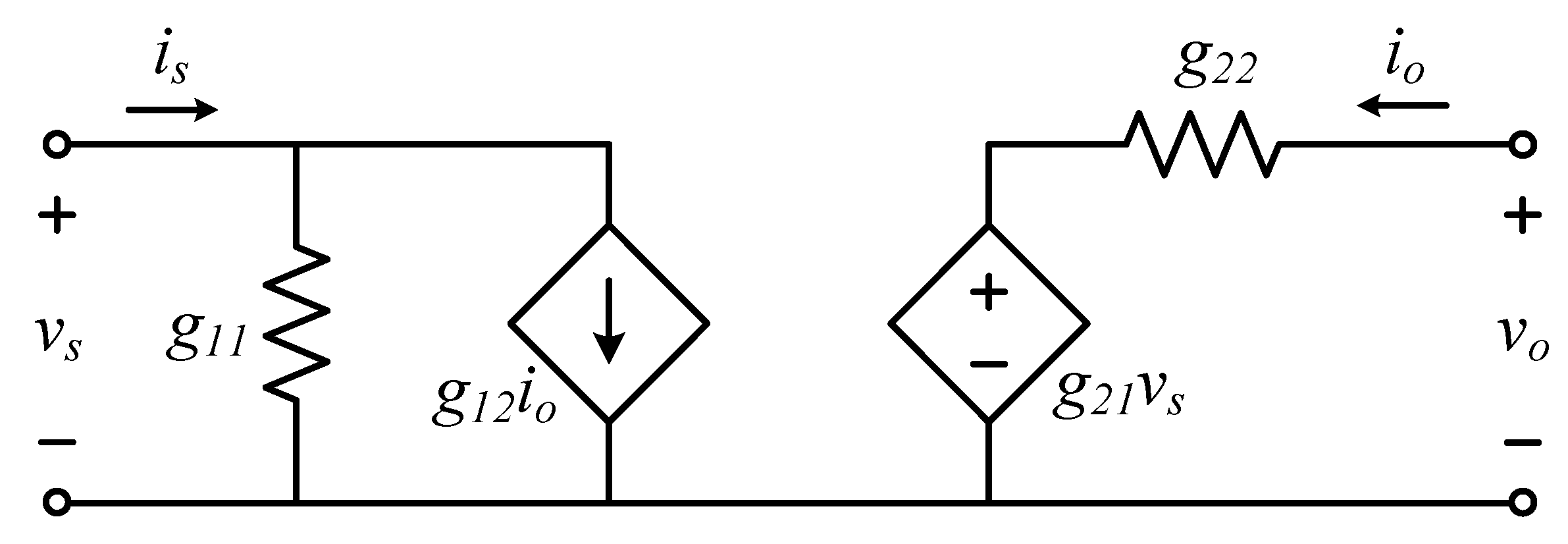
g parameters. Through impedance modeling using g parameters, it can be represented as an equivalent circuit for the converter, as shown in Figure 2, where g11 is the open circuit input admittance, g12 is the short circuit current transfer function, g21 is the open circuit voltage transfer function, and g22 is the short circuit output impedance [19]. The input and output transfer functions are obtained as shown in Equation (1).
v o v s = g 21 1 + g 22 L o a d
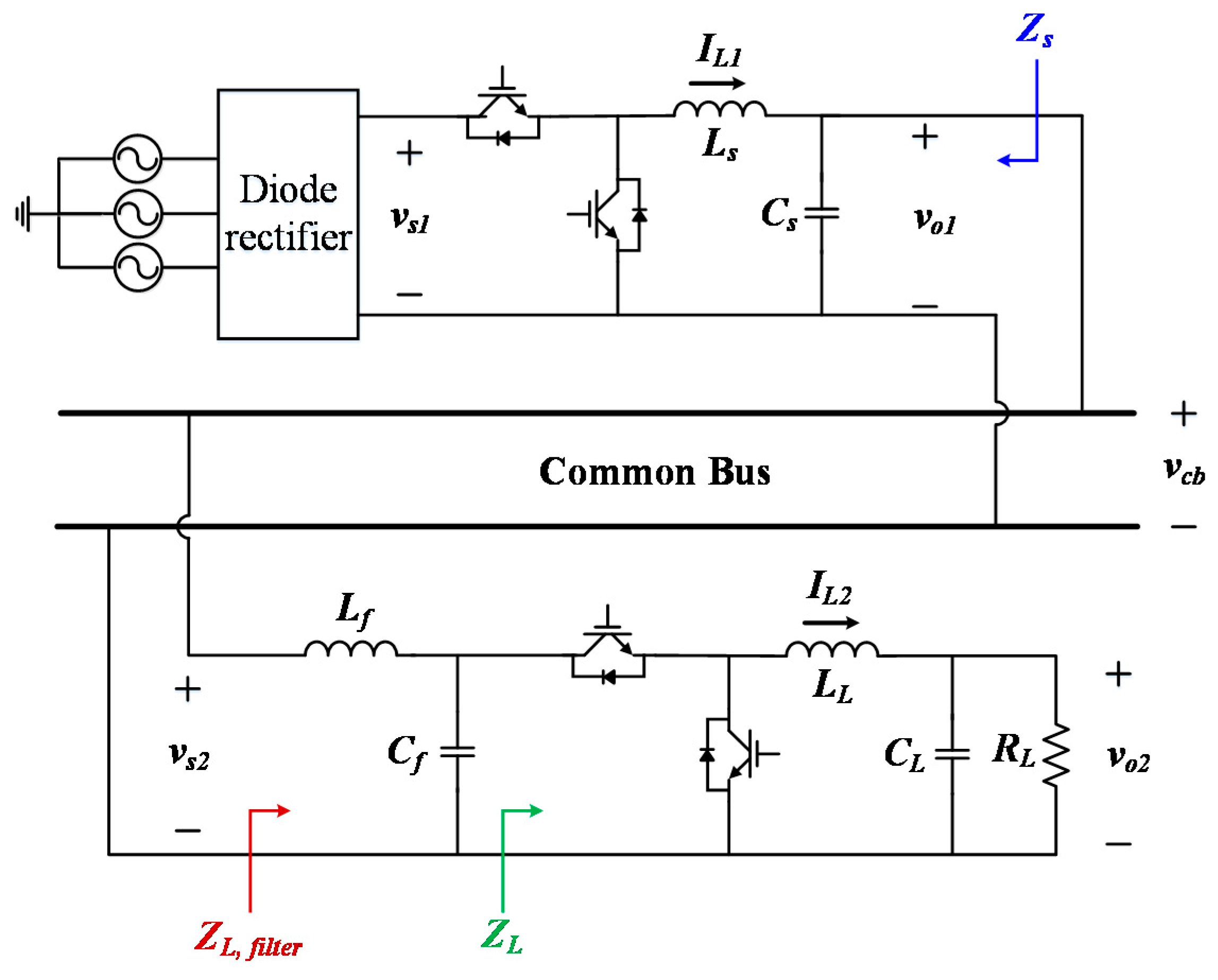
When the DC microgrid system is simplified to a source converter and a load converter and applied to a cascaded system, the input and output relationship is expressed as Equation (2), which is shown in Figure 3, where g 21 s is the open circuit transfer function of the source converter and g 21 L is the open circuit transfer function of the load converter, which do not affect the stability. The denominator composed of the input impedance and the output impedance contains the characteristic equation of the system. This term is defined as the minor loop gain, TMLG, which is used to analyze the stability of the system.
v o 2 v s 1 = g 21 s g 21 L 1 + Z s Z L _ f i l t e r = g 21 s g 21 L 1 + T M L G

2.1. Modeling of Converter Input Impedance

The input impedance to the converter is obtained from the common bus in the direction facing the input terminal of the load converter, and this is the same direction as ZL_filter in Figure 3 [20]. The input impedance including the controller is as shown in Equation (3), and Zx_filter and Zy_filter constituting the input impedance are as shown in Equations (4) and (5), where, ZLf and ZCf are the impedances of the inductor and capacitor constituting the input filter, respectively; and Zx and Zy are the values composing the input impedance of the load converter without the input filter.
Z L _ f i l t e r ( s ) = 1 Z x _ f i l t e r ( s ) T L 1 + T L + 1 Z y _ f i l t e r ( s ) 1 1 + T L
Z L ( s ) | d ^ ( s ) = 0 = Z x _ f i l t e r ( s ) = Z C f ( Z L f + Z x ) + Z L f Z x Z C f + Z x
Z L ( s ) | v ^ ( s ) = 0 = Z y _ f i l t e r ( s ) = Z C f ( Z L f + Z y ) + Z L f Z y Z C f + Z y
The loop gain TL is as shown in Equation (6), where Gid,L denotes the control to inductor current transfer function of the load converter [21].
T L = C L ( s ) G i d , L ( s ) G M
In this paper, the buck converter is used as the load converter, and the input impedance for the buck converter, including the input filter, is obtained by substituting Equations (7) and (8) into Equation (3).
Z x _ f i l t e r ( s ) = s L f + s L L ( 1 + s C L R L ) + R L s 2 C f L L ( 1 + s C L R L ) + s C f R L + D L 2 ( 1 + s C L R L )
Z y _ f i l t e r ( s ) = s L f + R L D L 2 + s C f R L

2.2. Modeling of Converter Output Impedance

The output impedance to the converter is obtained through the Thevenin equivalent circuit in the direction facing the output of the source converter from the common bus [22]. In this paper, the source converter is a buck converter, and the output impedance excluding the controller is
Z o ( s ) = v ^ o 1 ( s ) i ^ o 1 ( s ) | d ^ = 0 v ^ s 1 = 0 = s L s R s s 2 L s C s R s + s L s + R s
The output impedance includes the controller (Equation (10)), where Ls, Cs, and Rs represent the passive elements constituting the source converter. Ts represents the loop gain of the source converter (Equation (11)), where Gvd denotes control to output transfer function, Cs(s) is the controller of the source converter, and GM is the pulse width modulation gain.
Z o _ C L ( s ) = Z o ( s ) 1 + T s = s L s R s s 2 L s C s R s + s L s + R s 1 1 + T s
T s = C s ( s ) G v d , s ( s ) G M

2.3. Stability Analysis through Input and Output Impedance Modeling

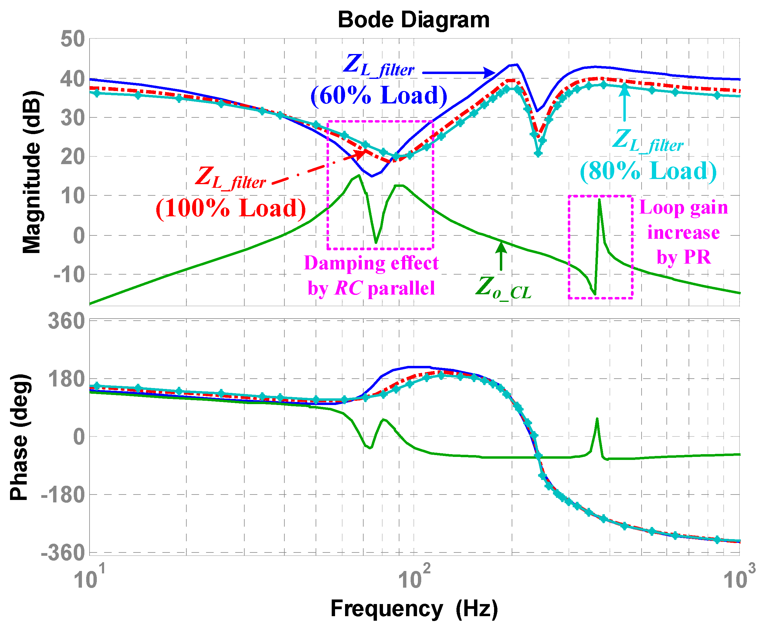
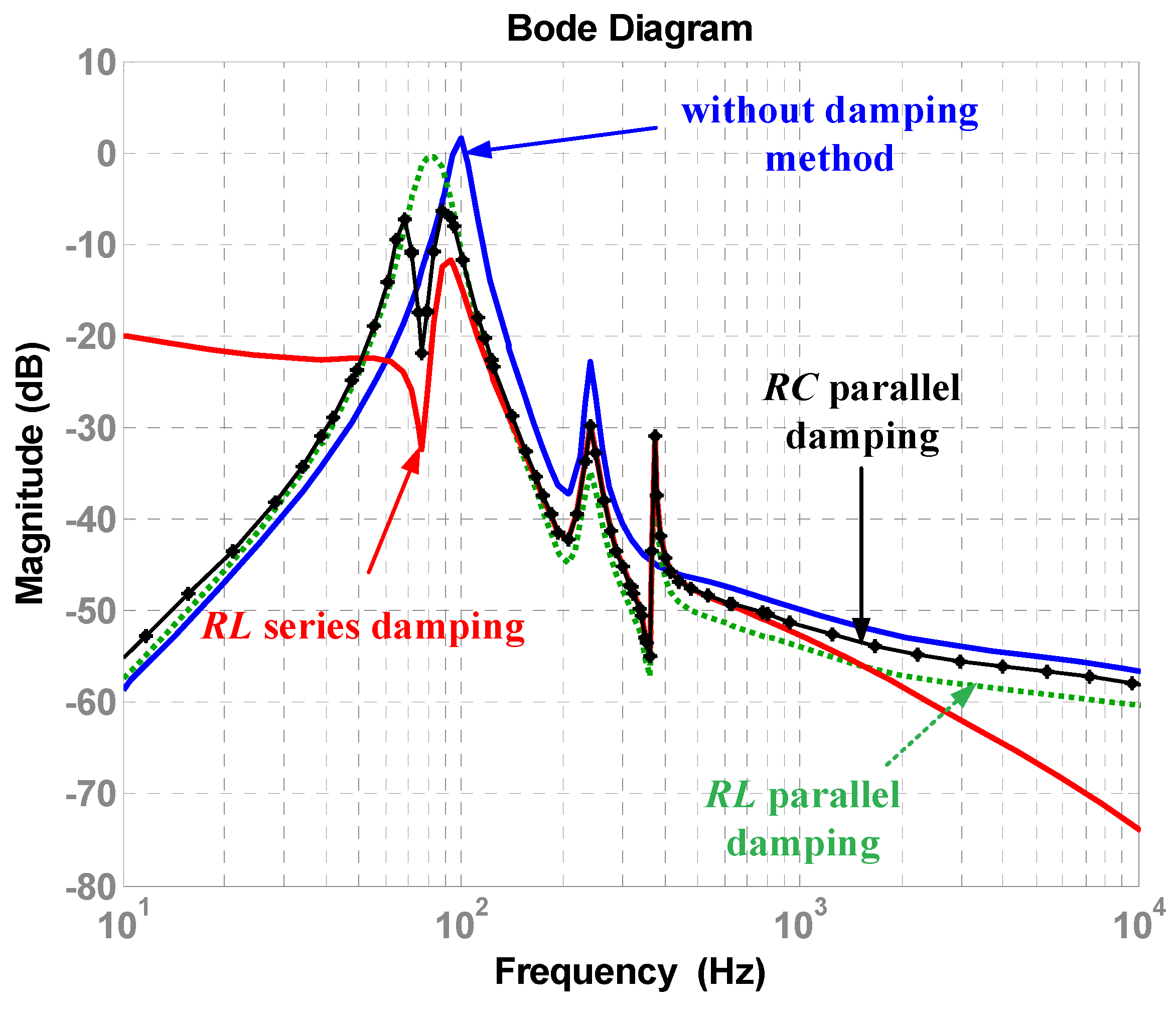
Figure 4 shows the results of stability analysis using input impedance and output impedance. As can be seen from the figure, input and output impedance overlap does not occur in at 60% load, which means the system is stable according to Middlebrook’s stability criterion in Equation (12) [23]. However, at a load of 80% or more, impedance overlap occurs, and the system becomes unstable. The impedance overlap is caused by the LC resonance of the converter, and an additional method for reducing it is required.
T M L G = Z o _ C L ( s ) Z L _ f i l t e r ( s ) 1 : stable , T M L G = Z o _ C L ( s ) Z L _ f i l t e r ( s ) 1 : unstable

3. Damping Method

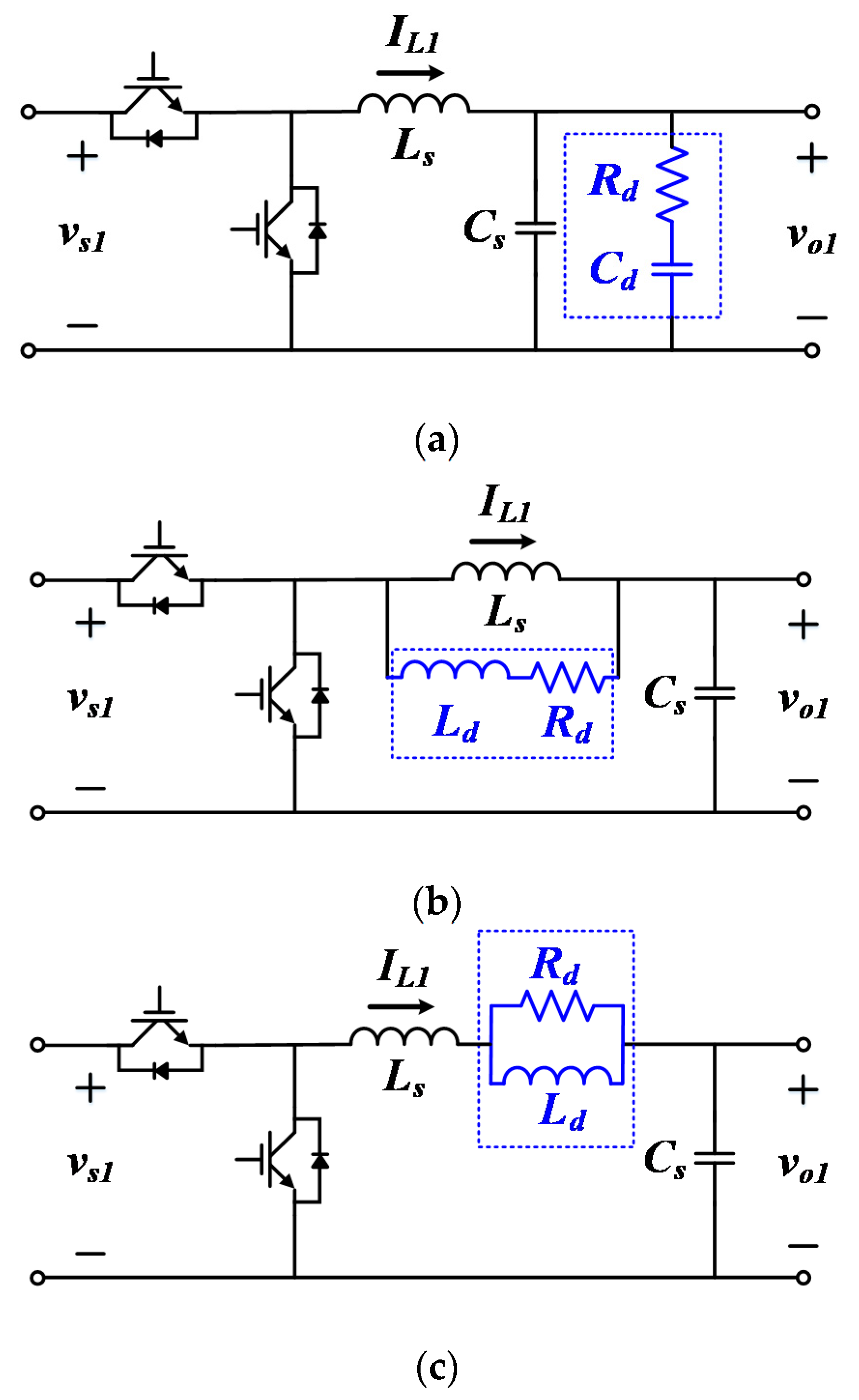
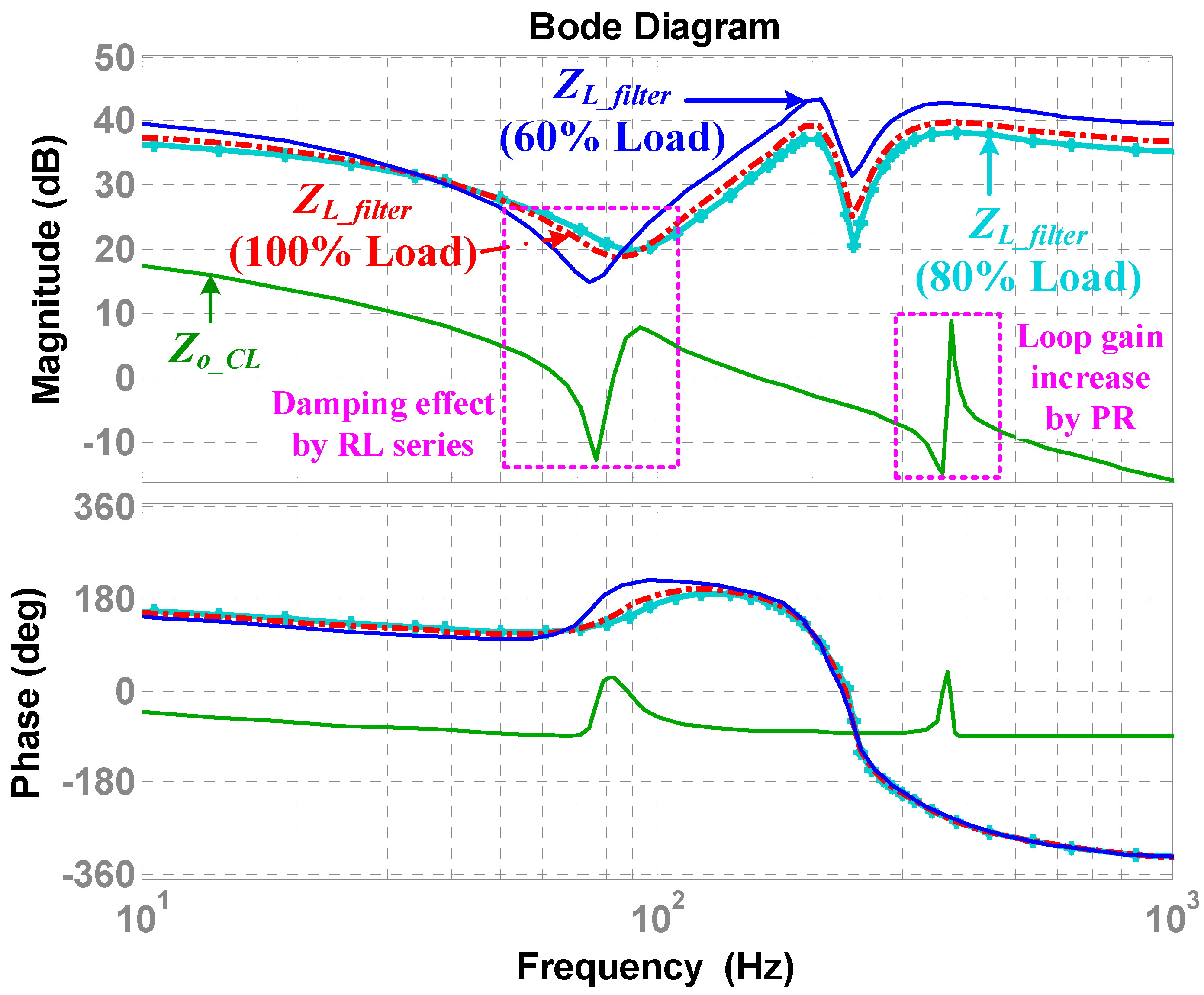
The damping method is used to prevent ringing, oscillation, and divergence, which cause the system to become unstable. The damping method related to the phase margin and the gain margin is able to improve the stability of the system through appropriate parameter tuning. To reduce the unexpected impedance overlap that causes the unstable condition between converters due to the LC of the converter, in this paper, a passive damping method, which is simple to design and implement, is applied [17]. The passive damping method is used for reshaping output impedance of the source converter, and the circuit diagram is as shown in 
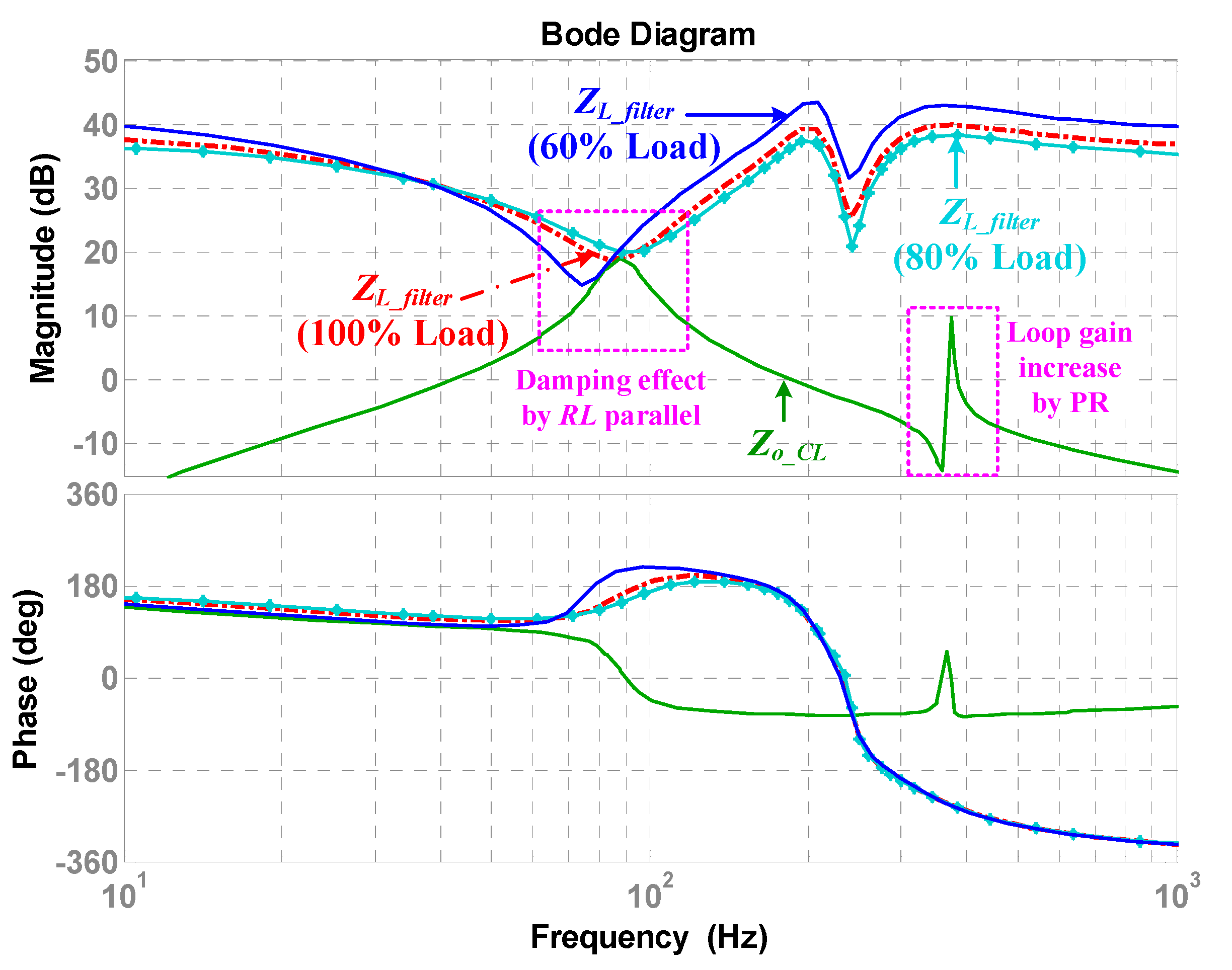
Figure 5. When passive damping method is applied, the formula of output impedance is modified by the added passive elements. As shown in Figure 5a, when RC parallel damping is applied, the output impedance changed such as in Equation (13); when RL parallel damping is applied as shown in Figure 5b, the output impedance is changed such as in Equation (14); and when RL series damping is applied as in Figure 5c, the output impedance is changed as shown in Equation (15).
Z o _ R C P ( s ) = s 3 L s C s C d R d + s 2 L s ( C s + C d R d ) + s L s s 2 ( C s C d + C s C d R d ) + s ( C d + C s + L s )
Z o _ R L P ( s ) = s 2 L s L d + s L s R d s ( L s + L d ) + R d
Z o _ R L S ( s ) = s 2 L s L d + s ( L d R d + L s R d ) s 3 L s L d C s + s 2 ( L d R d C s + L s R d C s ) + s L d R d
The modified output impedance with RC parallel, RL parallel, and 
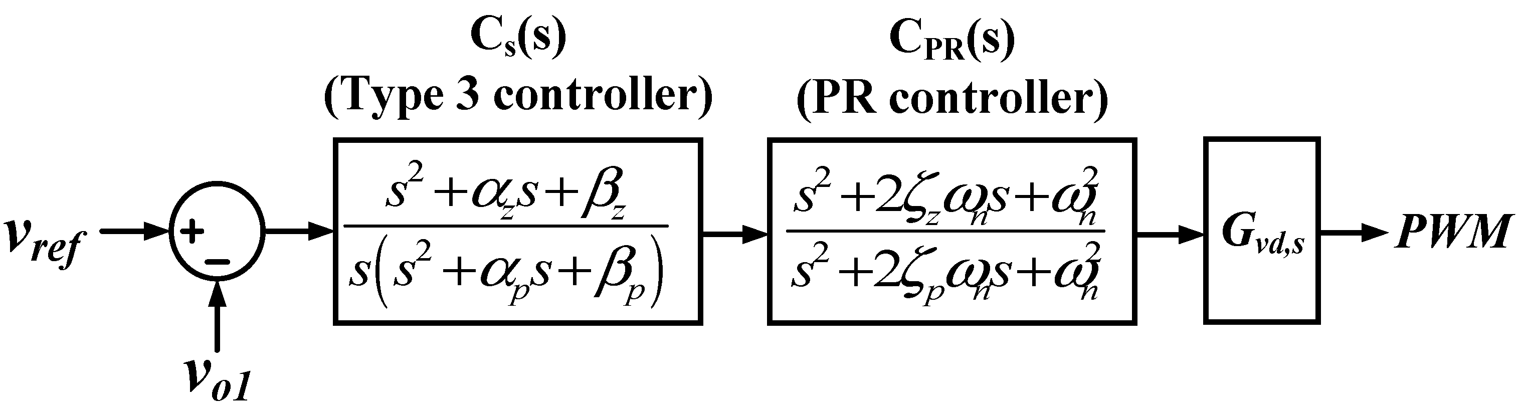
RL series damping is obtained by substituting Equations (13)–(15) into Equation (10). In addition, PR control is adopted to reduce the harmonics generated when the AC grid is interlinked. PR control is added to the existing source converter controller as shown in Figure 6. The PR controller is expressed as Equation (16), and by setting the resonance frequency with ω n , and setting ζ p and ζ z , the magnitude at the resonance point can be varied, where ζ p and ζ z indicate a damping factor of the PR controller. The loop gain of the source converter to which the PR controller is added is denoted as Equation (17).
C PR ( s ) = s 2 + 2 ζ z ω n s + ω n 2 s 2 + 2 ζ p ω n s + ω n 2
T s = C s ( s ) C P R ( s ) G v d , s ( s ) G M

4. Case Analysis

By using the output impedance derived in the previous section, a case study was conducted on ways to improve the stability of the system by reducing the unexpected impedance overlap between converters and the effect of harmonics generated from AC grid. The adopted passive damping method is shown in Figure 5, and the PR controller added to the existing controller is shown in Figure 6.

4.1. RC Parallel Damping with PR Controller

Eigenvalue analysis was performed as shown in Figure 7 to select the resistor and capacitor values for proper RC parallel damping. Figure 7a shows the waveform when the resistance is fixed at 0.01 ohm and the capacitor is changed from 1 to 50 uF. Figure 7b shows the waveform when the capacitor is fixed at 300 uF and the resistance is changed from 0.01 to 50 ohm. As can be seen from the waveform, the pole becomes closer to the origin as the capacitor value increases. As the pole moves to the LHP, it has a higher damping effect, so a value farther from the origin should be selected. In addition, since the magnitude and loss of the passive element value are correlated, an appropriate value must be selected. Therefore, in this method, the resistor is 2 ohm and the capacitor is 300 uF.
The stability analysis result is shown in Figure 8. The impedance overlap is removed by the effect of RC parallel damping, and the gain is increased at a specific frequency by the effect of PR control. Therefore, the stability of the system is improved. In addition, in Figure 9, the stability of the system is analyzed through Nyquist stability analysis. The stability is determined according to whether the Nyquist contour wraps around (−1, 0) or not. Analyzing the Nyquist waveform in Figure 9, without the RC parallel circuit, the system is unstable because the Nyquist contour wraps around (−1, 0), whereas by applying RC parallel, the system does not wrap around (−1, 0), which means it is stable.

4.2. RL Parallel Damping with PR Controller

As shown in Figure 10, resistance and inductance values for proper RL parallel damping were selected through eigenvalue analysis. Figure 10a shows the waveform when the resistance is fixed at 0.01 ohm and the inductance is changed from 1 uH to 10 mH. Figure 10b shows the waveform when the inductance is fixed at 0.1 mH and the resistance is changed from 0.01 to 50 ohm. As can be seen from the waveform, the pole becomes closer to the origin as the values of inductance and resistance increase. As mentioned earlier, the damping effect is lower when the pole is closer to the origin, so to have a high damping effect, it is necessary to appropriately select a value far from the origin in consideration of the size and loss of the passive element. Therefore, the resistance value was selected to be 3 ohms and the inductance value to be 0.1 mH.
Figure 11 shows the stability analysis by applying the previously selected RL parallel damping value. Due to passive damping and the PR controller, the impedance overlapping phenomenon is removed and the stability of the system is improved.
From the figure, it is clearly seen that the input and output impedance overlapping phenomenon is removed. In addition, the stability of the system was checked through Nyquist stability analysis, as shown in Figure 12. As can be seen from the figure, when RL parallel damping is applied, since the Nyquist contour does not wrap (−1, 0), the system is stable.

4.3. RL Series Damping with PR Controller

As with the previous methods, an appropriate damping value was selected through eigenvalue analysis, as shown in Figure 13. Figure 13a shows the waveform when the resistance is fixed at 0.01 ohm and the inductance is changed from 1 uH to 5 mH. Figure 13b shows the waveform when the inductance is fixed at 1 mH and the resistance is changed from 0.01 ohm to 5 ohm. As with the previously selected method, the value was selected to have an appropriate damping effect. Therefore, the resistance was selected as 1 ohm and the inductance was selected as 1 mH.
Figure 14 shows the stability analysis by applying the selected RL series damping value. As can be seen from the figure, the impedance overlapping phenomenon is removed by the damping effect, and the gain is increased at a specific frequency by adopting the PR controller. Therefore, the stability of the system is improved. In the same manner as previously described, Nyquist stability analysis was performed as shown in Figure 15, which shows the stability of the system is improved.

5. Simulation Analysis

To verify the proposed method mentioned in the previous section, the same circuit as in Figure 3 was configured and simulation was performed. The parameters of the system are shown in Table 1 and 
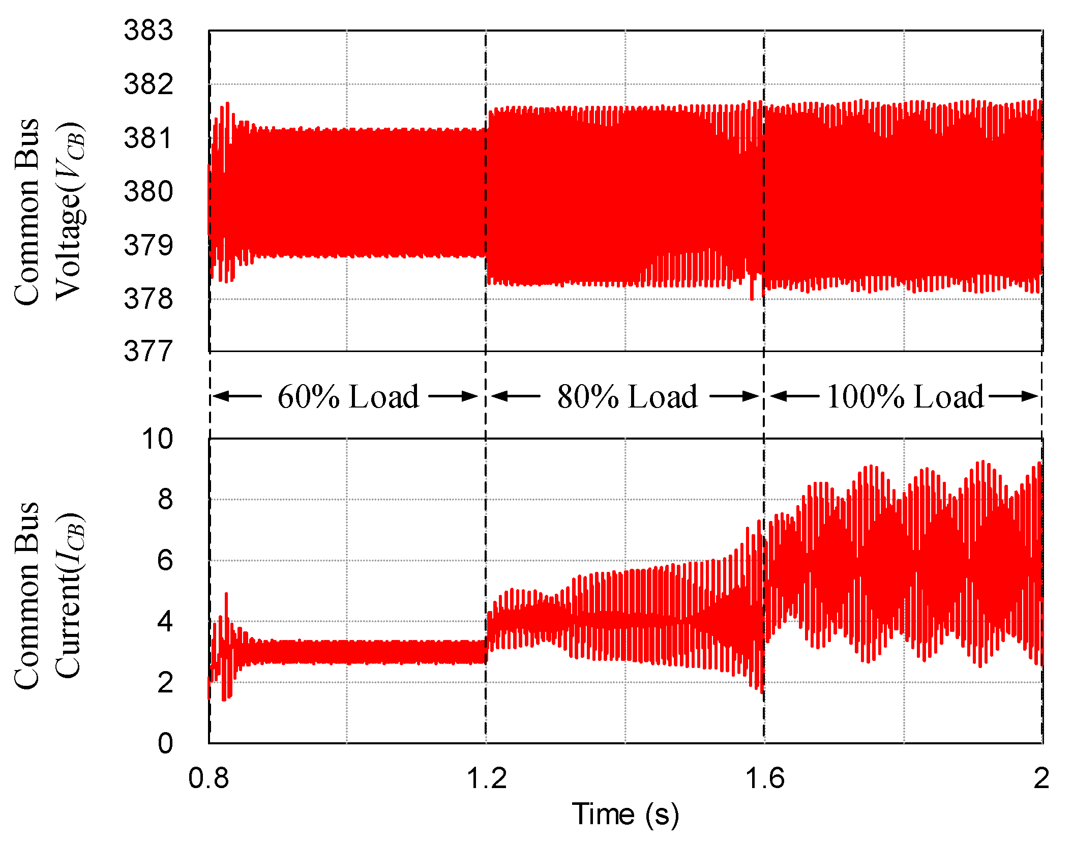
Table 2. Simulations were conducted for 60% load, 80% load, and 100% load conditions. The simulation waveform without passive damping and PR control is shown in Figure 16. Referring to Figure 16, it operates stably under 60% load condition; however, it operates unstably under 80% and 100% load condition. To remove this unstable situation, passive damping and a PR controller were added, and 
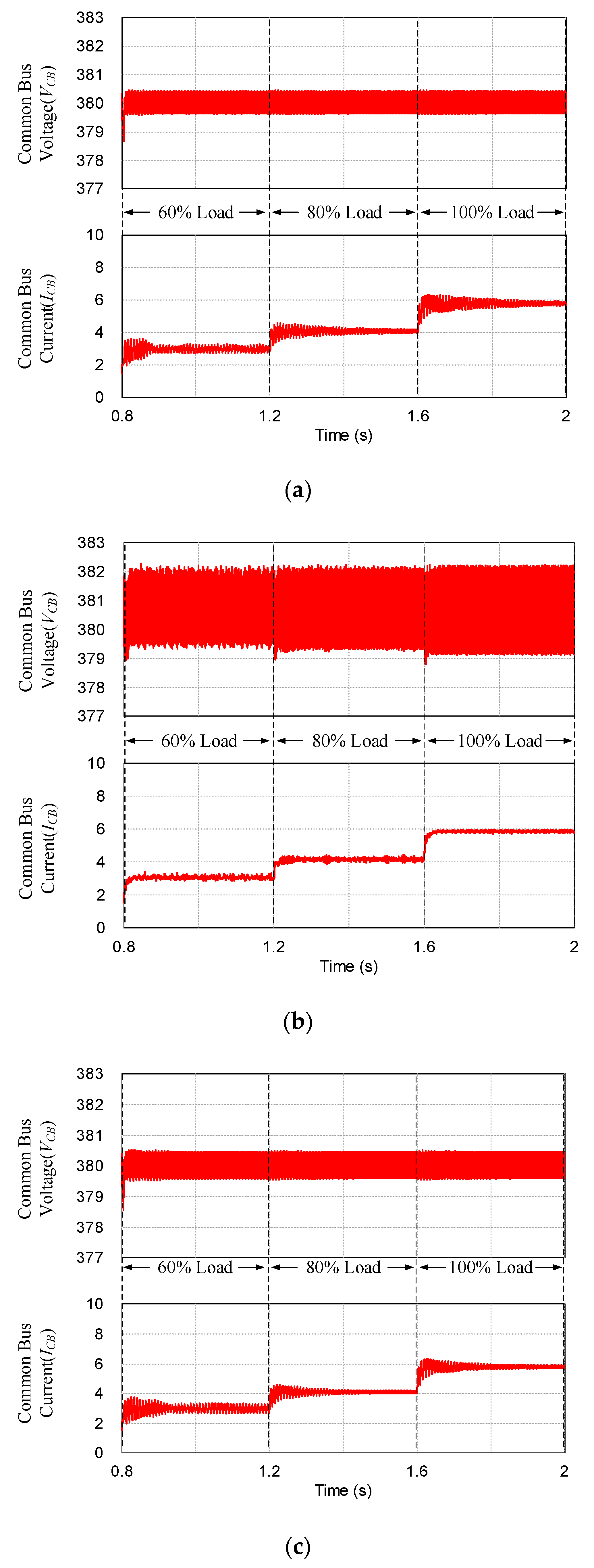
Figure 17 shows the result. Figure 17a shows the waveforms when the PR controller and RC parallel damping were applied, Figure 17b shows the waveforms when the PR controller and RL parallel damping were applied, and Figure 17c shows the waveforms when the PR controller and RL series damping were applied.
In the cases of RC parallel and RL series damping shown in Figure 17a,c, it is seen that the input and output impedance overlapping phenomenon is removed, so voltage and current ripples are remarkably reduced, and harmonics are drastically reduced because of the PR controller. In the case shown in Figure 17b, the current ripple is significantly reduced compared to the load of 80% or more in Figure 16; however, the voltage ripple is almost the same.
From the FFT analysis results in Table 3, it is seen there is a large harmonics reduction in decreasing order of RL parallel damping, RL series damping, and RC parallel damping. Through the FFT analysis, the harmonic attenuation rate of each damping method was compared to the conventional method. The harmonics decreased by 85.3% when RC parallel damping was applied, 93.3% when RL parallel damping was applied, and 85.6% when 
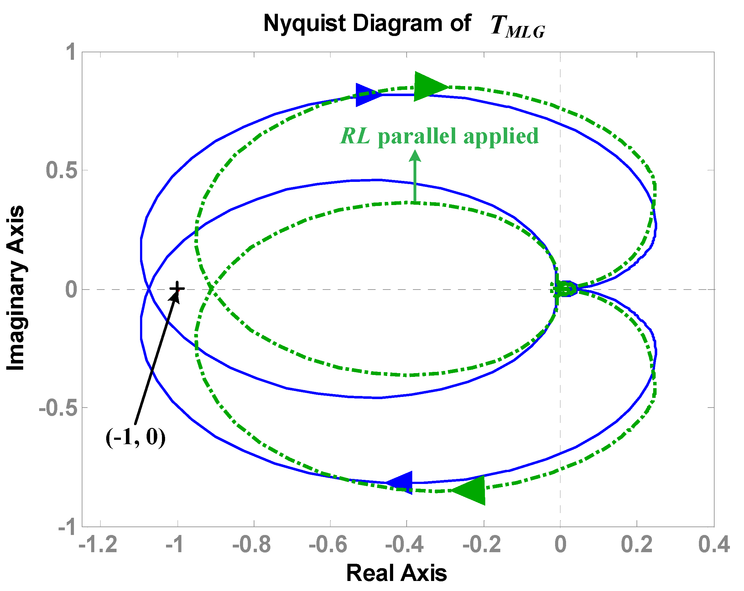
RL series damping was applied. The stability of the system was analyzed using 
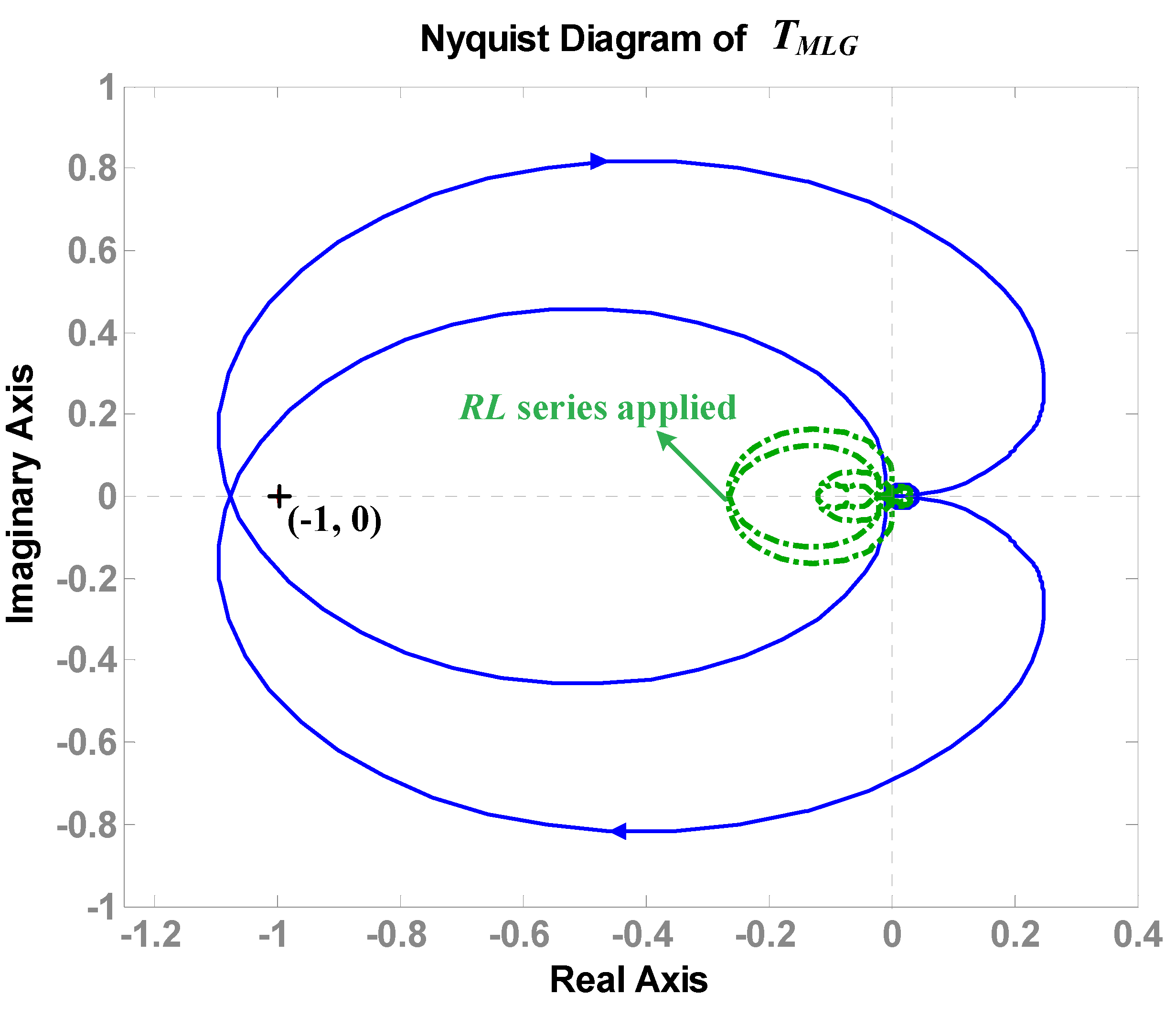
TMLG, which is the ratio of input and output impedances in a Bode plot [12,
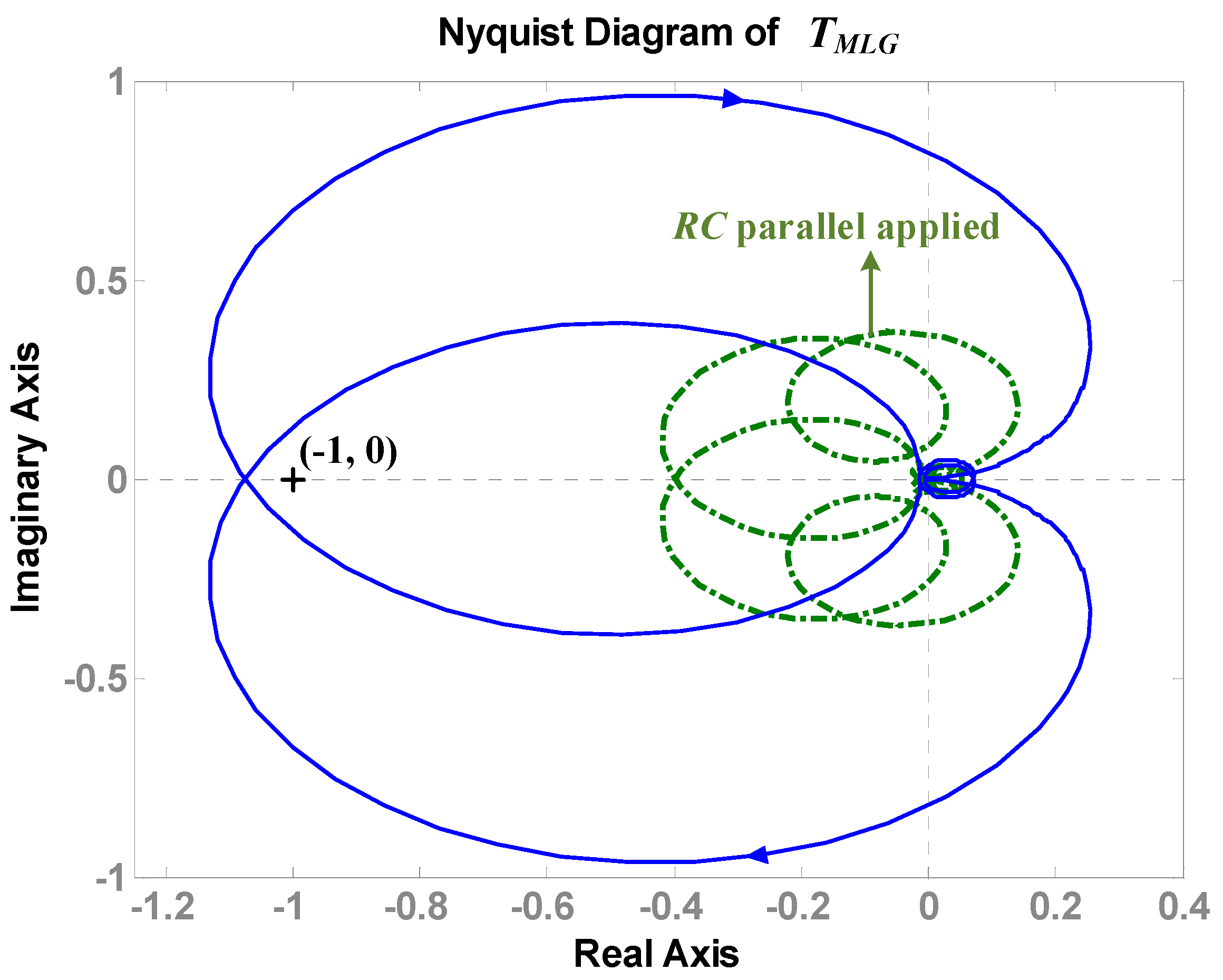
13]. As can be seen from the waveform, without applying the damping method in Figure 18, the gain margin exceeds 0 dB. This means that the system is unstable because it corresponds to the unstable condition of Middlebrook’s stability criterion in Equation (12). On the other hand, when RC parallel, RL series, and RL parallel damping methods were applied, the gain margin was below 0 dB at the same point, which means the system was stable. Through this waveform, it can be confirmed RL parallel damping has relatively higher stability than when RC parallel and RL series damping are applied.
Table 4 summarizes each damping effect through the simulation results. In short, by adopting the passive damping, the stability of the system is improved. Based on the results analyzed in this paper, if the passive damping method is applied to pre-installed microgrid power converters, it is possible to ensure the stability of the entire system according to the increase in the load and the facilities. In addition, if the active damping method described in the previous studies [12,15,16] is applied to newly installed power converters, a synergy effect in terms of securing stability can be achieved and loss problem will also be alleviated.

6. Conclusions

This paper analyzed the situation in which the system becomes unstable due to the unexpected impedance overlap between the converters constituting the DC microgrid system and the harmonics generated from AC grid. In addition, with the analysis, this paper presented a methodology to improve the system stability. To analyze the system, the stability of the system was determined by applying Middlebrook’s stability criterion and Nyquist analysis in the frequency domain. As a result of the analysis, we confirmed that there is no abnormality in the stability of the system under light load conditions, whereas when the load increases, the system becomes unstable due to impedance overlap.
In order to improve the stability of the system, RC parallel, RL parallel, and RL series passive damping methods were adopted to remove impedance overlap, and PR control was also adopted for reducing the effect of harmonics from the AC grid. The difference of each damping method was analyzed by performing a case study. In the case studies, the eigenvalue was used when selecting damping parameters taking into account the stability and loss of the system. The performance of each damping method was compared using simulation. It was confirmed that the performance of RL parallel damping was good in the case of harmonic and current ripple reduction, and the performance of RC parallel and RL series was good in voltage ripple reduction. The harmonics decreased by 85.3% when RC parallel damping was applied, 93.3% when RL parallel damping was applied, and 85.6% when RL series damping was applied.
In short, passive damping mentioned in this paper is an effective method for improving the stability of grid-tied power supplies. Though this method has disadvantages including cost and loss, it has the advantage of simple implementation, having no need for additional sensing circuits or control loops, and can be applied to pre-installed power converters. The passive damping method analyzed in this paper was applied to an installed power converter, and it was possible to secure the stability of the microgrid, which is gradually expanding in scale.

Author Contributions

Conceptualization, J.-S.L. and Y.-J.C.; methodology, J.-S.L.; software, J.-S.L.; validation, J.-S.L. and Y.-J.C.; formal analysis, J.-S.L.; investigation, J.-S.L. and Y.-J.C.; resources, Y.-J.C.; data curation, Y.-J.C.; writing—original draft preparation, J.-S.L.; writing—review and editing, J.-S.L. and Y.-J.C.; visualization, Y.-J.C.; supervision, Y.-J.C.; project administration, Y.-J.C.; funding acquisition, Y.-J.C. All authors have read and agreed to the published version of the manuscript.

Funding

This work was supported by the research grant of Jeju National University in 2021.

Conflicts of Interest

The authors declare no conflict of interest.

References

  1. Kumar, P.S.; Chandrasena, R.P.S.; Ramu, V.; Srinivas, G.N.; Babu, K.V.S.M. Energy Management System for Small Scale Hybrid Wind Solar Battery Based Microgrid. IEEE Access 2020, 8, 8336–8345. [Google Scholar] [CrossRef]
  2. Aldhaheri, A.; Etemadi, A. Impedance decoupling in DC distributed systems to maintain stability and dynamic performance. Energies 2017, 10, 470. [Google Scholar] [CrossRef]
  3. Lv, Z.; Wu, Z.; Dou, X.; Zhou, M.; Hu, W. Distributed Economic Dispatch Scheme for Droop-Based Autonomous DC Microgrid. Energies 2020, 13, 404. [Google Scholar] [CrossRef] [Green Version]
  4. Kumar, J.; Agarwal, A.; Singh, N. Design, operation and control of a vast DC microgrid for integration of renewable energy sources. Renew. Energy Focus 2020, 34, 17–36. [Google Scholar] [CrossRef]
  5. Al-Ismail, F.S. DC Microgrid Planning, Operation, and Control: A Comprehensive Review. IEEE Access 2021, 9, 36154–36172. [Google Scholar] [CrossRef]
  6. Padhilah, F.A.; Kim, K.-H. A Centralized Power Flow Control Scheme of EV-Connected DC Microgrid to Satisfy Multi-Objective Problems under Several Constraints. Sustainability 2021, 13, 8863. [Google Scholar] [CrossRef]
  7. Wahid, A.; Iqbal, J.; Qamar, A.; Ahmed, S.; Basit, A.; Ali, H.; Aldossary, O.M. A Novel Power Scheduling Mechanism for Islanded DC Microgrid Cluster. Sustainability 2020, 12, 6918. [Google Scholar] [CrossRef]
  8. Shafiee, Q.; Dragičević, T.; Vasquez, J.C.; Guerrero, J.M. Hierarchical Control for Multiple DC-Microgrids Clusters. IEEE Trans. Energy Convers. 2014, 29, 922–933. [Google Scholar] [CrossRef] [Green Version]
  9. Roldán-Porta, C.; Roldán-Blay, C.; Escrivá-Escrivá, G.; Quiles, E. Improving the Sustainability of Self-Consumption with Cooperative DC Microgrids. Sustainability 2019, 11, 5472. [Google Scholar] [CrossRef] [Green Version]
  10. Li, X.; Ruan, X.; Xiong, X.; Jin, Q.; Tse, C.K. Stability issue of cascaded systems with consideration of switching ripple interaction. IEEE Trans. Power Electron. 2018, 34, 7040–7052. [Google Scholar] [CrossRef]
  11. Lu, X.; Sun, K.; Guerrero, J.M.; Vasquez, J.C.; Huang, L.; Wang, J. Stability Enhancement Based on Virtual Impedance for DC Microgrids with Constant Power Loads. IEEE Trans. Smart Grid 2015, 6, 2770–2783. [Google Scholar] [CrossRef]
  12. Lee, J.-S.; Lee, G.-Y.; Park, S.-S.; Kim, R.-Y. Impedance-Based Modeling and Common Bus Stability Enhancement Control Algorithm in DC Microgrid. IEEE Access 2020, 8, 211224–211234. [Google Scholar] [CrossRef]
  13. Riccobono, A.; Santi, E. Comprehensive Review of Stability Criteria for DC Power Distribution Systems. IEEE Trans. Ind. Appl. 2014, 50, 3525–3535. [Google Scholar] [CrossRef]
  14. Suntio, T.; Messo, T.; Berg, M.; Alenius, H.; Reinikka, T.; Luhtala, R.; Zenger, K. Impedance-Based Interactions in Grid-Tied Three-Phase Inverters in Renewable Energy Applications. Energies 2019, 12, 464. [Google Scholar] [CrossRef] [Green Version]
  15. Hussain, M.N.; Mishra, R.; Agarwal, V. A self-switched virtual impedance based stabilization method for a droop controlled DC microgrid with constant power loads and input load filters. In Proceedings of the 2016 IEEE International Conference on Power Electronics, Drives and Energy Systems (PEDES), Trivandrum, India, 14–17 December 2016; pp. 1–6. [Google Scholar]
  16. Qu, Z.; Wang, Y.; Pan, T.; Tao, W. Stability Analysis and Active Damping Control Method of DC Microgrid Based on Solid-State Transformer. In Proceedings of the 2018 IEEE 2nd International Electrical and Energy Conference (CIEEC), Beijing, China, 4–6 November 2018; pp. 292–297. [Google Scholar]
  17. Céspedes, M.; Beechner, T.; Xing, L.; Sun, J. Stabilization of constant-power loads by passive impedance damping. In Proceedings of the 2010 Twenty-Fifth Annual IEEE Applied Power Electronics Conference and Exposition (APEC), Palm Springs, CA, USA, 21–25 February 2010; pp. 2174–2180. [Google Scholar]
  18. Lei, X.; Jian, S. Optimal damping of multistage EMI filters. IEEE Trans. Power Electron. 2012, 27, 1220–1227. [Google Scholar]
  19. Alexander, C.K.; Sadiku, M.N.O. Fundamental of Electric Circuits, 6th ed.; McGraw Hill: New York, NY, USA, 2016. [Google Scholar]
  20. Erickson, R.W.; Maksimovic, D. Fundamentals of Power Electronics, 2nd ed.; Springer: New York, NY, USA, 2001. [Google Scholar]
  21. Ahmadi, R.; Paschedag, D.; Ferdowsi, M. Analyzing stability issues in a cascaded converter system comprised of two voltage-mode controlled dc-dc converters. In Proceedings of the 2011 Twenty-Sixth Annual IEEE Applied Power Electronics Conference and Exposition (APEC), Fort Worth, TX, USA, 6–11 March 2011; pp. 1769–1775. [Google Scholar]
  22. Ahmadi, R.; Ferdowsi, M. Modeling closed-loop input and output impedances of DC-DC power converters operating inside dc distribution systems. In Proceedings of the 2014 IEEE Applied Power Electronics Conference and Exposition (APEC), Fort Worth, TX, USA, 16–20 March 2014; pp. 1131–1138. [Google Scholar]
  23. Singh, S.; Gautam, A.R.; Fulwani, D. Constant power loads and their effects in DC distributed power systems: A review. Renew. Sustain. Energy Rev. 2017, 72, 407–421. [Google Scholar] [CrossRef]
Figure 1. DC microgrid system configuration diagram.
Sustainability 13 09542 g001
Figure 2. Converter equivalent circuit using g parameters.
Sustainability 13 09542 g002
Figure 3. A simplified circuit diagram of a DC microgrid system.
Sustainability 13 09542 g003
Figure 4. Stability analysis based on impedance modeling.
Sustainability 13 09542 g004
Figure 5. Passive damping circuit diagram: (a) RC parallel, (b) RL parallel, and (c) RL series.
Sustainability 13 09542 g005
Figure 6. A control block diagram of the source converter.
Sustainability 13 09542 g006
Figure 7. Eigenvalue analysis results: RC parallel damping with PR controller: (a) Cd; (b) Rd.
Sustainability 13 09542 g007
Figure 8. Stability analysis result based on impedance modeling: RC parallel damping with PR controller.
Sustainability 13 09542 g008
Figure 9. Nyquist analysis result: RC parallel damping with PR controller.
Sustainability 13 09542 g009
Figure 10. Eigenvalue analysis results: RL parallel damping with PR controller: (a) Ld; (b) Rd.
Sustainability 13 09542 g010
Figure 11. Stability analysis result based on impedance modeling: RL parallel damping with PR controller.
Sustainability 13 09542 g011
Figure 12. Nyquist analysis result: RL parallel damping with PR controller.
Sustainability 13 09542 g012
Figure 13. Eigenvalue analysis results: RL series damping with PR controller: (a) Ld’ (b) Rd.
Sustainability 13 09542 g013
Figure 14. Stability analysis result based on impedance modeling: RL series damping with PR controller.
Sustainability 13 09542 g014
Figure 15. Nyquist analysis result: RL series damping with PR controller.
Sustainability 13 09542 g015
Figure 16. Simulation result without the stability improvement method.
Sustainability 13 09542 g016
Figure 17. Simulation result with the stability improvement methods: (a) RC parallel damping with PR controller, (b) RL parallel damping with PR controller, and (c) RL series damping with PR controller.
Sustainability 13 09542 g017
Figure 18. Stability analysis using input and output impedance ratio (TMLG).
Sustainability 13 09542 g018
Table 1. Source converter parameters.
ParameterSymbolValue
Rated powerpsource2 kW
Input voltagevs1513 Vdc
Output voltagevo1380 Vdc
InductanceLs4.3 mH
CapacitanceCs1000 uF
Switching frequencyfsw_source10 kH
Table 2. Load converter parameters.
ParameterSymbolValue
Rated powerpload2 kW
Input voltagevs2380 Vdc
Output voltagevo2190 Vdc
InductanceLL1.52 mH
CapacitanceCL330 uF
Filter inductanceLf1.5 mH
Filter capacitanceCf1000 uF
Switching frequencyfsw_load10 kH
Table 3. FFT analysis results (load: 1600 W).
Frequency (Hz)Without
Applying
Damping (A)
RC Parallel (A)RL Parallel (A)RL Series (A)
3600.4305380.0629560.0289950.061874
7200.0190890.0025210.0017390.001359
10800.0059690.0065970.0021990.005553
14400.0022830.0017940.0005670.001294
Table 4. Reduction effect of three case damping.
RC ParallelRL ParallelRL Series
Voltage ripple
reduction
HighLowHigh
Current ripple
reduction
LowHighLow
THD reductionLowHighLow
Publisher’s Note: MDPI stays neutral with regard to jurisdictional claims in published maps and institutional affiliations.

