Article

Real-Time Control Strategy of Fuel Cell and Battery System for Electric Hybrid Boat Application

1
GREAH, EA 3220, University of Le Havre, 76600 Le Havre, France
2
Electrical Department, University of Kufa, AL Najaf 54001, Iraq
*
Authors to whom correspondence should be addressed.
Sustainability 2021, 13(16), 8693; https://doi.org/10.3390/su13168693
Submission received: 26 June 2021 / Revised: 26 July 2021 / Accepted: 31 July 2021 / Published: 4 August 2021

Abstract

:
In this paper, an effective control strategy is proposed to manage energy distribution from fuel cells and batteries for hybrid electric boat applications. The main objectives of this real-time control are to obtain fast current tracking for the batteries’ system, the DC bus voltage stability by using a fuel cell, and energy load distribution for a hybrid electric boat under varying demand conditions. The proposed control strategy is based on a combination of frequency approach and current/voltage control of interleaved boost converters to reduce the hydrogen consumption by the fuel cell and improve the quality of energy transfer. The frequency approach was dedicated to managing the DC power-sharing between the load, the fuel cell, and the batteries’ storage system by extracting the power references. The closed loop control system utilized to control the energy is based on the DC/DC converters. The performance evaluation of the proposed control strategy has been tested through a real-time experimental test bench based on a dSPACE board (DS1104).

1. Introduction

Calculating the total number of boats in the world is an inexact science, but it is stated by some reports in 2017 that there are estimated to be more than 30 million recreational boats on the planet, not including cruise ships [1]. The Electric Boat and Ship Market was valued at USD 5 billion in 2020 and expected to reach USD 10 billion by 2026 registering a compound annual growth rate (CAGR) of above 11% during the forecast period (2021–2026). It is recorded that the CO2 emissions from boats form about 3–5% of the world’s CO2 emissions, which equates to about one billion tons [2].
The necessity of reducing pollutant emissions together with environmental issues requires special actions from boat manufacturers and researchers to propose alternative clean energy such as fuel cells (FCs) [3]. Thanks to the success of hydrogen fuel cells in heavy-duty vehicles, FCs (nowadays) are being integrated into different marine vessels. Fuel cells are playing the main role in reducing the greenhouse gas (GHG) emissions of marine industries on the ports and water. For marine vessels, fuel cells are the only viable, true zero-emission option. Just like batteries, fuel cells produce electricity with high efficiency through an electro-chemical process. The difference is, with a fuel cell, energy is stored separately in the form of hydrogen fuel. As long as fuel is available, the fuel cell power systems will produce electricity as a generator. The only emissions from a fuel cell are water vapor and heat.
Nearly more than 10 years ago, there was plenty of effort on hydrogen FCs to be the carbon-free future for transportation applications, such as recreational boating. Both hydrogen FCs and batteries can produce clean energy without any CO2 emissions. Although batteries are less costly than FC, hydrogen cells do not need to recharge or run down as long as there is a stable source of hydrogen [4]. However, due to the slowness of FC at starting and operation, the utilization of batteries as auxiliary sources with FC is, in fact, crucial to guarantee a smooth driving speed of the electric boats. In addition, the hybrid plane can integrate storage devices, such as a pack of batteries, to allow a significant reduction in hydrogen consumed by FC [5]. Batteries are a zero-emission power solution for smaller vessels that operate with short duty cycles. However, the lower power density and greater weight limit the use of batteries in many applications.
The hybrid energy system of FC and ESS is widely used in transportation applications such as Hybrid Electrical Vehicles (HEV) [6]. Most of the studies in [7,8,9,10] has been simulated under a different type of platform such as Simulink, SimPowerSystem, HOMER, etc. In the HEV application, FC, lithium-ion battery and ultracapacitors system was used to power the electric vehicle based on a fuzzy logic system [7]. The control of voltage and current through the DC/DC converters is based on the frequency energy management and sliding mode control.
Another nonlinear control system has been simulated to manage the power through the boost and boost-buck converters [8]. This control system has been designed to adapt the nonlinear characteristics of power electronic elements and the time-variant system. The closed loop control system has been designed to meet the requirements of system stability based on the sources (FC and SC). Various ESS has been combined with FC to ensure energy supply in the HEV, based on different topologies that respect the design of advanced charge systems [9]. A Simulink simulation has been used to carry out a mathematical model for hybrid systems consisting of FC/battery source for boat applications. The batteries are directly connected to the DC microgrid without any control, while the FC is controlled through DC/DC converters based on operation state scenarios [10]. However, most of these studies [5,6,7,8,9,10] have been modeled based on many assumptions and approximations to represent the physical operation of the system and still need to actualize.
Some other researchers have been invested in the hardware in the loop and experiments to test the control strategies applied to HEV. The supercapacitor (SC) bank has been used at a transient state of operation, in addition to the FC [11]. The Lyapunov nonlinear control method has been applied to the simulation system based on HEV to estimate the converter control parameters. The New European Driving Cycle (NEDC) has been used to evaluate the proposed energy management method through simulation tests compared to the experimental one [12]. The DC network has linked between multi-source FC, lithium batteries and ultracapacitors through DC/DC converters and an asynchronous machine through a DC/AC inverter. In [13], the authors proposed a closed loop control system to manage the distributed power between the multi-source system and load that represent the Hybrid Electric Boat (HEB). The main goal of the control system is to share the load profile between sets of two variable speed diesel generators and an auxiliary source (ESS) that is connected through the bidirectional DC/DC converter.
In 2019, the CO2 emissions are increasing to reach 1.5 billion tons because of the significant growth in demand on all fossil fuels. To avoid these emissions, many countries, such as China, Europe and the United States, are using renewable energies in the power sector. In this context, the multi-source system consisting of wind and PV with battery has been experimentally tested to minimize the generation of a diesel system [14]. The MPPT has been used to control the PV and wind while the main goal of the battery was the compensation of intermittent power fluctuations in the system. In [15], the authors proposed a hybrid system to respect the environmental concerns and respond to the energy demand. A DC/DC converter is used to integrate PV to the DC grid in case of failure in the production of wind energy delivered through a three-phase bidirectional AC/DC converter. A survey of challenges that faced the integration of renewable energy sources has been presented in [16].
Compared to other types of stored energy, both FC and ESS technologies have low environmental effects. The system based on FC has better ability to work for more operating time than batteries. On the other hand, batteries require fewer spare components and have a low price. The results of real-time monitoring on transport applications such as boats can gain a wide view of the challenges and advantages of using FC and ESS energy technologies. For this reason, FC energy and lithium-ion battery storage systems will be searched in this paper.
A hybrid electric system consisting of FC and a pack of batteries has been proposed in this paper. An efficient control strategy to manage the flow of energy between the two sources and boat power demand (load) has been presented. The system has been constructed based on the continuity of hydrogen into the fuel cell, which is considered to be the main source to provide the majority of the load whereas the Electrical Storage System (ESS) supplies the complement of the request power during the peak load and FC start up. The proposed control strategy has adopted the combination between the frequency approach and RST control system. The frequency approach has been modified to control the time constant in real-time implementation based on the health state of ESS. The main goals of this real-time control strategy are to maintain the reliability of the hybrid system and to secure the two sources from unsecured operation conditions, in addition to minimizing the hydrogen consumption.
The organization of this paper includes the configuration of the proposed hybrid system in Section 2. In Section 3, the control strategies of FC and pack of a battery system based on DC/DC converters have been detailed. Section 4 is devoted to the energy management system based on frequency approach to share the load power by controlling the DC bus voltage and the bidirectional current of the battery system. Section 5 gives a presentation of the experimental results on a reduced scale system, and finally, the conclusion remarks are described in the Section 6.

2. Structure of Hybrid Electric Boat System

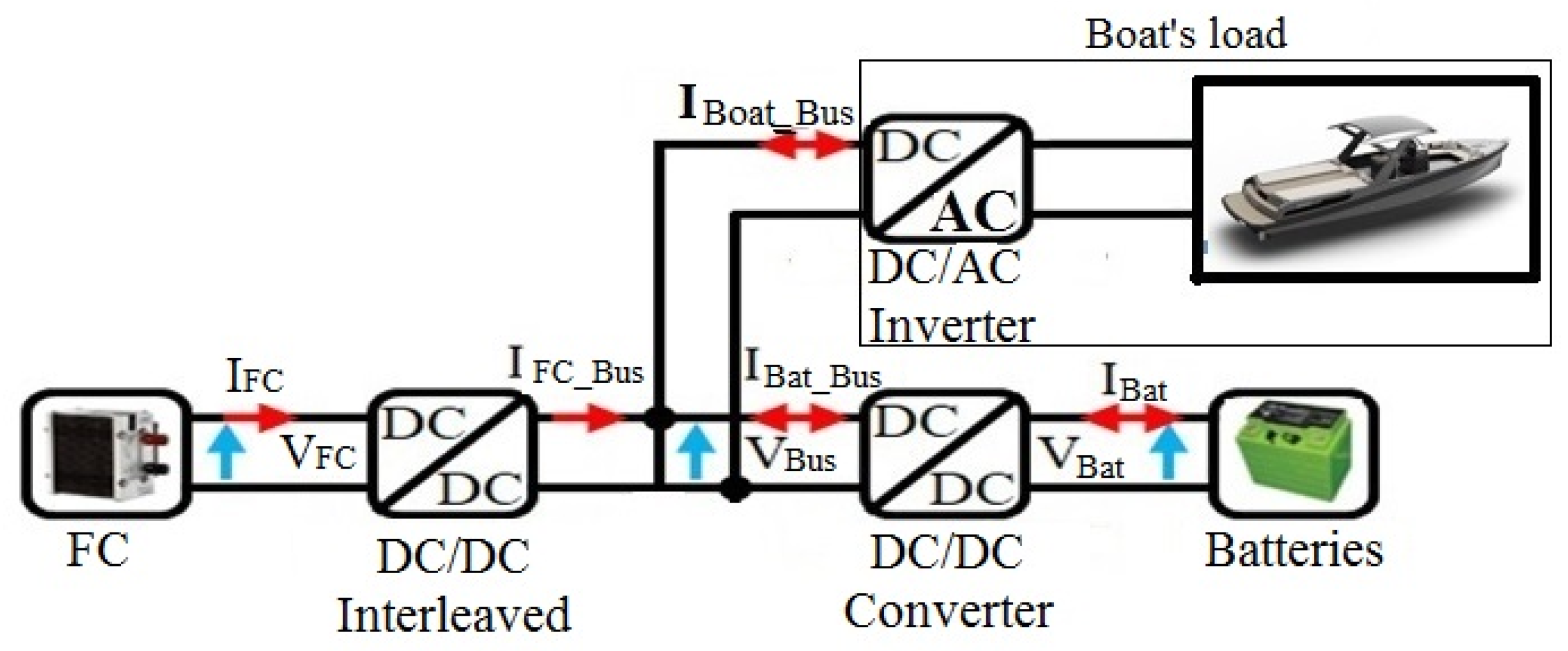
The studied HEB system presented in Figure 1 consists of two types of resources (FC combined with the lithium batteries) and the load represented by electric boat power demand. The DC grid is connected to the FC through an interleaved boost converter and a pack of batteries (power source) through a buck-boost DC/DC converter. The variable load has been linked to the DC/AC inverter as shown in the HEB system configuration.
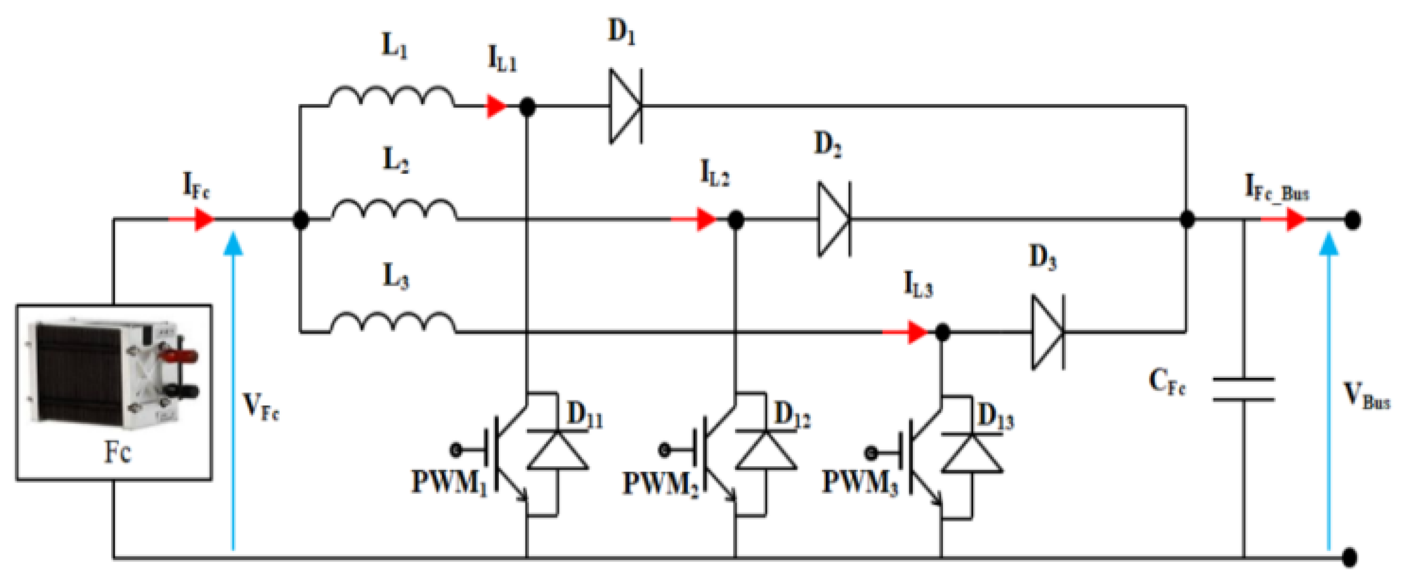
In this paper, a pack of battery storage energy is utilized to overcome the disadvantages of the slow operation of the FC (especially at startup). The main contribution of the FC source is to control and maintain the continuity of DC bus voltage with or without output current of ESS. In addition, the DC energy supplied from the FC of the proposed system is based on interleave boost converters because of their advantages such as higher efficiency, reduced ripple currents, and substantially reducing losses.
The batteries can contribute to providing appropriate and smooth DC power generation for boat and reduce the amount of energy required from the FC source. The DC/DC and DC/AC converters are used for current control to improve the quality of energy transfer, to reduce the hydrogen consumption by the FC, using ESS in real-time conditions. Batteries ESS capacity was determined to be able to store the energy from FC source at charging time and return it at discharge time to meet the fast shortages in demand.
The load profile of HEB is proposed to represent boat freight transport with rated 60 kW from Le Havre to Paris in France.

3. Simulation of Power Control Strategy

3.1. Control Strategy for Bus Link Voltage

The DC energy produced by FC has been controlled through the interleaved boost converter that is connected to the DC bus link. The main objective of this control strategy is to stabilize and maintain the DC bus voltage during the load variation and to keep the FC as the primary source in this system. The boost interleaved converter protects the FC source from any revert energy during regeneration status by ESS. The topology of the three-phase interleaved boost converter shown in Figure 2 consists of three parallel switches controlled by Pulse Width Modulation (PWM) signals with three freewheeling diodes for each phase with three same inductances and three diodes in series.
The three switches are used to improve the output waveform and increase the delivery power of the converter. During the design of interleaved converter, the size of the converter filter is considered to reduce the ripple of the output current of the three paths. In order to take advantage of the three IGBT switches on the control design, the three PWM signals are phase shifted by 120° as shown in Figure 3. The ratio of the input current ripple to the current ripple is often used as a comparison criterion between different interleaved boost converter topologies [17].
The model of a three-phase interleaved boost converter can be represented by the following three equations:
{ L 1 · d I L 1 d t = V F C ( 1 1 ) · V B u s L 2 · d I L 2 d t = V F C ( 1 2 ) · V B u s L 3 · d I L 3 d t = V F C ( 1 3 ) · V B u s
where V F C is the fuel cell voltage (measured in V); is the duty ratio of PWM signal; L is the inductance (measured in mH); V B u s is the DC Bus link voltage in (measured in V); i L 1 is the current of conductance (measured in A); d t is the change of time in second.
The proposed control of voltage control is based on the RST polynomial method that requires tracking the reference voltage. The synthesis of this method can define the overshoot and the rise time of the measurement but has to take into account the delays as well as the nature of the disturbances and the set points [18,19]. The RST polynomial controller offers better respond and robustness toward the parametric variations in comparison with a PI controller [20].
In order to achieve minimal static error with disturbance rejection, the RST polynomials used for DC bus voltage control are presented by the following equations:
{ S F C ( z 1 ) = 1 z 1 T F C ( z 1 ) = R F C ( z 1 ) = t 0 F C + t 1 F C · z 1 t 0 F C = 2 · (   1 e ω F C · T e ) · C T T e t 1 F C = (   e ω F C · T e 1 ) · C T T e C T = C F c + C B a t
where T e is the sampling period, ω F C represent the bandwidth for controlling the voltage, C T is the total capacitance in the bus.
In HEB, the voltage bus should be kept constant, which is considered in this control to be the voltage reference. In addition, the FC is the main principle that controls the DC bus voltage through the linked interleaved boost converter. Indeed, the current of the FC source is not controlled and will be imposed by the evolution of the system. That means, the FC current is deduced from Kirchhoff’s current law and equal to the load current after subtracting the contributions from the pack of batteries, it can be calculated by:
I F c = V B u s V F C · I F C _ B u s
The main construction of RST voltage control with Anti-windup that used in the different controller to minimize performance degradation has shown in Figure 4.

3.2. Control Strategy of the Current System

In this section, the main principle of the control strategy is based on sharing of the load’s current between FC and a pack of batteries. Therefore, the HEB load profile and the FC limited generation have been studied to select the size and number of batteries required [21]. The main factors have been considered to determine the rated power output of batteries were the maximum difference of the output power of FC and HEB load, the maximum value of stored power, and the searched over the duration of SoC.
The ESS power control sub-system includes the pack of batteries interfaced with a buck/boost converter to control the current between the DC bus and batteries. Lithium-ion batteries have been considered in this study because of their high energy density and efficiency in comparison to the other battery types such as NiMH, NiCd, or lead-acid. The battery output voltage is considered to be nonlinear functional because of the battery’s state of charge (SoC) and the nonlinear current. The battery’s voltage V B a t is calculated by using the following equation [22].
V B a t = V o p R B a t i B a t K b Q Q i t . i t + A b e B . i t K b Q Q i t . i *
where V o p is the voltage of open circuit, i B a t is the current of open circuit, R B a t is the total internal resistance of batteries, Q is the total capacity of batteries, K b is polarization constant, i * is filtered current of batteries, B is exponential capacity, i t is actual charge batteries current, A b is exponential voltage.
The term ( K b Q Q i t . i t ) is called the polarization voltage that affect the SoC, which reflects the performance of the battery. The SoC of batteries plays the main role in stabilizing the bus voltage of DC link and buffering the power fluctuations. The battery voltage during the charging state increases after the pack of batteries is fully charged and referred to the polarization resistance ( P o l r e s ) that can be found by:
P o l r e s = K Q i t 0.1 Q
According to the above parameters, the model of the Li-ion battery can be represented as in Figure 5.
In this HEB system, the load profile of the boat is only at the positive part, which means there will be only one direction of current pass from the DC link to the boat’s load through the DC/AC converter and has no reverted current. In FC source with a high voltage gain needs controller connected to an interleaved DC/DC boost converter to ensure their optimal operation and maintain the voltage of the DC link constant.
ESS units are connected to the DC bus via bidirectional DC/DC converters as shown in Figure 6. The reference current for the pack of batteries is obtained from the implemented frequency management approach and from the power balance linked to the converter as expressed in the following equation, where the losses in the converter are neglected:
I B a t = V B u s V B a t I B u s b a t
In buck-boost converter, the battery current is controlled by changing the value of the duty cycle rate ( ) in both cases buck and boost. Normally, the duty cycle changed from 0 to 1 but increases the response time and protects the IGBT devices; it is recommended to limit these values according to the maximum and minimum voltage of the batteries.
B u c k _ B a t = V B a t + V c o n t r o l _ l o o p _ o u t p u t V B u s
B o o s t _ B a t = 1 V B a t V c o n t r o l _ l o o p _ o u t p u t V B u s
At the load side, the same control technique has been used to control the current in the DC link side, according to the changes on the load profile through the frequency approach to manage the energy from sources as shown in Figure 7.

4. Frequency Approach for Control Strategy

The control of power is unidirectional for the fuel cell and load, while for the pack of the batteries is bidirectional. The distribution of power into the DC grid is controlled by using the frequency approach, which considers the power balance, state of charge (SoC) for batteries, and the limited power of FC and batteries. All these constraints can be described by the following equations:
Power balance:
P F C ( t ) ±   P B a t ( t ) = P L o a d ( t )
SoC:
S o C m i n ( t )   S o C ( t )   S o C m a x ( t )
FC power limits:
P F C   m i n ( t )   P F C ( t )   P F C   m a x ( t )
Pack of batteries power limits:
P B a t   m i n ( t )   P B a t ( t )   P B a t   m a x ( t )
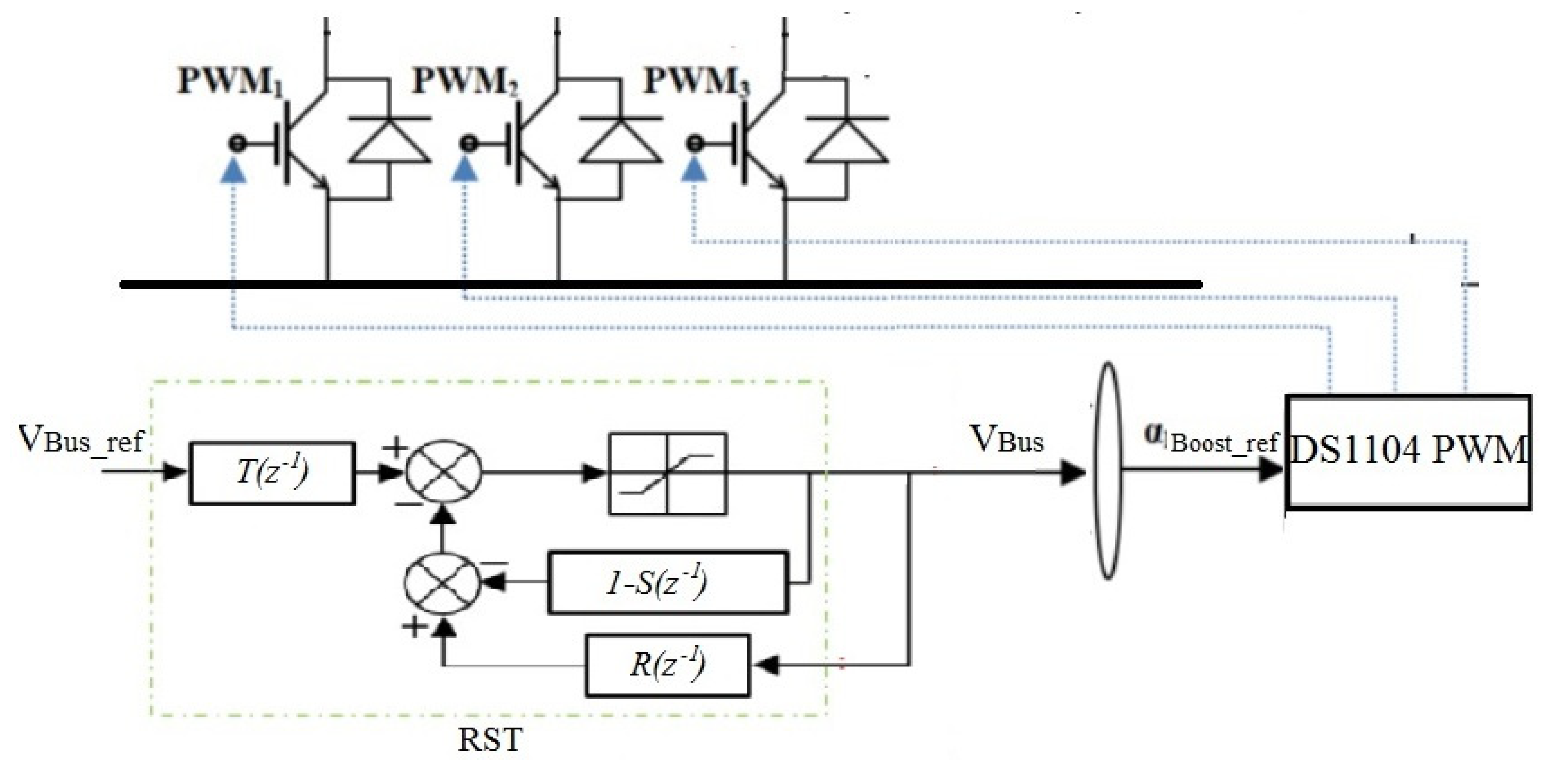
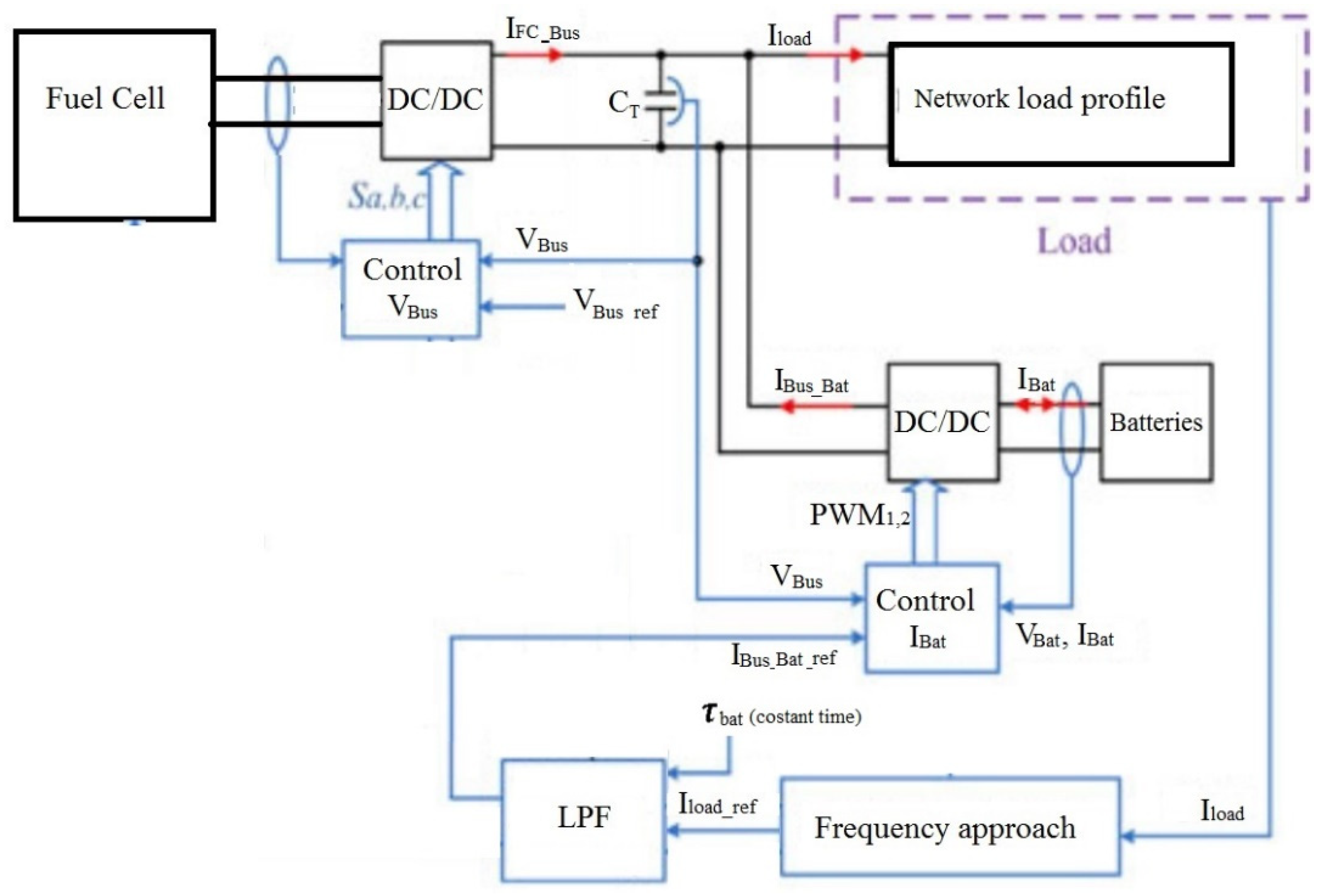
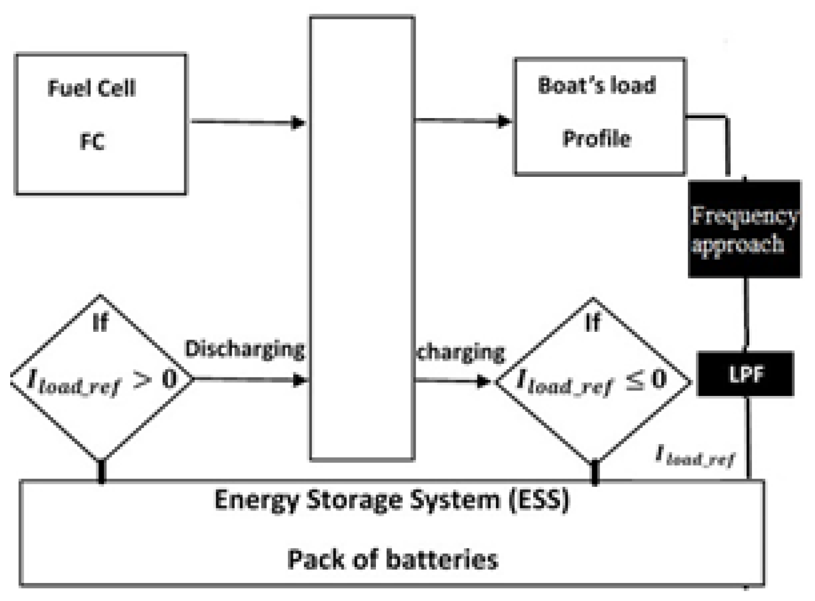
This control strategy is based on three main control systems to determine the switch state of the converters and on-times as shown in Figure 8. It has been proposed to control these dynamic interactions by taking into account the frequency content of the fluctuations. If the DC bus voltage is controlled to a constant value, the disturbances will be transferred to the currents.
The current reference of batteries is extracted from the load demand using the low-pass filter (LPF) based on DC bus voltage controller as shown in Figure 9. Due to profile variances for boats’ demand in terms of start and operation status, the batteries current reference ( I B a t _ r e f ) will use to control the state (buck/boost) of DC/DC converter at the side of the pack of batteries. The current control system is based on the changes of converter operation mode. The converter mode is operated as the follow principle: If sign I B a t _ r e f > 0 , the converter operates in boost mode and pack of battery supply energy to DC-bus. Otherwise, the converter operates in buck mode and batteries store energy.
The approach of low-pass filter (LPF) has been determined by identifying the functions as described in Figure 10. This method has been developed to control the time constants of the filter during the real-time operations, according to the healthy state of batteries such as SoC, capacitance and resistance. The currents of load are broken down into low frequency components to estimate the reference of battery power and high frequency ones, where the component of the high frequency is utilized to estimate the FC current.
The parameters of the functions that define the control of LPF time constant can be expressed as follows:
{ F u n c t i o n 1 ( x , τ B a t ) = x . T s   ( 1 + z ) ( T s   + 2 τ B a t ) z F u n c t i o n 2 ( x , τ B a t ) = τ B a t ( 2 x T s   ) ( T s   + 2 x ) z τ B a t ρ e B a t 2 π ρ p B a t =   E n e r g y B a t 2 π P o w e r B a t

5. Simulation Results for Frequency Approach

To demonstrate the feasibility of the HEB, the simulations of the energy management strategy are done using Matlab/Simulink software. The rated power for the simulated system is considered as 60 kW, and all other parameters for the rest of the system are detailed in Table 1. These parameters are obtained from the data sheet of the battery [24], from previous work [25] and the setting for the control system.
The adopted energy management splits the load energy demand into several components according to the number and nature of the onboard energy sources. In this HEB case, the system contains two energy sources: fuel cells and a pack of batteries. The fuel cells stack has lower dynamic performance compared to the battery pack. Therefore, the Fc contribution will cover the low frequency component extracted from the load current demand, furthermore the Fc stack is considered to be the system’s main source, and the DC-bus voltage is controlled through it.
On the other hand, the high frequency component is ensured by the battery pack because it benefits from higher dynamic characteristics than the Fc, and it is considered to be an auxiliary energy source. The load current separation is performed using a low pass filter.
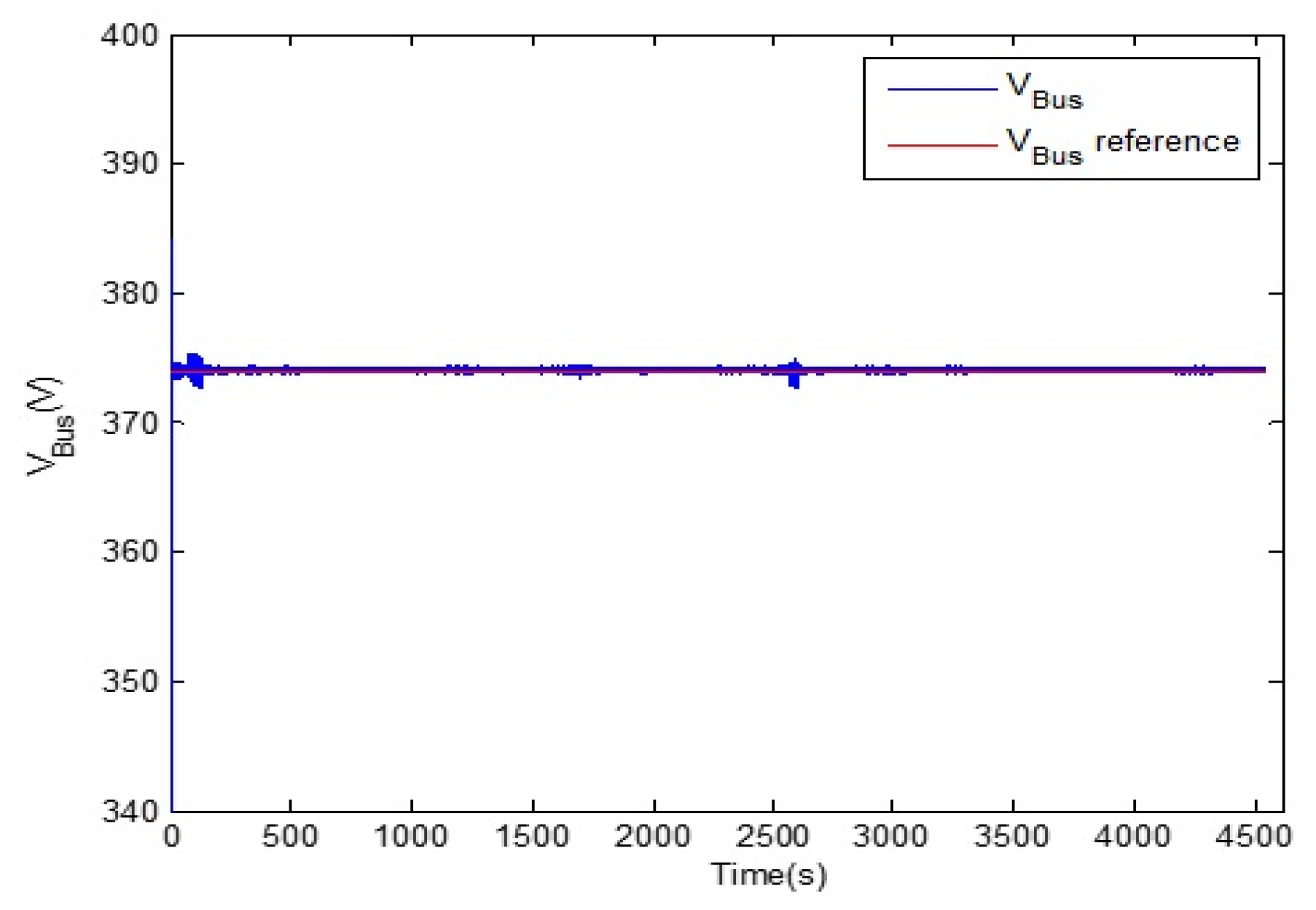
In this simulation, the DC-bus voltage is set to a constant point as shown in Figure 11, so that the current flows through the bus link to share the load demand with the multi-source system (fuel cells stack and battery pack) according to the proposed modified frequency separation approach. The implemented voltage control strategy maintains the DC-bus voltage around the constant reference value. For this simulation, the VBus reference value is fixed to 374 V. According to the simulation result, the voltage control is satisfied since the measure is very close to the set point with minor fluctuations due to the load current variations.
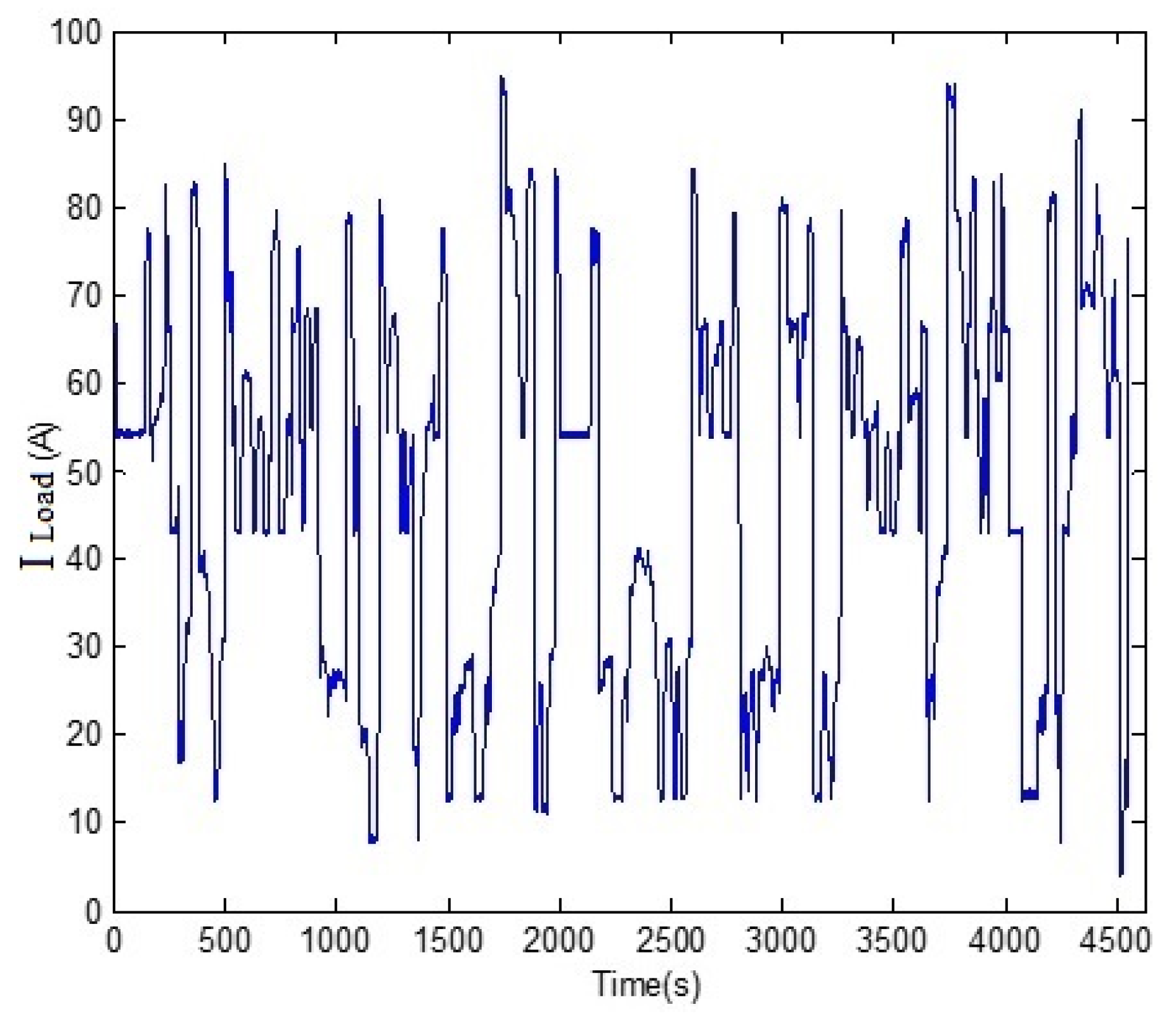
Figure 12 shows the profile of HEB for the total duration (4572.5 s) with a high peak of 95 A and minimum current of 2 A.
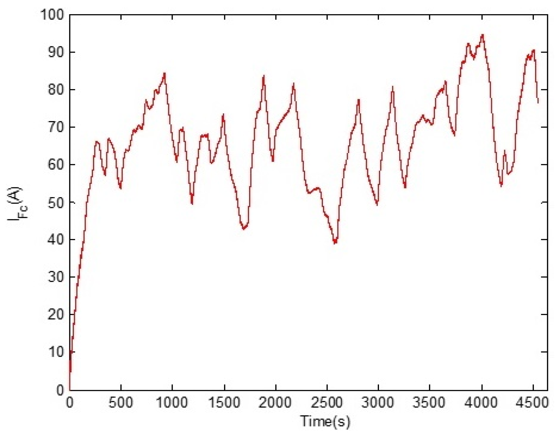
Figure 13 shows the Fc stack current contribution, which represents the low frequency component of the load power requirement. Compared to the batteries and the load ones, IFc frequency variation is moderate. The 
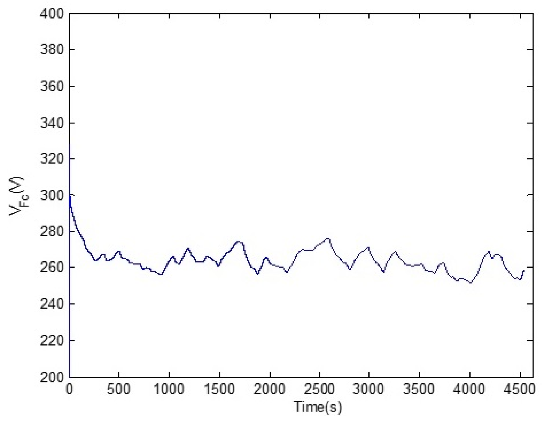
Fc stack terminal voltage is illustrated in Figure 14. Regarding the voltage response, and beside the first voltage drop due to Fc voltage activation, V F C does not fluctuate significantly compared to V b a t ; this means that the FC stack is not requested during transient load states.
The battery pack current and voltage are presented, respectively, in Figure 15 and Figure 16. The battery pack ensures the high frequency of the load power requirement. It can be noted from the above figures that when there is a considerable load demand, it will cause a fast-discharging current from the battery. On the other hand, during large load power drops, the battery voltage increases due to the recovered current. Finally, when the load demand is stable with no high frequency solicitations, the battery voltage is stable.

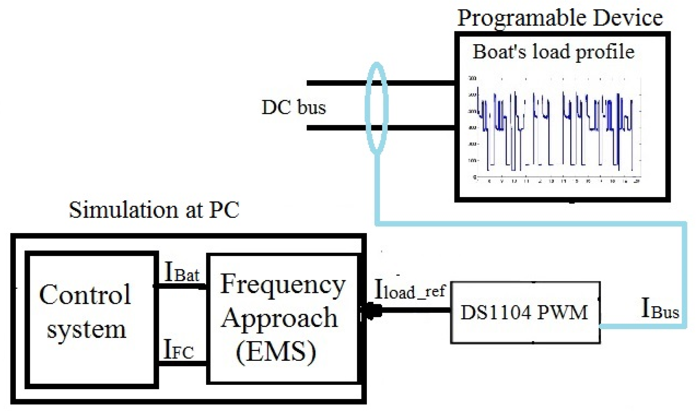
6. Experimental Verification of the Control Strategies

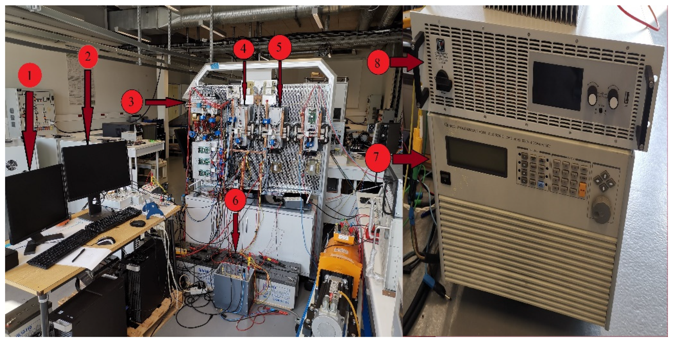
According to the available equipment in the laboratory, the tests are done on a reduced scale of 71. The experimental test bench as shown in Figure 17. The system consists of two PC systems (1 and 2) that are used to control and measure the test bench. The fuel cell (8) is connected through the interleaved boost converter (3) to the DC bus supplied by a pack of batteries with a total of 500 Ah (6) through DC/DC buck-boost converter (5). The pack of batteries consists of five batteries type LiFePO4 in the series each has 12 V/100 Ah. The load profile (7) has been implemented in programmable DC load (4) which is linked in the DC bus link through the unidirectional buck converter (4).
The voltage reference of the DC bus was fixed to 105 V due to limited voltage of the batteries, while the FC voltage source was 70 V. The output current of the FC system is covered by the high frequency components for the frequency approach based on load reference current. The parameters of HEB system used in the test bench are presented in Table 2.
The power management between the FC and pack of batteries sources of the HEB has been developed based on the performance of individual energy sources and the suitable controllers for each of them have been adopted. The main principle of the energy management system has been done in Figure 18. The pack of batteries and FC source must share the power with variable load in order to maintain the power balance in the HEB system. The control strategies are based on extracting voltage and current references for FC and batteries, respectively.
During the startup and rapid demand, the power output of the FC source cannot follow the power load required. The deficit of power in these conditions will fluctuate the frequency on the HEB that leads to the current reference for a pack of batteries to discharge batteries depending on the magnitude of deficit current. The batteries cells absorb the additional power as storage energy. If the production power exceeds the maximum capacity of storage batteries, the control system of interleaved boost converter needs to decrease the FC output power to maintain the stability of the DC bus link voltage.
In Figure 19, the experimental test shows that the proposed control of DC bus voltage has been maintained around the set point as a reference, with some acceptable error in measurements. The PC1 is used to implement and control the real-time simulation through the Dspace (DS1104 controller) by changing the ratio of duty of IGBT by controlling for PWM for the interleaved boost converter. The measurement of voltage bus has been used to track the reference value required.
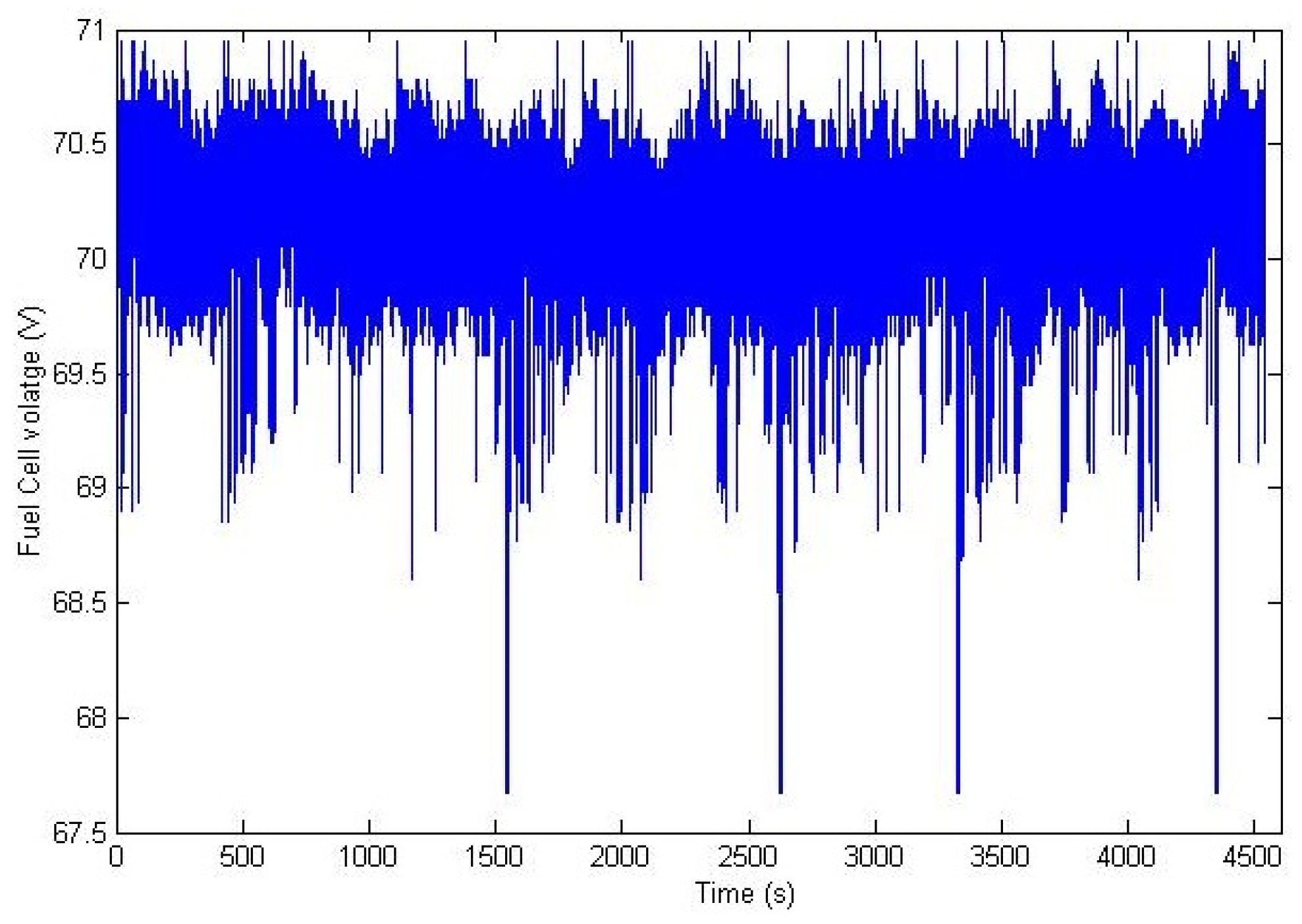
The FC voltage results are presented in Figure 20, which is close to the limit voltage requested (70 V). The interleaved boost converter has been controlled to determine the direction and amplitude of current between the DC bus and the fuel cell source as shown in Figure 21.
The profile has been rescaled according to the laboratory equipment after adding some noise to have dynamic performance. The variation of demand has been controlled in real-time implementation to track the profile of boat’s load, as presented in Figure 22. The maximum and minimum current of load demand is 8 and 0.7 A, respectively. It shows that the fluctuations of current from the load have been controlled by the PC2 through another Dspace (DS1104 controller) to obtain the best correction between the simulated load profile and the production required for the real-time implementation.
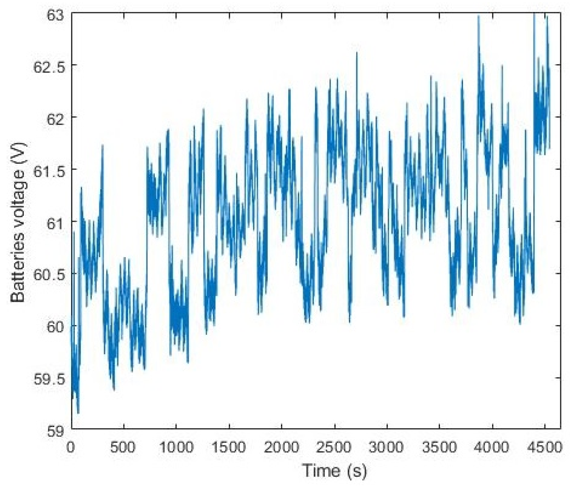
The control strategy of the batteries’ current is based on the RST method to track the current reference extracting from the proposed modified frequency approach. The constant time of frequency approach has been calculated by the simulation part at 189 s taking into account the healthy state of the pack of batteries. The result of battery voltage control with the state of charge management during HEB operation is illustrated in Figure 23. The battery controller keeps the voltage limitation less than maximum value and more than minimum value to avoid the batteries’ deterioration. The unpredictable battery voltage depends on the components of high frequency for load current.
When I b a t _ r e f is in the charging status (negative areas), the exceeding production of energy is stored in the batteries. Otherwise, in the discharge status (positive areas), the storage energy is used to ensure the compensation of this energy. The real-time simulation in PC2 sends the PWM for IGBTs into the converter to control the buck-boost converter. The state of the converter as buck or boost is determined according to the sign of current reference extracting from the modified frequency approach. The ratio of a duty cycle is controlled by the RST method to track the reference current required and its direction is shown in Figure 24. The amplitude of batteries current is fluctuating between positive and negative parts to determine the buck and boost state, respectively.

7. Conclusions

This paper presents the study of an HEB based on FC source and storage batteries. To achieve an efficient energy production of the proposed system, the energy management was based on maximizing the share of the pack of batteries and minimizing the contribution of the FC source. Since the energy produced by FC is slow at the startup and has rapid load changes, the producing energy is supplied by the ESS. A set of the batteries was connected to the DC-bus link through DC/DC buck-boost converter in order to compensate for the fluctuations of high frequency current from FC sources. The time constant of the frequency approach has been selected for an efficient management system based on the health state of the batteries and load profile. The simulations evaluated the performances of the proposed modified frequency approach to demonstrate its ability to respect the SoC conditions of batteries. The performances of the proposed DC grid concept are validated through the experimental tests, using dSPACE real-time platform (CP1104) to demonstrate the feasibility of the HEB. The results from the experimental tests in reduced scale are satisfactory and show the efficiency of the proposed control strategy.

Author Contributions

Conceptualization, A.A.A., M.B.C.; methodology, A.A.A., M.B.C.; software, A.A.A., M.B.C. and I.O.; validation, A.A.A., M.B.C. and I.O.; formal analysis, A.A.A., M.B.C.; investigation, A.A.A., M.B.C.; data curation, A.A.A., M.B.C.; writing—original draft preparation, A.A.A., I.O.; writing—review and editing, A.A.A., M.B.C. and I.O.; visualization, A.A.A., M.B.C.; supervision, M.B.C., B.D.; project administration, M.B.C., B.D.; funding acquisition, M.B.C., B.D. All authors have read and agreed to the published version of the manuscript.

Funding

The council of Normandy Region (France) has funded this article.

Institutional Review Board Statement

Not applicable.

Informed Consent Statement

Not applicable.

Data Availability Statement

The data presented in this study are available on request from the corresponding authors.

Acknowledgments

This work was supported by the University of Le Havre Normandy and is funded by the Normandy region in France. The project handles energy concerning CO2 emissions and adopting technologies of low pollution such as Hydrogen Energy, Fuel Cell, and batteries.

Conflicts of Interest

The authors declare no conflict of interest.

Nomenclature

PnPMSG rated power
RtRadius of the wind turbine
ρAir density
RsPMSG resistance
LsInductance of the PMSG
JTotal moment of inertia for a wind
UsefLine to line RMS voltage in the stator
VdcrefDC-bus voltage reference
Rres; LresGrid parameters
R; LParameters of the filter
CDC-bus capacitor
φMagnetic induced flux
τPitch actuator time constant

References

  1. European Commission. The EU Blue Economy Report 2019; European Commission: Brussels, Belgium, 2019. [Google Scholar]
  2. International Renewable Energy Agency. Navigating the Way to a Renewable Future: Solutions to Decarbonise Shipping; International Renewable Energy Agency: Abu Dhabi, UAE, 2019. [Google Scholar]
  3. Cruz-Pérez, N.; Santamarta, J.C.; Rodríguez-Martín, J.; Ioras, F.; Bruccoleri, M. Incamp: Master’S Degree in the Carbon Neutral Management of Sport Marinas. In Proceedings of the EDULEARN20 Proceedings, Online Conference, 6–7 July 2020; Volume 1, pp. 151–156. [Google Scholar]
  4. IEA. The Future of Hydrogen for G20; IEA G20: Paris, France, 2019. [Google Scholar]
  5. Balestra, L.; Schjølberg, I. Modelling and simulation of a zero-emission hybrid power plant for a domestic ferry. Int. J. Hydrog. Energy 2021, 46, 10924–10938. [Google Scholar] [CrossRef]
  6. Khaligh, A.; Li, Z. Battery, ultracapacitor, fuel cell, and hybrid energy storage systems for electric, hybrid electric, fuel cell, and plug-in hybrid electric vehicles: State of the art. IEEE Trans. Veh. Technol. 2010, 59, 2806–2814. [Google Scholar] [CrossRef]
  7. Snoussi, J.; Ben Elghali, S.; Benbouzid, M.; Mimouni, M.F. Auto-adaptive filtering-based energy management strategy for fuel cell hybrid electric vehicles. Energies 2018, 11, 2118. [Google Scholar] [CrossRef] [Green Version]
  8. El Fadil, H.; Giri, F.; Guerrero, J.M.; Tahri, A. Modeling and nonlinear control of a fuel cell/supercapacitor hybrid energy storage system for electric vehicles. IEEE Trans. Veh. Technol. 2014, 63, 3011–3018. [Google Scholar] [CrossRef] [Green Version]
  9. Sharma, S.; Panwar, A.K.; Tripathi, M.M. Storage technologies for electric vehicles. J. Traffic Transp. Eng. 2020, 7, 340–361. [Google Scholar]
  10. Han, J.; Charpentier, J.F.; Tang, T. An energy management system of a fuel cell/battery hybrid boat. Energies 2014, 7, 2799–2820. [Google Scholar] [CrossRef] [Green Version]
  11. Nazir, M.S.; Ahmad, I.; Khan, M.J.; Ayaz, Y.; Armghan, H. Adaptive control of fuel cell and supercapacitor based hybrid electric vehicles. Energies 2020, 13, 5587. [Google Scholar] [CrossRef]
  12. Tani, A.; Camara, M.B.; Dakyo, B. Energy management based on frequency approach for hybrid electric vehicle applications: Fuel-cell/lithium-battery and ultracapacitors. IEEE Trans. Veh. Technol. 2012, 61, 3375–3386. [Google Scholar] [CrossRef]
  13. Zhou, Z.; Camara, M.B.; Dakyo, B. Coordinated power control of variable-speed diesel generators and lithium-battery on a hybrid electric boat. IEEE Trans. Veh. Technol. 2017, 66, 5775–5784. [Google Scholar] [CrossRef]
  14. Lawan, M.M.G.; Raharijaona, J.; Camara, M.B.; Dakyo, B. Power control for decentralized energy production system based on the renewable energies—Using battery to compensate the wind/load/PV power fluctuations. In Proceedings of the 2017 6th International Conference on Renewable Energy Research and Applications, ICRERA 2017, San Diego, CA, USA, 5–8 November 2017. [Google Scholar]
  15. Kumar, M.; Singh, S.N.; Srivastava, S.C. Design and control of smart DC microgrid for integration of renewable energy sources. In Proceedings of the IEEE Power and Energy Society General Meeting, San Diego, CA, USA, 22–26 July 2012. [Google Scholar]
  16. Badal, F.R.; Das, P.; Sarker, S.K.; Das, S.K. A survey on control issues in renewable energy integration and microgrid. Prot. Control Mod. Power Syst. 2019, 4, 1–27. [Google Scholar] [CrossRef] [Green Version]
  17. Uno, M.; Inoue, M.; Sato, Y.; Nagata, H. Bidirectional Interleaved PWM Converter with High Voltage-Conversion Ratio and Automatic Current Balancing Capability for Single-Cell Battery Power System in Small Scientific Satellites. Energies 2018, 11, 2702. [Google Scholar] [CrossRef] [Green Version]
  18. Sant’Ana, W.C.; Salomon, C.P.; Lambert-Torres, G.; Da Silva, L.E.B.; Bonaldi, E.L.; De Oliveira, L.E.L.; Filho, J.S.; Mollica, D. Modeling and control of AC current and DC voltage of PWM converters using polynomial RST and PI controllers. In Proceedings of the 14th Brazilian Power Electronics Conference, COBEP 2017, Juiz de Fora, Brazil, 19–22 November 2017. [Google Scholar]
  19. Arazi, M.; Payman, A.; Camara, M.B.; Dakyo, B. Analysis of a bidirectional resonant converter for wide battery voltage range in electric vehicles application. In Proceedings of the 2017 IEEE Vehicle Power and Propulsion Conference, Belfort, France, 11–14 December 2017. [Google Scholar]
  20. Oukkacha, I.; Camara, M.B.; Dakyo, B. Energy Management in Electric Vehicle based on Frequency sharing approach, using Fuel cells, Lithium batteries and Supercapacitors. In Proceedings of the 7th International IEEE Conference on Renewable Energy Research and Applications, ICRERA 2018, Paris, France, 14–17 October 2018; pp. 986–992. [Google Scholar]
  21. Benrabeh, A.; Khoucha, F.; Herizi, O.; Benbouzid, M.E.H.; Kheloui, A. FC/battery power management for electric vehicle based interleaved DC-DC boost converter topology. In Proceedings of the 2013 15th European Conference on Power Electronics and Applications, EPE 2013, Lile, France, 2–6 September 2013. [Google Scholar]
  22. Wang, C.; Mi, Y.; Fu, Y.; Wang, P. Frequency control of an isolated micro-grid using double sliding mode controllers and disturbance observer. IEEE Trans. Smart Grid 2018, 9, 923–930. [Google Scholar] [CrossRef]
  23. Motapon, S.N.; Dessaint, L.-A.; Al-Haddad, K. A comparative study of energy management schemes for a fuel-cell hybrid emergency power system of more-electric aircraft. IEEE Trans. Ind. Electron. 2014, 61, 1320–1334. [Google Scholar] [CrossRef]
  24. Bellache, K.; Camara, M.B.; Dakyo, B.; Sridhar, R. Aging characterization of lithium iron phosphate batteries considering temperature and direct current undulations as degrading factors. IEEE Trans. Ind. Electron. 2020, 68, 9696–9706. [Google Scholar] [CrossRef]
  25. Camara, M.B.; Gualous, H.; Gustin, F.; Berthon, A.; Dakyo, B. DC/DC converter design for supercapacitor and battery power management in hybrid vehicle applicationspolynomial control strategy. IEEE Trans. Ind. Electron. 2010, 57, 587–597. [Google Scholar] [CrossRef]
Figure 1. Hybrid Electric Boats system configuration.
Sustainability 13 08693 g001
Figure 2. Interleaved boost converter.
Sustainability 13 08693 g002
Figure 3. Three PWM signals and current for interleaved converter.
Sustainability 13 08693 g003
Figure 4. RST polynomial controller with Anti-windup.
Sustainability 13 08693 g004
Figure 5. Model of Li-ion battery [23].
Sustainability 13 08693 g005
Figure 6. Battery current control system-based boost-buck converter.
Sustainability 13 08693 g006
Figure 7. Control system and boat’s load profile.
Sustainability 13 08693 g007
Figure 8. The proposed control strategy.
Sustainability 13 08693 g008
Figure 9. Batteries current reference extraction method.
Sustainability 13 08693 g009
Figure 10. Control of LPF time constants in real-time.
Sustainability 13 08693 g010
Figure 11. DC-bus voltage control result.
Sustainability 13 08693 g011
Figure 12. HEB load current profile.
Sustainability 13 08693 g012
Figure 13. Fuel cells stack current contribution.
Sustainability 13 08693 g013
Figure 14. Fuel cells stack voltage.
Sustainability 13 08693 g014
Figure 15. Current contribution of the batteries pack.
Sustainability 13 08693 g015
Figure 16. Voltage of pack of the batteries.
Sustainability 13 08693 g016
Figure 17. Test bench for HEB system.
Sustainability 13 08693 g017
Figure 18. Management scheme for load sharing.
Sustainability 13 08693 g018
Figure 19. Result of DC bus voltage control.
Sustainability 13 08693 g019
Figure 20. Measured voltage of the FC.
Sustainability 13 08693 g020
Figure 21. Measured current of FC.
Sustainability 13 08693 g021
Figure 22. Load current control result.
Sustainability 13 08693 g022
Figure 23. Batteries voltage.
Sustainability 13 08693 g023
Figure 24. Measured current on the batteries compared to its references.
Sustainability 13 08693 g024
Table 1. HEB system parameter.
DescriptionSymbolParameters
Voltage of battery cellVBatmin~VBatmax2.8 V~3.8 V
Parallel resistancesR1, R20.033, 0.375 Ω
Parallel capacitancesC1, C292, 499 F
Battery power density ρ PBat310 W/Kg
Battery energy density ρ EBat102 Wh/Kg
Initial value of battery SoCSoC(t0)97%
Number of batteries in seriesNs_Bat59
Number of batteries in parallelNP_Bat1
Electric wiring resistance for batteryRbwi4.5 m Ω
Capacitance of DC-link
IBat smoothing inductances
CFc = CBat = CBus
LBat
3.3 mF
12 mH
Parameters for battery’s current controlt0Bat; t1Bat85.84; 55.13
Parameters for DC-link voltage controlt0Fc; t1Fc3.27; 3.23
Parametric coefficientsλ1; λ2
λ3; λ4
−0.984; 0.00312
7.22 × 10⁻⁵; −1.061 × 10⁻⁴
PWM frequency
Low pass filter time constant
fd
τBat
2 kHz
189 s
O2 and H2 PressuresPO2; PH20.209 atm; 1.476 atm
Thickness of polymer membraneL25 × 10−4 cm
FC active areaAr67 cm2
Maximum density of currentJmax0.672 A/cm2
Table 2. Parameters of HEB System.
ParametersValues
FC nominal voltage70 V
Max current FC output40 A
Max. voltage FC output400 V
Max. current for IGBT DC/DC300 A
Max. current for IGBT interleaved600 A
Nominal voltage of Li-ion battery12 V
Capacity of Li-ion battery100 Ah
Initial state of battery charge75%
Nominal discharge current17.39 A
Internal resistance of battery0.00465 ohms
Number of cells in series5
DC-bus capacitors400 uF
Current smoothing inductances1 mH
Sampling period1 ms
Switching frequency10 kHz
Publisher’s Note: MDPI stays neutral with regard to jurisdictional claims in published maps and institutional affiliations.

