Article

Design and Development of a Variable Rate Applicator for Real-Time Application of Fertilizer

1
Department of Farm Machinery and Power Engineering, College of Agricultural Engineering and Technology (COAET), Punjab Agricultural University (PAU), Ludhiana 141004, India
2
Department of Electrical Engineering and Information Technology, College of Agricultural Engineering and Technology, Punjab Agricultural University, Ludhiana 141004, India
3
Department of Electronic and Communication Engineering, Chitkara University Institute of Engineering and Technology, Chitkara University, Rajpura 140401, India
*
Author to whom correspondence should be addressed.
Sustainability 2021, 13(16), 8694; https://doi.org/10.3390/su13168694
Submission received: 6 July 2021 / Revised: 22 July 2021 / Accepted: 23 July 2021 / Published: 4 August 2021

Abstract

:
Variable rate technology offers a sustainable, efficient, and cost-effective solution for fertilizer application. A study was conducted to design and develop a variable rate fertilizer applicator to detect real-time deficiency of N within the field and apply it per requirement of the crop. The microcontroller system was designed to receive a signal from the N sensor and send a signal to the pulse-width-modulation valve to vary the rotational speed of the hydraulic motor resulting in variation in the rotation of the metering mechanism drive shaft based on the recommended amount of fertilizer. During the field study, three replications were conducted, each of which was divided into four plots. The response time between the N sensing and fertilizer discharging fell within the range of 3.49 to 4.90 s. Fertilizer applied using the developed variable rate applicator indicated that when the fertilizer rate is increased from N1 to N4 (kg ha−1), NDVI increased from 0.56 to 0.78 and drive shaft rotational speed decreased from 20 to 0 rpm in order to apply the fertilizer at a rate of 0.00 instead of 78.36 kg ha−1. Using the developed applicator demonstrates that this technology could reduce environmental impact, making farming more sustainable.

1. Introduction

By the large, hectare production increased for most crops between 2004–2005 and 2017–2018; however, the increase of input cost was much higher than the rise in the value of the production, inversely causing a drop in net income from the cultivation of most crops [1]. Increasing input cost and the increasingly urgent requirement for sustainability in agriculture, call for significant developments in resource use efficiency in farming. Intensive farming requires certain level of application of N-based fertilizers in order to avoid over exposure to humans and animals to rising nitrate levels in foods consumed. The world nitrogen fertilizer demand reached 113.1 Mt in 2014, and with a growth rate of 1.5%, nitrogen demand is expected to be around 190 Mt in 2019 [2]. While a small amount of N is required during the early stages of crop growth, the nitrate concentrations in the soil need to be high to ensure optimum N uptake by the growing root system. If the soil requirements are not met, the crop suffers temporary N deficiency, which can irreversibly depress growth and decrease final yield [3].
One of the main focuses of site-specific crop management is variable rate fertilizer application technology. The goal is to distinguish the required inputs of fertilizer, seed, pesticides etc., in specific areas. With appropriate N management, over- and under-fertilized areas can be identified based on the greenery of the crop leaves. Once evaluated, N fertilizer (urea) can be applied according to the evaluation of each particular zone. One viable method for developing a variable rate fertilizer applicator is to adapt a conventional applicator. This usually applies fertilizer uniformly, by adding a microcontroller [4]. Due to the real-time feedback loop between the control system and the applicator, some degree of misapplication is possible, especially if the time lag is considerable. In order to minimize this error, the system should be optimized to decrease response time as short as possible. When using a fluted roller type metering mechanism, there are two main ways to manipulate the fertilizer application rate, namely by changing either the roller length or the drive shaft rotational speed. Bahri [5] designed a functional control system to change the real-time seeding rate in an open-loop by varying the fluted roller length, and accordingly adjusting a conventional fluted roller-metering mechanism to make it a variable rate seeder. The system involved an on-off switch, a battery installed in the cab of the tractor, and a linear electrical actuator connected to the regulator lever. The response time of the control system averaged 5.6 s for a 20 kg ha−1 rate increase. The lag time was due to the aggregation of grains in the fluted roller, which inhibited the fluted roller-metering mechanism from moving freely in the metering box, in order to respond to the control systems prompt to increase or decrease application rate. This demonstrates that varying active fluted roller length is not an optimal way to change the grain rate in real time.
The second option, shaft speed variation, can be achieved by using position and speed control systems to manipulate the application rate of the seed meter drive. Maleki et al. [6] developed an applicator for varying the rate of fertilizer that used a pneumatic seeder and an infinitely variable gearbox, which was associated with a linear actuator in order to regulate the ratio. Similarly, a variable rate granular fertilizer applicator developed by Tola et al. [7], utilized an air seeder, a fluted roller, and an infinitely variable gearbox. The speed of the fluted roller was regulated via placement of the lever of the gearbox. The Lever adjustment was regulated via a DC motor and a linear gauge. In order to identify changes in fertilizer rate depth inside the hopper, thus enabling measurement of the rate of fertilizer discharge, an incremental encoder was applied in a testing hopper. The response time between the control system and the fertilizer applicator fell between 0.95 and 1.9 s. Jafari et al. [8] used a DC electric motor variable rate device to develop a controller on variation rate of seed drills. The fluted-feed-roll variety of seed drill was used and the seeding amount was varied throughout regulating the shaft speed. A circuit control structure was designed to vary the amounts applied by a cereal drill seeding on the go. The response time of the device was also specified. On the go trials were performed with fertilizer usage amounts between 87.5 kg ha−1 and 262.5 kg ha−1. The drill operated at a 1 ms−1 travel speed. The response time of minimum to maximum transfer was 7.4 s, while the maximum to minimum transfer took 5.2 s.
Bahri [5] developed an open loop control system, with the help of a rheostat, to regulate the electric motor’s seed which, in turn, determined the rate of fertilizer application by controlling the seed meter’s drive shaft. The system’s response time fell between 3 and 9 s based on the variation rate. The control system operated fine for increment and decrement rates. In an open loop control system, the necessity for feedback and signal rectification of response commands is removed. Actuator aging and other complications in functioning can cause inaccuracy, which leads to failure of the system in varying the rate. However, in closed-loop control systems, errors in application rate are evaluated via response signals and are associated with command responses. The identified errors are then used to regulate the command response. Therefore, the error tends to approach zero since the mechanical regulator becomes increasingly accurate in applying the goal amount [9]. A granular applicator developed by Kim et al. [10] included a boom type pneumatic transmission system, a microcontroller, and a DGPS receiver. The signal was sent to the microcontroller, which then evaluated the present operating speed as well as data from a previously built prescription map, and via a PWM (pulse width modulation) system, regulated the speed of the motor. The response time of the system was between 1.5 and 3 s and, to specify the variation in seeding amount parameters, a matrix pan was applied. In this regard, further investigation has been done through the development of a variable rate granular fertilizer applicator involving an F/G servo system by Yu et al. [11]. The control system was tested in a test rig to assess its control operation and discharged function. In the last two mentioned trials, both sets of investigators employed a granular applicator in combination with a closed loop control system.
In order to modify an existing fluted roller type metering mechanism into a variable rate fertilizer applicator, some microcontrollers need to create variation in the rate of fertilizer within the conventional uniform application system. Generating variation in fertilizer rate through regulating the lever of gear in real time is feasible if there is an infinite gear ratio in the metering mechanism. Varying the speed of the drive shaft can be achieved by regulating the speed of the belt drive. In the machine developed by Huffmeyer [12], double pulleys with adjustable pitch diameters were used to make a changeable ratio between the pulleys. Since the length of the belt remained constant, raising the diameter of one pulley caused a respective reduction in the diameter of the other one. It was possible to achieve a wide proportional range via operation of two half pulleys. To attain various rates of seeding, several sprockets could be installed between the metering mechanism and the drive wheel of the seed drill. Although the sprockets installed on the drive shaft of the seed meter are all usually idle, one of the shaft’s sprockets could be locked by a magnetic clutch at each phase, depending on the grain rate required [13]. Another controller type could connect the drive shaft of the seed meter to the carrier and would rely on the transfer of kinetic energy from the drive wheel of the grain drill to a planetary gearbox’s sun gear. In this case, the rotational speed of the metering mechanism could be changed by using an electric motor to manipulate the gear ring’s rotational speed. In a closed-loop control system, the speed of the grain drive shaft may be applied to check the response in order to vary the rate of discharge [14].
To develop a variable rate granular applicator for a rice field, the field was categorized based on constant amount of basal nitrogen usage in a half hectare. Samples of soil and plants from each plot (10 m × 5 m) were taken and analyzed in the laboratory to create a fertilization map by calculating crop nutrients’ requirements. Fertilizer rate was varied via metering mechanism while monitoring the ground speed of machine. The experiment was conducted in the top dressing. The field where the study was conducted was divided into two halves, each of which consisted of 50 plots. In the first half, 30 kg ha−1 of fertilizer was applied uniformly in all 50 plots. Contrastingly, in the other half of the field, fertilizer was applied at a variable rate ranging from 0 to 50 kg ha−1 at 6 levels (0, 10, 20, 30, 40, and 50 kg ha−1). The results showed that the nitrogen-potassium fertilizer used in the variability part was 12.8% less than that consumed by the uniform part. The average yields of both parts for dry basis grain yield were 7.29 t ha−1, which shows that applied fertilizer can be reduced without reducing the yield. This outcome highlighted the opportunity to retain high grain yield with decreased variability in rice agriculture offered by variable rate fertilization [15]. Talha et al. [16] designed and developed a control system for mechanical fertilizer rate modulation. The control system was prepared through a pneumatic drive consisting of a microcontroller, a computer, a couple acting cylinder, a rotary encoder, a couple solenoid-functioned valve 5/2, and other functional components. The developed control system’s operation and dispense features were assessed in the test center. The major outcomes of this investigation were: (1) the programmed adjustment of the goal fertilizer application amount could be achieved impressively and (2) the developed system could be used for granular fertilizer adjustable amount application, with a total error (from the goal fertilizer amount) in the vicinity of ±6%. Koundal et al. [17] conducted an experiment to develop a machine for variable rate application of granular fertilizers. In this experiment, a PWM pro controller was used in conjunction with a no tillage fertilizer tool and hydraulic motor. The evaluation showed that the amount of fertilizer applied could be effectively varied by modifying an E-Pro II controller, and correspondingly changing the hydraulic motor’s speeds. Benjamin et al. [18] developed a battery-operated variable rate fertilizer broadcaster for paddy crop with the help of a fluted roller-metering system. The research was carried on the available fertilizer metering mechanisms to optimize the metering unit for fertilizer usage. The fluted roller feeding system was designated for the fertilizer applicator development because the positive feeding system results in proper changes of the dispensed amount via regulation of the operative length of the fluted roller. The coefficient of variation was low, implying that the fluted roller mechanism uniformly applied the right amount of fertilizer required by each specific area.
While the fluted roller mechanism has proven successful, combining it with a hydraulic motor to control the variation of fertilizer rate via a microcontroller may reveal further benefits to be discovered. Development of a system for real-time variable-rate fertilizer application involves the selection of the appropriate N sensor, crop, and machine parameters as well as the relationships between these factors. The machine should have the capability to apply variable N doses based on the requirement of the crop. Variable application of N can be achieved by taking N rate reading of crop from suitable N sensor based upon Normalized Difference Vegetation Index (NDVI). NDVI is calculated based on chlorophyll content of the plant, and hence the required amount of N can be precisely placed at the scanned area. As real-time fertilizer application is affected by crop N content, preparations for essential adjustments should also be made in the design to meet the specific crop conditions. The objective of the present study was to design a variable rate applicator for real-time application of fertilizer using a hydraulic motor to vary the rate of fertilizer based on N status of the crop. This N measurement was carried out using a suitable N sensor (Greenseeker) and a microcontroller to receive the data of the sensor. A command signal was sent to a valve to control the oil flow rate of the hydraulic motor in order to produce the required variation in drive shaft rotational speed of the motor.

2. Materials and Methods

2.1. Fertilizer Specifications

The present investigation used urea fertilizer on a dry basis with total nitrogen, minimum percentage by weight, 46%. Percentage of moisture by weight, maximum was 1.0% and percentage by weight of biuret, maximum was 1.5%. Particle size was such that not less than 90% of the material was intended to pass through 2.8-mm IS sieve and not less than 80% by weight intended to be maintained on 1-mm IS sieve.

2.2. Fertilizer Metering Mechanism Specification

In this trial, a tractor-operated 11-row zero-till seed-cum-fertilizer drill was used, involving fluted rollers and an adjustable lever for fertilizer discharging with the ability to vary the drive shaft of the metering mechanism to achieve different fertilizer rates with a fixed tractor speed. The machine’s total operating width was 2.2 m and the distance between the two rows was 0.2 m. It was operated at a power of 35 kW. The major parts of the machine included a tubular steel section frame, a fertilizer box, and a fluted roller type metering mechanism for fertilizer. A hydraulic motor was also placed on the applicator’s front side to drive the metering mechanism shaft, using the tractor’s hydraulic system as a power source through sprockets, a chain, and a power transmission system. The field capacity of the machine was 0.3–0.4 ha h−1 with about 75% field efficiency and 5.5 lit h−1 fuel consumption. The cost of the machine is about 700 USD.

2.3. Design Specification

The variable rate fertilizer applicator was intended to apply fertilizer as per requirement of crops in real time. The conceptual sketch of the mechanism is shown in Figure 1. It consisted of a sensing system, specifically a Greenseeker N-sensor, as well as a microcontroller, PWM valve, hydraulic system with a hydraulic motor, and a mechanical system with a fluted roller type metering mechanism for fertilizer application. A N-sensor was used to take readings on crop health based upon the chlorophyll content. The microcontroller received signals from the N-sensor and processed the data based on the sensor algorithm for crop health status. A PWM valve was included to change the oil flow rate through varying the voltage provided for the PWM valve by the microcontroller. A hydraulic motor was used to vary the speed of the shaft via adjusting its own speed by changing the oil flow rate. The variable rate mechanism was completed by the fluted roller-metering mechanism for fertilizer application. The complete system was mounted and operated by a high clearance tractor having almost double ground clearance of a normal tractor. The high clearance tractor, already developed in the department of Farm Machinery and Power Engineering Punjab Agricultural University (PAU), was used as the prime mover and the N sensor was mounted in front of the tractor.
In this investigation, a hydraulic motor was applied to straightly rotate the fluted roller-metering mechanism drive shaft with a fixed ratio of gearbox. A PWM valve was used to vary the rotational speed of the hydraulic motor. Since the speed of the fluted roller-metering mechanism drive shaft was independent from the forward speed of the tractor, the response of the system was taken from the fluted roller drive shaft speed. The system response was assessed by installing a proximity sensor to detect the rotational speed of the fluted roller-metering mechanism drive shaft (Figure 2).
In order to design a microcontroller and develop the appropriate real-time fertilizer applicator the maximum fertilizer rate was 270 kg ha−1, as per university recommendation. Tractor speed was set at 3 km h−1. The fluted roller-metering mechanism drive shaft speed was between 0 and 40 rpm. The maximum power requirement for the drive shaft rotation was identified to be 8 kW. To vary the fluted roller drive shaft speed, a hydraulic motor was selected. Hydraulic motors are trustworthy and strong actuators which can be used in environments like farms that involve dust and dirt with good accuracy, rotational speed, and speed reduction. The hydraulic motor (model no. OMP160; Danfoss Co.) selected for this study had a maximum power output of 16.1 kW. It has a maximum shaft speed of 480 rpm and its torque ranges from 280 to 370 Nm. The motor transported the flow at pressure limits 0.69 to 22.48 kPa with volume flow rate ranging from 9 to 19.8 lit min−1. The speed of the fluted roller-metering mechanism drive shaft could be varied between 0 and 40 rpm via PWM valve, hydraulic motor, and a hydraulic system. The fertilizer rate was varied based on the calibration of the discharged lever at the fixed position for this range of speed. A rpm indicator (model no. RPM1201; Multispan Co., Ahmedabad, India) was used to observe the fluted roller-metering mechanism’s drive shaft speed. Specifically, it used a proximity sensor (inductive type, LJ12A3-4-Z/BY), which was installed on the fluted roller drive shaft (Figure 1) and was powered via tractor battery i.e., 12–24 V. It was able to measure the drive shaft speed between 0 and 5000 rpm. The rotational speed was also monitored by tachometer (model no. DT-2235B; Mextech Co., Mumbai, India) manually before installing the rpm indicator.

2.4. N Sensor

Requirements of N sensor included that it should be canopy-based and affordable, especially for farmers in developing countries. Hence, the Greenseeker handheld sensor (Trimble Inc., Sunnyvale, CA, USA) was selected for the present study since it has the lowest price, is canopy-based, and is easy to mount on a tractor. In addition, the performance of the Greenseeker has also been reported by many researchers as being equivalent to the other, more costly ones especially for varieties of wheat, rice, and maize [19,20,21,22].
The Greenseeker sensor is an active sensor that emits red and infrared light and then measures the amount of each type of light that is reflected back from the plant. The Greenseeker continued to sample the selected area as long as the trigger remained engaged, for up to 60 s. It then gave an average value of all the readings, which were displayed on its LCD screen, in terms of NDVI readings and ranged from 0.00 to 0.99. The NDVI is based on reflectance by the plant in infra-red (IR) and near infra-red (NIR) wavebands as follows:
NDVI = (NIR − Red)/(NIR + Red)
As NDVI measures photosynthetic activity, it is also positively correlated with chlorophyll content and, in turn, nitrogen levels in plants. In order to apply the fertilizer as per requirement, the status of crop was assessed based upon the NDVI calculated by the Greenseeker. An algorithm was then used to convert NDVI values in real time into recommended N, which was adapted from the Nutrient Management Spear Program of Cornell University. Areas were categorized based on their NDVI; less than 0.35 was considered a zero-N strip, between 0.35 and 0.95 healthy crop, and above 0.95 an N-rich strip. This algorithm was used to identify and apply fertilizer to areas with the greatest growth potential, namely those with NDVI values from 0.35 to 0.75 ascending. The maximum N rate efficiency was shown at NDVI 0.75. Therefore, the variable rate fertilizer application was set to be for crops with NDVI ranging from 0.35 to 0.75 [23].

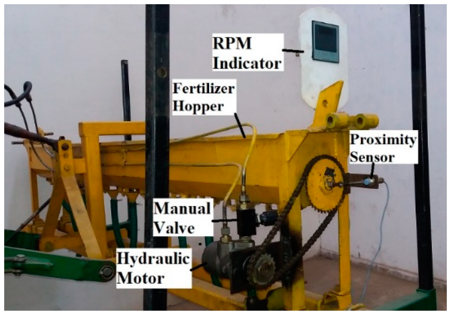
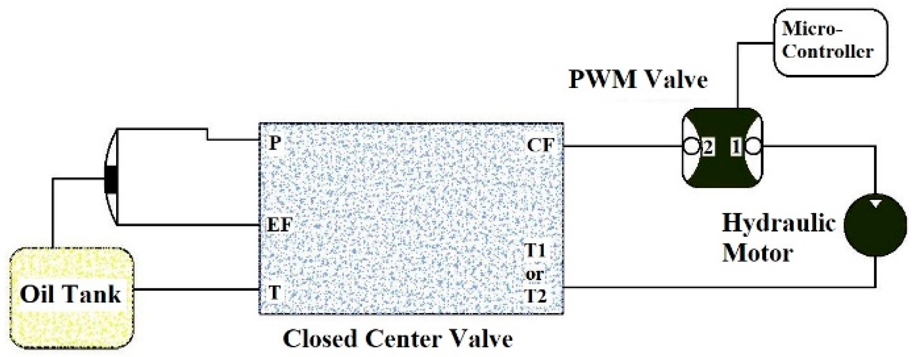
2.5. Hydraulic System

A basic hydraulic system was used for the study i.e., a three-point linkage system used in tractors. There was a requirement to change the speed of the hydraulic motor to be mounted on the shaft of the fluted roller type metering mechanism. This was achieved by passing the command of the microcontroller to the fluted roller shaft in order to vary the shaft speed based on NDVI data. The hydraulic system, which included hydraulic hoses, a hydraulic motor, and a hydraulic valve assembly, was used to control the flow rate.

2.5.1. Hydraulic Fluid Flow System

The hydraulic valve assembly manages the system’s pressure by controlling the hydraulic oil flow rate from the tractor and thus regulating the speed and torque of the hydraulic motor shaft. The speed of the hydraulic motor shaft caused a different rpm of the fluted roller shaft, and in this way, controlled the fertilizer delivery rate from the applicator. The oil provided through the hydraulic pump of the tractor was usually delivered at pressure of 13.78 to 20.68 kPa.
The overall hydraulic flow control system of the variable rate applicator is shown in Figure 3. The hydraulic oil flowed from the oil reservoir of the tractor over the closed center valve via the hydraulic port of the tractor. The oil was then passed through the PWM valve before being transmitted to the hydraulic motor. The reversal oil finally moved back to the oil reservoir after flowing through the hydraulic motor via the closed center valve.

2.5.2. Hydraulic Hoses

The hydraulic hoses used in the system were steel pipes that were precisely seamless, particularly made for hydraulic purposes. The hydraulic valve assembly was linked to the supplier through 15 mm diameter tubes, and the PWM valve was connected to the hydraulic motor through 10 mm diameter tubes. The pipes were interrelated through welding and nipples. The PWM valve was linked to the hydraulic motor through hydraulic hoses.

2.5.3. Hydraulic Motor

The hydraulic motor converted the oil fluid pressure to mechanical load. It varied the speed of the metering mechanism shaft by changing the oil flow rate, which was controlled by the PWM valve of the system. The hydraulic motor was selected for the system by calculating power required to rotate the drive shaft of a fluted roller-metering mechanism in the fertilizer box filled with fertilizer and had a maximum power output of 16.1 kW. It had a maximum shaft speed of 480 rpm and torque ranging from 280 to 370 Nm. The motor transported the flow at pressure limits of 0.69 and 22.48 kPa with a volume flow rate ranging from 9 to 19.8 lit min−1.

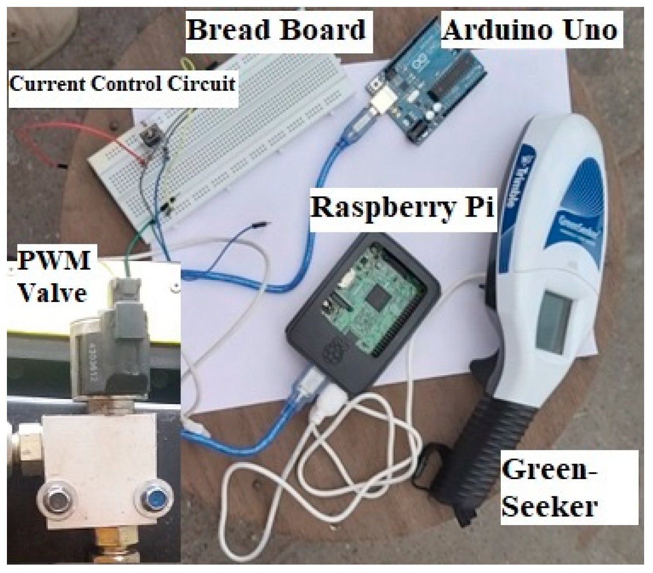
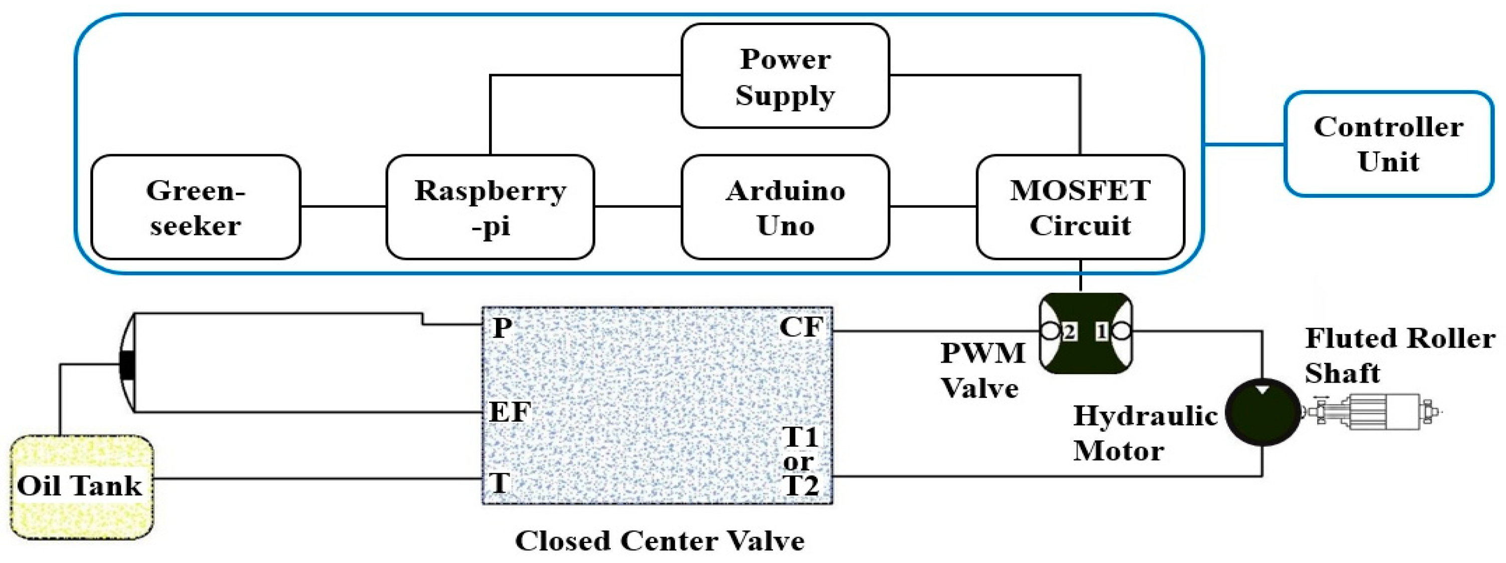
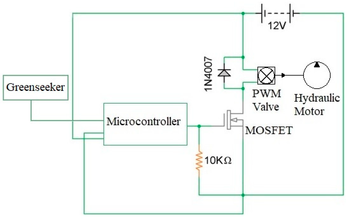
2.6. Development of Controller System

The controller system received a signal from the N sensor (Greenseeker) via a Raspberry Pi microcontroller board. Then, based on the Greenseeker algorithm [23] and PAU’s fertilizer rate recommendation [24], the amount of fertilizer required was identified, and then a signal with 10-bit resolution was sent to the PWM valve by Arduino microcontroller board to control the oil flow rate in the hydraulic system. Through controlling the oil flow rate, the speed of the hydraulic motor was regulated, which resulted in variation in the fluted roller-metering mechanism drive shaft speed. The rotational speed of the fluted roller-metering mechanism drive shaft was proportional to the required rate in order to adopt a suitable signal (10-bit) to the PWM valve. The controller system consisted of a Raspberry Pi microcontroller board (Raspberry Pi 3 B+ BCM2837), Arduino microcontroller board (Arduino Uno ATMega328p), MOSFET (Generic 30 A, 200 V, Irf540N, N-Channel), power supply (a mobile power bank 10,000 mAh 2i), PWM valve (Raven PWM flow control valve), hydraulic system, and the control software (Figure 4).

2.6.1. Control Unit

This part was responsible for receiving data from the Greenseeker, and using it to get the N status of the crop, identify the required rotational speed of the drive shaft, and send a signal to the PWM valve to regulate the oil flow rate. The schematic diagram in Figure 5 shows how the rotational speed of the fluted roller drive shaft is controlled. To achieve the required speed on the hydraulic motor, a PWM valve was used to control the oil flow rate by receiving a signal from the microcontroller after it analyzed the Greenseeker data. Pulse signals were produced by the microcontroller based on the input from the N sensor. Signals were sent to the on/off valve for the oil flow through a MOSFET. MOSFET is a special type of metal oxide semiconductor field effect transistor which was selected for the study to match the current requirements of the valve control circuit.

2.6.2. Software Section/Control Software

The Python and C languages were used as interface programs to regulate the fertilizer rate in real time. Greenseeker data about the status of N were used as a direct input to the Python language, which was used in Raspberry Pi. Afterwards, the data were processed, sending a signal to the PWM valve through Arduino Uno, which was programmed in C language. In the first section, the NDVI data were received as dimensionless values from Greenseeker. The Raspberry Pi received the data, controlled the sensor using a trigger circuit, and sent the data wirelessly to Arduino Uno via Bluetooth. In the second section, data were received in Arduino Uno and translated to the appropriate signal based on a Greenseeker algorithm theory (N application rate in response to NDVI) and fertilizer rate, based on fluted roller-metering mechanism drive shaft rotational speed, in C language. The aim of Arduino Uno software was to give the PWM control signal to the valve via MOSFET to control current supply of the PWM valve of oil flow, which in turn controlled the hydraulic motor speed by regulating the oil flow rate. The software automatically, processed the received data from the sensor and sent a command to the valve to control the oil flow rate in order to eventually control the drive shaft rotational speed.

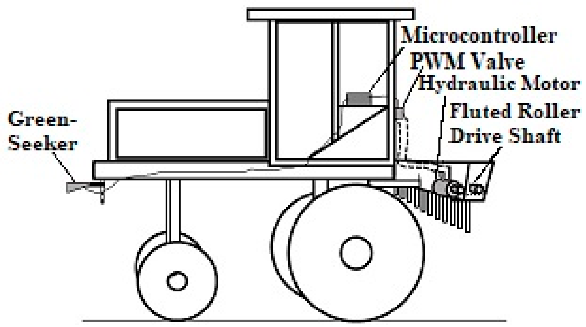
2.7. Integration of Different Systems of the Variable Rate Real-Time Fertilizer Applicator

Mechanical, hydraulic, and sensing systems were integrated to communicate with each other for the development of a variable rate real-time fertilizer applicator. The microcontroller was used as an embedded component to accomplish the required operations and was able to control the PWM valve in order to operate the hydraulic control system routinely without necessitating manual operation. The Greenseeker directly sent NDVI values to the Raspberry Pi 3 board which processed the received data based on an algorithm to extract only the useful values. It then transmitted the data to Arduino Uno, which processed the values and decided which PWM command to send to the valve control circuit based on a coded algorithm. The valve control unit received the PWM command and regulated the current supply to the oil flow valve with the help of a MOSFET accordingly. Varying the current supply to the oil flow valve controlled the opening and closing of the valve, which in turn controlled the hydraulic motor to dispense fertilizer at a variable rate. The integration of different systems developed for the variable rate applicator is shown in Figure 6.
The interface and structure of a set of functional programs for NDVI-based hydraulic motor speed variation were established by taking NDVI data from Greenseeker and sending the appropriate signal to the PWM valve. The mathematical model applied for calculations was built on a group of differential equations of the Greenseeker algorithm theory, machine forward speed, the fertilizer discharged based on the fluted roller drive shaft speed, the PWM valve function, and the distance of Greenseeker from the discharger tubes balance for exact lag time.

2.8. Evaluation of the Variable Rate Real-Time Fertilizer Applicator

2.8.1. Calibration of the Fertilizer Metering Mechanism

Functional testing of the metering mechanism of the applicator was carried out in Dr. S. R. Verma Research Hall, Department of Farm Machinery and Power Engineering of Punjab Agricultural University. As per PAU recommendation [24], total recommended fertilizer for wheat crop is 270 kg ha−1, of which 108 kg ha−1 is to be applied manually at the time of sowing wheat as well as at the first irrigation and the rest (162 kg ha−1) is to be distributed based on crop requirement before the second irrigation. Before installing the microcontroller, a manual regulator valve was installed in the hydraulic system/circuit to calibrate the fertilizer discharge rate at different drive shaft rotational speeds. The applicator lever, which manually regulated the rate of fertilizer, was fixed in a constant position of maximum N rate recommended by PAU for wheat crop (162 kg ha−1) and at a maximum rotational speed of fluted roller-metering mechanism drive shaft (40 rpm). This was done in order to evaluate the fertilizer rate for the four different drive shaft rotational speeds and also to evaluate the variation among the discharger tubes. Rotational speeds of 10, 20, 30, and 40 rpm were chosen for the fluted roller-metering mechanism drive shaft and speed of the tractor was selected to be 3 km h−1 [25]. In each rotational speed, and with three replications, fertilizer was collected in poly bags placed under the discharge tubes.

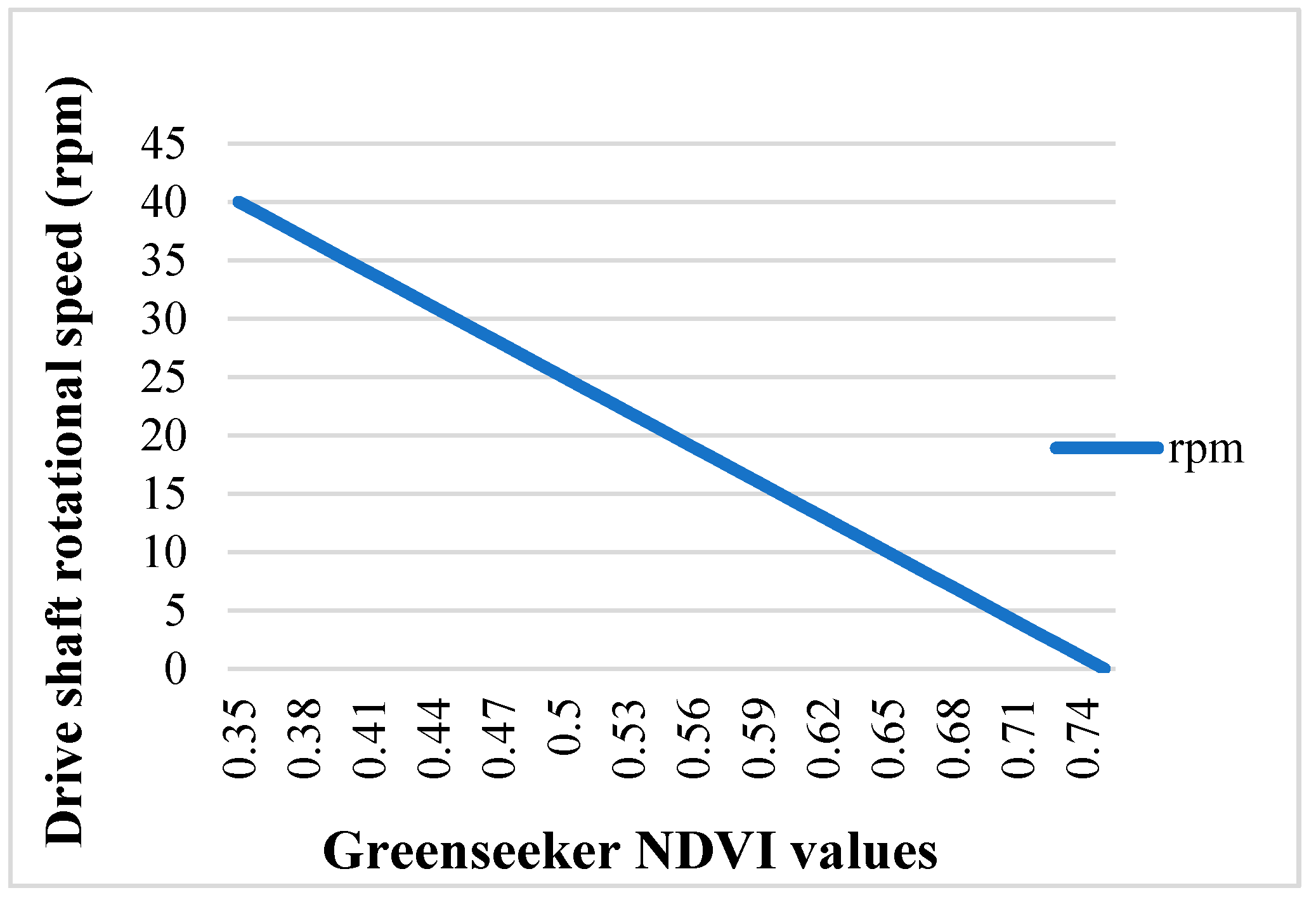
2.8.2. Variation in Rotational Speed of Metering Mechanism Drive Shaft with Corresponding Crop NDVI Sensed by Greenseeker

Variation in rotational speed of the drive shaft of the metering mechanism and NDVI of the crop are shown in Figure 7. Drive shaft rotational speed was varied with respect to NDVI provided by Greenseeker based on Greenseeker algorithm theory, which was discussed in the N sensor section [23]. Rotational speed of the drive shaft of the metering mechanism was used to change the rpm from 0 to 40 when NDVI was changed from 0.75 to 0.35. This means that when NDVI is higher (Maximum NDVI is 0.75), the crop is healthier and less fertilizer (Minimum 0 rpm) is needed by the crop. When NDVI is lower, (Minimum NDVI is 0.35), the crop requires more fertilizer (Maximum 40 rpm).

2.8.3. Amount of N Fertilizer Applied by Applicator

The amount of N fertilizer applied by the variable rate real-time fertilizer applicator was collected by placing poly bags under the fertilizer discharge tubes by moving the applicator from four plots representing different levels of nitrogen. An applicator was used to pass three replications, which each had four plots. Therefore, the experiment was conducted with 12 plots.

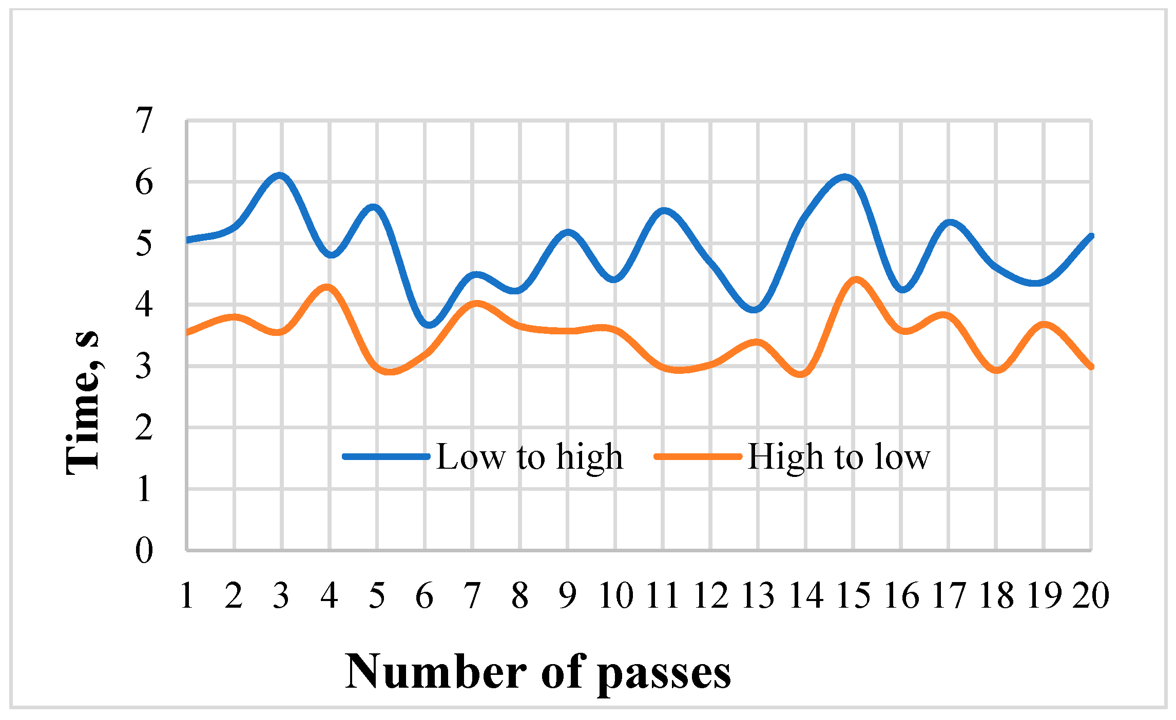
2.8.4. Evaluating the Real-Time Variable Fertilizer Applicator Response Time

To identify the applicator response time, data from two different crop samples with two different NDVI values, representing required fertilizer rates of 40.5 and 162 kg ha−1, were used to change the Greenseeker’s NDVI values. Then the microcontroller received the Greenseeker’s NDVI values to send a command signal to the PWM to vary the fluted roller drive shaft rotational speed from low to high and high to low (10 rpm to 40 rpm). As mentioned above, for low to high transition, a crop with higher greenery with a NDVI representing 10 rpm was used. Then, after the rotational speed of the drive shaft became constant at 10 rpm, a crop with lower NDVI, representing 40 rpm of drive shaft rotational speed was placed under the Greenseeker to get the corresponding NDVI. The timer of a stopwatch was started at the initiation of the sensing while the rpm indicator simultaneously checked the change in rotational speed to display 40 rpm and stopped the timer. The inverse of this method was applied to obtain the response time for high to low transition.

2.8.5. Field Evaluation of the Real-Time Variable Rate Fertilizer Applicator

The applicator was evaluated at the Research Farm of the Department of Farm Machinery and Power Engineering, Punjab Agricultural University, Ludhiana to assess the discharged fertilizer.

2.8.6. Plan of Experiment on Test Evaluation of Variable Rate Fertilizer Applicator

Different parameters selected for the study included N level (0, 90, 180, and 270 kg ha−1), which was the independent variable as well as response time and amount of applied N fertilizer, which were the two dependent variables.

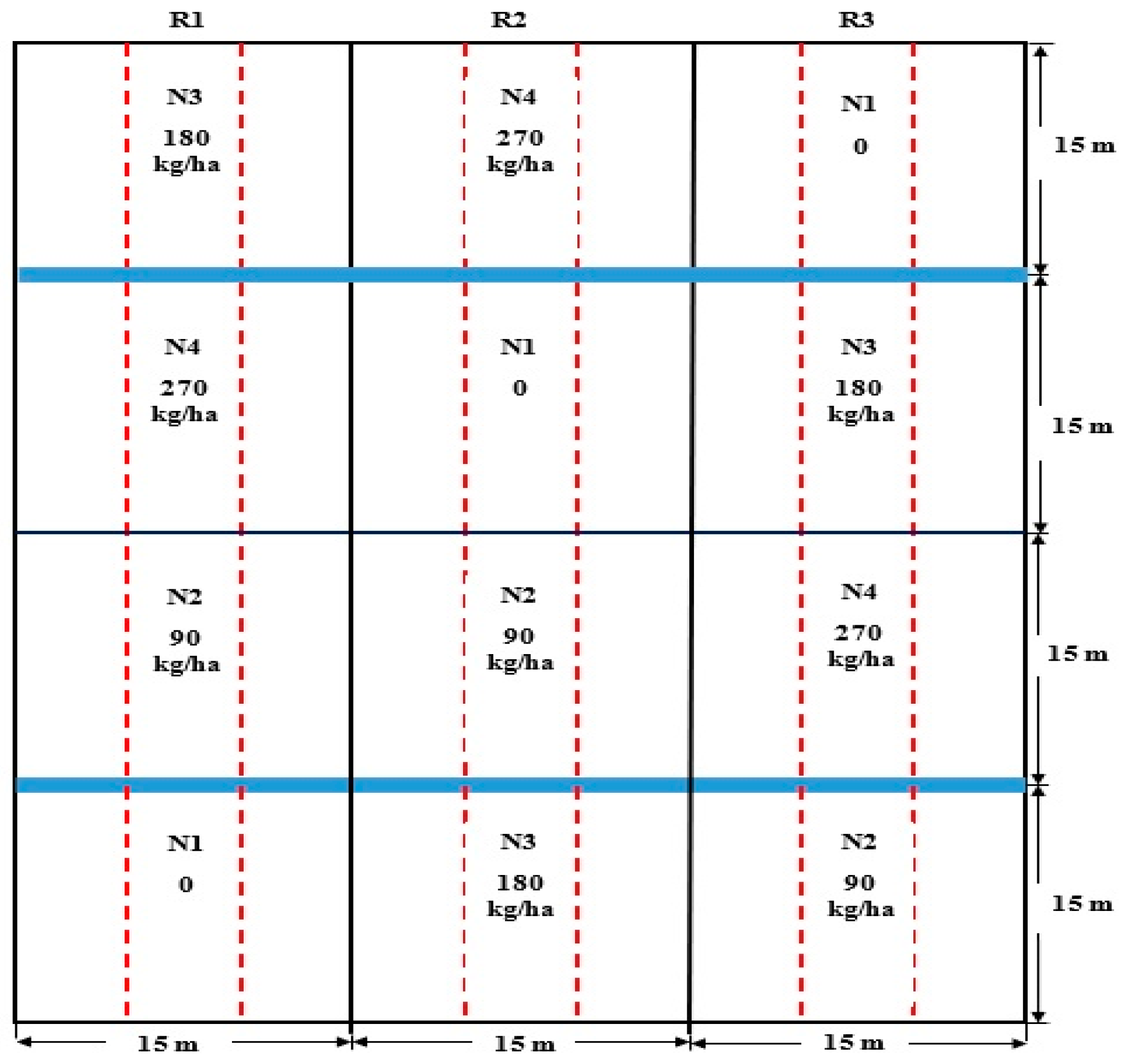
2.8.7. Experimental Field Layout

The developed applicator was field-evaluated during the 2019–2020 wheat season (November to March) at a research farm of PAU; 30.90° N, 75.81° E with an average elevation of 244 m; loamy soil with pH 7.1, organic C [26] 2.9 g kg−1, 0.5 M NaHCO3 extractable P [27] 5.1 mg kg−1, and NH4OAc extractable K [28] 52 mg kg−1 and an area of 60 × 45 m2. The field experiment was laid out in a randomized complete block design as shown in Figure 8 and was conducted with wheat crop. Treatments, namely different N levels, were selected for the study. There were three replications for each treatment condition.

2.8.8. Nitrogen Level

Research field was divided into three replications with three paths for the applicator and each replication was divided into four plots (15 × 15 m2). Each plot with each replication was randomly assigned one of the four rates of N fertilizer (0, 90, 180, and 270 kg ha−1) and the set amount of N fertilizer for each level was uniformly applied manually in all of them. Initially, fertilizer was uniformly and manually applied in all of the plots in order to produce manual variation in the research field with the intention to evaluate the variable rate fertilizer applicator in a field with varied fertilizer conditions.

3. Results and Discussion

3.1. Fertilizer Metering Mechanism Calibration

Results revealed that, for a fixed tractor speed, the fertilizer rate varied with respect to the fluted roller-metering mechanism drive shaft rotational speed. The fertilizer rate linearly increased and decreased with corresponding increment and decrement of drive shaft rotational speed for a fixed fluted roller drive shaft. Coefficients of variation (CV) of discharged fertilizer at 11 dispensers were low ranging from 2.34 to 5.1%. This aligns with past research that has proven that the fluted roller type mechanism has lesser variation in fertilizer rate applied as compared to the spinner disc type, which has a CV ranging from 20.0–50.0% [29].

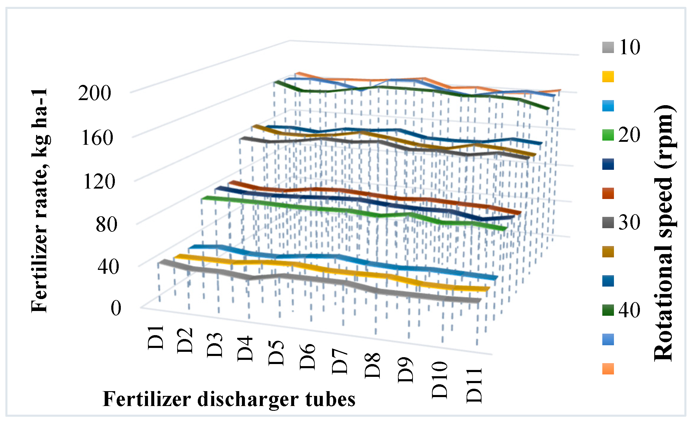
3.2. Effect of Fluted Roller Drive Shaft Rotational Speed on Fertilizer Rate and Variation among Fertilizer Discharger Tubes

The effect of fluted roller drive shaft rotational speed on fertilizer rate and variation among fertilizer discharger tubes is shown in Figure 9. The result fulfilled the requirement of a variable rate applicator developed to change the fertilizer rate with the change in the drive shaft rotational speed of the fluted roller-metering mechanism. Fertilizer rate at 10 rpm was minimum i.e., 40.17 kg ha−1 and was maximum 162.74 kg ha−1 at 40 rpm of the drive shaft rotational speed. The variation in discharged fertilizer rate at different outlets decreased with the increase of the fluted roller drive shaft speed. This may be due to the smooth flow of fertilizer at lower speeds with more agitation provided at higher speed of the drive shaft of the metering mechanism.

3.3. Response Time

Measurements were carried out to find out response time from the N-sensor to the corresponding fluted roller drive shaft rotational speed based on change in different NDVI values in order to test the efficiency of on-the-go fertilizer adjustment. Response time of the applicator from the sensing unit to change in the rotational speed for a low-to-high-rate change (from 40.17 to 162.74 kg ha−1) at 3 km ha−1 and for high-to-low-rate change (from 162.74 to 40.17 kg ha−1) at 3 km h−1 is shown in Figure 10.
The control system was assessed against its response to transition time during the variable rate application trials where there was a requirement to change the fertilizer rate. The data showed that the system response time of the control system to step change adjustments (the transition period from 40.17 to 162.74 kg ha−1) was within the range of 3.49 to 4.90 s for both high-to low-rate and low-to-high-rate. Since the speed of the tractor was 3 km h−1, by mounting the Greenseeker somewhere suitable at the front of the tractor, the lag time for dispensing fertilizer at the place of Greenseeker data collection by calculation was found to be 4.8 s. This response time was suitable for the applicator as compared to Jafari et al. [8] with a response time of 7.2 and 5.2 s, and Tola et al. [7] with a response time of 0.95 and 1.9 s.

3.4. Application of Fertilizer 60 Days after Sowing (60 DAS), before Second Irrigation of Wheat Crop Using Variable Rate Applicator

Fertilizer was applied by using a developed variable rate applicator before second irrigation of the wheat crop at 60 DAS. NDVI, shaft speed (rpm), and fertilizer rate applied at different N levels in wheat crop before second irrigation (60 DAS) are shown in Table 1. When fertilizer rate is increased from N1 to N4, NDVI increases from 0.56 to 0.78. Hence, shaft speed is decreased from 20 to 0 rpm to apply fertilizer at a rate of 78.36 to 0.00 kg ha−1.
The total amount of fertilizer applied by the variable rate applicator was 0 kg ha−1 at N4, which reveals that since this area had already received the maximum recommended fertilizer, the applicator did not apply extra fertilizer. Similarly, in N1, N2, and N3 the total amounts used were 78.36, 48.83, and 24.19 kg ha−1 respectively. These results indicate that the applicator applies fertilizer based on N fertilizer available in the crop and requirements of the crop and as compared to map-based variable rate fertilizer developed by Iida et al. [15] was found to be suitable for farmers’ use, in which their results showed that fertilizer used in the variability part was 12.8% less.

4. Conclusions

A real-time variable rate fertilizer applicator was designed and developed to vary the N fertilizer rate using a fluted roller-metering mechanism type in real time. Compared to previous studies, such as those on map-based variable rate technology, the present study set out to design a more cost-effective, sensor-based fertilizer application method [15]. Hence, the Greenseeker handheld sensor (Trimble Inc., Sunnyvale, CA, USA) was selected for use in this study since it is low cost, canopy-based, and easy to mount on a tractor, making it more economically feasible and affordable for a wider range of farmers, especially for farmers in developing countries. The fluted roller feeding system was designed for fertilizer applicator development because the positive feeding system results in proper changes of the dispensed amount via regulation of the speed of the fluted roller. The applicator consisted of: (a) a Greenseeker, (b) a microcontroller using Arduino Uno and Raspberry Pi board, (c) a PWM valve, (d) a hydraulic circuit, (e) a hydraulic motor, (f) an indicator for sensing the rotational speed of the fluted roller type metering mechanism shaft, and (g) a fluted roller type metering mechanism. The system was evaluated at two different N fertilizer application rates. When the fluted roller drive shaft rotational speeds were 10 and 40 rpm, the fertilizer rates were 40.17 and 162.74 kg ha−1 respectively. When NDVI was increased from 0.35 to 0.75, the speed of the fluted roller drive shaft decreased from 40 to 0 rpm. The response time of the control system to apply fertilizer in the field fell within the range of 3.49 to 4.90 s while the tractor forward speed was 3 km h−1. The CV of discharged fertilizer at different outlets was lesser, ranging from 2.34 to 5.1% in comparison to previous research with the spinner disc type, which typically has a CV ranging from 20.0–50.0% [29]. This implies that the fluted roller mechanism uniformly applied the right amount of fertilizer required by each specific area. The mechanism designed in the present study performed well compared to past research on variable rate controllers for seeding [8]. The applicator applied N fertilizer with respect to different N levels, as well as based on N fertilizer available in the crop and its requirements. One Greenseeker was used in the study, hence maximum sensing width was 50 cm and fertilizer application width was 220 cm. Future studies should be conducted using several Greenseekers to improve accuracy of fertilizer application. It would be a good idea to collaborate this sensor-based applicator with the available map-based one [15] to achieve more accuracy to apply precise amount of fertilizer in the field based on crop needs.

Author Contributions

Conceptualization, H.M. and M.S.; methodology, H.M., M.S., V.B., O.P.G. and R.S.; software, H.M., R.S. and O.P.G.; formal analysis, H.M. and M.S.; investigation, H.M. and M.S.; resources, H.M., M.S. and V.B.; data curation, H.M. and M.S.; writing—original draft preparation, H.M.; writing—review and editing, H.M., M.S., V.B., O.P.G. and R.S. All authors have read and agreed to the published version of the manuscript.

Funding

This study was conducted under research at Punjab Agricultural University, Ludhiana (India). DST funded project under scheme CSS-42 operational at Punjab Agricultural University.

Institutional Review Board Statement

Not applicable.

Informed Consent Statement

Not applicable.

Data Availability Statement

Not applicable.

Acknowledgments

The authors duly acknowledge the help received from the Ministry of Science, Research and Technology of Iran, the Agricultural Ministry of Iran, The Indian Council of Agricultural Research (ICAR), the Indian Council for Cultural Relations (ICCR), the Department of Science and Technology, Ministry of Science and Technology of India, and the Department of Farm Machinery & Power Engineering, college of Agricultural Engineering and Technology, Punjab Agricultural University (PAU) Ludhiana during the study.

Conflicts of Interest

The authors declare that they have no conflict of interest.

References

  1. Department of Agriculture, Cooperation and Farmers’ Welfare; Ministry of Agriculture & Farmers’ Welfare; Government of India. Report of Committee on Doubling Farmers’ Income. 2017. Available online: http://agricoop.nic.in/doubling-farmers (accessed on 17 September 2018).
  2. Food and Agriculture Organization of the United Nations. World Fertilizer Trends and Outlook to 2020, pp. 1–53. Available online: http://www.fao.org/3/i6895e/i6895e.pdf (accessed on 3 May 2020).
  3. Burns, I.G. The effects of continuity of early nitrogen nutrition on growth and development of Lactuca sativa. In Plant Nutrition—Physiology and Applications; Springer: Dordrecht, The Netherlands, 1990; pp. 545–549. [Google Scholar]
  4. Larson, W.E.; Robert, P.C.; Rust, R.H. Proceedings of soil specific crop managementa workshop on research and development issues. In Proceedings of the Workshop, Soil Specific Crop Management 1th, (No. LC-0088), Minneapolis, MN, USA, 14–16 April 1992; Department of Soil Science, Minnesota Extension Service University of Minnesota: St. Paul, MN, USA, 1993. [Google Scholar]
  5. Bahri, A. Modulating Wheat Seeding Rate for Site Specific Crop Management. Ph.D. Thesis, University of Nebraska, Lincoln, NE, USA, 1996. [Google Scholar]
  6. Maleki, M.R.; Mouazen, A.M.; De Ketelaere, B.; Ramon, H.; De Baerdemaeker, J. On-the-go variable-rate phosphorus fertilisation based on a visible and near-infrared soil sensor. Biosyst. Eng. 2008, 99, 35–46. [Google Scholar] [CrossRef]
  7. Tola, E.; Kataoka, T.; Burce, M.; Okamoto, H.; Hata, S. Granular fertiliser application rate control system with integrated output volume measurement. Biosyst. Eng. 2008, 101, 411–416. [Google Scholar] [CrossRef]
  8. Jafari, M.; Hemmat, A.; Sadeghi, M. Development and performance assessment of a DC electric variable-rate controller for use on grain drills. Comput. Electron. Agric. 2010, 73, 56–65. [Google Scholar] [CrossRef]
  9. Anderson, N.W.; Homburg, D.S. Application Equipment for Site-Specific Management. In The State of Site Specific Management for Agriculture; Pierce, F.J., Sadler, E.J., Eds.; American Society of Agronomy: Madison, WI, USA, 1997; pp. 245–281. [Google Scholar]
  10. Kim, Y.J.; Kim, H.J.; Ryu, K.H.; Rhee, J.Y. Fertiliser application performance of a variable-rate pneumatic granular applicator for rice production. Biosyst. Eng. 2008, 100, 498–510. [Google Scholar] [CrossRef]
  11. Yu, J.H.; Kim, Y.J.; Yu, K.H. Development of a controller for variable-rate application of granular fertilizer in paddy farming. In ASAE Annual Meeting, Oregon, 2006; American Society of Agricultural and Biological Engineers: Saint Joseph, MI, USA, 2006. [Google Scholar]
  12. Huffmeyer, E.H. Inclinometer-Controlled Apparatus for Varying the Rate of Seed Population. U.S. Patent 6,640,733, 4 November 2003. [Google Scholar]
  13. Drummond, P.E.; Christy, C.; Lund, E.; Kejr Inc. Variable Rate Drive. U.S. Patent Application 09/870,174, 5 December 2002. [Google Scholar]
  14. Landphair, D.K.; Myers, C.A. Variable Speed Drive for Agricultural Seeding Machines. U.S. Patent 7,273,016, 25 September 2007. [Google Scholar]
  15. Iida, M.; Umeda, M.; Radite, P.A.S. Variable rate fertilizer applicator for paddy field. In ASAE Annual Meeting, California, 2001; American Society of Agricultural and Biological Engineers: Saint Joseph, MI, USA, 2001. [Google Scholar]
  16. Talha, Z.; Tola, E.; Al-Gaadi, K.A.; Kheiralla, A.F. Pneumatic system for granular fertilizer flow rate control. Middle East J. Sci. Res. 2011, 8, 688–693. [Google Scholar]
  17. Koundal, A.; Singh, M.; Sharma, A.; Mishra, P.K.; Sharma, K. Development and evaluation of an experimental machine for Variable Rate Application of granular fertilizers. In Proceedings of the Sixth IEEE International Conference on Sensing Technology, Kolkata, India, 18–21 December 2012. [Google Scholar]
  18. Benjamin, E.; Krishnan, D.A.; Kavitha, R. Development of Fertilizer Broadcaster with Electronically Controlled Fluted Roller Metering Mechanism for Paddy Crop. Int. J. Curr. Microbiol. Appl. Sci. 2019, 8, 2694–2703. [Google Scholar] [CrossRef]
  19. Van Loon, J.; Speratti, A.B.; Gabarra, L.; Govaerts, B. Precision for smallholder farmers: A small-scale-tailored variable rate fertilizer application kit. Agriculture 2018, 8, 48. [Google Scholar] [CrossRef] [Green Version]
  20. Ali, A.M.; Thind, H.S. A framework for refining nitrogen management in dry direct-seeded rice using GreenSeeker™ optical sensor. Comput. Electron. Agric. 2010, 110, 114–120. [Google Scholar] [CrossRef]
  21. Quebrajo, L.; Pérez-Ruiz, M.; Rodriguez-Lizana, A.; Agüera, J. An approach to precise nitrogen management using hand-held crop sensor measurements and winter wheat yield mapping in a mediterranean environment. Sensors 2015, 15, 5504–5517. [Google Scholar] [CrossRef] [PubMed] [Green Version]
  22. Yao, Y.; Miao, Y.; Huang, S.; Gao, L.; Ma, X.; Zhao, G.; Jiang, R.; Chen, X.; Zhang, F.; Yu, K.; et al. Active canopy sensor-based precision N management strategy for rice. Agron. Sustain. Dev. 2012, 32, 925–933. [Google Scholar] [CrossRef] [Green Version]
  23. Cornell University. Nutrient Management Spear Program, Agronomy Fact Sheet 84: Crop Vigor Sensing for Variable-Rate Nitrogen. Available online: http://nmsp.cals.cornell.edu/guidelines/factsheets.html (accessed on 17 December 2019).
  24. Package of Practices for the Crops of Punjab. Rabi 2019–2020. Available online: https://www.pau.edu/content/pf/pp_rabi.pdf (accessed on 18 November 2019).
  25. Shearer, S.A.; Fulton, J.P.; Veal, M.W.; Stombaugh, T.S. Procedures for Evaluating Variable-Rate Granular Material Application Accuracy; ASAE PM-54 Draft Standard: Saint Joseph, MI, USA, 2005. [Google Scholar]
  26. Walkley, A.; Black, I.A. An examination of the Degtjareff method for determining soil organic matter, and a proposed modification of the chromic acid titration method. Soil Sci. 1934, 37, 29–38. [Google Scholar] [CrossRef]
  27. Olsen, S.R. Estimation of Available Phosphorus in Soils by Extraction with Sodium Bicarbonate; US Department of Agriculture: Washington, DC, USA, 1954; pp. 1–19.
  28. Pratt, P.F.P. Methods of Soil Analysis: Part 2 Chemical and Microbiological Properties. Am. Soc. Agron. Inc. 1965, 9, 1022–1030. [Google Scholar]
  29. Fulton, J.P.; Shearer, S.A.; Chabra, G.; Higgins, S.F. Performance assessment and model development of a variable–rate, spinner–Disc fertilizer applicator. Trans. ASAE 2001, 44, 1071–1081. [Google Scholar] [CrossRef]
Figure 1. A conceptual sketch of the mechanism.
Sustainability 13 08694 g001
Figure 2. Variable rate fertilizer applicator.
Sustainability 13 08694 g002
Figure 3. Hydraulic flow control system of the variable rate applicator.
Sustainability 13 08694 g003
Figure 4. Different components of the controller system, receiving Greenseeker data and sending it to the PWM valve.
Sustainability 13 08694 g004
Figure 5. Control unit circuit.
Sustainability 13 08694 g005
Figure 6. Integration of different systems of variable rate real-time fertilizer applicator.
Sustainability 13 08694 g006
Figure 7. Drive shaft rotational speed (rpm) with respect to NDVI of Greenseeker.
Sustainability 13 08694 g007
Figure 8. Experimental field layout (red dotted and blue lines represented divisions for different paths and irrigation channels, respectively).
Sustainability 13 08694 g008
Figure 9. Effect of fluted roller drive shaft rotational speed on fertilizer rate and variation among fertilizer discharging tubes.
Sustainability 13 08694 g009
Figure 10. Response time of applicator from sensing to varying the rotational speed for a low-to-high-rate change (from 40.17 to 162.74 kg ha−1) at 3 km h−1 and for high-to-low-rate change (from 162.74 to 40.17 kg ha−1) at 3 km h−1.
Sustainability 13 08694 g010
Table 1. NDVI, drive shaft rotational speed (rpm), and fertilizer rate applied by applicator at different N levels in wheat crop before second irrigation (60 DAS).
N Levels (kg ha−1)NDVI ValuesDrive Shaft Rotational Speed (rpm)Fertilizer Rate (kg ha−1)
N1 = 00.562078.36
N2 = 900.631248.83
N3 = 1800.69624.19
N4 = 2700.7800
Publisher’s Note: MDPI stays neutral with regard to jurisdictional claims in published maps and institutional affiliations.

