
Shipboard Data Compression Method for Sustainable Real-Time Maritime Communication in Remote Voyage Monitoring of Autonomous Ships †


Abstract
:1. Introduction
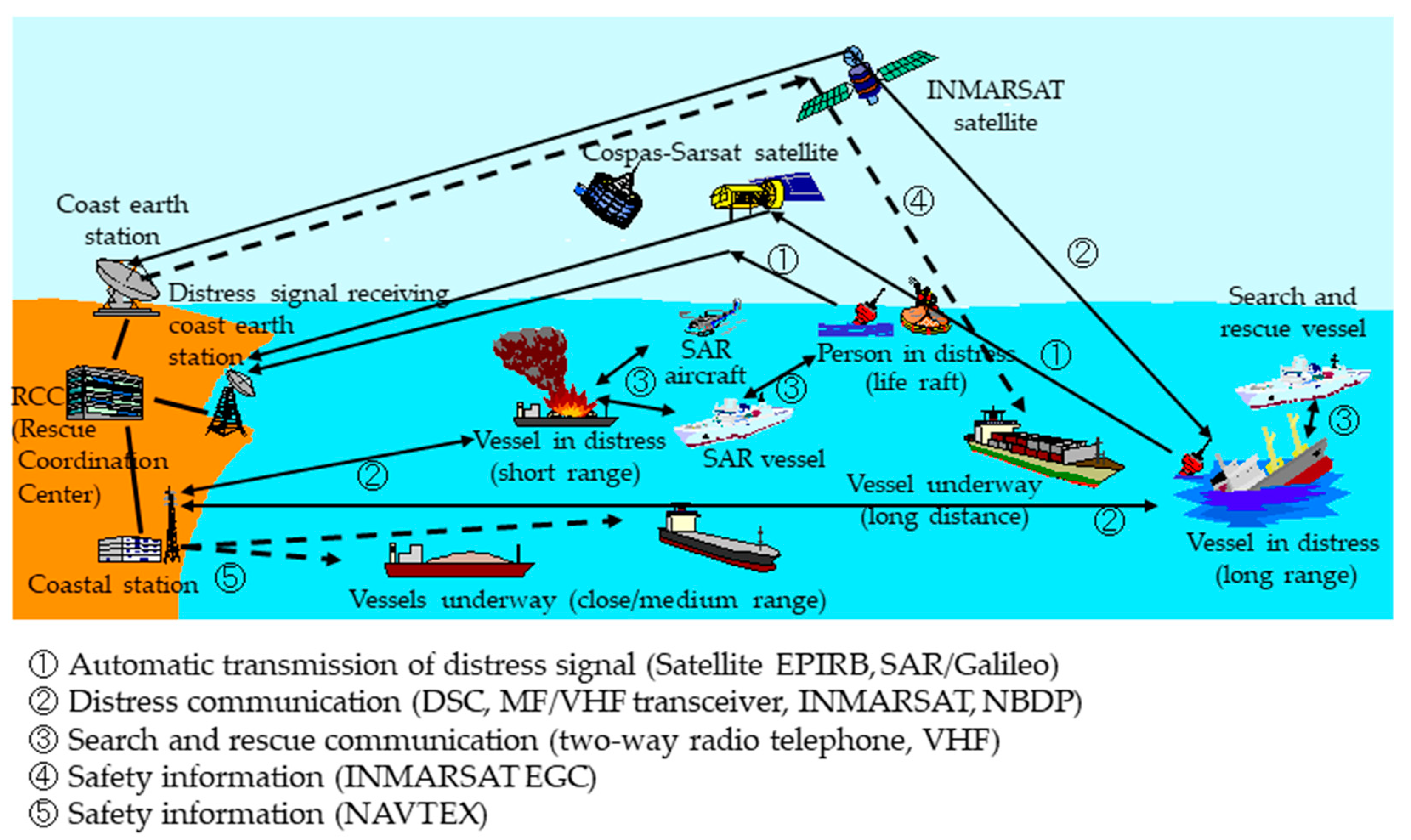
2. Maritime Communications Systems
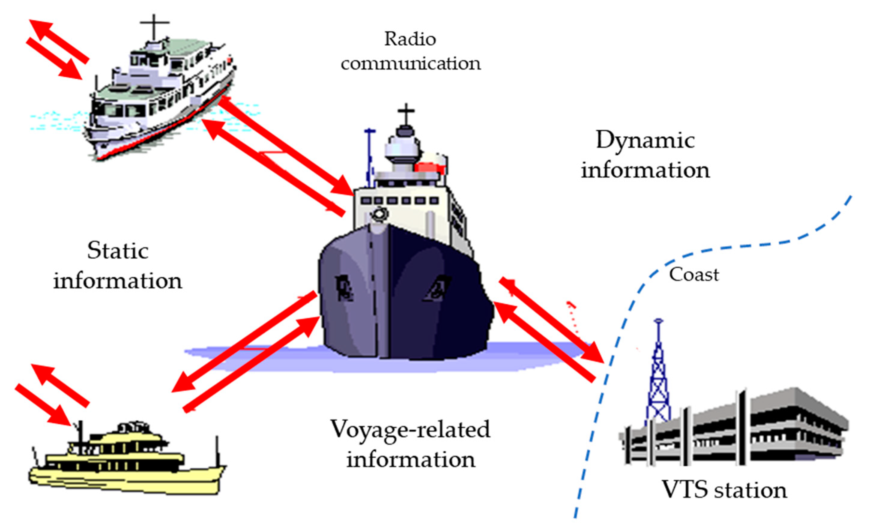
2.1. Overview of Maritime Communications
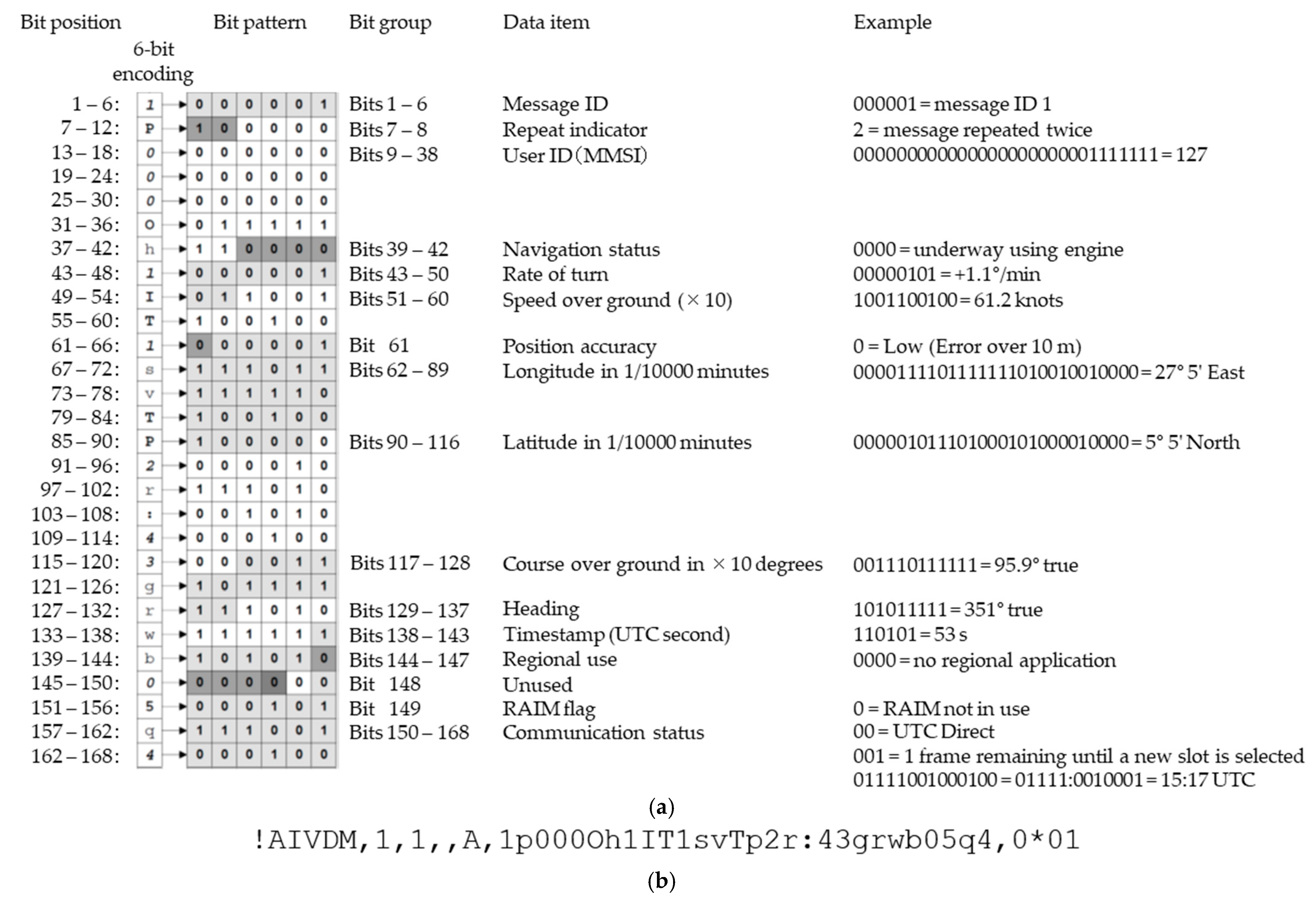
2.2. Automatic Identification System (AIS)
3. Materials and Methods
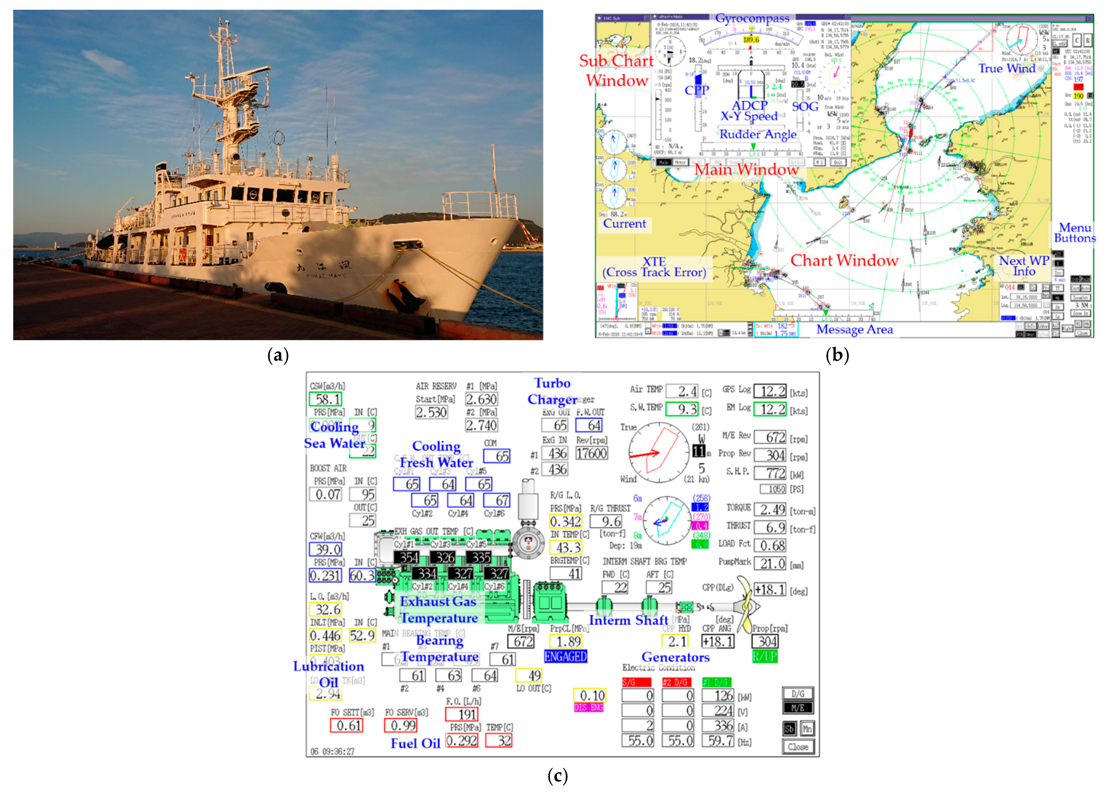
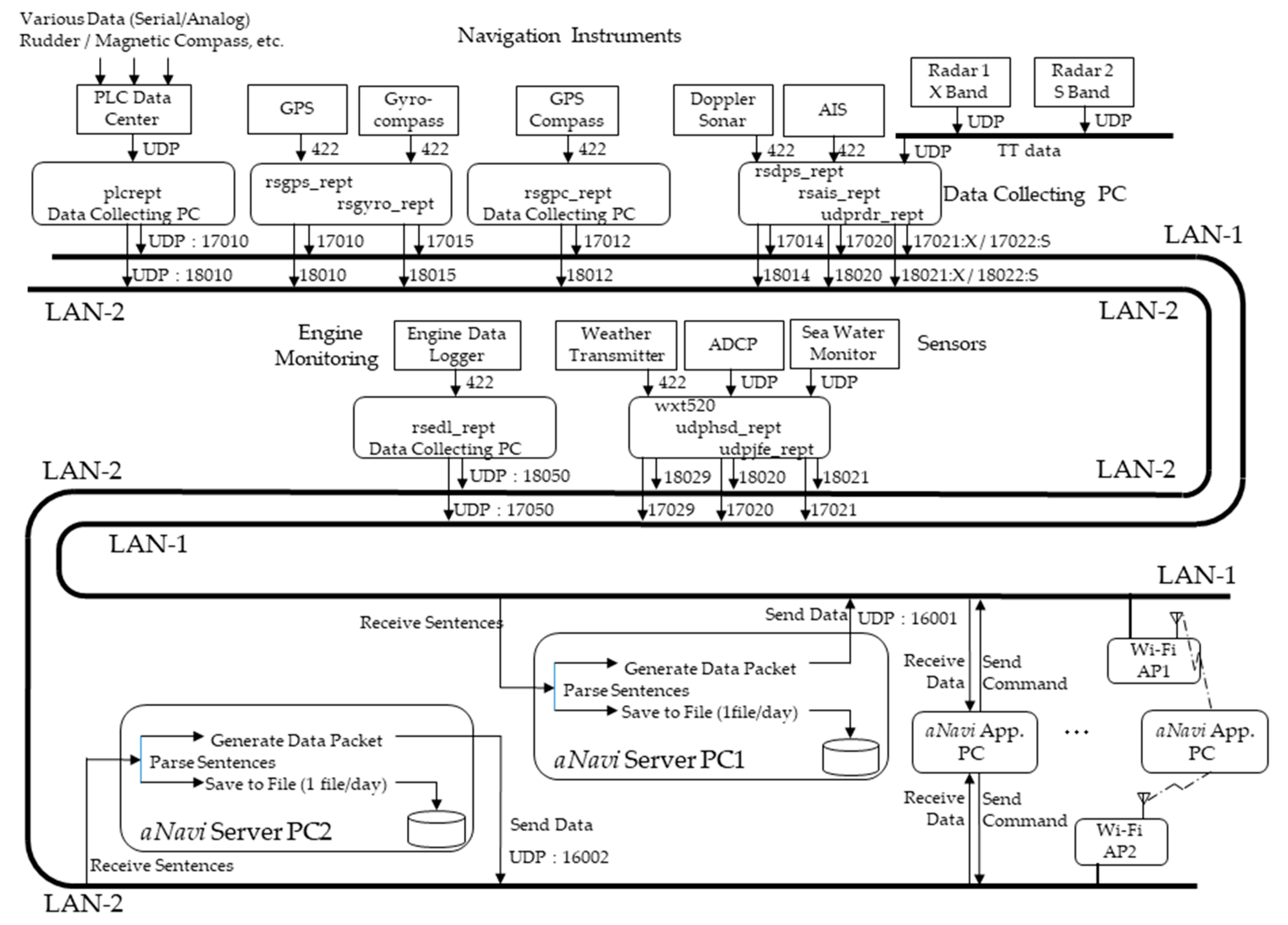
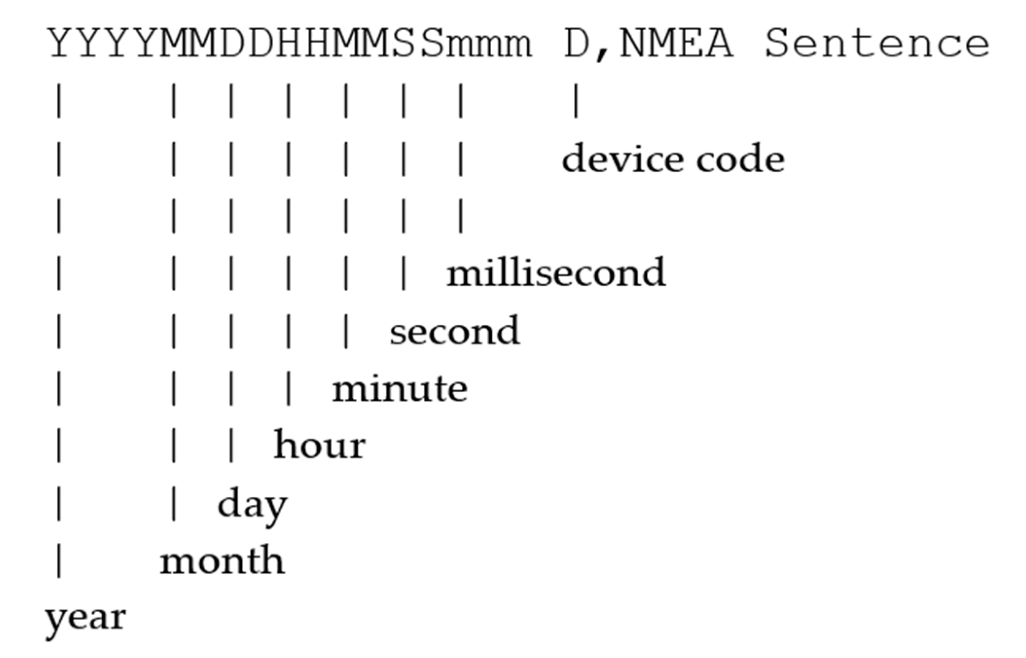
3.1. Shipboard Data Acquisition
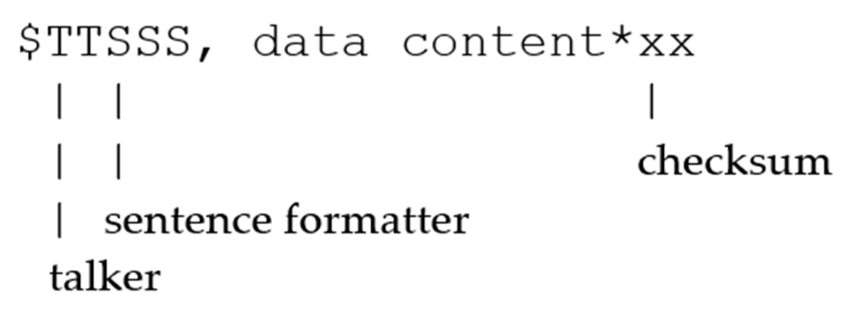
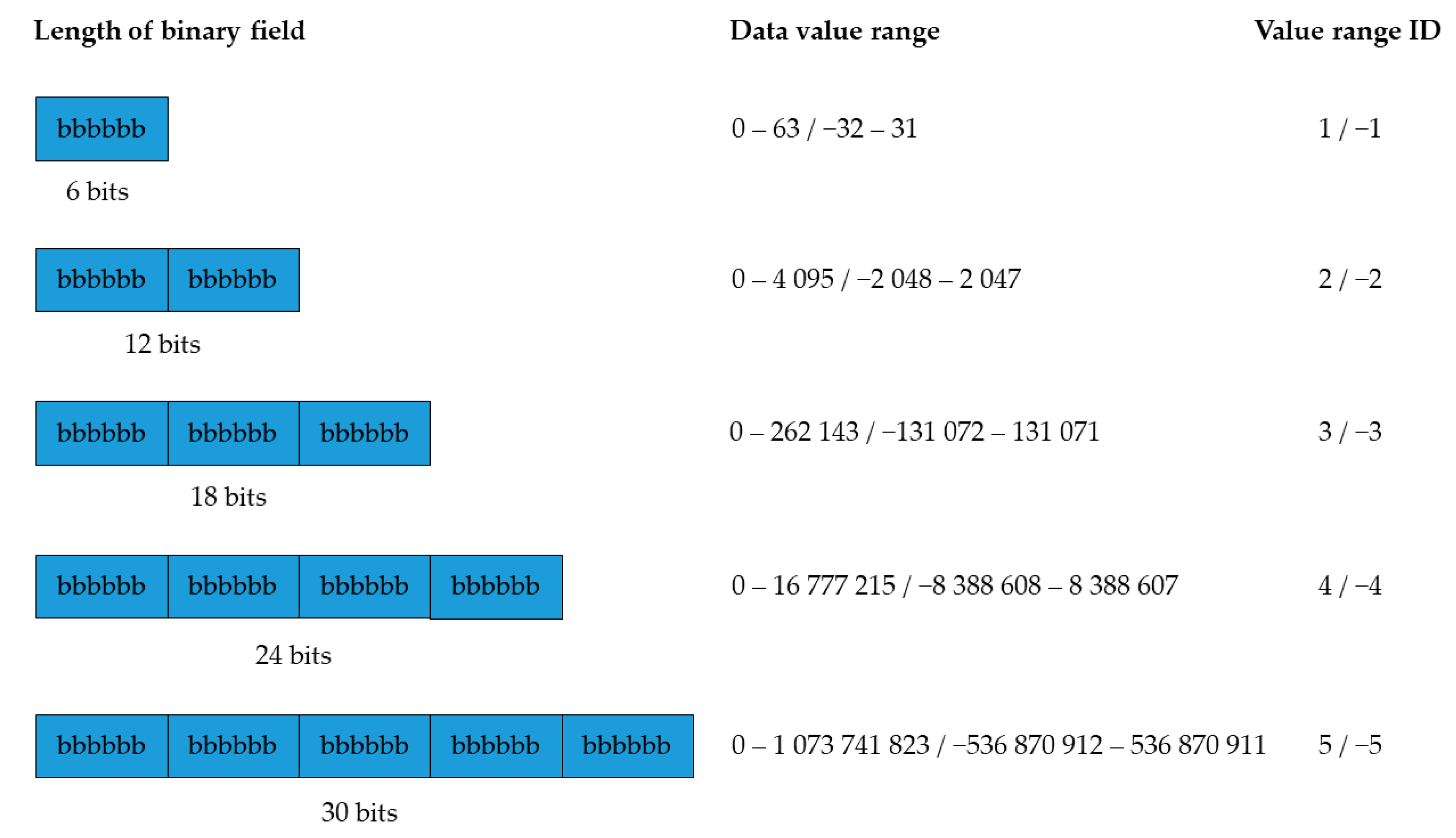
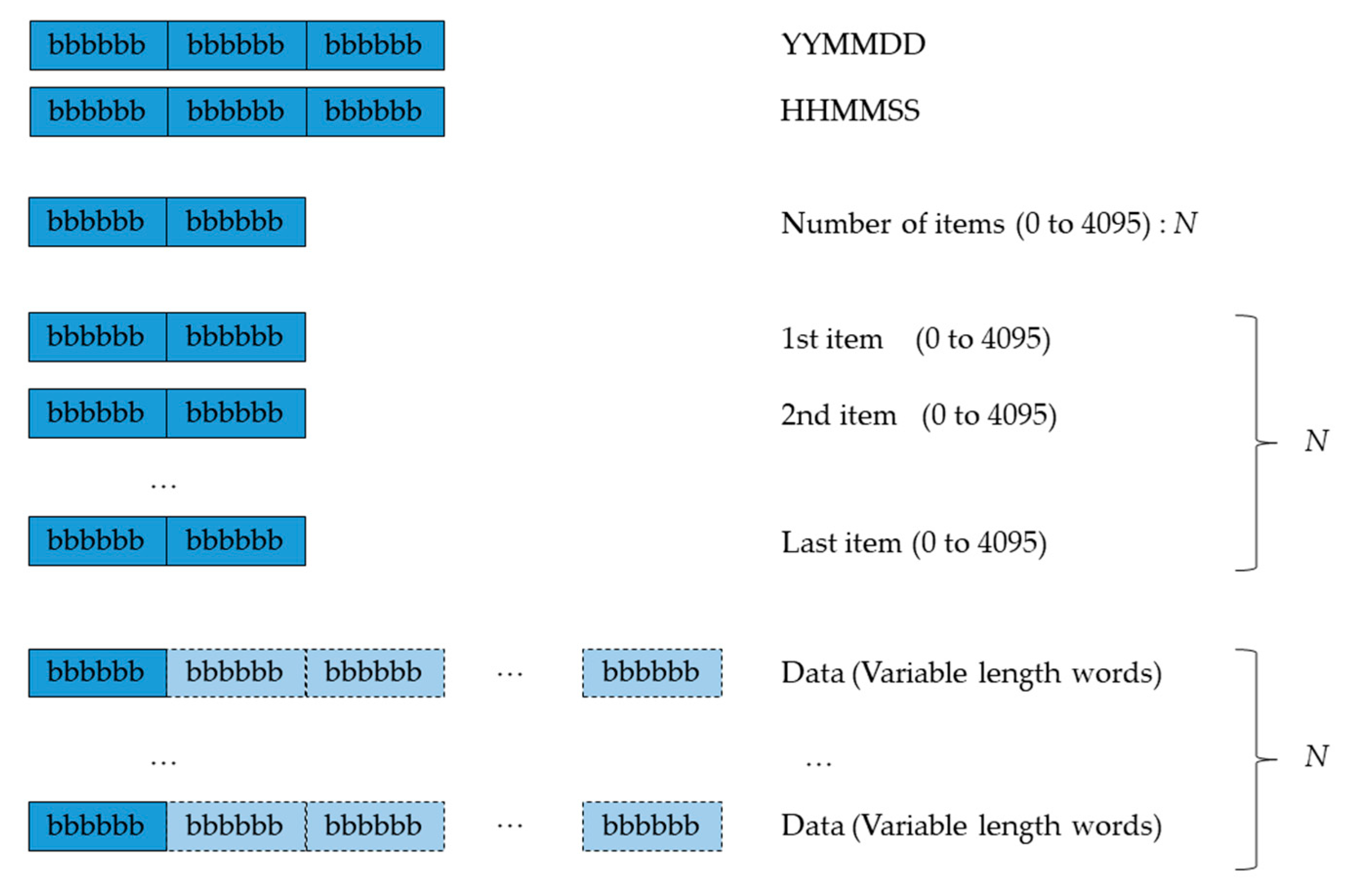
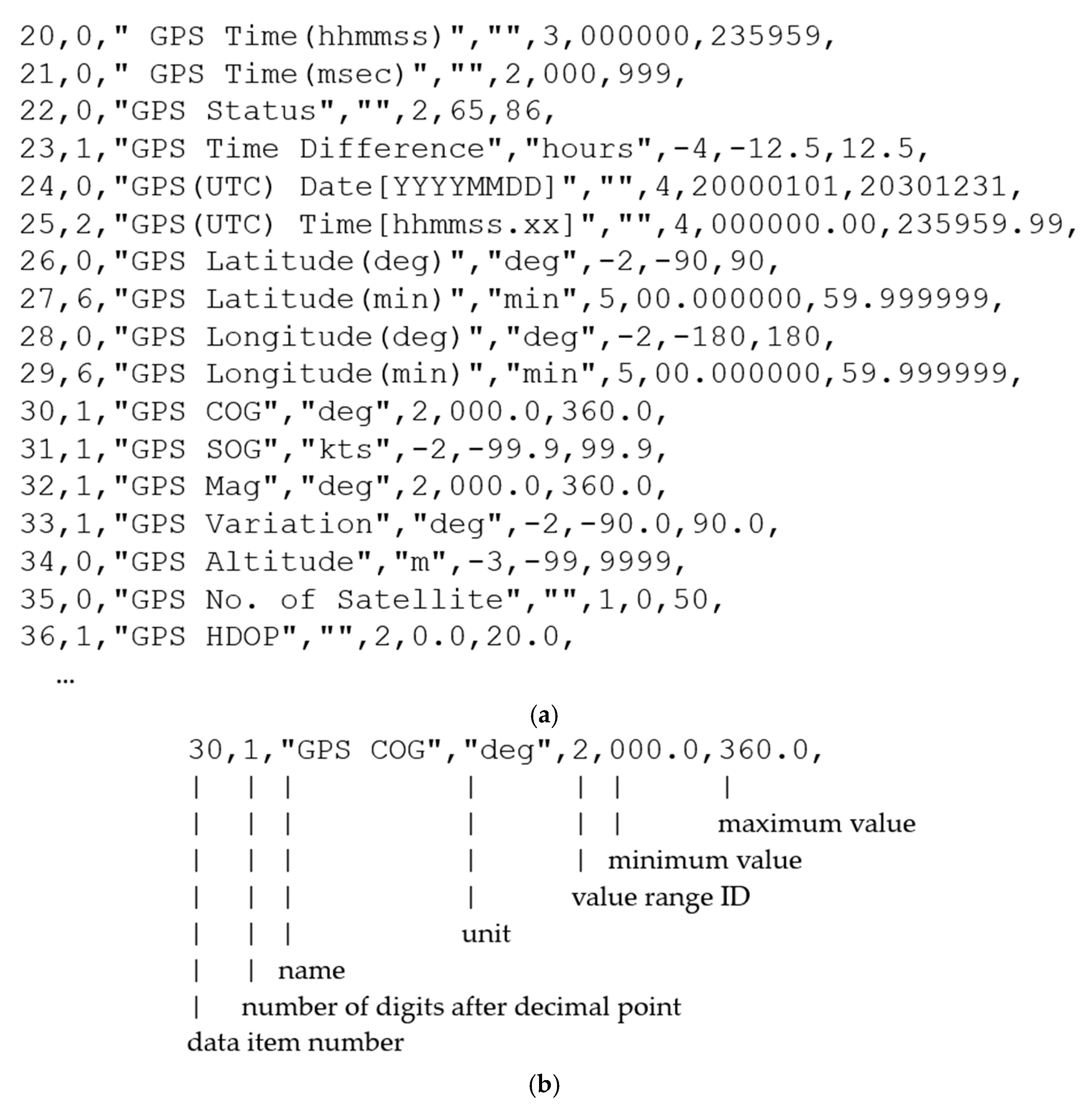
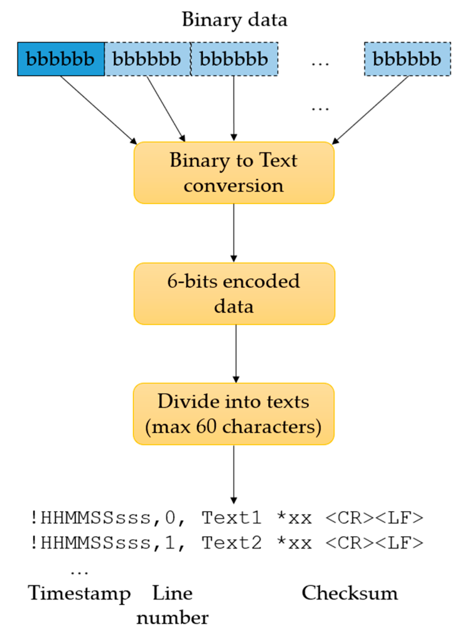
3.2. Proposed Shipboard Data Compression Method
4. Results and Discussion
5. Conclusions
Author Contributions
Funding
Data Availability Statement
Conflicts of Interest
Abbreviations
| ADCP | Acoustic Doppler Current Profiler |
| AIS | Automatic Identification System |
| ASCII | American Standard Code for Information Interchange |
| ASM | Application Specific Messages |
| COG | Course over Ground |
| CPU | Central Processing Unit |
| CSV | Comma Separated Values |
| DP | Dynamic Positioning |
| DSC | Digital Selective Calling |
| ECDIS | Electronic Chart Display and Information System |
| EGC | Enhanced Group Call |
| EM | Electromagnetic |
| EPIRB | Emergency Position Indicating Radio Beacon |
| ETA | Estimated Time of Arrival |
| GMDSS | Global Maritime Distress and Safety System |
| GMSK | Gaussian Minimum Shift Keying |
| GPS | Global Positioning System |
| GT | Gross Tonnage |
| HCS | Heading Control System |
| HF | High Frequency |
| IEC | International Electrotechnical Commission |
| IMO | International Maritime Organization |
| ITU | International Telecommunication Union |
| LAN | Local Area Network |
| LEO | Low Earth Orbit |
| MF | Medium Frequency |
| MMSI | Maritime Mobile Service Identity |
| NBDP | Narrow Band Direct Printing |
| NMEA | National Marine Electronics Association |
| RAIM | Receiver Autonomous Integrity Monitoring |
| RCC | Rescue Coordination Center |
| SAR | Search and Rescue |
| SOG | Speed over Ground |
| SOLAS | International Convention for Safety of Life at Sea |
| TCS | Track Control System |
| TS | Training Ship |
| UTC | Coordinated Universal Time |
| VDE | VHF Data Exchange |
| VDES | VHF Data Exchange System |
| VDR | Voyage Data Recorder |
| VHF | Very High Frequency |
| VTS | Vessel Traffic Service |
References
- Wozniak, J.; Gierlowski, K.; Hoeft, M. Broadband communication solutions for maritime ITSs: Wider and faster deployment of new e-navigation services. In Proceedings of the 2017 15th International Conference on ITS Telecommunications (ITST), Warsaw, Poland, 29–31 May 2017; pp. 1–11. [Google Scholar]
- Wang, J.; Zhou, H.; Li, Y.; Sun, Q.; Wu, Y.; Jin, S.; Quek, T.Q.S.; Xu, C. Wireless channel models for maritime communications. IEEE Access 2018, 6, 68070–68088. [Google Scholar] [CrossRef]
- Habib, A.; Moh, S. Wireless channel models for over-the-sea communication: A comparative study. Appl. Sci. 2019, 9, 443. [Google Scholar] [CrossRef] [Green Version]
- Xia, T.; Wang, M.M.; Zhang, J.; Wang, L. Maritime internet of things: Challenges and solutions. IEEE Wirel. Commun. 2020, 27, 188–196. [Google Scholar] [CrossRef]
- Jiang, Y.; Zheng, Y.; Wang, J. A Novel random access algorithm for very high frequency data exchange (VDE). J. Mar. Sci. Eng. 2020, 8, 83. [Google Scholar] [CrossRef] [Green Version]
- Wei, T.; Feng, W.; Chen, Y.; Wang, C.-X.; Ge, N.; Lu, J. Hybrid Satellite-terrestrial communication networks for the maritime internet of things: Key technologies, opportunities, and challenges. IEEE Internet Things J. 2021, 8, 8910–8934. [Google Scholar] [CrossRef]
- ShipRight Design and Construction. Digital Ships—Procedure for Assignment of Digital Descriptive Notes for Autonomous and Remote Access Ships; Lloyd’s Register: London, UK, 2019. [Google Scholar]
- Sanchez-Gonzalez, P.-L.; Díaz-Gutiérrez, D.; Leo, T.J.; Núñez-Rivas, L.R. Toward Digitalization of maritime transport? Sensors 2019, 19, 926. [Google Scholar] [CrossRef] [Green Version]
- Baldauf, M.; Kitada, M.; Mehdi, R.; Dalaklis, D. E-Navigation, digitalization and unmanned ships: Challenges for future maritime education and training. In Proceedings of the 12th International Technology, Education and Development Conference (INTED), Valencia, Spain, 5–7 March 2018. [Google Scholar]
- International Maritime Organization (IMO) Autonomous Shipping. Available online: https://www.imo.org/en/MediaCentre/HotTopics/Pages/Autonomous-shipping.aspx (accessed on 12 June 2021).
- Levander, O. Autonomous ships on the high seas. IEEE Spectr. 2017, 54, 26–31. [Google Scholar] [CrossRef]
- Ahvenjärvi, S. The Human element and autonomous ships. TransNav. Int. J. Mar. Navig. Saf. Sea Transp. 2016, 10, 517–521. [Google Scholar] [CrossRef] [Green Version]
- Munim, Z.H. Autonomous ships: A review, innovative applications and future maritime business models. Supply Chain Forum Int. J. 2019, 20, 266–279. [Google Scholar] [CrossRef]
- Felski, A.; Zwolak, K. The ocean-going autonomous ship—Challenges and threats. J. Mar. Sci. Eng. 2020, 8, 41. [Google Scholar] [CrossRef] [Green Version]
- Im, I.; Shin, D.; Jeong, J. Components for smart autonomous ship architecture based on intelligent information technology. Procedia Comput. Sci. 2018, 134, 91–98. [Google Scholar] [CrossRef]
- Lopac, N.; Jurdana, I.; Lerga, J.; Wakabayashi, N. Particle-swarm-optimization-enhanced radial-basis-function-kernel-based adaptive filtering applied to maritime data. J. Mar. Sci. Eng. 2021, 9, 439. [Google Scholar] [CrossRef]
- Allal, A.A.; Mansouri, K.; Youssfi, M.; Qbadou, M. Toward energy saving and environmental protection by implementation of autonomous ship. In Proceedings of the 2018 19th IEEE Mediterranean Electrotechnical Conference (MELECON), Marrakech, Morocco, 2–7 May 2018; pp. 177–180. [Google Scholar]
- Lee, P.T.-W.; Kwon, O.K.; Ruan, X. Sustainability challenges in maritime transport and logistics industry and its way ahead. Sustainability 2019, 11, 1331. [Google Scholar] [CrossRef] [Green Version]
- International Telecommunication Union Radiocommunication Sector (ITU-R). Recommendation ITU-R M.1371-5: Technical Characteristics for an Automatic Identification System Using Time Division Multiple Access in the VHF Maritime Mobile Frequency Band; International Telecommunication Union Radiocommunication Sector (ITU-R): Geneva, Switzerland, 2014. [Google Scholar]
- International Maritime Organization (IMO). AIS Transponders. Available online: https://www.imo.org/en/OurWork/Safety/Pages/AIS.aspx (accessed on 12 June 2021).
- Lee, E.; Mokashi, A.J.; Moon, S.Y.; Kim, G. The Maturity of automatic identification systems (ais) and its implications for innovation. J. Mar. Sci. Eng. 2019, 7, 287. [Google Scholar] [CrossRef] [Green Version]
- Wakabayashi, N.; Jurdana, I. Maritime communications and remote voyage monitoring. In Proceedings of the 2020 International Conference on Broadband Communications for Next Generation Networks and Multimedia Applications (CoBCom), Graz, Austria, 7–9 July 2020; pp. 1–8. [Google Scholar]
- Perera, L.P.; Mo, B. Ship performance and navigation data compression and communication under autoencoder system architecture. J. Ocean Eng. Sci. 2018, 3, 133–143. [Google Scholar] [CrossRef]
- International Maritime Organization (IMO). International Convention for the Safety of Life at Sea (SOLAS). 1974. Available online: https://www.imo.org/en/About/Conventions/Pages/International-Convention-for-the-Safety-of-Life-at-Sea-(SOLAS),-1974.aspx (accessed on 12 June 2021).
- International Maritime Organization (IMO). Focus on IMO. Shipping Emergencies—Search and Rescue and the GMDSS; International Maritime Organization (IMO): Lambeth, London, 1999. [Google Scholar]
- International Maritime Organization (IMO). COMSAR/Circ.32. Harmonization of GMDSS Requirements for Radio Installations on Board SOLAS Ships; International Maritime Organization (IMO): Lambeth, London, 2004. [Google Scholar]
- International Maritime Organization (IMO). International Convention for the Safety of Life at Sea (SOLAS), Chapter IV. Radiocommunications; International Maritime Organization (IMO): Lambeth, London, 1974. [Google Scholar]
- International Maritime Organization (IMO). International Convention on Maritime Search and Rescue (SAR). Available online: https://www.imo.org/en/About/Conventions/Pages/International-Convention-on-Maritime-Search-and-Rescue-(SAR).aspx (accessed on 12 June 2021).
- Inmarsat Maritime, Inmarsat Corporate Website. Available online: https://www.inmarsat.com/en/solutions-services/maritime.html (accessed on 12 June 2021).
- Inmarsat Solutions & Services, Inmarsat Corporate Website. Available online: https://www.inmarsat.com/en/solutions-services.html (accessed on 12 June 2021).
- Lázaro, F.; Raulefs, R.; Wang, W.; Clazzer, F.; Plass, S. VHF Data Exchange System (VDES): An enabling technology for maritime communications. CEAS Space J. 2019, 11, 55–63. [Google Scholar] [CrossRef] [Green Version]
- International Maritime Organization (IMO). International Convention for the Safety of Life at Sea (SOLAS), Chapter V. Safety of Navigation; International Maritime Organization (IMO): Lambeth, London, 2002. [Google Scholar]
- Pallotta, G.; Vespe, M.; Bryan, K. Vessel pattern knowledge discovery from AIS data: A framework for anomaly detection and route prediction. Entropy 2013, 15, 2218–2245. [Google Scholar] [CrossRef] [Green Version]
- Liu, J.; Shi, G.; Zhu, K. Vessel Trajectory prediction model based on AIS sensor data and adaptive chaos differential evolution support vector regression (ACDE-SVR). Appl. Sci. 2019, 9, 2983. [Google Scholar] [CrossRef] [Green Version]
- Jiang, Y.; Zheng, K. The single-shore-station-based position estimation method of an automatic identification system. Sensors 2020, 20, 1590. [Google Scholar] [CrossRef] [Green Version]
- Bakdi, A.; Glad, I.K.; Vanem, E.; Engelhardtsen, Ø. AIS-based multiple vessel collision and grounding risk identification based on adaptive safety domain. J. Mar. Sci. Eng. 2020, 8, 5. [Google Scholar] [CrossRef] [Green Version]
- Chao, H.-C.; Wu, H.-T.; Tseng, F.-H. AIS meets IoT: A network security mechanism of sustainable marine resource based on edge computing. Sustainability 2021, 13, 3048. [Google Scholar] [CrossRef]
- International Electrotechnical Commission (IEC). IEC 61162-1 Maritime Navigation and Radiocommunication Equipment and Systems—Digital Interfaces—Part. 1: Single Talker and Multiple Listeners; International Electrotechnical Commission (IEC): Geneva, Switzerland, 2010. [Google Scholar]
- Watanabe, T.; Wakabayashi, N.; Urakami, M.; Terada, D. Development of track control system utilizing heading control system for ocean observation sailing. In Proceedings of the 27th International Ocean and Polar Engineering Conference, International Society of Offshore and Polar Engineers (ISOPE), San Francisco, CA, USA, 25–30 June 2017; pp. 529–536. [Google Scholar]
- Wakabayashi, N.; Watanabe, T.; Urakami, M.; Terada, D. Development of simple dynamic positioning system—Algorithm and user interface. In Proceedings of the 27th International Ocean and Polar Engineering Conference, International Society of Offshore and Polar Engineers (ISOPE). San Francisco, CA, USA, 25–30 June 2017; pp. 507–512. [Google Scholar]
- Wakabayashi, N.; Watanabe, T.; Urakami, M.; Yano, Y. Tablet control system for offshore support and research vessel—development, implementation, and operational testing. In Proceedings of the 28th International Ocean and Polar Engineering Conference, International Society of Offshore and Polar Engineers (ISOPE), Sapporo, Japan, 10–15 June 2018; pp. 922–928. [Google Scholar]
- Wakabayashi, N.; Yano, Y.; Shiotani, S.; Murai, K. Sailing data transfer and display system using wireless LAN in the bridge and its application to navigation support system. In Proceedings of the 11th IAIN (International Association of Institutes of Navigation) World Congress, Berlin, Germany, 21–24 October 2003; Volume 160, pp. 42–46. [Google Scholar]
- Fujii, M.; Hayashi, M.; Urakami, M.; Wakabayashi, N. The development of meteorological and oceanographic data collection and recording system operating on training ship. In Proceedings of the ASME 2014 33rd International Conference on Ocean, Offshore and Arctic Engineering, San Francisco, CA, USA, 8–13 June 2014; Volume 8B, p. V08BT06A007. [Google Scholar]
- Wakabayashi, N.; Watanabe, T.; Urakami, M.; Yano, Y. Motor vessel LAN—Design, implementation, and operation. In Proceedings of the 2018 International Conference on Broadband Communications for Next Generation Networks and Multimedia Applications (CoBCom), Graz, Austria, 11–13 July 2018; pp. 1–8. [Google Scholar]
- National Marine Electronics Association (NMEA). NMEA 0183 Standard for Interfacing Marine Electronic Devices Version 3.01; National Marine Electronics Association (NMEA): Severna Park, MD, USA, 2002. [Google Scholar]


| Device Code | Data Source Device |
|---|---|
| 0 | Voyage Data Recorder (VDR) |
| 1 | GPS |
| 2 | GPS compass |
| 3 | GPS compass |
| 4 | Doppler sonar |
| 5 | Gyrocompass |
| 6 | Magnet compass |
| 7 | Electromagnetic (EM) log |
| 8 | Doppler log |
| 9 | Accelerometer |
| N | Navigation data collection equipment |
| D | Weather (Analog) |
| A | AIS |
| R | Radar 1 |
| S | Radar 2 |
| W | Weather transmitter |
| E | Engine data logger |
| C | Central Processing Unit (CPU) control system |
| H | Acoustic Doppler Current Profiler (ADCP) |
| B | Sea water monitor |
| Lower Digit | Upper Digit | |||||||
|---|---|---|---|---|---|---|---|---|
| 0 | 1 | 2 | 3 | 4 | 5 | 6 | 7 | |
| 0 | NUL | DLE | SP | 0 | @ | P | ‘ | p |
| 1 | SOH | DC1 | ! | 1 | A | Q | a | q |
| 2 | STX | DC2 | “ | 2 | B | R | b | r |
| 3 | ETX | DC3 | # | 3 | C | S | c | s |
| 4 | EOT | DC4 | $ | 4 | D | T | d | t |
| 5 | ENQ | NAK | % | 5 | E | U | e | u |
| 6 | ACK | SYN | & | 6 | F | V | f | v |
| 7 | BEL | ETB | ‘ | 7 | G | W | g | w |
| 8 | BS | CAN | ( | 8 | H | X | h | x |
| 9 | HT | EM | ) | 9 | I | Y | i | y |
| a | LF | SUB | * | : | J | Z | j | z |
| b | VT | ESC | + | ; | K | [ | k | { |
| c | FF | FS | , | < | L | \ | l | | |
| d | CR | GS | - | = | M | ] | m | } |
| e | SO | RS | . | > | N | ^ | n | ~ |
| f | SI | US | / | ? | O | _ | o | DEL |
| Valid Character | Binary Field | Valid Character | Binary Field |
|---|---|---|---|
| 0 | 000000 | P | 100000 |
| 1 | 000001 | Q | 100001 |
| 2 | 000010 | R | 100010 |
| 3 | 000011 | S | 100011 |
| 4 | 000100 | T | 100100 |
| 5 | 000101 | U | 100101 |
| 6 | 000110 | V | 100110 |
| 7 | 000111 | W | 100111 |
| 8 | 001000 | X | 101000 |
| 9 | 001001 | Y | 101001 |
| : | 001010 | Z | 101010 |
| ; | 001011 | [ | 101011 |
| < | 001100 | \ | 101100 |
| = | 001101 | ] | 101101 |
| > | 001110 | ^ | 101110 |
| ? | 001111 | _ | 101111 |
| @ | 010000 | ‘ | 110000 |
| A | 010001 | a | 110001 |
| B | 010010 | b | 110010 |
| C | 010011 | c | 110011 |
| D | 010100 | d | 110100 |
| E | 010101 | e | 110101 |
| F | 010110 | f | 110110 |
| G | 010111 | g | 110111 |
| H | 011000 | h | 111000 |
| I | 011001 | i | 111001 |
| J | 011010 | j | 111010 |
| K | 011011 | k | 111011 |
| L | 011100 | l | 111100 |
| M | 011101 | m | 111101 |
| N | 011110 | n | 111110 |
| O | 011111 | o | 111111 |
| NMEA (ASCII Text) | Differential Binary | ||||
|---|---|---|---|---|---|
| Day | Size (bytes) | Transmission Rate (bps) | Size (bytes) | Transmission Rate (bps) | Percentage of Original Rate |
| 1 | 420 075 869 | 38 896 | 12 834 787 | 1 188 | 3.1% |
| 2 | 383 417 540 | 35 502 | 14 322 600 | 1 326 | 3.7% |
| 3 | 378 660 939 | 35 061 | 12 747 110 | 1 180 | 3.4% |
| 4 | 333 396 756 | 30 870 | 10 005 819 | 926 | 3.0% |
| 5 | 373 968 226 | 34 627 | 13 126 548 | 1 215 | 3.5% |
| 6 | 379 365 849 | 35 126 | 12 729 161 | 1 179 | 3.4% |
| 7 | 374 306 715 | 34 658 | 14 455 567 | 1 338 | 3.9% |
| 8 | 417 087 087 | 38 619 | 13 881 659 | 1 285 | 3.3% |
| 9 | 381 812 092 | 35 353 | 13 959 130 | 1 293 | 3.7% |
| 10 | 387 986 049 | 35 925 | 14 175 340 | 1 313 | 3.7% |
| 11 | 388 698 134 | 35 991 | 10 983 768 | 1 017 | 2.8% |
| 12 | 405 285 135 | 37 526 | 12 475 967 | 1 155 | 3.1% |
| 13 | 496 322 151 | 45 956 | 16 696 313 | 1 546 | 3.4% |
| 14 | 497 851 142 | 46 097 | 16 887 465 | 1 564 | 3.4% |
| 15 | 467 942 678 | 43 328 | 11 513 411 | 1 066 | 2.5% |
| 16 | 317 855 596 | 29 431 | 12 988 511 | 1 203 | 4.1% |
| 17 | 319 283 225 | 29 563 | 12 574 645 | 1 164 | 3.9% |
| 18 | 309 706 452 | 28 677 | 11 375 970 | 1 053 | 3.7% |
| 19 | 305 818 152 | 28 316 | 10 162 442 | 941 | 3.3% |
| 20 | 316 926 862 | 29 345 | 12 747 204 | 1 180 | 4.0% |
| 21 | 316 142 108 | 29 272 | 12 950 912 | 1 199 | 4.1% |
| 22 | 305 996 268 | 28 333 | 11 413 855 | 1 057 | 3.7% |
| Total | 8 277 905 025 | 285 008 184 | |||
| Average | 376 268 410 | 34 840 | 12 954 917 | 1 200 | 3.4% |
| St. dev. | 57 362 724 | 5 311 | 1 716 563 | 159 | 0.4% |
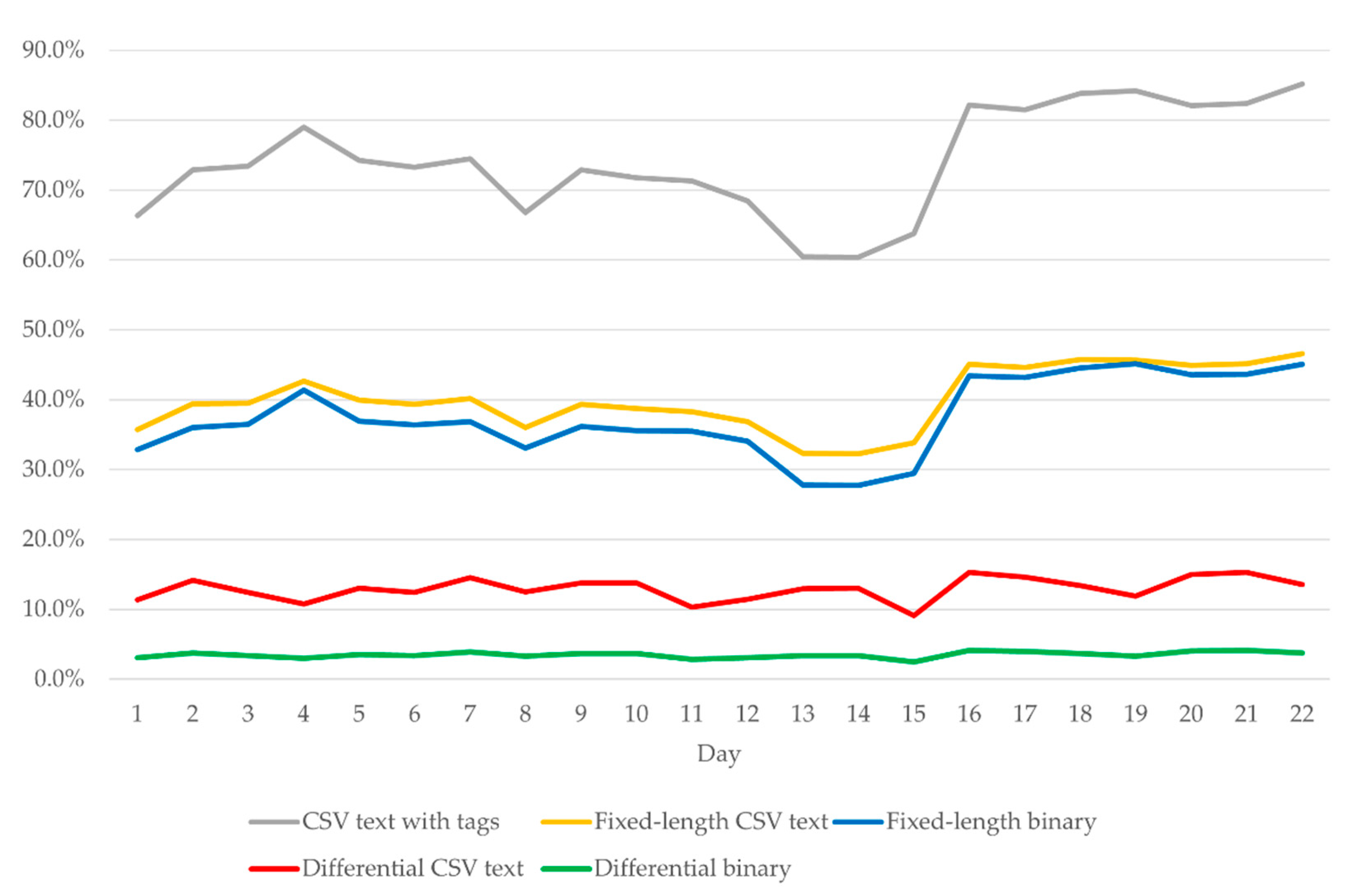
| CSV Text with Tags | Fixed-Length CSV Text | Fixed-Length Binary | Differential CSV Text | Differential Binary | |
|---|---|---|---|---|---|
| Average | 73.0% | 39.4% | 36.7% | 12.8% | 3.4% |
| St. dev. | 7.5% | 4.4% | 5.4% | 1.6% | 0.4% |
| Comp. time | 0.001324 s | 0.001320 s | 0.000379 s | 0.000537 s | 0.000253 s |
Publisher’s Note: MDPI stays neutral with regard to jurisdictional claims in published maps and institutional affiliations. |
© 2021 by the authors. Licensee MDPI, Basel, Switzerland. This article is an open access article distributed under the terms and conditions of the Creative Commons Attribution (CC BY) license (https://creativecommons.org/licenses/by/4.0/).
Share and Cite
Jurdana, I.; Lopac, N.; Wakabayashi, N.; Liu, H. Shipboard Data Compression Method for Sustainable Real-Time Maritime Communication in Remote Voyage Monitoring of Autonomous Ships. Sustainability 2021, 13, 8264. https://doi.org/10.3390/su13158264
Jurdana I, Lopac N, Wakabayashi N, Liu H. Shipboard Data Compression Method for Sustainable Real-Time Maritime Communication in Remote Voyage Monitoring of Autonomous Ships. Sustainability. 2021; 13(15):8264. https://doi.org/10.3390/su13158264
Chicago/Turabian StyleJurdana, Irena, Nikola Lopac, Nobukazu Wakabayashi, and Hongze Liu. 2021. "Shipboard Data Compression Method for Sustainable Real-Time Maritime Communication in Remote Voyage Monitoring of Autonomous Ships" Sustainability 13, no. 15: 8264. https://doi.org/10.3390/su13158264
APA StyleJurdana, I., Lopac, N., Wakabayashi, N., & Liu, H. (2021). Shipboard Data Compression Method for Sustainable Real-Time Maritime Communication in Remote Voyage Monitoring of Autonomous Ships. Sustainability, 13(15), 8264. https://doi.org/10.3390/su13158264