Abstract
Biofilms are a complex and heterogeneous aggregation of multiple populations of microorganisms linked together by their excretion of extracellular polymer substances (EPS). Biofilms can cause many serious problems, such as chronic infections, food contamination and equipment corrosion, although they can be useful for constructive purposes, such as in wastewater treatment, heavy metal removal from hazardous waste sites, biofuel production, power generation through microbial fuel cells and microbially enhanced oil recovery; however, biofilm formation and growth are complex due to interactions among physicochemical and biological processes under operational and environmental conditions. Advanced numerical modeling techniques using the lattice Boltzmann method (LBM) are enabling the prediction of biofilm formation and growth and microbial community structures. This study is the first attempt to perform a general review on major contributions to LBM-based biofilm models, ranging from pioneering efforts to more recent progress. We present our understanding of the modeling of biofilm formation, growth and detachment using LBM-based models and present the fundamental aspects of various LBM-based biofilm models. We describe how the LBM couples with cellular automata (CA) and individual-based model (IbM) approaches and discuss their applications in assessing the spatiotemporal distribution of biofilms and their associated parameters and evaluating bioconversion efficiency. Finally, we discuss the main features and drawbacks of LBM-based biofilm models from ecological and biotechnological perspectives and identify current knowledge gaps and future research priorities.
1. Introduction
Bacteria mainly live together, forming complex and heterogeneous aggregations of structured communities connected together by their excretion of extracellular polymer substances (EPS). Such aggregates of microorganisms are called biofilms. Biofilms can consist of bacteria and various non-cellular materials such as mineral crystals, corrosion particles, clay or silt particles, or blood components, depending on the environment in which the biofilm has developed. Biofilms often contain one or more microbial species, which adhere to each other; to surfaces (living or non-living); and to solid–liquid, liquid–air, liquid–liquid and solid–air interfaces [1]. Biofilms can cause many industrial and biological problems, such as chronic infections, food contamination, biofouling and equipment corrosion, although they have been applied for a variety of industrial applications, such as in biohydrogen production, fermentative food processing, power generation through microbial fuel cells, biological wastewater treatment and microbial-enhanced oil recovery [2,3,4,5,6,7,8,9,10,11,12,13,14,15]. As such, it is important to understand the mechanisms of biofilm formation, growth and detachment, as well as their interactions with their surrounding environments, the social interactions between single-species and multispecies biofilms and the potential applications of biofilms for environmental protection and enhanced biotechnology. Extensive efforts have been made to understand the mechanisms of biofilm growth and their interactions with the affective signals [3,16,17,18,19,20,21,22,23,24]. Due to the very complex interactions among physicochemical and biological processes, direct measurement of the impacts of bioactivity on transport dynamics in 3D structures is very difficult due to sample opacity [25,26]; thus, many numerical models have been developed to examine biofilm growth, which can be categorized into discrete or particle-based models and continuum models [27,28].
1.1. Mathematical Models of Biofilms
Biofilm modeling dates back to the 1970s. Biofilms were originally described as uniform biomasses of single microorganism species [29,30]. The first-generation biofilm models can be implemented quickly and easily but they cannot capture certain details of biofilm structures. Later, stratified biofilms were dynamically modeled [31]. These one dimensional (1D) stratified models were evolved to describe multi-substrate and multi-species interactions within the biofilm as the second-generation models; however, the second-generation models were not capable of describing the characteristic structural heterogeneity of biofilms. As such, discrete models of biofilm growth were developed in the 1990s and have continued until the current day as the third-generation mathematical models. Cellular automata (CA) or individual-based models (IbM) are two of the discrete model types, which have been used for simulations of inherently stochastic and individual cells and for cell spreading at the local level [32]. The rules used to model the interactions at the local level can be determined not only through biological principles, but also through mathematical and physical frameworks using CA or IbM approaches. Hydrodynamics and multispecies transport are solved using the finite difference method (FDM), finite volume method (FVM), or finite element method (FEM). As bottom-up models, the third-generation biofilm models allow the description of the sophisticated two- (2D) and three-dimensional (3D) structures and morphologies of microbial biofilms. They can incorporate not only substrate transport and transformations [33,34], but also hydrodynamics [35] and population dynamics [36]. The large-scale morphology dynamics results from the interactions of the small-scale individual cells and the environment; however, the third-generation biofilm models have difficulty in accounting for complex non-equilibrium interface dynamics, multiphase flow with phase changes and complex geometries, such as porous media.
1.2. History of Lattice Boltzmann Equation in Modeling of Biofilms
The lattice Boltzmann method (LBM)-based models are more recent in the field of biofilm modeling research than others using FDM or FVM. LBM approaches are particle-based, bottom-up models that are considered suitable for tracing the dynamics and properties of individual bacterial cells. Conversely, the behavior of individual cells is not directly tracked in continuum models and the biofilm is modeled using volume- or mass-averaged behaviors of different functional groups. The first attempt to model biofilm growth using LBM can be dated back to 1999 by Picioreanu et al. [35,37]. In the 2000s, many researchers used the LBM approach to study biofilm growth [34,38,39,40,41]. In LBM-CA models, the CA describes the spreading possess for a limited number of directions and with ad hoc or probabilistic rules [42,43]. In the LBM-based biofilm models, biofilm growth is simulated through coupling with either IbM (e.g., LBM-IbM) [28,44] or with CA (e.g., LBM-CA) [3,19,35,37]. In recent years, LBM-based models have been extended to the modeling of several key processes, such as multispecies competition and cooperation [3], the thermal effects on biofilm growth [19,20], the effects of pH values on biofilm growth [21] and heterogeneous permeability in biofilms [28]. The LBM-based models are very effective in modeling complex multilateral interactions among biofilm growth, transport phenomenon and hydrodynamics, allowing better and more detailed description of processes in different industrial or academic applications. Here, we call the LBM-based biofilm models as the fourth-generation models. Despite remarkable advances in modeling biofilm formation and growth, the LBM-based biofilm models have not yet been reviewed.
This review aims to synthesizes our understanding in modeling the biofilm formation, growth and detachment using LBM-based models. We present the fundamentals of various LBM-based biofilm models and how the LBM couples with CA or IbM with their applications for the simulation of spatiotemporal distribution of biofilms and bioconversion in biotechnologies and bioengineering. Finally, we highlight the value of an ecological and biotechnological perspective and identify current knowledge gaps and future research priorities.
2. Multiscale Biofilm Formation Processes and Lattice Boltzmann Method
Biofilm growth, formation and detachment are multiscale processes in nature [45]. Biofilm growth links cell and population scales and interacts with hydrodynamic and nutrient. Their multiscale nature requires to incorporate more intracellular states, behaviors and interplay among biofilm growth, reaction-diffusion and hydrodynamics in quantitative modeling of biofilms.
2.1. Multiscale Biofilm Processes
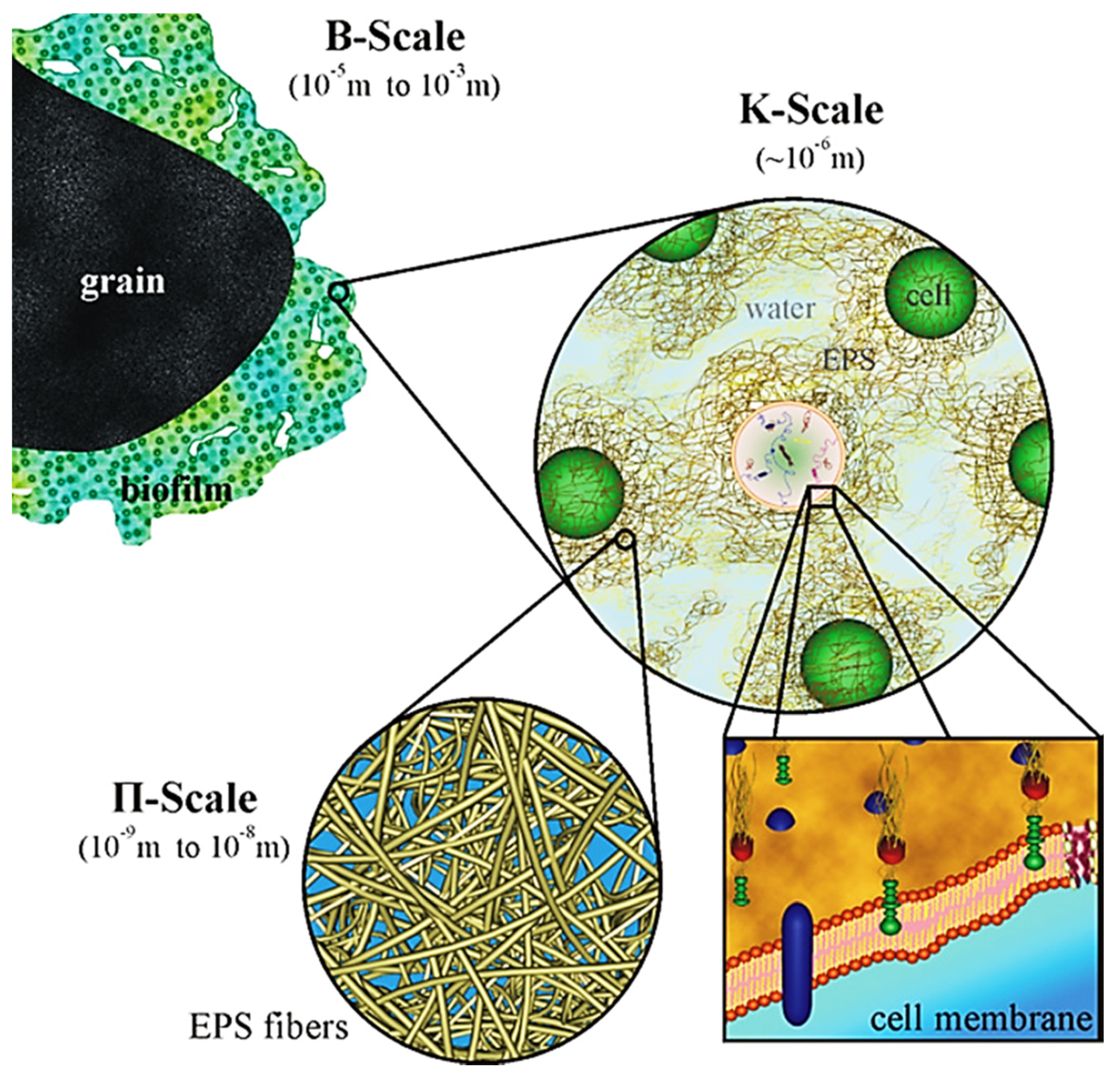
Biofilms are ubiquitous in nature and are persistently sticked to both biotic and abiotic surfaces ranging from the human tooth or lung to a rock submerged in a stream and/or reactor wall. Therefore, many studies of biofilms have been performed due to their importance in infectious disease processes in clinical and public health [46] and bioconversion in biotechnology [19,20]. Medical devices may be colonized by biofilms, resulting in measurable rates of device-associated infections. Bacterial biofilms are mostly composed of multiple populations of different bacterial species in hierarchical structure of a microbial biofilm [47] (Figure 1). Each population needs to be adapted to either environmental fluctuations, such as nutrient and water availability, temperature, moisture and pH value, or metabolism and migration of other species. Therefore, the surviving of any given population in a multispecies biofilm greatly relies on the three universal types of processes occurring in a biofilm system: transformations (e.g., substrate utilization), transport (e.g., convection and diffusion) and biofilm formation and growth.
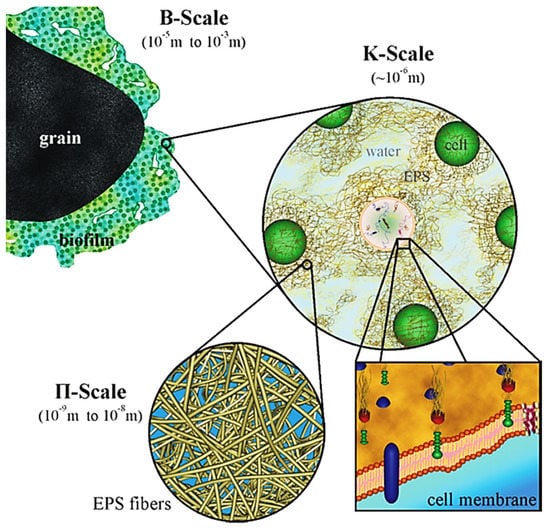
Figure 1.
Schematic representation of the hierarchical structure of a microbial biofilm (Reprinted from [47] with permission from Elsevier).
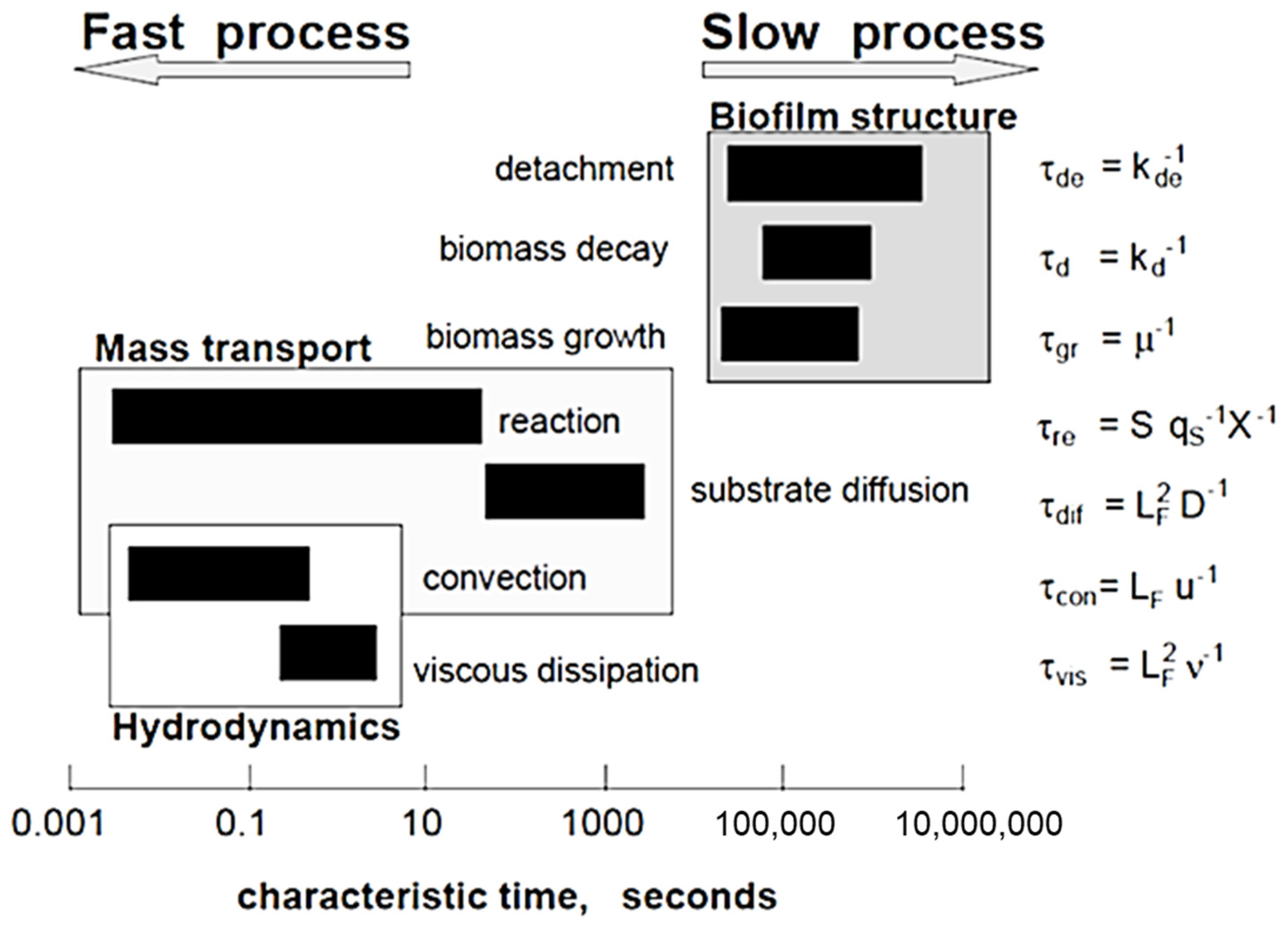
Figure 2 shows the hierarchical characteristic time scale for microbial biofilm growth and fluid flow processes that occur in a biofilm community [48]. The order of magnitude of the characteristic times can be represented by dimensionless forms [48]:
where τgr is the characteristic time for biomass growth, τdif is the time of substrate transport by diffusion and LF is the biofilm thickness. The difference of characteristic times could be large as 10 orders of magnitude, although a specific time scale can change from minutes to months, relying on the processes of most interest. Biofilm growth has a time scale > 105 s (~1 day). In contrast, hydrodynamic changes occur at a time scale usually less than 1 s. This means that hydrodynamic conditions are changed quickly but the change of other biofilm components is so slow that they can be presumed as a constant state. Thus, this provides the possibility to reduce drastically the computational effort without sacrificing accuracy if multiscale modeling approaches are used.
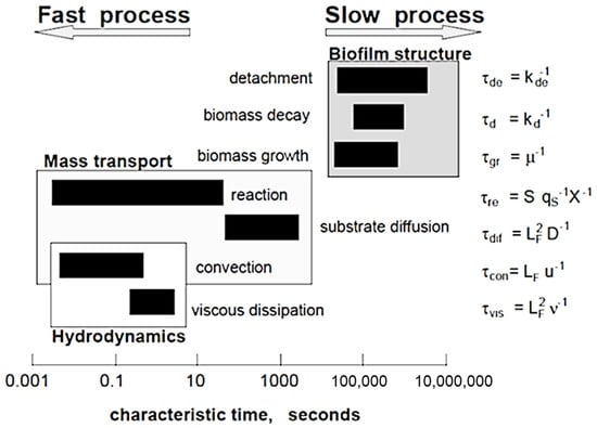
Figure 2.
Characteristic times of different processes occurring in reactive transport and biofilm systems (Reprinted from [48] with permission from John Wiley and Sons).
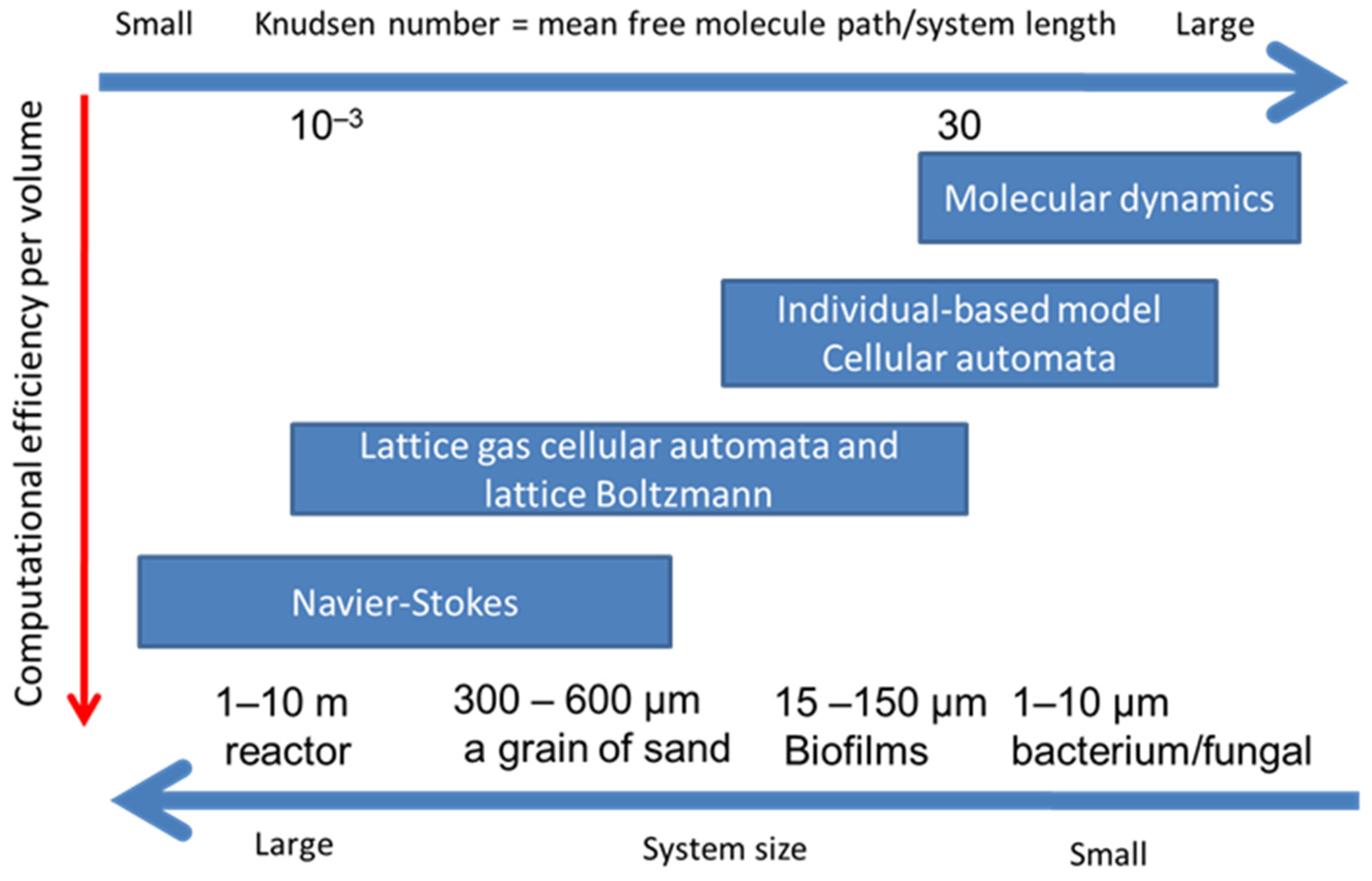
There are several numerical methods to simulate transport phenomenon from macroscopic continuum media to microscopic scheme (Figure 3). In the macroscopic methods, the domain is treated as a continuum media such as Navier–Stokes equation which is used in fluid mechanics and thermodynamics. On the other hand, in microscopic methods of molecular dynamics (MD), the domain is considered as small particles such as atoms, molecules or parcels. Both methods can produce acceptable outcomes when the system involves enough large number of particles.
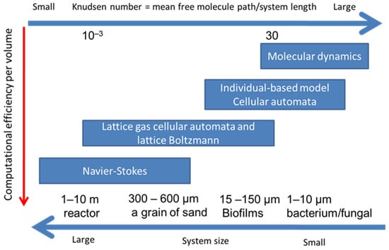
Figure 3.
Various approaches to hydrodynamics and reactive transport together with their preferred range of applicability.
Molecular dynamics is based on the Lagrangian specification of the flow field in which an individual fluid parcel or molecule moves through space and time according to Newton’s law and an intermolecular potential. In CA models, the biomass in a grid is represented using volume averaged variables of properties (density or concentration) and is represented as percentage of whole area (2D) or volume (3D). The set of CA rules is used to describe the interaction of cells with each other and its neighborhood in the lattice network. Each rule designates one of the main processes occurring in biofilm, such as spreading direction, biofilm growth and decay and biofilm distribution. Cell movement is limited in the finite number of lattice directions. In contrast, the IbM is a type of multiscale models to represent the interactions among individual cells, population or community [43,49]. A bacterial cell is assumed as a sphere which is characterized by essential variables, such as volume, mass and density. These spherical cells can locate anywhere in continuous 3D space and act independently under a set of rules, analogous to behaviors of individual bacterial cells, such as biofilm growth, cell division and production of metabolites. IbM allows off-lattice cell movement on a continuous set of directions and distances. This type of IbMs overcome the drawbacks deriving from the discrete rules to biofilm spreading in the CA approach [34]. In biofilm modeling, both CA and IbM do not simulate reactive transport of a solute species and fluid flow. When movement of particles is controlled by Newton’s law, CA can be used for simulation of hydrodynamics and reactive transport. Such a CA algorithm is called as lattice gas cellular automata (LGCA) [50].
LBM originated from classical statistical physics and lattice gas automata (LGCA) [50]. In LBM, there are two main practical modifications: (1) The distribution functions of particles replace the tracing of each particle. This allows a group/parcel of atoms or molecules to represent individual particles and significantly reduces simulation scale from microscopic to mesoscopic scale, that considerably saves the computational time. (2) The degree of freedom of particles movement is reduced to restrict the movement of particles to a finite number of directions. LBM treats flows in terms of fictive parcels of particles which reside on a mesh and conduct translation according to collision steps entailing overall fluid-like behavior. The statistical noise of LGCA was eliminated due to using a continuous distribution function and the collision operator within Bhatnagar–Gross–Krook (LBGK) model [51]. LBM can recover macro governing equations of transport phenomenon, including momentum, energy and mass transfer using correctly choosing the equilibrium distribution functions after implementation of the Chapman–Enskog multiscale expansion [52,53,54]. This makes LBM more efficient, stable and flexible in hydrodynamics modeling.
Figure 3 shows four groups of methods which can describe the conservation of mass, momentum and energy at computational grids. These methods have their respective strengths at different Knudsen numbers. The Knudsen number is the ratio of the mean free molecule path to the representative system length, which is a characteristic length scale representing spatial resolution, such as bacterium and the sand size [55]. Navier–Stokes approaches solve continuum-based partial differential equations using FDM or FVM at a larger spatial scale, while MD, CA or IbM approaches are suitable processes at microscale. LBM and LGCA are at mesoscale between macroscale of Navier–Stokes approaches and microscale of MD. Therefore, LBM is more suitable for simulations of reactive transport and fluid flow with biofilm growth at meso or macroscale.
2.2. Lattice Boltzmann Equation
Compared to traditional computational fluid dynamics (CFD) using FDM or FVM, LBM, due to its fundamental kinetic nature, has a number of key benefits, such as easier parallelization, handling of pressure field (no need to solve the Poisson equation that is computationally expensive), complex boundary conditions and geometries and interface interactions. These advantages make LBM an ideal scale-bridging scheme to integrate simplified kinetic models with hydrodynamics in the simulation of microscopic/mesoscopic processes and biofilm growth.
In biofilm modeling, the system must be governed by the mass, energy and momentum conservations with their initial and boundary conditions. The substrate conservation is described by the reactive transport equation. The flow field is expressed by the Navier–Stokes equation and the continuity equation. The set of conservation equations is mathematically complicated and difficult to be handled analytically. Thus, the set of conservation equations have been solved using numerical methods, such as FDM and LBM.
In lattice Boltzmann method, as a mesoscopic approach, the movement of groups of fluid particles are modeled to capture macroscopic quantities such as velocity during two processes, streaming and collision. This modeling is established using the distribution function, f(x, c, t), which is defined as the number of particles in time t, with velocity ranging from c to c + dc, located in the position between x and x + dx. The distribution function stands as a replacement of each single particle in molecular dynamics which leads to substantial saving in computational cost and making simulations feasible for larger computational domain, compared to ones for molecular dynamics.
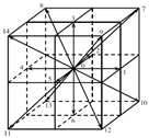
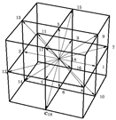
In LBM, the domain is discretized to uniform Cartesian cells (often squares in 2D or cubes in 3D). The movement of particles (group of atoms or molecules) is limited to a number of specific directions, depending on LBM schemes. The DnQm scheme is widely used for classifying the different LBM methods is. In the DnQm scheme, n represents the dimension of model (2 for two-dimensional and 3 for three-dimensional) and m does the number of specific streaming directions. For example, D2Q9 represents two-dimensional model with nine velocity directions. Table 1 shows several commonly-used 2D and 3D LBM schemes. For D2Q9, the model equations are expressed as:
where stands for collision frequency, is for relaxation factor and represents the local equilibrium distribution function. Subscript k denotes the streaming direction of LBM model. The set of LBM equations can recover the continuity of mass and momentum (Navier–Stokes) equations by using the Chapman–Enskog multiscale expansion [56,57]:

Table 1.
Common Lattice Boltzmann Models.
To consider all fluid flow, temperature field and species transport, the conservations of energy and species concentration in the domain can be described as the below reactive transport equation and temperature equation:
where T is local temperature, is thermal diffusion coefficient, is the heat source.
Corresponding distribution function for each parameter is required if LBM is applied to solve scalar parameters such as concentration and temperature in the domain. Thus, different distribution functions, and , are defined for every scalar parameter, respectively [19,20].
The is the distribution function used for temperature calculation:
where is the corresponding equilibrium distribution function, is time step that should be adjusted by macroscopic time step and is the heat source. For the temperature as a scalar variable, the equilibrium distribution function is determined by [3,19,54,58,59,60]:
The source term, , is a function of heat source, , as:
As there are more than one species in biofilm growth systems, the concentration field of multispecies reactive transport can be described as
where is the specific heat capacity, represents the concentration fraction of species , is the mass generation rate for the species per unit volume and time and is the effective diffusion coefficient of the lth species. Subscript l denotes the lth species.
The concentration field of each species (as a scalar parameter which is similar as temperature) can be simulated using corresponding distribution functions, , defined as below [3,19,20,21,59]:
where is the distribution function of the lth species.
Having calculated distribution functions, the temperature and species concentrations are calculated as:
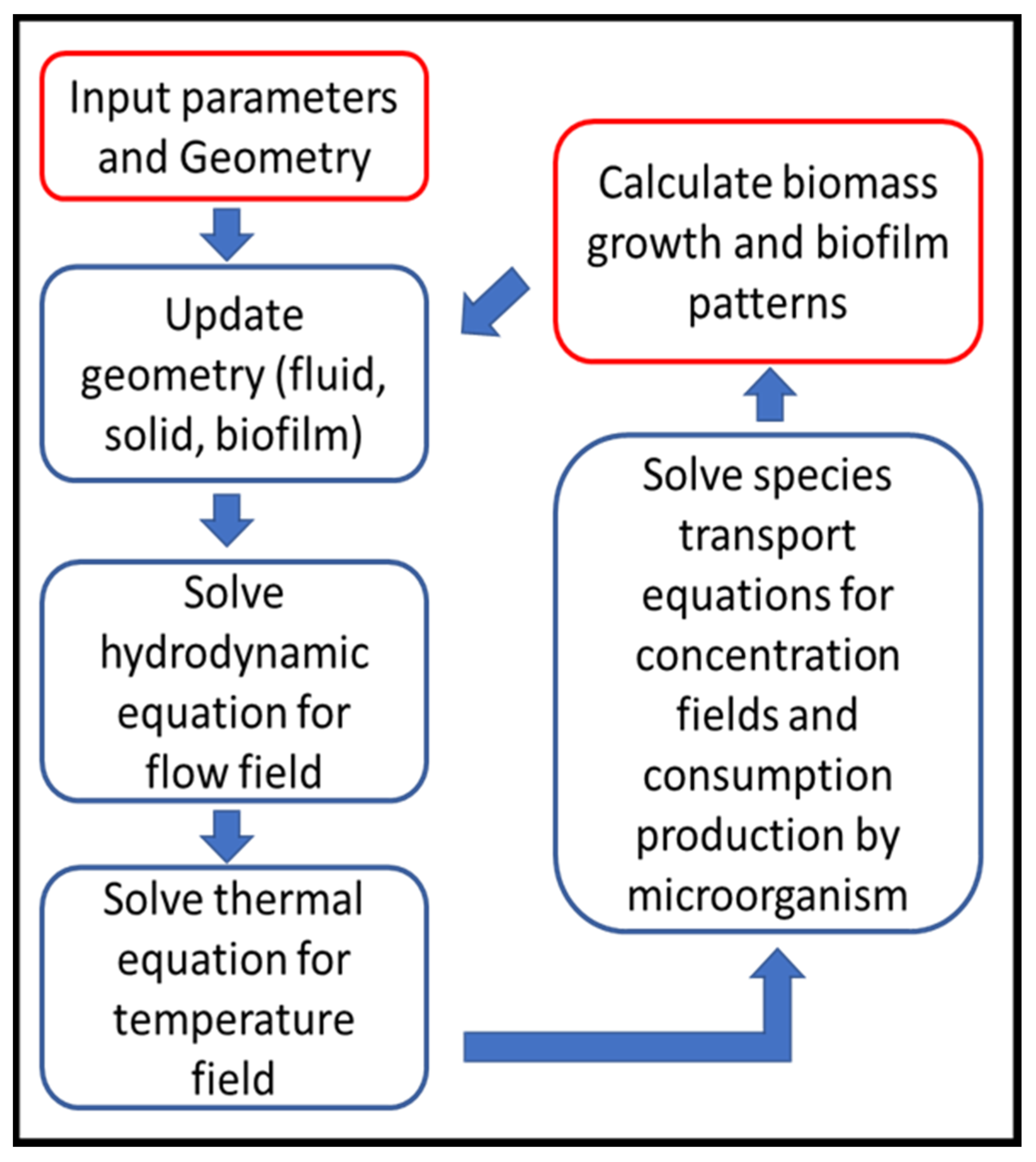
Although each biofilm simulation has its own known and unknown parameters that affect the simulation process, a general simulation procedure would generally be applicable to LBM simulations, shown in Figure 4 [19]:
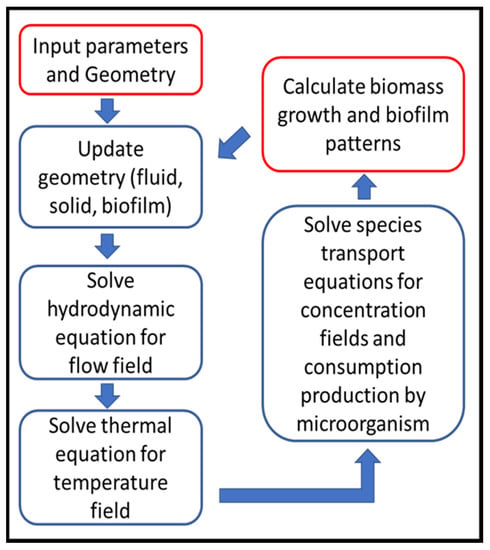
Figure 4.
LBM simulation flow chart (Reprinted from [19] with permission from American Chemical Society).
- Geometry definition: as the first step, the computational domain is defined regarding to the bioreactor geometry.
- There are usually three types of zones in the domain as fluid, solid, biofilm that are updated in this step due to initial geometry or zones calculated in previous time step.
- Solve the hydrodynamic equations (Equations (2) and (3)) to capture local velocity vectors.
- Solve energy/temperature equations (Equations (7) and (8)) to find local temperature and update fluid and species properties, if they are considered temperature dependent.
- Solve the species transport equations (Equations (11) and (12)), that gives local species concentration and consumption by bacteria regarding to local fluid velocity, temperature and concentrations of nutrients.
- Biomass calculation (its concentration, detachment and shrinkage) in each grid in order to determine the biofilm growth and spread of growth and spread.
- Update biofilm pattern, affecting flow connection channels.
- Return to Step (2) for the next time step, calculations continue up to desired total simulation time.
3. Applications of LBM-Based Biofilm Models to Biotechnology and Bioengineering
LBM-based biofilm models are based on the idea that flow field, substrate fields and temperature field can be solved by LBM while biofilm growth can be characterized using IbM or CA. Therefore, an LBM-based approach is essentially a hybrid scheme. Because modeling biofilm growth, detachment, attachment and shrinkage have two approaches: IbM and CA, an LBM model can couple with one of them to solve interactions among biofilm growth, flow and reactive transport and temperature. These hybrid models have shown their capability in representing the biofilm structure heterogeneity. In this section, we classify the LBM-based biofilm models as three types: LBM with no biofilm pattern, LBM coupled with CA (LBM-CA) and LBM coupled with IbM (LBM-IbM).
3.1. LBM for Biological Reaction with no Biofilm Growth
LBM can describe biological reaction without tracing biofilm growth. In such LBM model, flow and reactive transport, such as temperature and substrate concentration, are solved using LBM. Substrate consumptions are calculated by using zero, the first order or Monod kinetics but biofilm growth patterns will not be traced. Graf von der Schulenburg et al. [61] developed an LBM model coupled with a directed random walk algorithm to study the hydrodynamics of flow induced by biofilm in a randomly packed bed. They investigated the irregular transport dynamics due to effects of biofilms and examined the effects of observation time on the displacement distributions (propagators). They reported that increasing observation time caused propagators to have a transition from a pre-asymptotic to a Gaussian-shaped distribution. In both situations with and without biofilm growth, this transition was observed; however, it was very significantly delayed due to the significant development of essentially stagnant regions if the biofilm was present.
Zhang et al. [62] used lattice Boltzmann method to simulate fluid flow and mass transfer and their effects on an herbicide-degrading bacterium growth rate in porous media. They investigated the effects of the heterogeneity of pore structures and transverse mixing on the growth of a pure culture (Delftia acidovorans) degrading (R)-2-(2, 4-dichlorophenoxy) propionate (R-2, 4-DP). Figure 5 shows reaction rate contours in homogeneous and aggregate pore networks. Although they experimentally observed biofilm growth, they used LBM to simulate the reaction rate without biofilm growth. The results could contribute to enhance the knowledge of biofilm growth in complex porous media affected by the coupling between fluid flow, species mass transfer and bioreaction rates.

Figure 5.
Reaction rate contours in mol.m−3.s−1, in homogeneous and aggregate pore networks, for reaction rate constants (Da = 1.39) (Reprinted from [62] from with permission American Chemical Society).
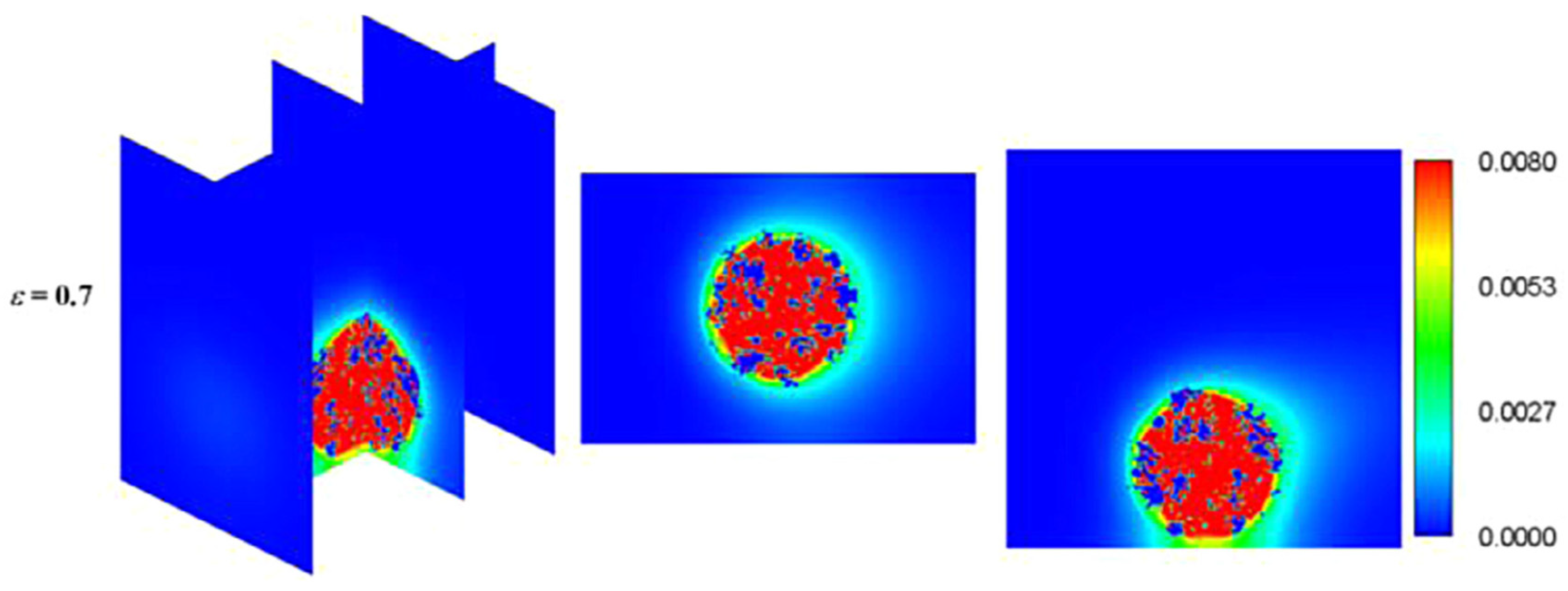
Hydrogen is considered as high energy density and renewable energy source and has an enormous potential to replace fossil fuels. Hydrogen can be generated through some microbial processes such dark and photo fermentation that are eco-friendly production technologies having a huge potential to be a leading future-interest energy technology [21]. Yang et al. [63] numerically investigated hydrogen production by photosynthetic bacteria (PSB) in a biofilm bioreactor using LBM. They investigated the biochemical reaction in an attached thin PSB biofilm to a circular cylinder considering the curved boundaries. The substrate consumption efficiency and the hydrogen yield were examined for different Reynolds and Sherwood numbers that represented different fluid velocity and mass transfer characteristics. The simulated results were validated against the drag and lift coefficients and concentration profiles of theoretical/numerical data available in the literature. They found that the concentrations of both the substrate and products decrease with increasing Reynolds number. However, they did not include biofilm growth. Liao et al. [64,65] simulated biohydrogen production through photo fermentation in photobioreactor. They used LBM to simulate fluid flow and species transport in the bioreactor and evaluated the impacts of accumulation mode of particles, fluid velocity, porosity of immobilized granule and illumination intensity on biohydrogen production performance in terms of the substrate consumption efficiency and hydrogen yield. Figure 6 shows biohydrogen concentration fields around the immobilized granule [65]. However, they did not consider biofilm growth as they calculated photo fermentative biohydrogen production assuming a biofilm region in the domain without considering biofilm growth.
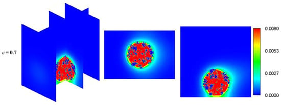
Figure 6.
Concentration fields of biohydrogen concentration around the immobilized granule (Reprinted from [64] with permission from Elsevier).
3.2. LBM-CA Based Biofilm Models
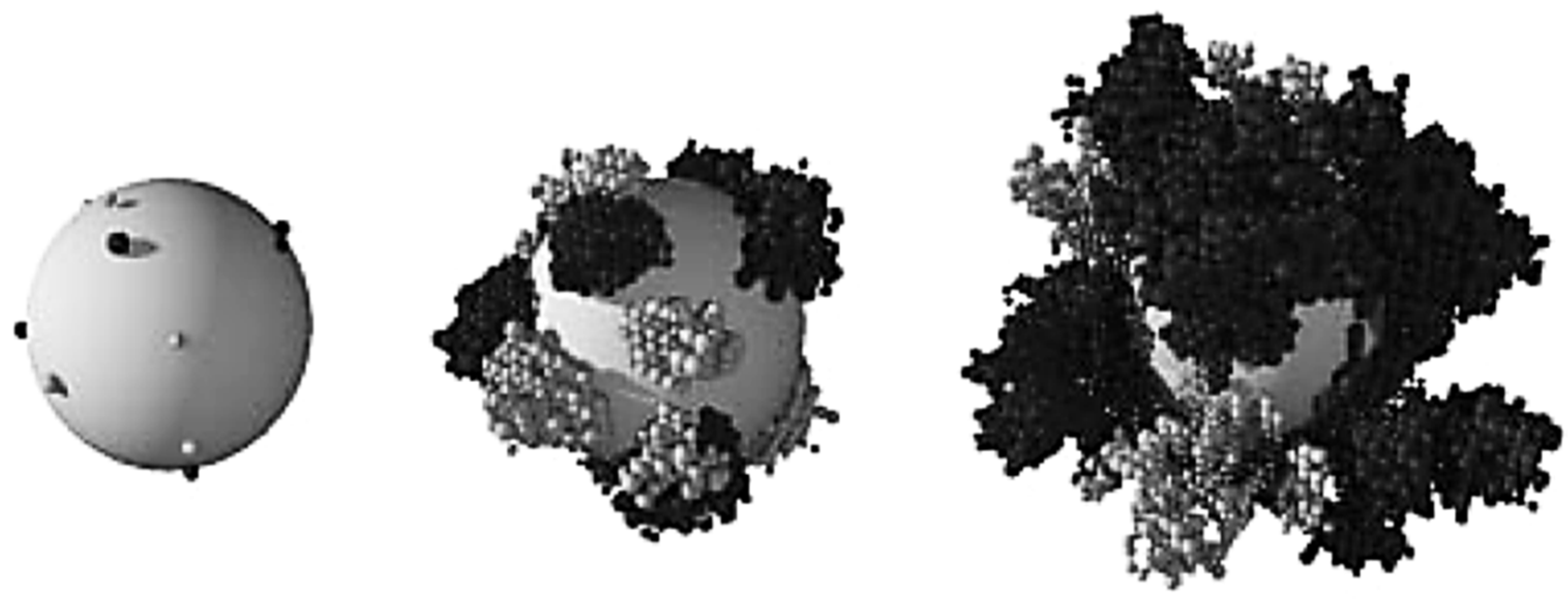
LBM-based models are more recent in time in the biofilm modeling research than others using FDM or FVM. A summary of all LBM-CA based models is shown in Table 2. It is common that CA is discretized spatially as same grid of rectangular elements as LBM. Each grid element has four first-order neighbors and another four second-order neighbors in the 2D square space discretization. A grid cell is allowed to be filled up to a predetermined maximum value and a simple rule is employed to locate the extra biomass in a new compartment. As one of the first studies in the file of biofilm growth using LBM-CA, Picioreanu et al. [35,37] presented a two- and three-dimensional model for biofilm growth considering both convective and diffusive mass transfer and cellular automata approach for the growth calculation. A two- and three-dimensional solute transport were solved using LBM when convection term was considered, or the FDM if without convection term. A CA approach was used for the biofilm growth calculation. This platform simulated bacterial growth, biomass spreading and biofilm detachment for multispecies and multi substrate biofilms. Figure 7 shows their simulated two-species biofilm growth on a spherical carrier. Their results showed that the LBM platform is a useful tool for multidimensional biofilm modeling.
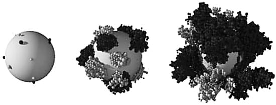
Figure 7.
A two-species biofilm simulated growth during time grown on a spherical carrier. Two bacteria are shown as dark and light-colored balls (Reprinted from [35] with permission from the copyright holders, IWA Publishing).
Biofilm growth in porous media has many important applications, such as, bioremediation of contaminated sites, bio-barriers development in groundwater protection, biodegradation, microbially-enhanced oil recovery, dynamic membrane filters and biofilters of wastewater treatment [21,28,40,41,66,67]. Due to the highly heterogeneous biofilm growth within porous media, this can cause a decrease of pore space, leading to a reduction in porosity and permeability of the system and increasing hydrodynamic depression. Therefore, understanding biofilm growth in porous media is of interests to achieve an efficiency of industrial applications matter.

Table 2.
Characteristics of LBM-CA based biofilm models.
Table 2.
Characteristics of LBM-CA based biofilm models.
| Ref. | Biofilm Growth | Dimension | Flow | Species | Temperature | pH | Consideration |
|---|---|---|---|---|---|---|---|
| Picioreanu et al. [35,37] | CA-Herbert-Pitt | 2D&3D | LBM | LBM | - | - | Reynolds number, Thiele number |
| Picioreanu et al. [48] | CA-Beeftink | 2D | LBM | LBM | - | - | |
| Picioreanu et al. [68] | CA-Beeftink | 2D | LBM | LBM | - | - | |
| Eberl et al. [34] | CA-Monod kinetics | 3D | LBM | HOC/CDS | - | - | |
| Knutson et al. [38] | CA-Dual Monod | 2D | LBM | Volume of Fluid Approach | - | - | |
| Knutson et al. [39] | CA-Dual Monod | 2D | LBM | Volume of Fluid Approach | - | - | |
| Tang et al. [69] | CA-Monod kinetics | 2D | LBM | Finite Difference Method | - | - | |
| Benioug et al. [70] | CA-Monod kinetics | 2D | LBM | Volume of Fluid Approach | - | - | Considering Damköhler and Péclet numbers and dimensionless shear stress |
| Benioug et al. [71] | CA-Monod and Haldane kinetics | 2D | LBM | Volume of Fluid Approach | - | - | Considering Damköhler and Péclet numbers and dimensionless shear stress |
| Delavar and Wang [3] | CA-Haldane and Monod Kinetics | 2D | LBM | LBM | - | - | Reynolds, Prandtl and Schmidt numbers and variable diffusion coefficient due to biofilm growth were considered. Variable properties and source term due to the local temperature and/or concentration change. Modified boundary conditions, shear stress calculation and extra biomass transfer. Considering variable properties. |
| Delavar and Wang [19] | CA | 2D | LBM | LBM | + | - | |
| Delavar and Wang [20] | CA | 2D | LBM | LBM | + | - | |
| Delavar and Wang [21] | CA | 2D | LBM | LBM | - | + | Including spatiotemporal effects of pH change due to inlet and local acid production and concentration on the bioprocess. |
Two-dimensional models were developed for simulations of fluid flow, substrate mass transfer, biomass growth and spreading around an irregular biofilm surface [48,68]. In their model, both diffusion and convection terms of the substrate mass transport were considered in the liquid phase and only diffusion term in the biofilm-gel matrix. They evaluated effects of convection and diffusion on biofilm heterogeneity under different mass transfer regimes. Their results showed that the maximum substrate flux to the biofilm was significantly affected by both internal and external mass transfer rates. However, it was observed that the inoculation density did not affect the maximum substrate flux to the biofilm. Eberl et al. [34] used LBM to simulate fluid flow using a combination of standard central difference scheme (CDS), high order compact (HOC) method for substrate concentration and CA for simulation of biofilm growth. They indicated that the solution algorithms were computationally expensive.
Knutson et al. [38,39] developed a hybrid model in which two-dimensional pore-scale LBM numerical model was used for flow field calculation, FVM for substrate transport and CA for biodegradation and biofilm growth. They simulated transvers mixing of species and biofilm growth within a 2D porous medium. Their results showed a qualitative agreement between numerical results and experimental ones. They also examined impact of some parameters, including reaction rate and biofilm shear strength, on biofilm growth and distribution in the domain. It was found that shear strength of new biomass and solute degradation rates are the most important factors that control biofilm growth.
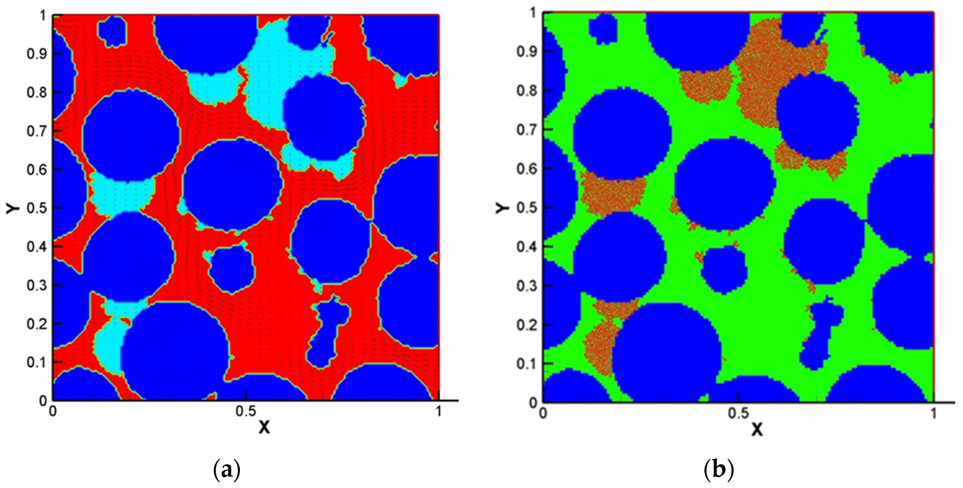
Tang et al. [69] developed a pore-scale biofilm model to study biofilm growth in porous media. LBM was used for simulations of fluid flow using lattice Boltzmann method, FDM for the concentration of species and CA for biofilm growth. They claimed that they have included the shrinkage procedure in biofilm growth for the first time. They found that an insufficient grid accuracy in the narrow liquid paths could cause about 90% reduction in computational time due to improvement of the numerical instability. Figure 8 shows their results for biofilm distribution in pore-space for both numerical and experimental investigations: (a) numerical and (b) experimental [69].

Figure 8.
Biofilm distribution in pore-space for both investigations: (a) numerical and (b) experimental (Reprinted from [69] with permission from John Wiley and Sons).
Benioug et al. [70] presented a two-dimensional LBM-CA pore scale numerical model to investigate biofilm growth in porous media. They simulated fluid flow using an immersed boundary LBM and substrate transport was captured using a volume of fluid type approach. They implemented a combined model of CA algorithm with immersed boundary methods to account for cell attachment and detachment mechanisms for the spreading and distribution of biomass in the two-dimensional domain. The dimensionless parameters, Damköhler and Péclet numbers and dimensionless shear stress, were used to describe biofilm growth effects on macroscopic properties of the porous media. Their results showed the capability of the coupled model to predict appropriately the interactions among fluid flow, species transport and bacterial growth under different hydrostatics and hydrodynamics conditions. Benioug et al. [71] examined the interaction between biofilm growth and non-aqueous-liquid (NAPL) dissolution/biodegradation in both abiotic and biotic conditions to assess the capability of the model. Although the FVM was used to solve solute transport in the domain, the fluid flow field was simulated using immersed boundary lattice Boltzmann method (IB-LB). Biomass growth was investigated using a CA which was same as their previous study [70]. Figure 9 shows the evolution of simulated biofilm growth on porous media [71]. They studied how the hydrodynamic regimes and spatial distribution of NAPL blobs affect the distribution rate under different blob size and Peclet numbers in abiotic conditions.

Figure 9.
Evolution of the transport processes and biofilm growth (coloured green) at Da =10 (Reprinted from [71] with permission from Elsevier).
In recent years, Delavar and Wang [3,19,20,21] perform a series of studies using LBM-CA to investigate impact of different working parameters and signals on microorganisms’ cooperation and competition with their industrial applications. Biofilms are mostly composed of multiple bacteria. As complex consortia of different microbial species, these species need to cooperate/compete with their neighbors for nutrient and space to survive. However, it is an imperative challenge to simulate the competition and the growth of multiple microorganisms in biofilms due to complex and multilateral interactions amid fluid, solid and bio-interfaces.
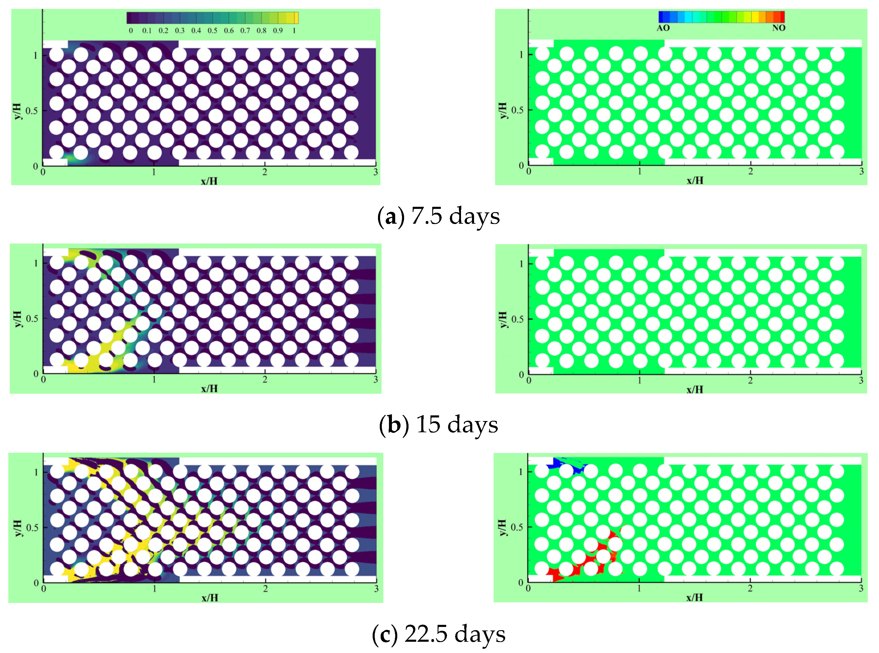
Due to the importance of the competitive growth, Delavar and Wang [3] investigated effects of aerobic nitrite and ammonium oxidizers in a micro bioreactor using an LBM-CA platform. If the biomass density in a lattice cell exceeds a maximum value, amount of the exceeded biomass is transferred to its neighboring grid cell. The selection of the new location is random or specific to find an appropriate neighbor. Unlike other LBM-CA models, if there are no empty neighbors, different spreading strategies were be applied by Delavar and Wang [3,19] to find a transfer direction of biomass according to concentration gradients. Newborn cells would be located to its neighbors with the maximum concentration gradient. The platform showed the ability to simulate bacterial growth, biomass spreading and biofilm detachment in multispecies and multi substrate biofilms. The effects of some parameters, such as the ratio of nutrient transfer rate to the biofilm and bacterial growth rate, were also investigated under different Reynolds number and Thiele modulus. Figure 10 shows biofilm concentration and aerobic nitrite and ammonium oxidizers bacteria in the microbioreactor at different simulation time. Their results revealed that the inlet nutrient concentrations had substantial effects on biofilm growth in terms of maximum biofilm concentration, microorganisms’ concentrations, growth pattern and time. This showed that the LBM-CA framework provides a powerful tool to improve our knowledge of dynamic multilateral behavior of many complex microbial consortia systems.
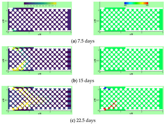

Figure 10.
Biofilm concentration (left) and cells occupied with aerobic nitrite oxidizer (red) or ammonium oxidizer (blue) at different simulation time: (a) 7.5 days, (b) 15 days, (c) 22.5 days and (d) 30 days (Reprinted from [3] with permission from John Wiley and Sons).
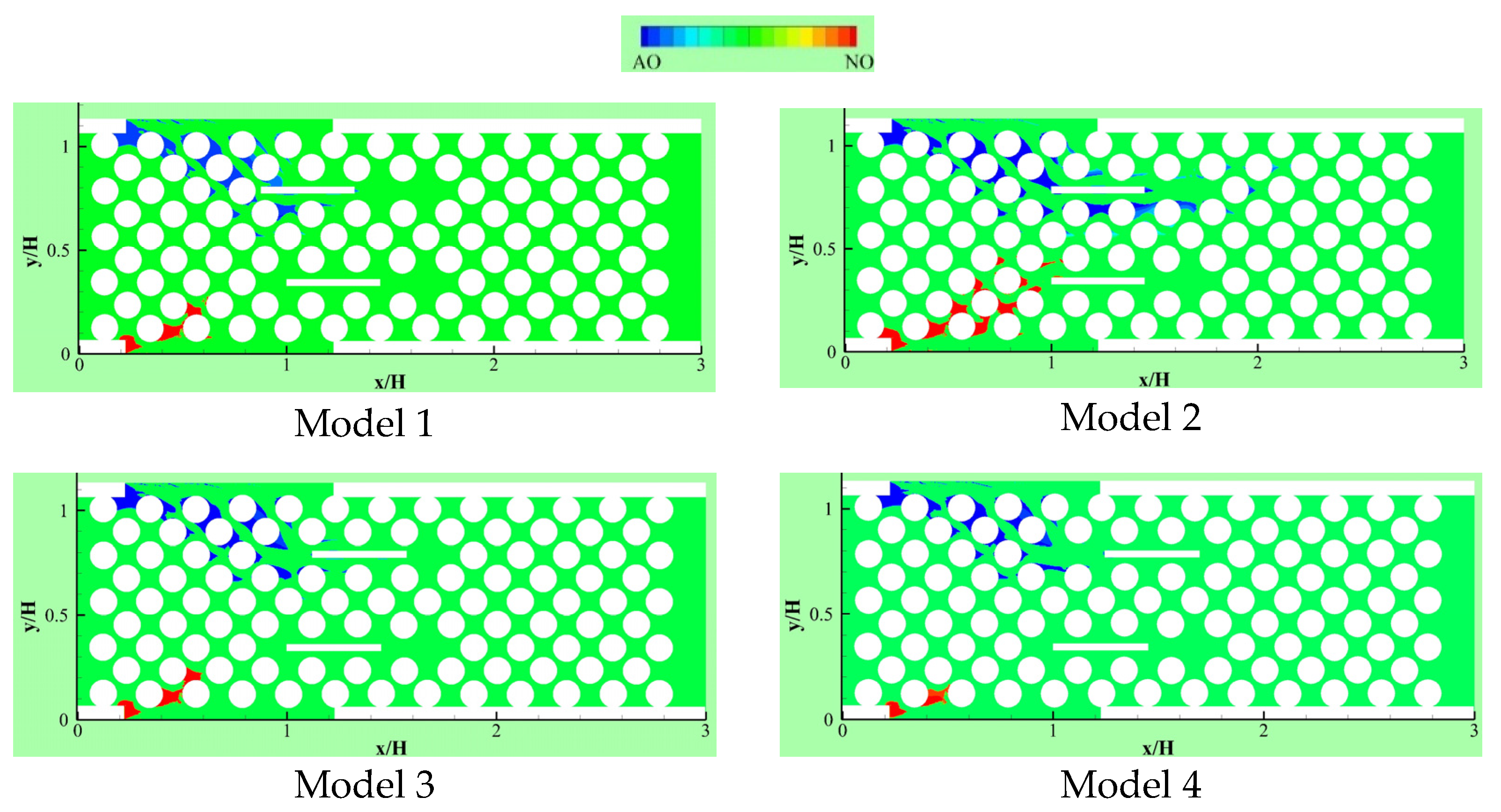
Delavar and Wang [19] developed their LBM-CA further to account for thermal effects on competitive biofilm growth in a microbioreactor. Two microbial species, aerobic nitrite and ammonium oxidizers, were considered in three geometrical configurations of the microbioreactor. Figure 11 illustrates aerobic nitrite oxidizer (red) and ammonium oxidizer (blue) patterns in different models in a reactor. In all geometries, two heating blocks were inserted to find and compare the impacts of changing structures and temperatures on competitive biofilm growth. It was observed that the heating blocks temperatures and locations had significant effects on both the biofilm growth rate and its pattern.
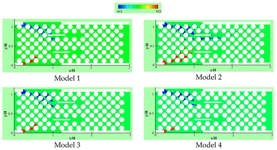
Figure 11.
Aerobic nitrite oxidizer (red) or ammonium oxidizer (blue) patterns in different places of heated blocks for the changed heating arrangement in the bioreactor (Reprinted from [19] with permission from American Chemical Society).
A detailed development of a thermal LBM-CA platform was presented with significant modifications in boundary condition implementation, variable properties, detachment and extra biomass transfer [20]. The effects of dimensionless number (e.g., Reynolds, Prandtl and Schmidt numbers) were analyzed. Their results showed that changing temperature has considerable effects on not only the biofilm growth rate but also the maximum biofilm concentration in the reactor. For example, it was observed that time to reach maximum concentration reduced to 5 days (high temperature case) from 30 days (low temperature case).
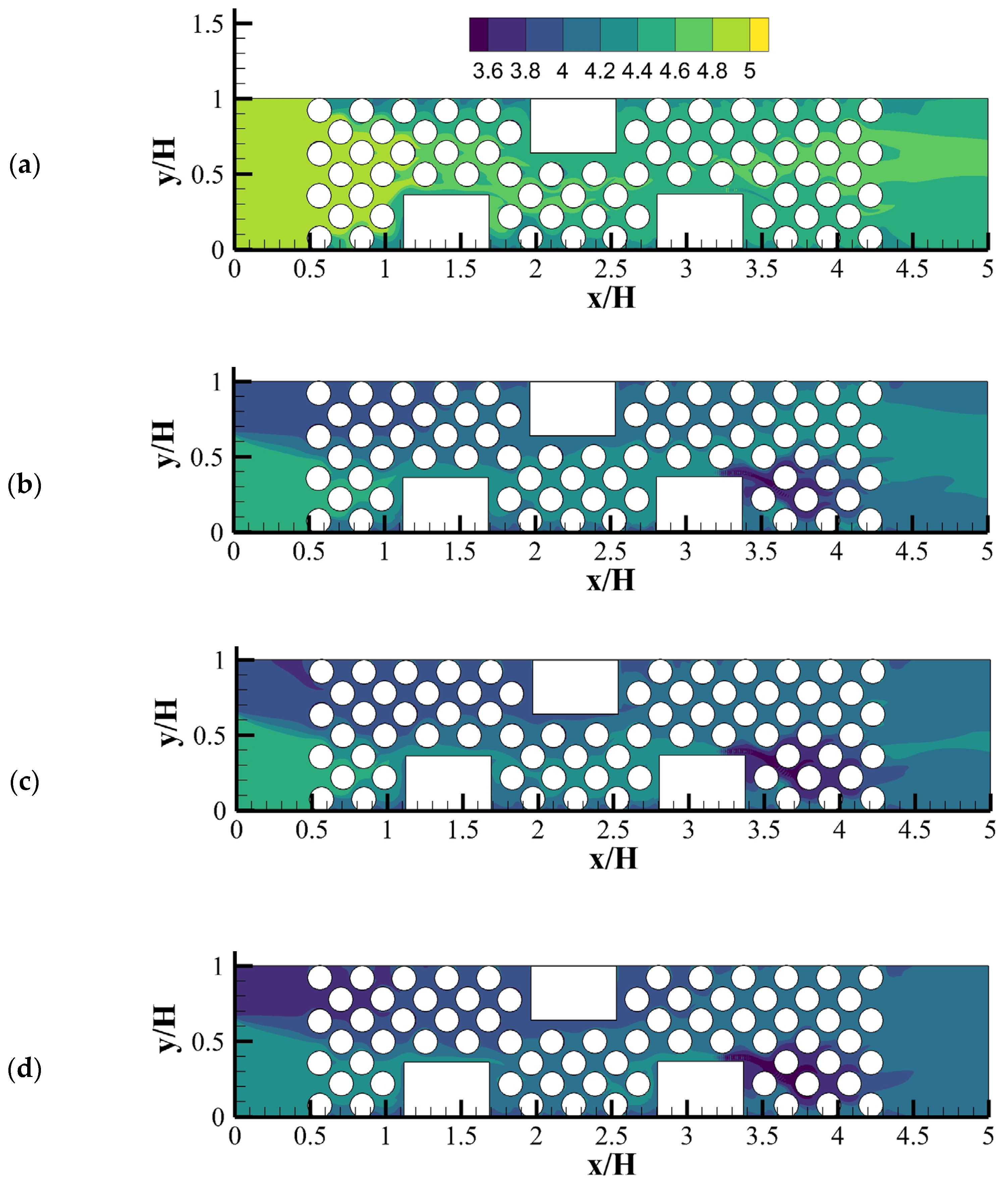
Delavar and Wang [21] developed an LBM-CA platform to account for fermentative biohydrogen production. The platform was successfully used to study dark fermentation in a microbioreactor. Figure 12 shows calculated pH contours in the microbioreactor at different acid concentration at inlet. Their results demonstrated that pH is one of signals affecting the performance of dark fermentation and. Acids are one of the main byproducts of many dark fermentation processes. A change of local acid production and inlet acid concentration could significantly affect local pH and dark fermentative biohydrogen production and extraction rates.
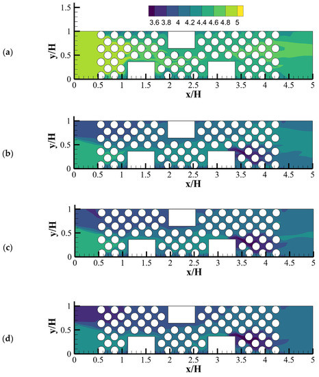
Figure 12.
pH contours for different inlet acetic acid concentration through Inlet 2 when pHi = 5: (a) Ci-2-acetic = 0, (b) Ci-2-acetic = 10, (c) Ci-2-acetic = 20 and (d) Ci-2-acetic = 30 (mole/m3) (Reprinted from [21] with permission from Elsevier).
3.3. LBM-IbM Based Biofilm Models
In LBM-IbM models, hydrodynamics, temperature and substrate transport are solved using LBM and biofilm growth, formation and detachment are simulated using IbM. Thus, LBM-IbM can account for large phenotypic heterogeneity in nature resulting from environmental differences. A summary of all LBM-IbM based models is shown in Table 3. LBM-IbM platforms have been used to study biofilm growth in different porous structures [44,72,73,74]. Graf von der Schulenburg et al. [44] developed a three-dimensional LBM-IbM model to examine multilateral interactions among fluid flow, nutrient mass transport and biofilm growth in porous media. Their results revealed that the permeability of porous media was highly affected by biofilm growth and showed the necessity of 3D simulations to capture more accurate results, compared to 2D models. Pintelon et al. [72] modified an LBM-IbM model to enable it to consider non-zero permeability of biofilms structures. They examined permeability reduction in porous medium due to the biofilm growth with a range of biofilm strengths. Their results showed that given stronger biofilms under constant pressure drop, less biomass deposition and energy input are required to reduce the system permeability. However, for weaker biofilms, it was observed that constant volumetric flow rate was more efficient to decline the permeability than constant pressure drop. This demonstrated that the significant influence of biofilm permeability on overall biofilm growth rate at large biofilm concentrations. Biofilm growth in sponge carrier media (which has a large surface area to volume ratio) was carried out by So et al. [74] using an LBM-IbM model. The simulated oxygen and biomass distributions inside both the porous network and biofilm were examined in mobbing bed biofilm reactors (MBBR). Their results showed that at low detachment rates more clogging happened in outer pores that limited biofilm growth on the surface region of the sponge.

Table 3.
Characteristics of LBM-IbM based biofilm models.
The fouling of biofilms in reverse osmosis (RO) membrane is one of the important issues in industrial production of high purity water. In good condition, RO membrane can remove 99% of mono- and divalent ions. However, biofilm growth can dwindle the fluid flow and system efficiency if biofilm fouling happens. Pintelon et al. [75] developed a 3D LBM-IbM model to simulate biofouling in the RO membrane. Monod kinetics was used for description of biofilm growth. Their simulated results agreed well with experimental data obtained with magnetic resonance imaging (MRI) techniques. They examined the effects of biofilm cohesive strength on the membrane pressure drop. It is found that weaker biomass has lower effects on pressure drop. Some cleaning strategies such as forward or backward flushing and electro-chemical treatment could be used to remove foulants, in RO membranes. Creber et al. [76] simulated membrane cleaning and reduction in the biofilm cohesive strength using an extension of LBM-IbM model proposed by Pintelon et al. [75]. They examined biofilm accumulation and chemical removal in RO membranes. The biofilm distribution and water flow field in the membrane, before and after cleaning, were captured. and their simulated biomass changes were in good agreement with experimental data.
In LBM-IbM models by Graf von der Schulenburg et al. [44], Pintelon et al. [72] and Pintelon et al. [73], the conventional LBGK was used to recover continuity and standard Navier–Stokes equations. Because Navier–Stokes equation is limited to simulate flows in porous media due to neglecting the variable porosity and permeability of unresolved microporosity in solid matrix and biofilms, the permeability of biofilm was considered indirectly through the manipulation of the LBGK relaxation parameter as the pseudo-viscosity for flow within biofilm-occupied simulation lattice. However, many porous materials, such as biofilms and soils, include multiscale pores or porosities that can contribute to the macro-permeability of porous media. Due to importance of the unresolved intra-aggregate pores in porous media, Tian and Wang [28] presented an LBM-IbM model which recovered the Darcy–Brinkman–Forchheimer equation. They used a multilayer bounce-back treatment developed by Tian and Wang [77] to account for multiscale porosities in biofilms and solid matrix. The coupled LBM-IbM model was implemented to study interactions among oxygen, bioclogging, chemical oxygen demand (COD), biofilm growth and multiscale permeability of the porous media and biofilms. Figure 13 shows the porosity distribution and velocity vectors and the biofilm colony distribution in the domain. Their results showed a very heterogeneous biofilm growth on the surface of the solid matrix and pores. In addition, they found a biofilm porosity threshold, beyond which no obvious effects on the flow rate and COD removal were observed. This demonstrated the capability of the model to study biofilm growth, clogging and contaminants degradation under various operational conditions in porous media. The model is potentially applicable to investigate processes in wastewater treatment.
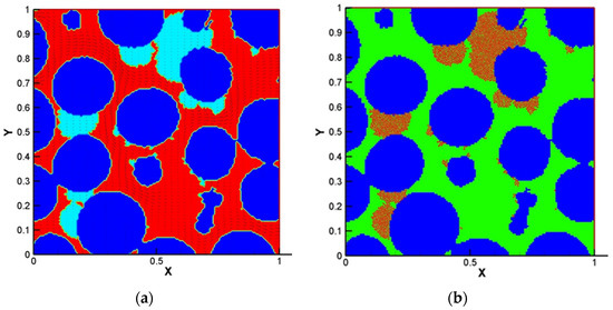
Figure 13.
(a) The porosity distribution and velocity vectors, (b) the biofilm colony distribution in the domain, at 38 × 104 time steps (Reprinted from [28] with permission from John Wiley and Sons).
4. Current Trends and Upcoming Challenges
LBM-based models are more recent in time in the biofilm modeling research than other biofilm models. Both LBM-CA and LBM-IbM approaches represent powerful tools in modeling biofilm growths. Compared to the FDM or FVM, as a meso-scale approach, LBMs coupled with IbM or CA have advantages to incorporate non-equilibrium interface processes and events and adopt distinct rules for cell spreading by different bacteria and, thus, can capture the micro-scale interactions among individual cells, local substrate variability and macroscopic structure of biofilms. Because geometries generated by computed x-ray tomography scan, such as porous media, can be directly inputted into LBM solver, this allows very complex geometries to be simulated [28]. Furthermore, because LBM solver uses two basic steps: stream and collision, this makes the code efficient and effective to be parallelized and implemented [57,78].
4.1. Advantages and Disadvantages of Different LBM-Based Models
The LBM-IbM model seems to be very appealing to microbiologists since it allows individual variability and tracks individual cells as the fundamental units [28,44]. The use of IbM would become necessary if the biofilm heterogeneity resulting from the intracellular interaction and their feedbacks between the individuals and the population needs to be simulated. In IbM, the collective action of individual cells reflects population or community level properties [79].
For LBM-CA model, a CA approach can use the same lattice grid as LBM. A set of rules is used for biomass spreading. As a CA grid is much bigger than an individual cell size, a CA grid is usually occupied by several cells. Therefore, CA does not resolve individual cells. Instead, CA uses a predetermined maximum biomass in a grid. Under the maximum biomass, biomass in the grid is represented by its percentage [3,19]. Any newborn cell in a grid is transferred to its neighbour grids in the biofilm front and the cell shoving with one another is not required.
Despite the aforementioned advantages, LBM-based models have disadvantages. First, because LBM-based models require to calculate distribution functions and then recover the macro variables, such as velocity, temperature and concentration, LBM-based models require more computer memory and computational time than FDM [57]. Particularly, LBM-IbM is very computationally intensive. Because IbM traces every individual cell and their interaction. Thus, at every time step, shoving and spreading of cells require many iterations to find appreciated position of every cell. The more the cell number, the more iterations will require. Thus, LBM-IbM models have been limited at small-scale systems. However, if the larger sizes of cells (e.g., 10 to 20 µm in diameter) or a parcel of cells are used, this will allow a larger system to be simulated while still keeping the shoving and spreading rules for cell redistribution. Furthermore, because individual cells are assumed as hard spheres and a predetermined shoving parameter is used to simulate the direction of the biomass movement. Constant biofilm porosity and the elastic contact between cells can also cause uncertainties.
In CA approach, spreading successfully movements are limited in a number of directions. The rules of spreading in CA are sometimes arbitrarily formulated. This might lead to it being aesthetically driven, rather than physically motivated [42].
4.2. Upcoming Challenges and Future Research Perspectives
Biofilm modeling is driven by the scientific and practical interest to understand, control and engineer biofilms in different applications, such as bioconversion, biofuel production, wastewater treatment and prevention of biofouling. With the impressive advances in genetic and biochemical technologies, it has been realized that the biofilms could not be defined as simply bacteria fastened to a hydrated surface. For example, antibiotic tolerance in biofilms causes the inability of antibiotic treatment in suppressing bacterial infections. Bacterial populations produce persisters that exhibit multidrug tolerance and survive treatment by all antimicrobials but the tolerance of persister cells is different from inherited, reversible antimicrobial resistance. Persister cells are greatly enhanced in biofilms. This can lead to difficulty to deal with biofilm-related diseases [80]. Quorum sensing involves perceiving and responding to extracellular signals of bacterial communities for competition and cooperation [81]. Furthermore, nutrient and microbial heterogeneity, quorum sensing and environmental conditions all affect the phenotypic distinctiveness of the individual stages of biofilm development. Individuals of the same species can clearly compete with each other, but they need cooperation in the multicellular-level. LBM-based models require to incorporate these features and behaviors of the complex biofilm communities as a possible way in controlling and removing biofilms of industrial and clinical concern [82].
Although IbMs have simulated signal transduction mechanisms in chemotaxis in the new field of synthetic biology [83] and the integration of intracellular mechanisms also enables the use of the rapidly increasing amount of metagenomic data, LBM-IbM or LBM-CA models have not been reported to simulate these complex features. It is still a challenge to account for different cells, such as active and inert cells, quorum sensing and antibiotics. Furthermore, biofilm models need to expand their capacities beyond the illustrative processes and simple geometries because many bioreactors are complex in industrial applications. However, simplification and parameterization of the general biofilm models are inevitable to achieve a specific goal in industrial applications. Therefore, a comprehensive model of biofilm reactors may not require including as many parameters as possible, but rather, to assess the level of significance of various parameters. This can make it feasible to capture the main features in the description of the different biofilm processes as the necessary data can be extracted for the reactor design and operation.
5. Conclusions
In this paper, we revisit a family of the LBM-based biofilm models chronologically. We present the fundamentals of LBM-based biofilm modeling first and two main integrated approaches: the integrated LBM with CA or IbM. Then, we focus on progresses of LBM-CA and LBM-IbM approaches and their applications. The LBM-based models are very promising to handle complex multilateral interactions which occur in a bioreactor and have successfully simulated many complicated phenomena in the biofilm’s dynamics and interactions between biofilm growth and hydrodynamics in different industrial or academic applications. However, long-term challenges exist in modeling biofilms when bridging different spatiotemporal scales, such as multispecies competition and cooperation, community assembly, cell-to-cell signaling, quorum sensing, antimicrobial resistance and cellular motility. Addressing these challenges would inevitably need a combined approach that not only selectively couples multiple relevant models by adding their strengths, but also the incorporation of new findings. LBM-based models doubtlessly offer new ways in understanding the dynamics of biofilms and controlling the biofilm formation and growth in public health, biotechnology and bioengineering and microbiology.
Author Contributions
Conceptualization, M.A.D. and J.W.; methodology, M.A.D.; formal analysis, M.A.D. and J.W.; data curation, M.A.D. and J.W.; writing—original draft preparation, M.A.D.; writing—review and editing, M.A.D. and J.W.; supervision, J.W.; project administration, J.W.; funding acquisition, J.W. All authors have read and agreed to the published version of the manuscript.
Funding
This work was supported by Natural Sciences and Engineering Research Council (No. RGPIN-2019-07071).
Institutional Review Board Statement
Not applicable.
Informed Consent Statement
Not applicable.
Conflicts of Interest
The authors declare no conflict of interest.
References
- Flemming, H.C.; Wingender, J.; Szewzyk, U.; Steinberg, P.; Rice, S.A.; Kjelleberg, S. Biofilms: An emergent form of bacterial life. Nat. Rev. Microbiol. 2016, 14, 563–575. [Google Scholar] [CrossRef] [PubMed]
- Gunes, B. A critical review on biofilm-based reactor systems for enhanced syngas fermentation processes. Renew. Sustain. Energy Rev. 2021, 143, 110950. [Google Scholar] [CrossRef]
- Delavar, M.A.; Wang, J. Pore-scale modeling of competition and cooperation of multispecies biofilms for nutrients in changing environments. AIChE J. 2020, 66, e16919. [Google Scholar]
- Wong, A.C.L. Biofilms in food processing environments. J. Dairy Sci. 1998, 81, 2765–2770. [Google Scholar] [CrossRef]
- Alvarez-Ordóñez, A.; Coughlan, L.M.; Briandet, R.; Cotter, P.D. Biofilms in food processing environments: Challenges and opportunities. Annu. Rev. Food Sci. Technol. 2019, 10, 173–195. [Google Scholar] [CrossRef]
- Zhao, X.; Zhao, F.; Wang, J.; Zhong, N. Biofilm formation and control strategies of foodborne pathogens: Food safety perspectives. RSC Adv. 2017, 7, 36670–36683. [Google Scholar] [CrossRef]
- Xu, Z.; Wang, J.; Xia, L.; Zhang, Y. A biofouling thermal resistance model with a growth term of surface biofilm on heat transfer surface. Int. J. Therm. Sci. 2021, 161, 106699. [Google Scholar] [CrossRef]
- de Vries, H.J.; Kleibusch, E.; Hermes, G.D.; van den Brink, P.; Plugge, C.M. Biofouling control: The impact of biofilm dispersal and membrane flushing. Water Res. 2021, 198, 117163. [Google Scholar] [CrossRef]
- Akao, P.K.; Singh, B.; Kaur, P.; Sor, A.; Avni, A.; Dhir, A.; Verma, S.; Kapoor, S.; Phutela, U.G.; Satpute, S.; et al. Coupled microalgal–bacterial biofilm for enhanced wastewater treatment without energy investment. J. Water Process Eng. 2021, 41, 102029. [Google Scholar] [CrossRef]
- Mallikarjuna, C.; Dash, R.R. A review on hydrodynamic parameters and biofilm characteristics of inverse fluidized bed bioreactors for treating industrial wastewater. J. Environ. Chem. Eng. 2020, 8, 104233. [Google Scholar] [CrossRef]
- di Biase, A.; Kowalski, M.S.; Devlin, T.R.; Oleszkiewicz, J.A. Moving bed biofilm reactor technology in municipal wastewater treatment: A review. J. Environ. Manag. 2019, 247, 849–866. [Google Scholar] [CrossRef]
- Swain, A.K.; Sahoo, A.; Jena, H.M.; Patra, H. Industrial wastewater treatment by aerobic inverse fluidized bed biofilm reactors (AIFBBRs): A review. J. Water Process Eng. 2018, 23, 61–74. [Google Scholar] [CrossRef]
- Obileke, K.; Onyeaka, H.; Meyer, E.L.; Nwokolo, N. Microbial fuel cells, a renewable energy technology for bio-electricity generation: A mini-review. Electrochem. Commun. 2021, 125, 107003. [Google Scholar] [CrossRef]
- Saravanan, A.; Kumar, P.S.; Vardhan, K.H.; Jeevanantham, S.; Karishma, S.B.; Yaashikaa, P.R.; Vellaichamy, P. A review on systematic approach for microbial enhanced oil recovery technologies: Opportunities and challenges. J. Clean. Prod. 2020, 258, 120777. [Google Scholar] [CrossRef]
- Gaol, C.L.; Ganzer, L.; Mukherjee, S.; Alkan, H. Parameters govern microbial enhanced oil recovery (MEOR) performance in real-structure micromodels. J. Pet. Sci. Eng. 2021, 205, 108814. [Google Scholar] [CrossRef]
- Roy, P.K.; Ha, A.J.W.; Mizan, M.F.R.; Hossain, M.I.; Ashrafudoulla, M.; Toushik, S.H.; Nahar, S.; Kim, Y.K.; Ha, S.D. Effects of Environmental Conditions (temperature, pH, and glucose) on Biofilm Formation of Salmonella enterica serotype Kentucky and Virulence Gene Expression. Poult. Sci. 2021, 100, 101209. [Google Scholar] [CrossRef]
- Kim, W.J.; Kim, S.H.; Kang, D.H. Thermal and non-thermal treatment effects on Staphylococcus aureus biofilms formed at different temperatures and maturation periods. Food Res. Int. 2020, 137, 109432. [Google Scholar] [CrossRef] [PubMed]
- Shojaei, B.; Khazaee, I. 1-D transient microbial fuel cell simulation considering biofilm growth and temperature variation. Int. J. Therm. Sci. 2021, 162, 106801. [Google Scholar] [CrossRef]
- Delavar, M.A.; Wang, J. Modeling combined effects of temperature and structure on competition and growth of multispecies biofilms in microbioreactors. Ind. Eng. Chem. Res. 2020, 59, 16122–16135. [Google Scholar] [CrossRef]
- Delavar, M.A.; Wang, J. Modeling coupled temperature and transport effects on biofilm growth using thermal lattice Boltzmann model. AIChE J. 2021, 67, e17122. [Google Scholar] [CrossRef]
- Delavar, M.A.; Wang, J. Numerical investigation of pH control on dark fermentation and hydrogen production in a microbioreactor. Fuel 2021, 292, 120355. [Google Scholar] [CrossRef]
- Matheus, M.C.; Ekenberg, M.; Bassin, J.P.; Dezotti, M.W.; Piculell, M. High loaded moving bed biofilm reactors treating pulp & paper industry wastewater: Effect of hydraulic retention time, filling degree and nutrients availability on performance, biomass fractions and nutrients utilization. J. Environ. Chem. Eng. 2021, 9, 104944. [Google Scholar]
- Chaiwong, C.; Koottatep, T.; Polprasert, C. Development of kinetic models for organic and nutrient removal in biofilm photobioreactor for treatment of domestic wastewater. Environ. Technol. Innov. 2021, 23, 101547. [Google Scholar] [CrossRef]
- Chen, X.; Chen, X.; Zhao, Y.; Zhou, H.; Xiong, X.; Wu, C. Effects of microplastic biofilms on nutrient cycling in simulated freshwater systems. Sci. Total Environ. 2020, 719, 137276. [Google Scholar] [CrossRef]
- Iltis, G.C.; Armstrong, R.T.; Jansik, D.P.; Wood, B.D.; Wildenschild, D. Imaging biofilm architecture within porous media using synchrotron-based X-ray computed microtomography. Water Resour. Res. 2011, 47, W02601. [Google Scholar] [CrossRef]
- Zhang, Y.; Xu, A.; Lv, X.; Wang, Q.; Feng, C.; Lin, J. Non-Invasive Measurement, Mathematical Simulation and In Situ Detection of Biofilm Evolution in Porous Media: A Review. Appl. Sci. 2021, 11, 1391. [Google Scholar] [CrossRef]
- Mattei, M.R.; Frunzo, L.; D’Acunto, B.; Pechaud, Y.; Pirozzi, F.; Esposito, G. Continuum and discrete approach in modeling biofilm development and structure: A review. J. Math. Biol. 2018, 76, 945–1003. [Google Scholar] [CrossRef]
- Tian, Z.; Wang, J. Lattice Boltzmann simulation of biofilm clogging and chemical oxygen demand removal in porous media. AIChE J. 2019, 65, e16661. [Google Scholar] [CrossRef]
- Williamson, K.; McCarty, P. A model of substrate utilization by bacterial films. J. Water Pollut. Control Fed. 1976, 48, 9–24. [Google Scholar]
- Harremoes, P. The significance of pore diffusion to filter denitrification. J. Water Pollut. Control Fed. 1976, 48, 377–388. [Google Scholar]
- Wanner, O.; Gujer, W. A multispecies biofilm model. Biotechnol. Bioeng. 1986, 28, 314–328. [Google Scholar] [CrossRef]
- Laspidou, C.S.; Kungolos, A.; Samaras, P. Cellular-automata and individual-based approaches for the modeling of biofilm structures: Pros and cons. Desalination 2010, 250, 390–394. [Google Scholar] [CrossRef]
- Picioreanu, C.; van Loosdrecht, M.C.M.; Heijnen, J.J. Mathematical modeling of biofilm structure with a hybrid differential-discrete cellular automaton approach. Biotechnol. Bioeng. 1998, 58, 101–116. [Google Scholar] [CrossRef]
- Eberl, H.; Picioreanu, C.; van Loosdrecht, M. Modeling geometrical heterogeneity in biofilms. In High Performance Computing Systems and Applications; Pollard, A., Mewhort, D.J.K., Weaver, D.F., Eds.; Springer: Boston, MA, USA, 2002; pp. 497–512. [Google Scholar]
- Picioreanu, C.; van Loosdrecht, M.; Heijnen, J. Discrete-Differential modelling of biofilm structure. Water Sci. Technol. 1999, 59, 115–122. [Google Scholar] [CrossRef]
- Noguera, D.R.; Pizarro, G.; Stahl, D.A.; Rittmann, B.E. Simulation of multispecies biofilm development in three dimensions. Water Sci. Technol. 1999, 39, 123–130. [Google Scholar] [CrossRef]
- Picioreanu, C.; van Loosdrecht, M.; Heijnen, J. Multidimensional Modeling of Biofilm Structure. In Microbial Biosystems: New Frontiers; Bell, C.R., Brylinsky, M., Johnson-Green, P., Eds.; Atlantic Canada Society for Microbial Ecology: Halifax, NS, Canada, 1999. [Google Scholar]
- Knutson, C.; Werth, C.J.; Valocchi, A.J.; Travis, B.J. Modeling biofilm morphology along a transverse mixing zone in porous media at the pore scale. In Developments in Water Science; Miller, C.T., Farthing, M.W., Gray, W.G., Pinder, G.F., Eds.; Elsevier: Amsterdam, The Netherlands, 2004; Volume 55, pp. 61–69. [Google Scholar]
- Knutson, C.E.; Werth, C.J.; Valocchi, A.J. Pore-scale simulation of biomass growth along the transverse mixing zone of a model two-dimensional porous medium. Water Resour. Res. 2005, 41, W07007. [Google Scholar] [CrossRef]
- Singh, R.; Paul, D.; Jain, R.K. Biofilms: Implications in bioremediation. Trends Microbiol. 2006, 14, 389–397. [Google Scholar] [CrossRef] [PubMed]
- Seo, Y.; Lee, W.H.; Sorial, G.; Bishop, P.L. The application of a mulch biofilm barrier for surfactant enhanced polycyclic aromatic hydrocarbon bioremediation. Environ. Pollut. 2009, 157, 95–101. [Google Scholar] [CrossRef] [PubMed]
- Eberl, H.J.; Parker, D.F.; van Loosdrecht, M.C.M. A new deterministic spatio-temporal continuum model for biofilm development. J. Theor. Med. 2001, 3, 161–175. [Google Scholar] [CrossRef]
- Picioreanu, C.; Kreft, J.U.; van Loosdrecht, M.C.M. Particle-Based multidimensional multispecies biofilm model. Appl. Environ. Microbiol. 2004, 70, 3024–3040. [Google Scholar] [CrossRef]
- Graf von der Schulenburg, D.A.; Pintelon, T.R.R.; Picioreanu, C.; Van Loosdrecht, M.C.M.; Johns, M.L. Three-dimensional simulations of biofilm growth in porous media. AIChE J. 2009, 55, 494–504. [Google Scholar] [CrossRef]
- Picioreanu, C.; van Loosdrecht, M. Use of mathematical modelling to study biofilm development and morphology. In Biofilms in Medicine, Industry and Environmental Biotechnology: Characteristics, Analysis and Control; Lens, P., Moran, A.P., Mahony, T., Stoodley, P., O’Flaherty, V., Eds.; IWA Publishing: London, UK, 2003; pp. 413–437. [Google Scholar]
- Donlan, R.M. Biofilms: Microbial Life on Surfaces. Emerg. Infect. Dis. 2002, 8, 881–890. [Google Scholar] [CrossRef]
- Kapellos, G.E.; Alexiou, T.S.; Payatakes, A.C. A multiscale theoretical model for diffusive mass transfer in cellular biological media. Math. Biosci. 2007, 210, 177–237. [Google Scholar] [CrossRef]
- Picioreanu, C.; Van Loosdrecht, M.C.; Heijnen, J.J. Effect of diffusive and convective substrate transport on biofilm structure formation: A two-dimensional modeling study. Biotechnol. Bioeng. 2000, 69, 504–515. [Google Scholar] [CrossRef]
- Kreft, J.U.; Booth, G.; Wimpenny, J.W.T. BacSim, a simulator for individual-based modelling of bacterial colony growth. Microbiology 1998, 144, 3275–3287. [Google Scholar] [CrossRef]
- Frisch, U.; d’Humieres, D.; Hasslacher, B.; Lallemand, P.; Pomeau, Y.; Rivet, J.P. Lattice gas hydrodynamics in two and three dimensions. Complex Syst. 1987, 1, 649–707. [Google Scholar]
- Bhatnagar, P.L.; Gross, E.P.; Krook, M. A model for collision processes in gases. I. Small amplitude processes in charged and neutral one-component systems. Phys. Rev. 1954, 94, 511. [Google Scholar] [CrossRef]
- Qian, Y.H.; d’Humières, D.; Lallemand, P. Lattice BGK models for Navier-Stokes equation. EPL Europhys. Lett. 1992, 17, 479. [Google Scholar] [CrossRef]
- Chen, H.; Chen, S.; Matthaeus, W.H. Recovery of the Navier-Stokes equations using a lattice-gas Boltzmann method. Phys. Rev. A 1992, 45, R5339. [Google Scholar] [CrossRef]
- Mohamad, A.A. Fundamentals and Engineering Applications with Computer Codes; Springer: London, UK, 2011. [Google Scholar]
- Raabe, D. Overview of the lattice Boltzmann method for nano-and microscale fluid dynamics in materials science and engineering. Model. Simul. Mater. Sci. Eng. 2004, 12, R13. [Google Scholar] [CrossRef]
- Chen, S.; Doolen, G.D. Lattice Boltzmann method for fluid flows. Annu. Rev. Fluid Mech. 1998, 30, 329–364. [Google Scholar] [CrossRef]
- Wang, J.; Zhang, X.; Bengough, A.G.; Crawford, J.W. Domain-decomposition method for parallel lattice Boltzmann simulation of incompressible flow in porous media. Phys. Rev. E 2005, 72, 016706. [Google Scholar] [CrossRef] [PubMed]
- Mezrhab, A.; Jami, M.; Abid, C.; Bouzidi, M.H.; Lallemand, P. Lattice-Boltzmann modelling of natural convection in an inclined square enclosure with partitions attached to its cold wall. Int. J. Heat Fluid Flow 2006, 27, 456–465. [Google Scholar] [CrossRef]
- Delavar, M.A.; Farhadi, M.; Sedighi, K. Numerical simulation of direct methanol fuel cells using lattice Boltzmann method. Int. J. Hydrogen Energy 2010, 35, 9306–9317. [Google Scholar] [CrossRef]
- Ajarostaghi, S.S.M.; Delavar, M.A.; Poncet, S. Thermal mixing, cooling and entropy generation in a micromixer with a porous zone by the lattice Boltzmann method. J. Therm. Anal. Calorim. 2019, 140, 1–19. [Google Scholar] [CrossRef]
- Graf von der Schulenburg, D.A.; Gladden, L.F.; Johns, M.L. Modelling biofilm-modified hydrodynamics in 3D. Water Sci. Technol. 2007, 55, 275–281. [Google Scholar] [CrossRef]
- Zhang, C.; Kang, Q.; Wang, X.; Zilles, J.L.; Müller, R.H.; Werth, C.J. Effects of pore-scale heterogeneity and transverse mixing on bacterial growth in porous media. Environ. Sci. Technol. 2010, 44, 3085–3092. [Google Scholar] [CrossRef]
- Yang, Y.; Liao, Q.; Zhu, X.; Wang, H.; Wu, R.; Lee, D.J. Lattice Boltzmann simulation of substrate flow past a cylinder with PSB biofilm for bio-hydrogen production. Int. J. Hydrogen Energy 2011, 36, 14031–14040. [Google Scholar] [CrossRef]
- Liao, Q.; Yang, Y.X.; Zhu, X.; Chen, R.; Fu, Q. Pore-scale lattice Boltzmann simulation of flow and mass transfer in bioreactor with an immobilized granule for biohydrogen production. Sci. Bull. 2017, 62, 22–30. [Google Scholar] [CrossRef]
- Liao, Q.; Yang, Y.X.; Zhu, X.; Chen, R.; Fu, Q. A simulation on flow and mass transfer in a packed bed photobioreactor for hydrogen production. Int. J. Heat Mass Transf. 2017, 109, 1132–1142. [Google Scholar] [CrossRef]
- Al-Bader, D.; Kansour, M.K.; Rayan, R.; Radwan, S.S. Biofilm comprising phototrophic, diazotrophic, and hydrocarbon-utilizing bacteria: A promising consortium in the bioremediation of aquatic hydrocarbon pollutants. Environ. Sci. Pollut. Res. 2013, 20, 3252–3262. [Google Scholar] [CrossRef]
- Huang, T.; Xu, J.; Cai, D. Efficiency of active barriers attaching biofilm as sediment capping to eliminate the internal nitrogen in eutrophic lake and canal. J. Environ. Sci. 2011, 23, 738–743. [Google Scholar] [CrossRef]
- Picioreanu, C.; Van Loosdrecht, M.C.; Heijnen, J.J. Two-dimensional model of biofilm detachment caused by internal stress from liquid flow. Biotechnol. Bioeng. 2001, 72, 205–218. [Google Scholar] [CrossRef]
- Tang, Y.; Valocchi, A.J.; Werth, C.J.; Liu, H. An improved pore-scale biofilm model and comparison with a microfluidic flow cell experiment. Water Resour. Res. 2013, 49, 8370–8382. [Google Scholar] [CrossRef]
- Benioug, M.; Golfier, F.; Oltéan, C.; Buès, M.A.; Bahar, T.; Cuny, J. An immersed boundary-lattice Boltzmann model for biofilm growth in porous media. Adv. Water Resour. 2017, 107, 65–82. [Google Scholar] [CrossRef]
- Benioug, M.; Golfier, F.; Fischer, P.; Oltean, C.; Buès, M.A.; Yang, X. Interaction between biofilm growth and NAPL remediation: A pore-scale study. Adv. Water Resour. 2019, 125, 82–97. [Google Scholar] [CrossRef]
- Pintelon, T.R.; Graf von der Schulenburg, D.A.G.; Johns, M.L. Towards optimum permeability reduction in porous media using biofilm growth simulations. Biotechnol. Bioeng. 2009, 103, 767–779. [Google Scholar] [CrossRef] [PubMed]
- Pintelon, T.R.; Picioreanu, C.; van Loosdrecht, M.C.; Johns, M.L. The effect of biofilm permeability on bio-clogging of porous media. Biotechnol. Bioeng. 2012, 109, 1031–1042. [Google Scholar] [CrossRef] [PubMed]
- So, M.; Naka, D.; Goel, R.; Terashima, M.; Yasui, H. Modelling clogging and biofilm detachment in sponge carrier media. Water Sci. Technol. 2014, 69, 1298–1303. [Google Scholar] [CrossRef] [PubMed][Green Version]
- Pintelon, T.R.; Creber, S.A.; Graf von der Schulenburg, D.A.G.; Johns, M.L. Validation of 3D simulations of reverse osmosis membrane biofouling. Biotechnol. Bioeng. 2010, 106, 677–689. [Google Scholar] [CrossRef]
- Creber, S.A.; Pintelon, T.R.R.; Von Der Schulenburg, D.G.; Vrouwenvelder, J.S.; Van Loosdrecht, M.C.M.; Johns, M.L. Magnetic resonance imaging and 3D simulation studies of biofilm accumulation and cleaning on reverse osmosis membranes. Food Bioprod. Process. 2010, 88, 401–408. [Google Scholar] [CrossRef]
- Tian, Z.; Wang, J. Lattice Boltzmann simulation of CO2 reactive transport in network fractured media. Water Resour. Res. 2017, 53, 7366–7381. [Google Scholar] [CrossRef]
- Wang, J.; Zhang, X.; Bengough, A.G.; Crawford, J.W. Performance evaluation of the cell-based algorithms for domain decomposition in flow simulation. Int. J. Numer. Methods Heat Fluid Flow 2008, 18, 656–672. [Google Scholar] [CrossRef]
- Hellweger, R.L.; Clegg, R.J.; Clark, J.R.; Plugge, C.M.; Kreft, J.U. Advancing microbial sciences by individual-based modelling. Nat. Rev. Microbiol. 2016, 14, 461–471. [Google Scholar] [CrossRef]
- Brauner, A.; Fridman, O.; Gefen, O.; Balaban, N.Q. Distinguishing between resistance, tolerance and persistence to antibiotic treatment. Nat. Rev. Microbiol. 2016, 14, 320–330. [Google Scholar] [CrossRef]
- Dalwadi, M.P.; Pearce, P. Emergent robustness of bacterial quorum sensing in fluid flow. Proc. Natl. Acad. Sci. USA 2021, 118, e2022312118. [Google Scholar] [CrossRef]
- Cogan, N.G.; Harro, J.M.; Stoodley, P.; Shirtliff, M.E. Predictive computer models for biofilm detachment properties in pseudomonas aeruginosa. mBio 2016, 7, e00815-16. [Google Scholar] [CrossRef] [PubMed]
- Emonet, T.; Cluzel, P. Relationship between cellular response and behavioral variability in bacterial chemotaxis. Proc. Natl. Acad. Sci. USA 2008, 105, 3304–3309. [Google Scholar] [CrossRef] [PubMed]
Publisher’s Note: MDPI stays neutral with regard to jurisdictional claims in published maps and institutional affiliations. |
© 2021 by the authors. Licensee MDPI, Basel, Switzerland. This article is an open access article distributed under the terms and conditions of the Creative Commons Attribution (CC BY) license (https://creativecommons.org/licenses/by/4.0/).

