Article

Numerical Analysis and Parametric Study of a 7 kW Tubular Permanent Magnet Linear Alternator

by
Chin-Hsiang Cheng
1,* and
Surender Dhanasekaran
2
1
Department of Aeronautics and Astronautics, National Cheng Kung University, Tainan City 70101, Taiwan
2
International Doctoral Degree Program on Energy Engineering, National Cheng Kung University, Tainan City 70101, Taiwan
*
Author to whom correspondence should be addressed.
Sustainability 2021, 13(13), 7192; https://doi.org/10.3390/su13137192
Submission received: 14 May 2021 / Revised: 22 June 2021 / Accepted: 22 June 2021 / Published: 26 June 2021
(This article belongs to the Special Issue Advances in Renewable Energy Technologies for Distributed Generation)

Abstract

:
Free-Piston Stirling Engines (FPSEs) are known for their easy maintenance, longer lifetimes, high reliability, quiet operation due to no crankshafts, and having fewer seals compared to the traditional Stirling engine. Free-piston systems are popular in the conversion of thermal energy into electrical energy and are compatible with many types of heat sources. This research paper concentrates on the development of a Permanent Magnet Linear Alternator (PMLA) and parametrically analyzing it to predict its limitations and performance over variable operable conditions and material choices. Operable conditions including stroke length and frequency of the translator, and material choice for the stator and magnets, are varied in this study to analyze the machine and put it to test for its extreme limitations. Spacing between slots is introduced to reduce the overall mass of the stator and increase the power density. The load test is carried out with varied parameters. It induces a load EMF of 2.4 kV, yields a power of 7 kW, and has a power density of 314 W/kg by FEM analysis in peak variations. This study enumerates the performance variation of a PMLA over these varied conditions and illustrates the limitations of such power-dense machines.

1. Introduction

Global warming has been continuously rising in recent years and will continue to grow if no necessary actions are taken. Sustainable growth meeting the global demands for power production and reduction in greenhouse gas emissions should be brought under control by 2030 or catastrophic disasters will happen with irreversible consequences. Limiting the global temperature rise within 1.5 °C could slow down this process and make way for sustainable growth [1]. The demand for global energy supply has been consistently rising in the recent past. Environmental pollution has been a major concern over the conventional method of power production, and researchers across the globe are continuously working on perfecting green energy technology to reduce pollution and find alternative methods of energy harvesting techniques in the power production sector. Conventional modes of power production have mostly used rotational motion. Oscillatory motion power sources have been converted to rotary motion ones for power production before the familiarity with linear generators, which resulted in acute mechanical power losses. The perk of a linear alternator is reversible; it can be used as an actuator for multiple applications which requires two machines to start and continue to produce power [2]. In the recent past, linear electric actuators and generators have become popular in domains such as FPSE, wave energy harvesting, hybrid electric vehicles, and sub-domaining applications such as waste heat recovery, concentrated solar power, and space applications [3,4,5,6].
Stirling engines have been advancing in the past 50 years and have been widely used in solar energy harvesting. Having a temperature as low as 300 °C, Stirling engines are even used in waste heat recovery systems in industries for power production with only several watts [7]. A waste heat recovery system is used to pump the heat to be used as an additional source to the prime movers such as thermoacoustic engines and FPSEs [8,9]. NASA has been consistently developing free-piston energy systems continuously for space applications. A 12.5 kW electrical output with piston displacement of 14 mm at 70 Hz and a 6 kW electrical output with piston displacement of 16 mm at 60 Hz were developed in the years 1999 and 2010, respectively, by NASA’s Stirling space engine programs in multiple phases [10,11].
Linear alternators are categorized based on topology, phase, and type of mover. By topology, PMLAs are categorized into flat and tubular types; by phase, they are categorized into single and three-phase; by type of mover, they are categorized as moving magnet, moving iron, and moving coil [12]. Linear crankless internal combustion engines with only one moving part with a compact structure, higher efficiency, and reliability for remote power production applications integrate PMLAs in one linear system [13]. In a similar system, the PMLAs are used in the power generation to be used as an auxiliary power unit for a Hybrid Electric Vehicle (HEV) [14]. These integrated systems are used as range extenders in the HEVs apart from the main driving mechanism [15].
Wave energy is another key application of linear alternators. The fundamental difference observed in the applications of PMLAs in wave energy harvesting and combustion (internal and external) engines from a bird’s-eye view is Wave Energy Converters (WECs), which have a long stroke length and low frequency, and combustion inputs have a smaller stroke length and a higher frequency [4,13]. However, the construction and operation features of both of the alternator applications are different. WECs are power-dense machines ranging from a few to several hundred kilowatts of electrical power deliverability [16]. Their stroke lengths are about hundred times that of combustion applications. Continuous research is conducted on this front to reach sustainable growth and generalize this source of power.
Recent developments in the research and manufacturing abilities of rare-earth magnets have provided the possibility to pack multiple combinations of NdFeB magnets for various utilizations [17], especially extending the demagnetization temperature to a maximum of 180 °C for special applications [18]. The Quasi-Halbach (QH) magnetization pattern of arranging the magnets creates a rotating pattern of magnetization. For the tubular PMLAs, the strong and weak sides of the arrangement are decided based on the application and type of the mover [19]. Axial and radial array magnets are placed depending on the number of strong and weak sections required by the specific application that the PMLA is designed for.
In the constructional arrangement of the stator in a PMLA, the stator can be divided into multiple segments for structural independence. A tubular PMLA has a single coil accommodated in a 12-segment split stator or a flat-type PMLA with 18 coils accommodated in a four-segment squared-off stator to ensure structural independence and is applied in different applications [20,21,22]. Similarly, slotless generators are becoming popular for their high efficiency and negligible cogging force on the translator [23]. However, the flux linkage on the stator is minimal, and thus a lower EMF is induced in the coil. Several modifications are made to the permanent magnet to give satisfactory results. The utilization of the QH array over axial magnets proves to be more efficient in slotless generators [24].
In a free-piston linear system simulation, the integration of thermodynamic, dynamic, and electromagnetic models is necessary to predict the behavior of the system in the real-time working state. For operating the system at its full efficient state, a parametric study of the PMLA is necessary to understand the ability to work in a stable engine operation state [24]. For post-parametric analysis on FEA software, before the integration of the PMLA onto an engine, an experimental set-up is set to test the ability to match the numerical analysis results [25,26]. A rotary motor is set to operate at the operating frequency of the PMLA. Cogging force is a locking mechanism acting on the translator due to the magnetic field of the permanent magnet with the stator [27]. Cogging force is responsible for the noise and vibration created on the translator and causes excessive maintenance for the PMLA. Several techniques are used in the reduction in the cogging force, mostly by altering the shape of the magnet [28]. Using these techniques, the cogging force is reduced by 40%, also affecting the performance of the PMLA. These techniques are used on radial and axial magnets. Due to the utilization of a Soft Magnetic Composite (SMC) in most PMLAs, the eddy-current losses are negligible even by using a solid core [29]. Having considered all the constraints from the limitations of having a lighter machine to operate at a higher frequency, the overall mass of the machine should be reduced to have a higher specific power. Hence, the volume of the machine should be reduced to attain a higher efficient state of the PMLA [30]. The induced EMF is not readily usable and requires a control system to manage the starting and operation of the integrated system [31].
Linear alternators are designed and executed in different applications. However, their limitations are not tested or shown. Considering a proven alternator design [5], a few changes were made to the design to test the limitations of the PMLA numerically on a commercial software JMAG® Designer V18. To test these limitations, four parametric changes are made in this study. The specific power is one important parameter to be considered for remote applications such as space applications. By increasing the number of turns in a coil and reducing the overall mass of the stator, the specific power is boosted.

2. PMLA Design

Due to the structural merits, the tubular type of linear alternator is more reliable than the flat-type [3]. The alternator design considered in this paper is an adaptation from a conventional model [5]. In convergence with the research aim, the stator of the PMLA was redesigned to accommodate a greater number of turns than the original model. For the design changes, firstly, the back iron thickness was reduced by 30% from the original dimensions. Secondly, slot spaces were included between the poles. The original design consisting of a five-pole arrangement was retained to not make any major change including the outer diameter and stack length of the stator and the air gap between the translator and the stator. By making these two major changes, the slot became wider and deeper. The introduction of the slot space reduced the mass of the stator from 15.055 kg to 7.6 kg—a 50% reduction in the overall mass of the stator. This resulted in accommodating more coil turns per slot, which raised from 2024 turns to 2990 turns per slot—a 30% raise per slot. According to Faraday’s law (1), the induced electromotive force (e) is directly dependent on the number of coil turns (N) and the magnetic flux (ϕ) linked to the coil.
e = N d ϕ d t
The geometrical design data of the altered model presented in this research are mentioned in Table 1. The complete PMLA structure considered for the simulation is shown in Figure 1. The stacking factor of the stator is kept at 96% for the stator and the translator shaft is prescribed by the manufacturer of laminated steel. The mass of each part of PMLA is mentioned in Table 2. The overall mass of the PMLA is 22.7 kg.

3. Baseline Case

The PMLA is assigned with fixed conditions for a baseline case. The baseline cases for the variable parameters are mentioned in Table 3. To ensure the continuity of the translator movement, a ten-cycle simulation has been carried out and found to have a stable movement over the period. Due to the QH array magnet arrangement, the strong and weak sections of the array form a uniform distribution of magnetic flux density (Figure 2a) in the stator. The flux line (Figure 2b) is uniformly distributed around the stator; the mark is kept at 10 mm from the start of the stator stack to understand the flow in the first slot.
The baseline case is run in an open-circuit condition. Figure 3 shows the transient variations of no-load voltage and displacement (D) for two cycles. A peak open-circuit voltage Voc of 3052 V and RMS voltage of 2052 V was obtained at the displacement dead point. A sinusoidal representation of the induced EMF such as the displacement profile is observed.
This slotted PMLA has a QH array; therefore, there is no compromise on performance and no-load cogging force (Cn), with a similar profile to the displacement exerted on the translator, which further reduces the vibration on the translator, bringing stability to the machine. This profile is observed throughout the parametric variations made. For the baseline case, a peak cogging force of 1568 N is induced on the translator which can be observed in Figure 4.

4. Parametric Study

The PMLA consists of several physical parameters and conditions to be assigned for the numerical analysis to be conducted, out of which, few parameters cannot be changed due to the direct influence they hold with the geometrical dimensions, thus changing the original design. However, the operating conditions assigned to the translator are the frequency and stroke length in the electromagnetic simulation. The choice of materials assigned for the PMLA can be varied to study the behavior change and to choose the best case for the PMLA. Predominantly, the system consists of three major components: stator, coil, and the translator (shaft and magnets). The material choice for the coil is insulated copper and cannot be varied. The choice of magnet and stator material was chosen based on the previous research carried out by our research group [32]. The numerical simulations were carried out subject to the understanding of epistemic uncertainties and were assumed to be in near-perfect condition [33,34].

5. Results and Discussion

All simulations were carried out with a purely resistive load of 1000 Ω. Due to the utilization of the SMC core, there is a negligible value of eddy-current losses. Hence, eddy-current losses were neglected from the study for all the variations made. All representations of Power (Pl), voltage (Vl), and cogging force (Cl) are Root Mean Square (RMS) values in the parametric study results.

5.1. Effects of Frequency

Frequency is one of the operating conditions assigned for the simulation. It was varied in steps of 10 from 10 Hz to 100 Hz. All other parameters were set in the baseline case to maintain uniformity. Figure 5 represents the plot between the induced power versus the varied frequency. A linear rise was seen over a course until 60 Hz. After 60 Hz, saturation was observed in the curve. Since most engines operate in this range from 60 Hz to 100 Hz, it was deemed reasonable to stop at this level and this PMLA also agrees with this range [3]. It is analogous that the induced EMF has a similar profile to the power; Figure 6 shows the induced EMF for the frequency variation.
The cogging force on the translator is constant after 10 Hz. There is a steep rise in the cogging force from 10 Hz to 20 Hz. Figure 7 represents the influence of frequency change in cogging force on the translator. From 20 Hz to 100 Hz, there is a near-constant force with minute variations from 674 N to 681 N.

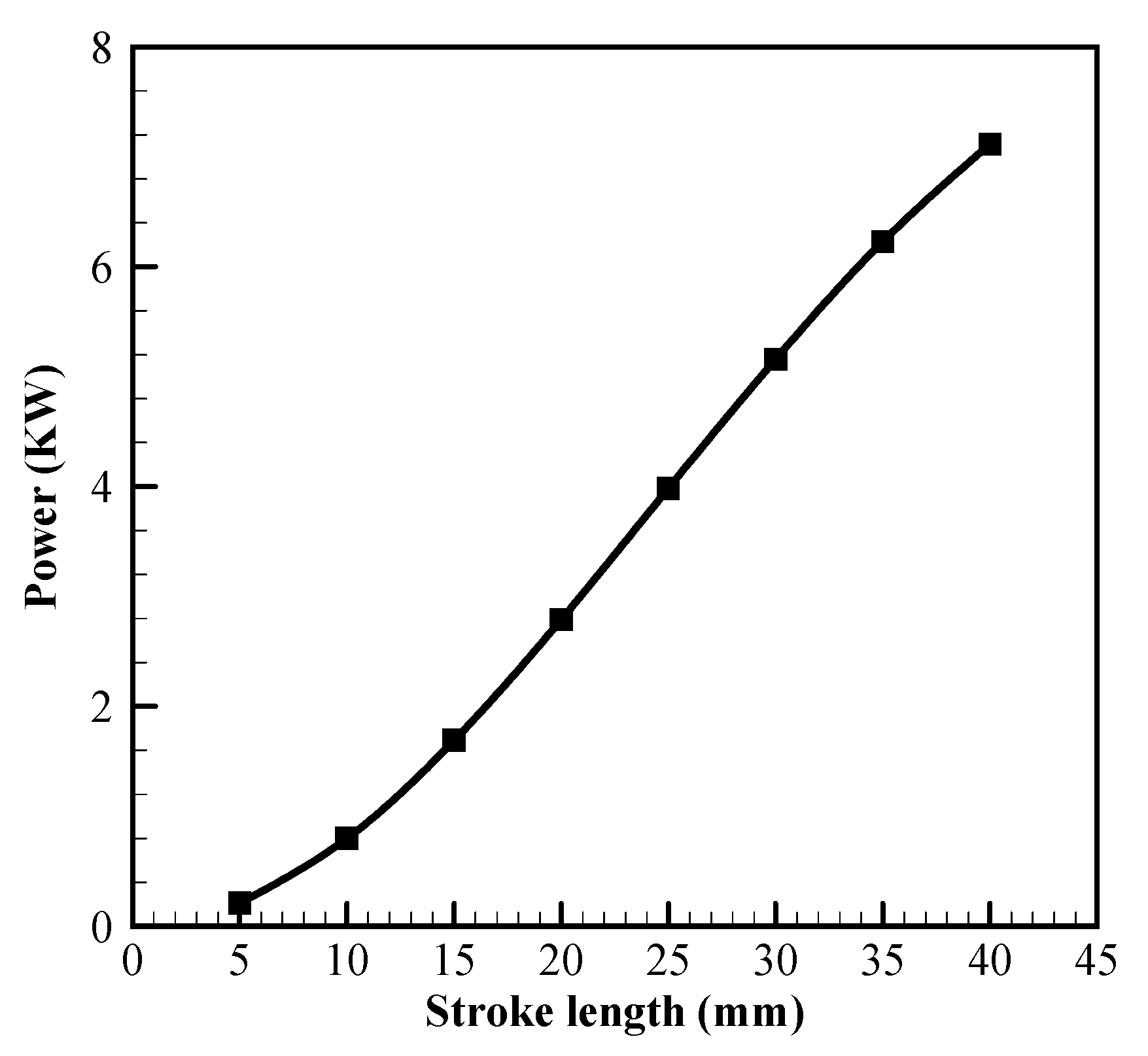
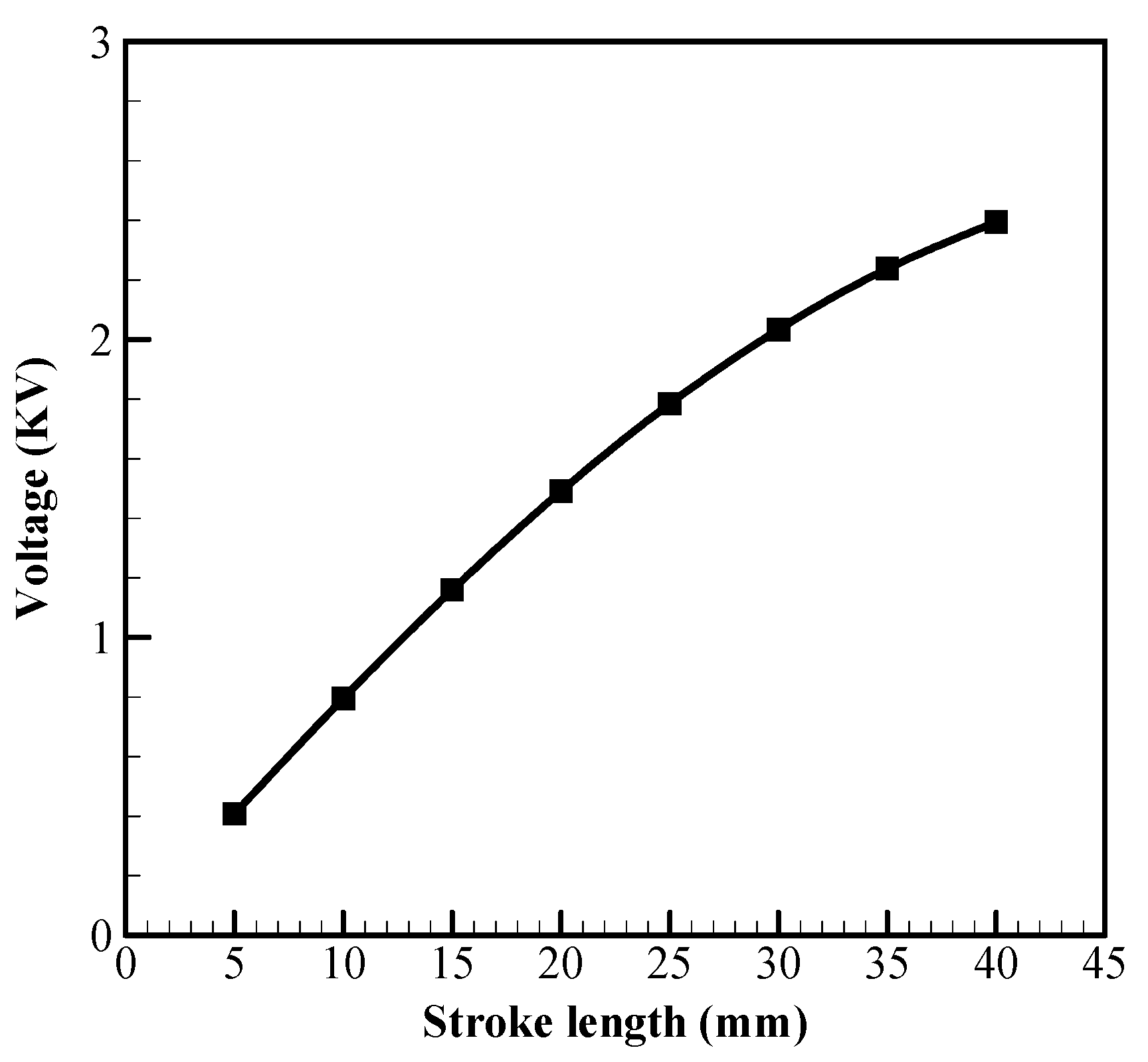
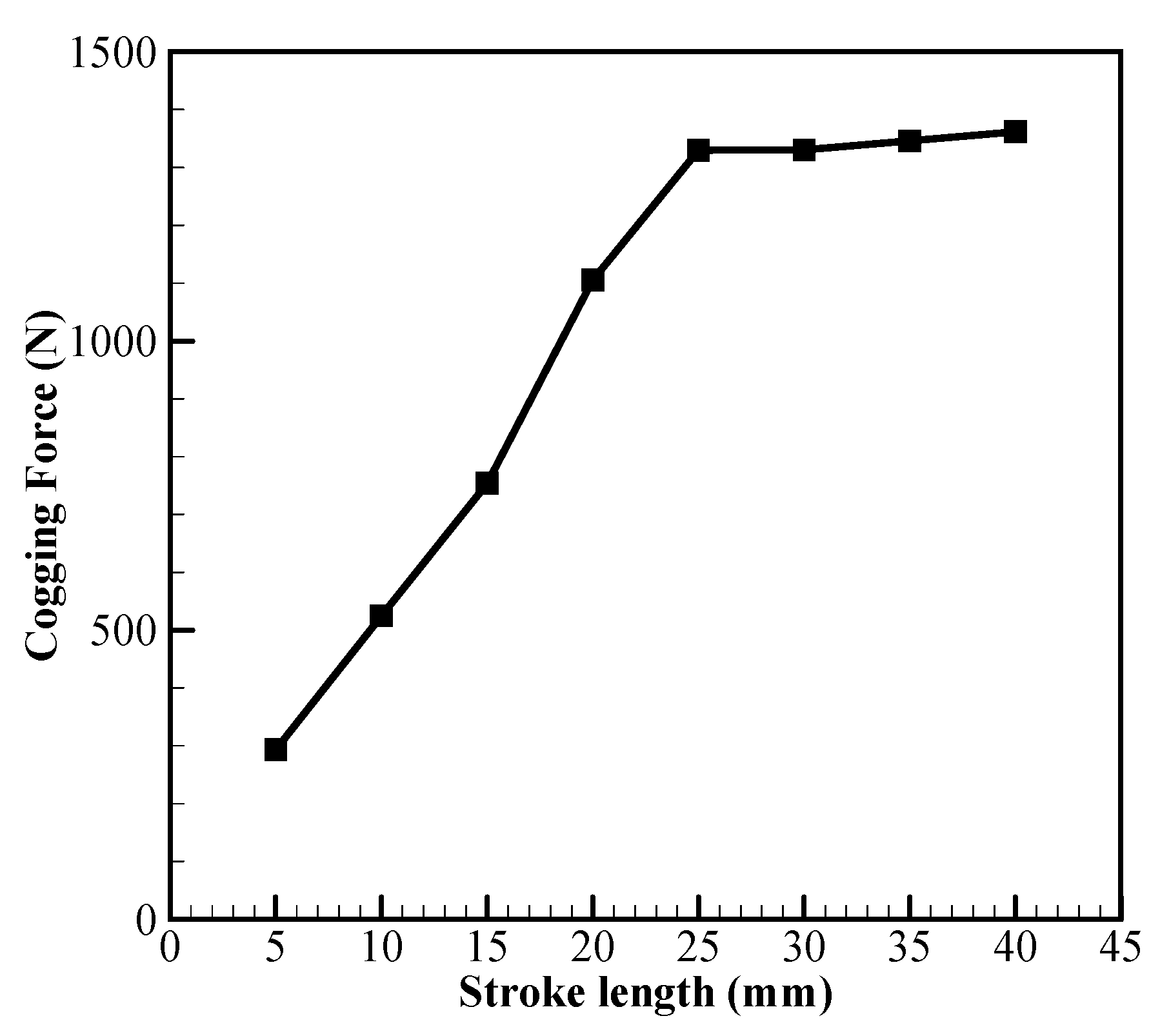
5.2. Effects of Stroke Length

Stroke length is another operating condition assigned for the simulation. The movement of the translator from the top dead point to the bottom dead point is considered here as one complete stroke. This stroke length was varied from 5 mm to 40 mm in 5 mm increments. The influence of stroke length is strong on induced power. Figure 8 represents the influence of stroke length on power induced on the load. There is a linear growth in the power with the rise in stroke length. Due to the limitation of the design, it was limited to a 40 mm stroke for this analysis. The power induced on the resistive load varied from 210 W for a 5 mm stroke to 7116 W for a 40 mm one. A wide band of power deliverability is available for the stroke variation. Similarly, the induced load voltage, from the influence of stroke length, has the same profile as power, shown in Figure 9. The induced load voltage varied from 408 V to 2395 V the stroke varied from 5 mm to 40 mm.
The cogging force has a linear elevation in Figure 10 due to a change in stroke length and attains saturation after 25 mm. This saturation is similar to the frequency variation from 20 Hz to 100 Hz. This level of saturation leaves a choice to operate the machine without a strong influence of the cogging force after a 25 mm stroke for an application that requires more power.

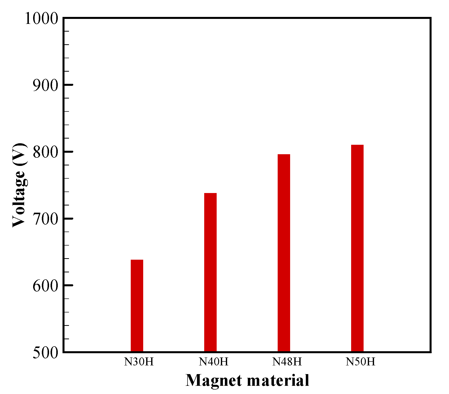
5.3. Effects of Magnet Material

Using NXXH magnets for their higher demagnetization temperature. For the case of magnet material variation, N30H, N40H, N48H, and N50H were considered. The influence of magnet material change on power and cogging force is represented in Figure 11. There was a change in induced power from 514 W to 826 W due to the magnetic material change. Similarly, the cogging force varied from 338 N to 542 N. However, the similarity of the profile between the power and cogging force was uniform throughout the material change. It is evident that the induced power comes with a similar cogging force, and they are proportional to each other. This similarity is found in the induced load voltage in Figure 12. Hence, choosing the right magnetic material for a specific application and maximum cogging force handling ability should be in equilibrium.

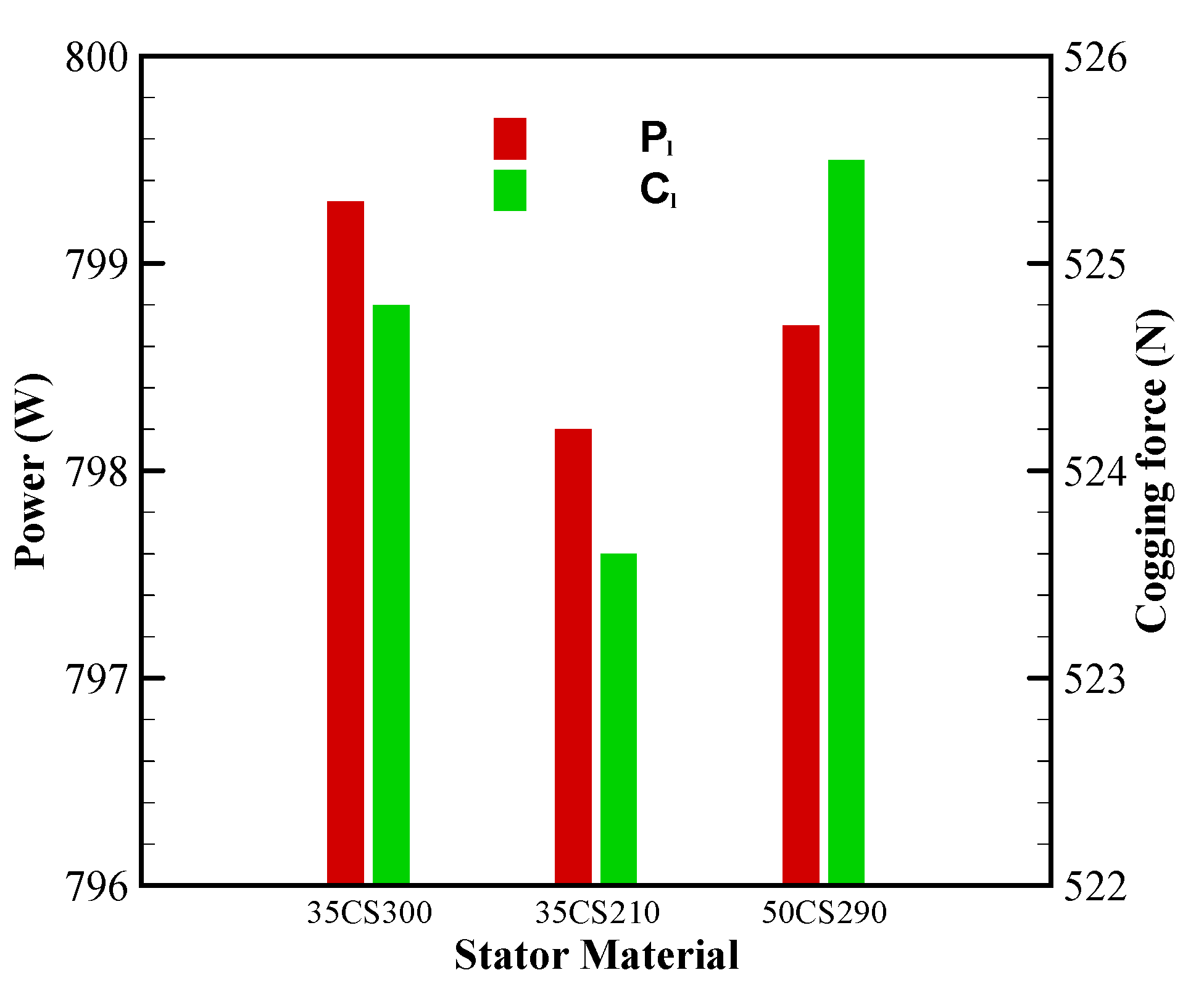
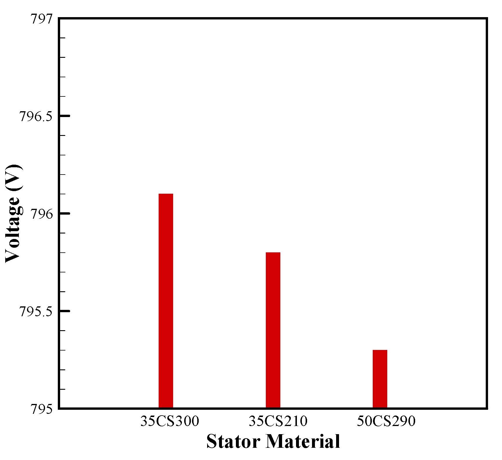
5.4. Effects of Stator Material
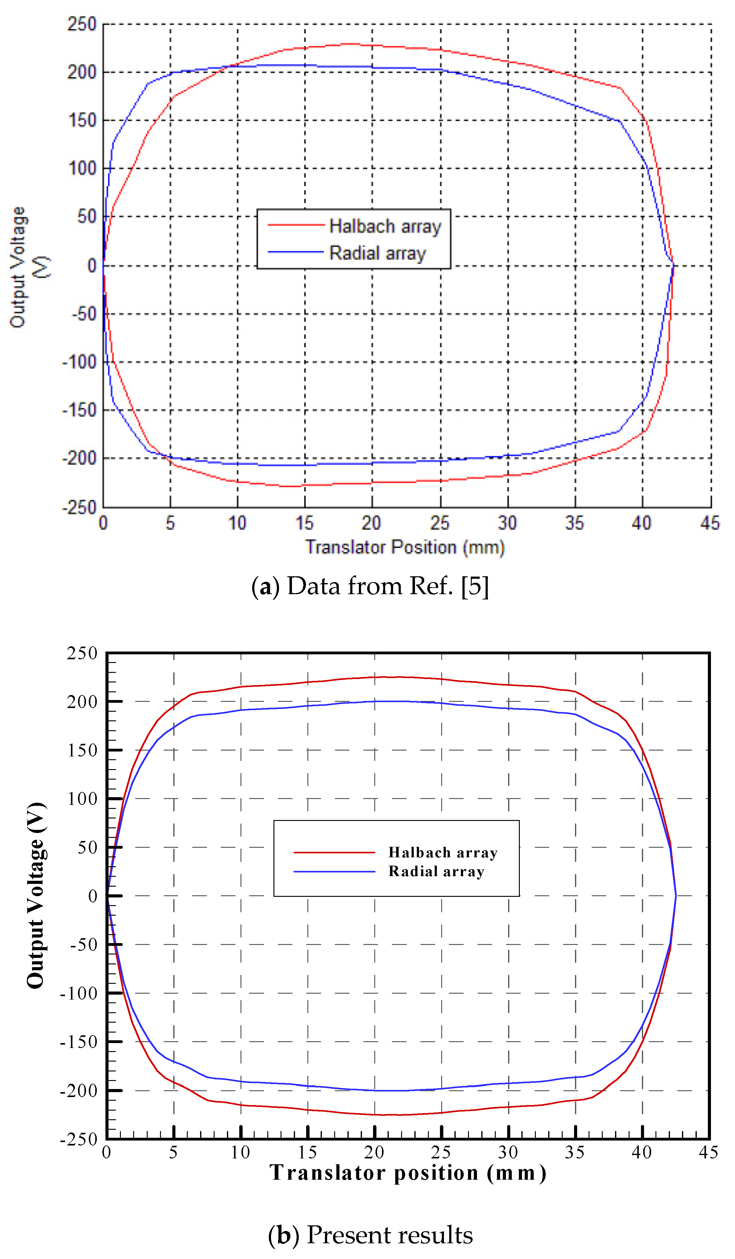
Electrical steel for the stator and translator shaft was chosen from the same material combination for the variation. Three different materials—35CS300, 35CS210 and 50CS290—were selected for this comparison. The 35 and 50 series material varied with the thickness of the sheet metal: 0.35 mm and 0.5 mm for 35 and 50 series materials. Additionally, the density of the material varies with thickness. Since there is a limitation of stacking factor for the sheet metals at 96% for all the materials from China Steel, consideration of denser materials was avoided for this comparison. The influence of a change in stator material on Pl and Cl is not significant enough, though, in comparison to the profiles of Pl and Cl, the 35 series steel has a better ratio than the 50 series steel seen in Figure 13. Similarly, the 35 series has a better Vl induction capability than the 50 series steel. This comparative analysis can be seen in Figure 14.

6. Validation

To validate the current results from the FEA simulation of the derived model, the original model is designed and simulated assigning the original conditions from Ref. [5]. Figure 15 represents the comparison between the results from the paper (Figure 15a) and FEA simulation results (Figure 15b) carried out for validation purposes. The impacts of translator position on induced voltage for the Halbach array and radial array are compared from the experimental results of Behrooz Rezaeealam [5]. In comparison to the original results from Figure 15a, the simulated results from Figure 15b have similar profiles at a maximum displacement of 42.5 mm. Peak voltages of 230 V and 205 V were obtained in Halbach and radial array configurations, respectively, are seen from Ref. [5]. These peak voltages of 225 V and 200 V were also obtained for the two configurations by the present simulation. Although a small variation of overlap is found in the data from Ref. [5], this is not seen in the present results due to ideal conditions. Hence, there is a reasonable agreement between the present and existing results.
To further understand the advantage gained with the present model to achieve a higher performance than the existing model considered in Ref. [5], an analysis was executed at 21.27 Hz and 42.5 mm stroke for the Halbach array with 16.67 Ω as the load resistance. The results obtained from this analysis in comparison with the existing model are represented in Table 4 to show the relative performance of the present PMLA. In this table, data not provided are indicated with ‘-’. It is seen that by using the present model, one is able to achieve both higher power and higher voltage by properly modifying the design parameters.

7. Conclusions

The developed model introduces a slot space between slots to reduce the use of excess material to achieve a higher specific power than the existing model. Adapted by proven models, the design modifications were found to be improved in the baseline case consideration. The major findings are summarized as follows:
(1)
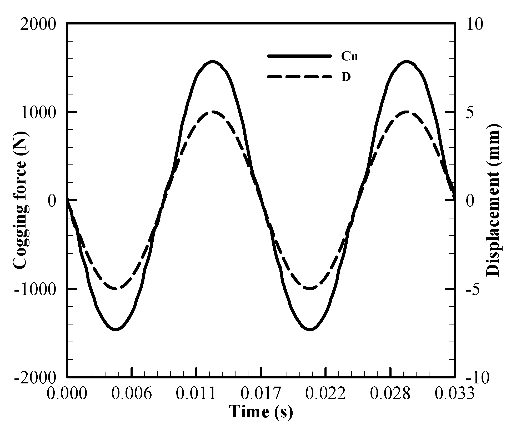
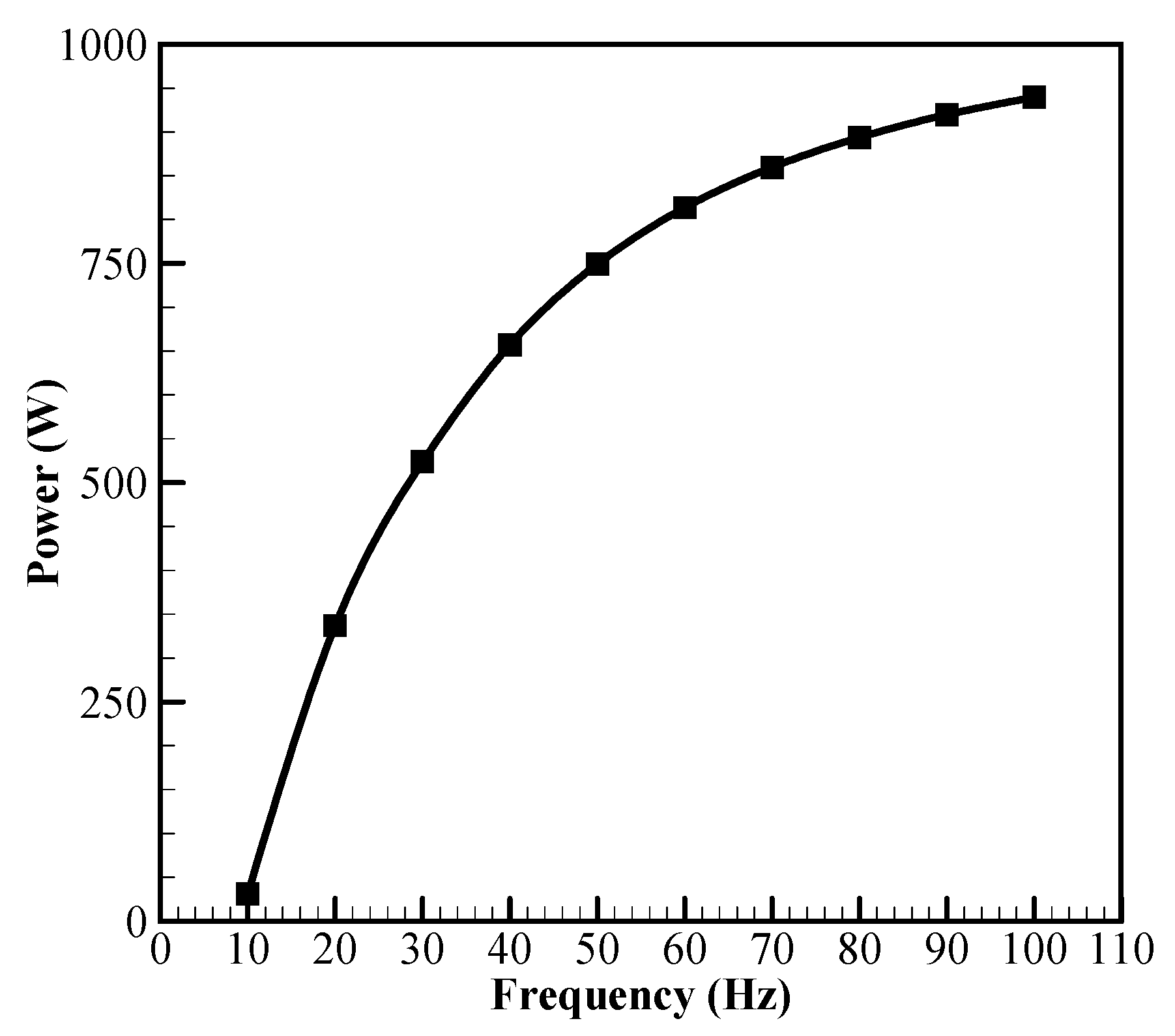
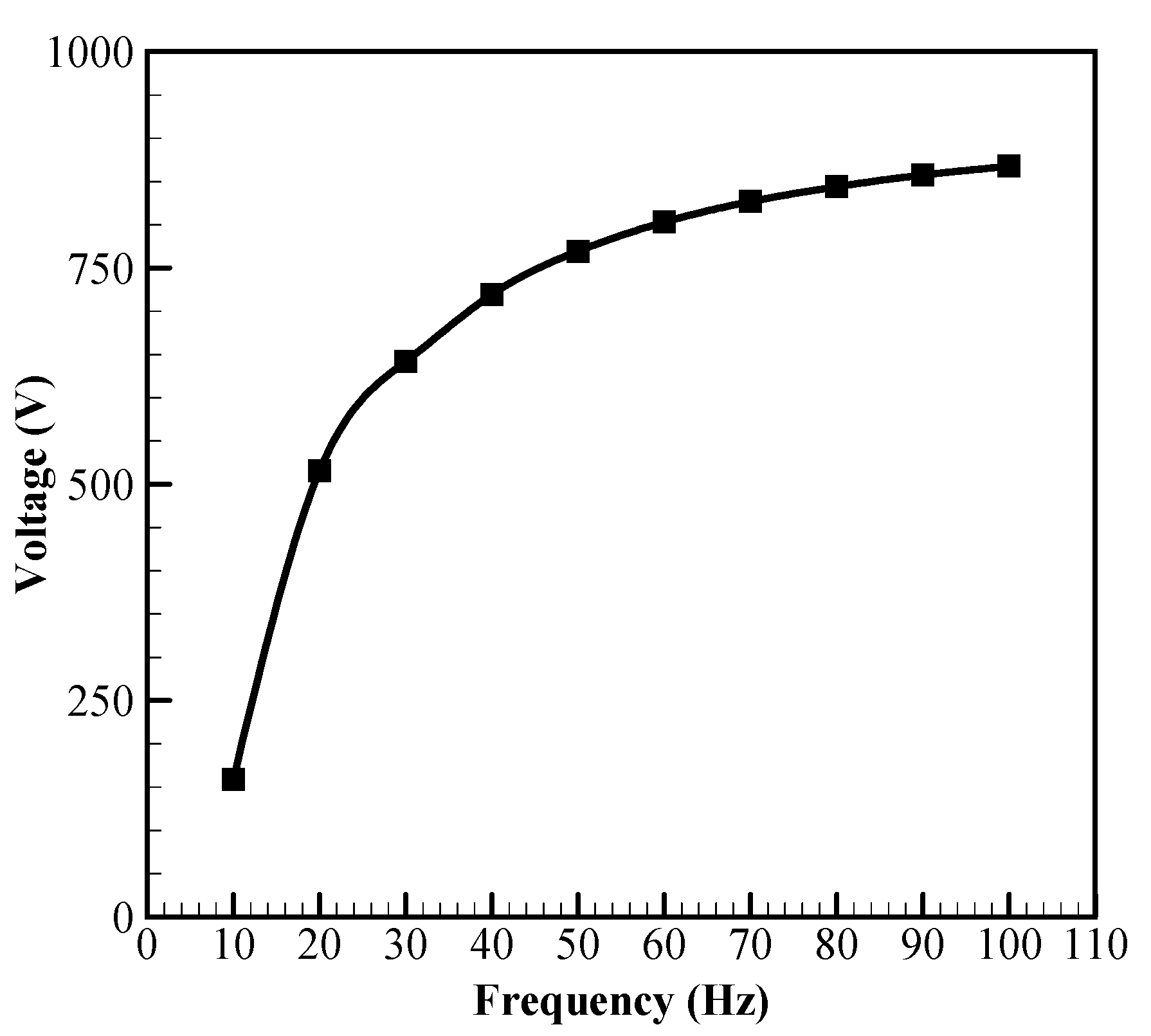
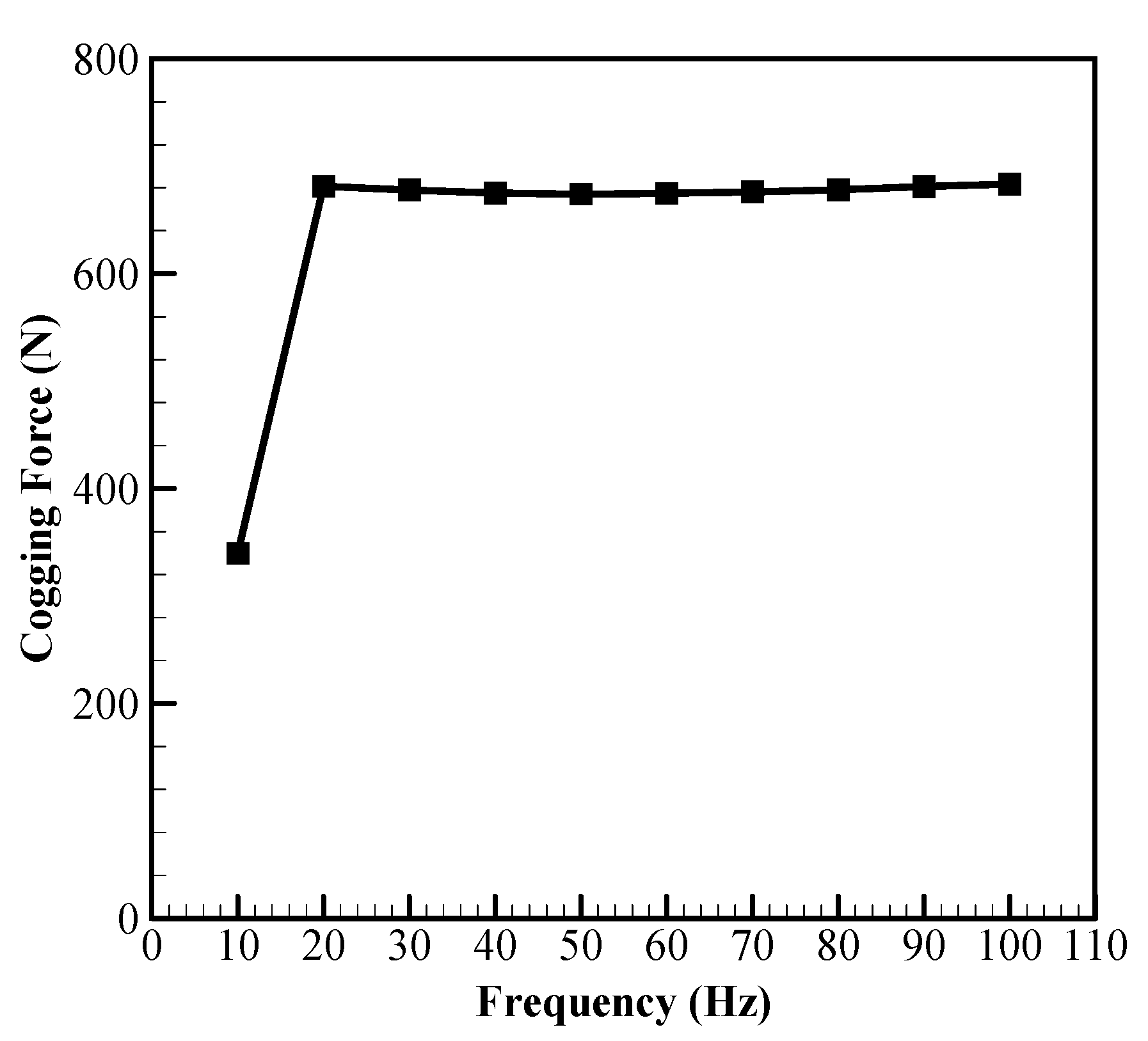
A level of saturation was seen after 60 Hz in the frequency variation. However, the domestic supply of Taiwan is fixed at 60 Hz, and hence was found to be a suitable solution that avoids post-processing of the induced EMF; most FPSEs operate within this range. The cogging force on the translator had a minuscule change due to the frequency variation and 939 W of power on the load in frequency variation.
(2)
With stroke length variation, there is a linear rise in induced voltage, varying beyond 40 mm, which is a design limitation, and applications with such inappropriate lengths are hard to find. A peak power of 7.1 kW was obtained for a 40 mm stroke, with the highest cogging force of 1.36 kN acting on the translator.
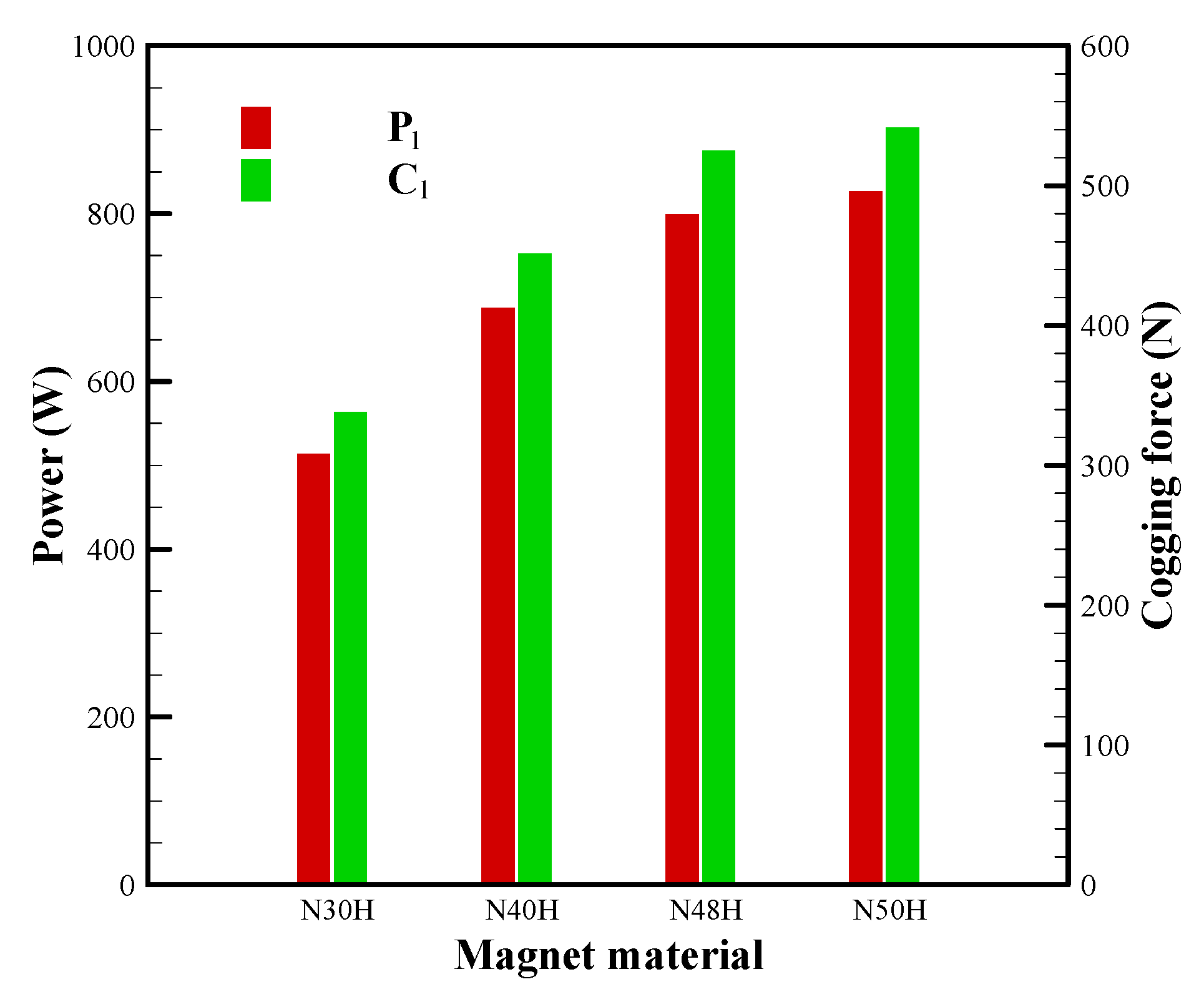
(3)
There was a linear rise in the induced power in the variation of magnetic material, and thus the cogging force. Hence, a balance between the required power delivery and an application to withstand the maximum cogging force felt on the translator should be chosen for specific applications.
(4)
The 35 series material has proven to be a better choice for the stator and shaft material, of which 35CS300 was found to have better-induced EMF than 35CS210. The iron loss in 35CS210 is comparatively lower, but the cogging force does not make a significant difference; hence, 35CS300 has proven to be a better material choice. Though having a considerable number of material choices for comparison, it was limited to a small number due to similar previous research [32].
(5)
Having values as low as 31 W and as high as 7116 W, the specific power varies from 1.4 W/kg to 313.5 W/kg. There is a wide band of power availability with this PMLA. Power-dense machines of such proportions have been possible in the past with suitable integrations.
(6)
Considering four parameters, a newer, lighter model from an existing conventional model has been developed which can provide more power under the same operating conditions. We came up with a PMLA that can produce a 7.1 kW peak power which is numerically analyzed and validated.

Author Contributions

Conceptualization, C.-H.C.; data curation, S.D.; formal analysis, C.-H.C.; funding acquisition, C.-H.C.; investigation, S.D.; resources, C.-H.C.; software, S.D.; supervision, C.-H.C.; writing—original draft, S.D.; writing—review and editing, C.-H.C. All authors have read and agreed to the published version of the manuscript.

Funding

This research received no external funding.

Institutional Review Board Statement

Not applicable.

Informed Consent Statement

Not applicable.

Data Availability Statement

Not applicable.

Conflicts of Interest

The authors declare no conflict of interest.

References

  1. Allen, M.; Antwi-Agyei, P.; Aragon-Durand, F.; Babiker, M.; Bertoldi, P.; Bind, M.; Brown, S.; Buckeridge, M.; Camilloni, I.; Cartwright, A.; et al. Technical Summary: Global Warming of 1.5 °C. An IPCC Special Report on the Impacts of Global Warming of 1.5 °C above Pre-Industrial Levels and Related Global Greenhouse Gas Emission Pathways, in the Context of Strengthening the Global Response to the Threat of Climate Change, Sustainable Development, and Efforts to Eradicate Poverty; IIASA: Laxenburg, Austria, 2019. [Google Scholar]
  2. Boldea, I.; Nasar, S.A. Linear Electric Actuators and Generators; Cambridge University Press (CUP): Cambridge, UK, 1999; pp. 3–43. [Google Scholar]
  3. Hung, N.B.; Lim, O. A review of free-piston linear engines. Appl. Energy 2016, 178, 78–97. [Google Scholar] [CrossRef]
  4. Gargov, N.P.; Zobaa, A.F.; Pisica, I. Investigation of multi-phase tubular permanent magnet linear generator for wave energy converters. Electr. Power Components Syst. 2014, 42, 124–131. [Google Scholar] [CrossRef] [Green Version]
  5. Rezaeealam, B. Permanent Magnet Tubular Generator with Quasi-Halbach Array for Free-Piston Generator System. Int. J. Power Electron. Drive Syst. (IJPEDS) 2017, 8, 1663–1672. [Google Scholar] [CrossRef] [Green Version]
  6. Loktionov, E.; Martirosyan, A.A.; Shcherbina, M.D. Solar Powered Free-Piston Stirling-Linear Alternator Module for the Lunar Base. In Proceedings of the 2016 2nd International Conference on Industrial Engineering, Applications and Manufacturing (ICIEAM), Piscataway, NJ, USA, 19–20 May 2016; pp. 1–6. [Google Scholar]
  7. Durcansky, P.; Nosek, R.; Jandačka, J. Use of Stirling Engine for Waste Heat Recovery. Energies 2020, 13, 4133. [Google Scholar] [CrossRef]
  8. Zhou, Y.; Sofianopoulos, A.; Lawler, B.; Mamalis, S. Advanced combustion free-piston engines: A comprehensive review. Int. J. Engine Res. 2018, 21, 1205–1230. [Google Scholar] [CrossRef] [Green Version]
  9. Wang, D.; Shuttleworth, R. Linear Alternator Design for Use in Heat Energy Recovery System. In Proceedings of the 6th IET International Conference on Power Electronics, Machines and Drives (PEMD 2012), London, UK, 27–29 March 2012; pp. 1–6. [Google Scholar]
  10. Dhar, M. Stirling Space Engine Program; National Aeronautics and Space Administration Glenn Research Center: Washington, DC, USA, 1999. [Google Scholar]
  11. Wood, J.G.; Buffalino, A.; Holliday, E.; Penswick, B.; Gedeon, D. Free-Piston Stirling Power Conversion Unit for Fission Surface Power, Phase I Final Report; NASA: Washington, DC, USA, 2010. [Google Scholar]
  12. Gecha, V.Y.; Goncharov, V.I.; Chirkin, V.G.; Shirinskii, S.V.; Petrichenko, D.A. Linear Alternator with Reciprocating Mover: Review of Designs and Machine Types. Biosci. Biotechnol. Res. Asia 2015, 12, 409–418. [Google Scholar] [CrossRef]
  13. Famouri, P.; Cawthorne, W.R.; Clark, N.; Nandkumar, S.; Atkinson, C.; Atkinson, R.; McDaniel, T.; Petreanu, S. Design and testing of a novel linear alternator and engine system for remote electrical power generation. In Proceedings of the IEEE Power Engineering Society. 1999 Winter Meeting (Cat. No. 99CH36233), New York, NY, USA, 31 January–4 February 1999; Volume 1, pp. 108–112. [Google Scholar]
  14. Cawthorne, W.; Famouri, P.; Chen, J.; Clark, N.; McDaniel, T.; Atkinson, R.; Nandkumar, S.; Atkinson, C.; Petreanu, S. Development of a linear alternator-engine for hybrid electric vehicle applications. IEEE Trans. Veh. Technol. 1999, 48, 1797–1802. [Google Scholar] [CrossRef]
  15. Ferrari, C.; Friedrich, H.E. Development of a free-piston linear generator for use in an extended-range electric vehicle. In Proceedings of the EVS26 International Battery, Hybrid and Fuel Cell Electric Vehicle Symposium, Los Angeles, CA, USA, 6–9 May 2012; pp. 1–6. [Google Scholar]
  16. Hodgins, N.; Keysan, O.; McDonald, A.; Mueller, M.A. Design and Testing of a Linear Generator for Wave-Energy Applications. IEEE Trans. Ind. Electron. 2011, 59, 2094–2103. [Google Scholar] [CrossRef]
  17. Brown, D.; Bao-Min, M.; Zhongmin, C. Developments in the processing and properties of NdFeb-type perma-nent magnets. J. Magn. Magn. Mater. 2002, 248, 432–440. [Google Scholar] [CrossRef]
  18. Ma, B.M.; Herchenroeder, J.W.; Smith, B.; Suda, M.; Brown, D.N.; Chen, Z. Recent development in bonded NdFeB magnets. J. Magn. Magn. Mater. 2002, 239, 418–423. [Google Scholar] [CrossRef]
  19. Eckert, P.R.; Igor, P.W.; Flores Filho, A.F. Design Aspects of Quasi-Halbach Arrays Applied to Linear Tubular Actuators. In Proceedings of the 10th International Symposium on Linear Drives for Industry Applications, Aachen, Germany, 27–29 July 2015; pp. 27–29. [Google Scholar]
  20. Lee, K.-S.; Lee, S.-H.; Park, J.-H.; Choi, J.-Y.; Sim, K.-H. Design and Experimental Analysis of a 3 kW Single-Phase Linear Permanent Magnet Generator for Stirling Engines. IEEE Trans. Magn. 2018, 54, 1–5. [Google Scholar] [CrossRef]
  21. Kumar, M.; Santosh, M.; Krishna, A.R.; Manisha, D. Permanent magnet linear generator design. IOSR J. Electr. Electron. Eng. 2015, 10, 86–90. [Google Scholar]
  22. Park, J.; Ko, J.; Kim, H.; Hong, Y.; Yeom, H.; Park, S.; In, S. The design and testing of a kW-class free-piston Stirling engine for microcombined heat and power applications. Appl. Therm. Eng. 2020, 164, 114504. [Google Scholar] [CrossRef]
  23. Sugiyantoro, B.; Rafsanjani, S.A.; Susilo, W.Y. Slotless Tubular Linear Permanent Magnet Generator Using Halbach-Array Excitation. In Proceedings of the 2018 10th International Conference on Information Technology and Electrical Engineering (ICITEE), Piscataway, NJ, USA, 24–26 July 2018; pp. 573–576. [Google Scholar]
  24. Li, Q.-F.; Xiao, J.; Huang, Z. Parametric study of a free piston linear alternator. Int. J. Automot. Technol. 2010, 11, 111–117. [Google Scholar] [CrossRef]
  25. Joubert, L.H.; Strauss, J.M. Optimisation of a Transverse Flux Linear Oscillating Generator by Transient 3D Finite Element Analysis. In Proceedings of the 2014 International Conference on Electrical Machines (ICEM), Piscataway, NJ, USA, 2–5 September 2014; pp. 602–608. [Google Scholar]
  26. de la Bat, B.; Dobson, R.; Harms, T.; Bell, A. Simulation, manufacture and experimental validation of a novel single-acting free-piston Stirling engine electric generator. Appl. Energy 2020, 263, 114585. [Google Scholar] [CrossRef]
  27. Lim, K.-C.; Woo, J.-K.; Kang, G.-H.; Hong, J.-P.; Kim, G.-T. Detent force minimization techniques in permanent magnet linear synchronous motors. IEEE Trans. Magn. 2002, 38, 1157–1160. [Google Scholar] [CrossRef]
  28. Eid, A.M.; Lee, H.W.; Nakaoka, M. Detent force reduction of a tubular linear generator using an axial stepped permanent magnet structure. J. Power Electron. 2006, 6, 290–297. [Google Scholar]
  29. Rezaeealam, B. Losses Computation in Reciprocating Tubular Permanent Magnet Generator with SMC Core. Int. J. Power Electron. Drive Syst. (IJPEDS) 2018, 9, 1545–1551. [Google Scholar] [CrossRef]
  30. Cawthorne, W.R. Optimization of a Brushless Permanent Magnet Linear Alternator for Use with A Linear Internal Combustion Engine. Ph.D. Thesis, West Virginia University, Morgantown, VA, USA, 1999. [Google Scholar]
  31. Mahmudzadeh, F.; Subramanian, J.; Famouri, P. Experimental Implementation of PLL for Free-Piston Engine Application. In Proceedings of the 2021 IEEE Texas Power and Energy Conference (TPEC), College Station, TX, USA, 2–5 February 2021. [Google Scholar]
  32. Yi-Jia, C. Integrated Model Analysis of a Free-Piston Stirling Engine Incorporated with a Linear Alternator. Master Thesis, National Cheng-Kung University, Tainan, Taiwan, January 2021. [Google Scholar]
  33. Schlune, H.; Plos, M.; Gylltoft, K. Safety formats for non-linear analysis of concrete structures. Mag. Concr. Res. 2012, 64, 563–574. [Google Scholar] [CrossRef]
  34. Castaldo, P.; Gino, D.; Mancini, G. Safety formats for non-linear finite element analysis of reinforced concrete structures: Dis-cussion, comparison and proposals. Eng. Struct. 2019, 193, 136–153. [Google Scholar] [CrossRef]
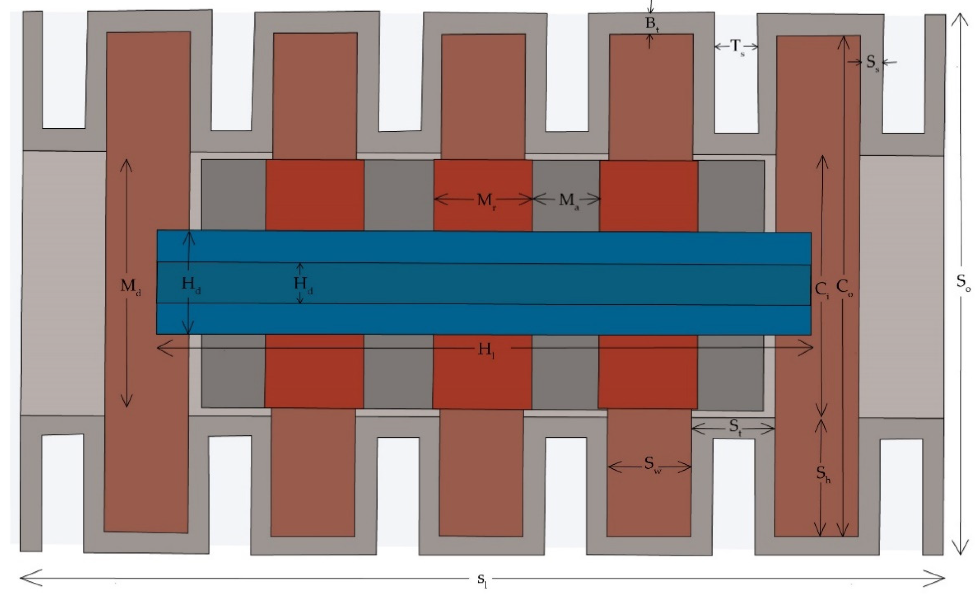
Figure 1. Slot spaced PMLA.
Sustainability 13 07192 g001
Figure 2. Magnetic flux density for a no-load baseline case: (a) Vector plot; (b) flux line at 10 mm from the stack.
Sustainability 13 07192 g002
Figure 3. Transient variation of no-load voltage and displacement.
Sustainability 13 07192 g003
Figure 4. Transient variation of cogging force and displacement.
Sustainability 13 07192 g004
Figure 5. Influence of frequency on power.
Sustainability 13 07192 g005
Figure 6. Influence of frequency on load voltage.
Sustainability 13 07192 g006
Figure 7. Influence of frequency on the cogging force.
Sustainability 13 07192 g007
Figure 8. Effect of stroke length on power.
Sustainability 13 07192 g008
Figure 9. Effect of stroke length on load voltage.
Sustainability 13 07192 g009
Figure 10. Effect of stroke length on the cogging force.
Sustainability 13 07192 g010
Figure 11. Effect of magnet material on power and cogging force.
Sustainability 13 07192 g011
Figure 12. Effect of magnet material on load voltage.
Sustainability 13 07192 g012
Figure 13. Effect of stator material on power and cogging force.
Sustainability 13 07192 g013
Figure 14. Effect of stator material on load voltage.
Sustainability 13 07192 g014
Figure 15. Comparison between the present and existing results.
Sustainability 13 07192 g015
Table 1. Geometrical parameters of PMLA.
ParametersDimensions (mm)
Stator Outer Diameter, So136
Slot Width, Sw21
Slot Height, Sh30
Back Iron Thickness, Bt5
Tooth Slot Thickness, Ss5
Tooth Slot Gap, Ts10.5
Stator Stack Length, Sl230.5
Magnet Outer Diameter, Md63
QH (Axial) Magnet Thickness, Ma16.5
QH (Radial) Magnet Thickness, Mr25
Coil Inner Diameter, Ci66
Coil Outer Diameter, Co125
Shaft Stack Length, Hl163.5
Shaft Inner Diameter, Hi16
Shaft Outer Diameter, Hd26
Air Gap1.5
Table 2. Mass of parts in PMLA.
PartMass (kg)
Stator7.6
Shaft4.1
Magnets2.7
Coils8.3
Table 3. Baseline case parameters.
Baseline ParametersParameter
Stator material35CS300
Magnet materialN48H
Stroke length (mm)10
Frequency (Hz)60
Table 4. Parameters and results comparison between reference [5] and present model.
Reference [5]Present Model
Back Iron Thickness (mm)14.70665
Tooth Slot Thickness (mm)-5
Tooth Slot Gap (mm)-10.5
Air Gap (mm)1.6511.5
Rms Force (N)24651416
Voltage (V)74128
Power (W)336618
Publisher’s Note: MDPI stays neutral with regard to jurisdictional claims in published maps and institutional affiliations.

