Abstract
Some valuable minerals, such as lignite, are extracted through open-pit mining works. After the cessation of mining activity, large-scale gaps result in the landscape. These gaps, also called “remaining gaps”, represent some of the roughest types of environmental impacts. After the cessation of mining activity, recovery and ecological restoration works are required. However, it is first necessary to carry out risk assessment studies considering the possible future influences on the final slopes. For this study, flooding of the remaining lignite open-pits gaps was considered as the ecological restoration option. The study was based on extensive research, including sampling, laboratory tests, statistical-mathematical processing, hypothesis formulation, evaluations, interpretations, and field observations, regarding the rock behavior and occurrence of negative geotechnical phenomena (geotechnical phenomena that have a negative impact and a risk on the integrity of the environment and local communities, such as landslides, rockfalls, liquefaction, suffosis) during the flooding process. This paper’s originality consists of combining the methods and methodologies developed with the help of classic methods (Fellenius, Janbu, and Bishop methods) and probabilistic ones (Rosenblueth method) existing in the specialized literature for solving the proposed problem and structuring the information similar to a guide.
1. Introduction
Worldwide, recovery and reuse of degraded lands has become a commonly used practice, with major and long-term benefits. As examples, countries such as Germany, Finland, the United Kingdom, the United States, and Canada can be listed [1,2]. Some of the reuse directions of the degraded mining lands are recreational areas, lakes with different functions, agricultural areas, museums, educational or scientific centers, tourist attractions, and controlled waste deposits [1,2].
In Romania, most of the mining-degraded lands are now occupied, for instance, by forests, crops, vineyards, and orchards, and the remaining gaps are used as settling ponds or as waste deposits. However, the problem is that there is no global concept of ecological restoration, which integrates into a whole unit an entire mining perimeter or even an entire mining basin.
As an ecological restoration method, flooding the remaining gaps of former open-pits is being applied increasingly frequently worldwide [3]. This method is economically acceptable, taking into account the long-term benefits such as reintegration into the landscape, ecosystem recovery, and land reuse. The opportunities are widely dependent on safety issues, including here the water quality and stability conditions of the final slopes [4].
The flooding process depends on the available volumes of water and the volume of the open-pit. Flooding can be achieved by two methods: naturally (water supply from precipitation, surface runoff, and aquifer formations) and artificially (water supply from natural sources through anthropogenic intervention, e.g., surface water additions, and the potential of artesian aquifer).
In this paper, we aimed to evaluate and analyze the failure/landslide risks in the conditions of flooding the remaining gaps of former lignite open-pits. The risk of failure has been evaluated in numerous works through different methods and methodologies. In most of the previous research, the failure risk was evaluated based on the critical failure surface with the minimum factor of safety combined with the limit equilibrum method (as is the case of the present paper) [5,6,7,8]. Some results have shown that the conventional analysis methods tend to underestimate the slope failure risk. However, for an initial determination of the critical failure surface, the conventional methods are considered.
The present paper is of great importance since slope stability is one of the most complex and challenging disciplines in the field of geotechnical engineering. It requires continuous development and improvements based on new research, data, experience, and practices.
In other research, a probabilistic approach has been made. The probabilistic analysis is useful when there is a complex stratigraphy and several critical failure surfaces. The probabilistic analysis allows for obtaining the most probable value of the stability limit, incorporating the influence of geotechnical uncertainty [8,9,10,11].
The assessment of slope stability is based on decades of research studies. Numerous researchers have brought together data, information, and facts, providing a set of principles and tools useful in the field of geotechnics. Starting from these, solutions can be found for stability problems. Additionally, new research in the field can serve as important sources for the development and improvement of the existing principles and analysis tools.
Studies conducted on failure risk of the final slopes of former open-pits in case of flooding are increasingly common [4,12,13,14]. Prospective analyses have the role of highlighting areas with failure potential. The success of these analyses and studies would mean reducing or even eliminating the risks of failure due to: (1) continuous improvement of working methods (sampling, processing, sample preservation, more measurements and tests); (2) the possibility of eliminating extreme values (the most unlikely values) considering the data are normally distributed (gaussian distribution); (3) smaller error (human or technical error), leading to better precision; and (4) obtaining reliable results.
The existing theory, resulting from long-term studies and which is based on the principles and tools mentioned above, is useful for performing prospective analyses which could be of major importance due to the possibilities of elimination of the failure risk. However, over time, retrospective analyses of landslides have provided the most information through systematic observation, sampling, field and laboratory testing, and analyses. Under the conditions of aquifer restoration and flooding the remaining gaps, the geotechnical characteristics of the rocks worsen due to the negative influence of water. Water is the main cause of negative geotechnical phenomena, such as landslides, and it has a negative influence mainly through the manifestation of pore water pressure and hydrodynamic pressure. Water also has positive effects on the stability in the conditions of submerged slopes. In this case, the water above the slope exerts a hydrostatic pressure behaving like a support prism [15].
The present study was conducted in the region of the North Pesteana open-pit. The results can be extended to the adjacent mining areas belonging to the Rovinari Mining Basin or other similar areas. The failure risk assessment methodology to be presented is a relatively simple and yet efficient tool being structured similar to a guide.
The proposed methodology was verified through eight slope stability examples (four dump slopes and four in-situ slopes), as can be seen in the following demonstrations. Although there are some limitations, the limit equilibrium method has a number of advantages and is easily applied, and the results obtained from the applications of this method have been accepted all over the world, often being used for guidance or as indicators of the stability reserve. The results obtained, in this paper, from the application of LEM-based methods were supported (or confirmed) by the behavior of slopes observed over several decades. There are also numerous stability studies (of which a number of 10 studies were cited in this paper), which confirms that the application of these methods is sufficient. It can be used as an indicator for the local authorities to assess the probability of occurrence of landslides and the vulnerability of objects in areas of influence (elements at risk).
In this paper, we aimed to encourage research in the geotechnical field, environmental engineering, and management of the remaining gaps of former lignite open-pits. Assessing the failure risk of slopes by applying simple but effective methods, such as the one described in this paper, allows a larger-scale assessment under acceptable economic and technical conditions. The safety of the anthropogenic and natural objects and the people in the influence areas of landslides represents the main goal of these types of studies or projects.
2. Materials and Methods
To identify the remaining gaps that are suitable for flooding in the context of ecological restoration of mining degraded lands, an opportunity assessment was made using the following evaluation criteria: geomorphology, orography, hydrology, hydrogeology of the region, the configuration of the remaining gap and final slope stability conditions, the necessity to restore the aquifer resources and to create body water in the area, accessibility and distance to the areas of interest, investments for the recovery and rehabilitation of the remaining gap, and population requirements. The opportunity assessment consisted of a qualitative assessment, the evaluation criteria being ranked with scores from 0 to 3, with 0 characterizing the inopportunity of flooding and 3 the major flooding opportunity of a remaining gap [16]. Therefore, the method of flooding former open-pits can be applied when there are favorable conditions which allow natural flooding in safe conditions with low investments, also satisfying the requirements of the local communities: development of the open-pit in the meadow areas, inflow of water from precipitation and aquifer formations, stable slopes before, during, and after the flooding process, the necessity of restoration of aquifer resources (restoration of water resources for local communities, maintenance of vegetation, crops, etc.), and compliance with the population requirement (taking into account that the pit lake can yield important functions with major ecological and economic benefits). Otherwise, it is recommended to choose another type of restoration.
The visual analysis of the deformations and changes occurring in a rock mass/rock deposit is an important step in the land stability assessment activity. To characterize the technical state of the slopes, several field observations were made in the North Pesteana mining perimeter since 2017. We identified fissures, cracks, erosion, suffosis zones, and superficial landslides (Figure 1). Still, these did not affect the overall stability of slopes, except for several larger landslides that occurred in early 2018 on the eastern slope of the quarry. These landslides affected the structure of the road that serves the mining perimeter [17,18]. Overall, these changes and modifications may endanger the stability of the individual/system of steps. Based on the visual analysis, deformations, changes, possible causes and other related effects were highlighted, identifying areas of potential risk.

Figure 1.
Deformations and changes observed during the visual analyses performed in the North Pesteana mining perimeter. (a) Pluvial erosion on the western slope of the open-pit; (b) Landslide affecting the technological road that serves the mining perimeter; (c) Cracks on the platform of the IInd dumping step; (d–e) The suffosis zones occurred on the IIIrd and IVth in-situ slopes [17,18].
Knowing the hydrological and hydrogeological characteristics of a region [15,19,20,21,22,23,24,25,26,27,28,29] allows us to evaluate the water availability and the possibility of flooding the remaining gap, but is also of particular importance in the context of geotechnical problems, as water has negative influences on the slope stability.
Geotechnical studies are not complete without determining, through the laboratory and/or in-situ tests, the geotechnical characteristics of the rocks. Therefore, we took disturbed samples from the North Peșteana mining perimeter (Figure 2) and performed laboratory tests (granulometric composition, moisture, volumetric and absolute specific weight defined by the ratio between the weight and volume including the pores of the rock, respectively the ratio between the weight and the volume of solid without pores, shear strength, and rock compressibility) to determine the geotechnical characteristics of the rocks (Figure 3) [18].
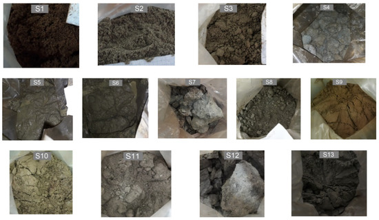
Figure 2.
Samples taken from the North Pesteana mining perimeter.

Figure 3.
Laboratory determination of geotechnical characteristics of the rocks. (a) Granulometric analysis; (b) Soil moisture; (c) Volumetric weight; (d) Shear strength; (e) Absolute specific weight; (f) Rock compressibility.
The latest data obtained from the laboratory tests (for the dump material) were used to complete the existing data sets that were taken from the studies carried out by specialists in the field over 4 decades. Subsequently, the data strings were subjected to statistical-mathematical processing.
It is difficult to obtain correct values of the physical and mechanical characteristics of rocks using disturbed samples, but we proceeded to load the material with a pressure equal to that existing in the field (taking into account the height of the rock column above the sample and its volumetric weight). Thus, we obtained a degree of compaction close to the one existing in the field. The results of tests are presented in Table 1. In addition, an important procedure that we applied, namely the statistical processing, ensured the obtaining of representative values of the geotechnical characteristics of the rocks. Statistical-mathematical data processing is a methodology that includes operations that ensure the transition from individual data to data and information that allows the characterization of the entire research community (in the case of the presented paper, this allowed the characterization of the geotechnical characteristics of rock). Processing involves synthesizing and comparing data so as to eliminate what is accidental and non-essential in the production and manifestation of the studied phenomenon. Any approach involving data processing involves several steps: data collection, centralization and grouping, data processing and calculation of the system of indicators that characterizes the researched community, and presentation of processing results in the form of series, tables, and/or graphs.

Table 1.
The physical and mechanical characteristics of rock from North Peșteana perimeter.
Based on the existing geotechnical boreholes and sections drawn in the areas of interest (Figure 4), the composition of the dumped material was determined depending on the nature of the rocks; it resulted that the waste rocks were mainly composed of a succession of clay (28.36%), marl (12.72%), sand (47.91%), gravel and boulders from the terrace (9.82%), and fertile soil (1.19%).

Figure 4.
Location of F1–F6 geotechnical boreholes and S1–S3 sections (section AA’).
The main geotechnical characteristics required in the stability studies are the volumetric weight, cohesion, and angle of internal friction. Based on the existing classifications in the specialty literature [15,18,19] and the ternary diagram [30], the classification and description of the analyzed samples were performed, resulting:
- S1—Sand (predominantly medium);
- S2—Sand (predominantly fine);
- S3—Silty-clayey sand;
- S4—Sandy clay;
- S5—Silty sand;
- S6—Sand with gravel elements;
- S7—Clayey silt;
- S8—Silt;
- S9—Sand (predominantly fine) with rare elements of gravel;
- S10—Sand with clay and gravel elements;
- S11—Sand with clay and gravel elements;
- S12—Coal rock in silty clay mass;
- S13—Sand (predominantly coarse) with gravel elements.
Rocks undergo significant changes in the sense of deterioration of their mechanical characteristics.
According to the specialized literature [15,19], the failure of the slopes is one of the main geotechnical risks that may occur in case of flooding the remaining gaps, along with the suffosis and liquefaction phenomena, erosion, abnormal settling, and others. The early assessment of geotechnical risks allows the establishment of risk reduction measures ensuring favorable conditions of stability and the security of the objects in the areas of influence.
2.1. Classic Methods of Slope Stability Analysis
Currently, slope stability is theoretically or practically estimated. The theoretical estimation is performed using different methods of calculation from the soil mechanics based on different types of rocks and calculation hypotheses. Practically, the slope stability is estimated by measuring the field deformations. The specialized literature mentions different calculation methods for analyzing the stablity of the slopes depending on the failure surface shape—plane [31], curved [32,33,34], or polygonal [35]. Given the fact that these methods are well known, we will not go into details.
In this study, stability analyses were performed using the Slide software [36] and methods based on curved failure surfaces: Fellenius, Janbu, and Bishop [32,33,34]. The Slide software allows for modelling slopes according to their geometry and defining the rock layers or mixture of rocks depending on their geotechnical characteristics. The software ensures the automatic calculation of the safety factor for all probable sliding surfaces and highlights the critical sliding surface.
The varying (heterogeneous) geological formations, the anisotropy of rocks, the sampling conditions, the working methods, and methodologies are some of the factors that may lead to a high dispersion of values for the geotechnical indices. Choosing representative values of the geotechnical characteristics is a difficult operation for which the statistical-mathematical processing of some comprehensive data strings is recommended [15].
The deterministic type of stability analysis presents errors such as inaccuracy, approximation, and simplifications induced by the terrain model and related to its non-homogeneity. In contrast, a probabilistic approach allows for examining errors with probability theory tools and addressing the source of uncertainty more rigorously and rationally.
2.2. Probabilistic Methods of Slope Stability Analysis
Probabilistic analysis replaces the notion of the safety factor to that of the stability limit. The stability limit is defined as the difference between the resistance forces and the failure forces (Equation (1)) [37,38].
where:
LS = Frez − Fal = Fs − 1,
- LS—stability limit;
- Frez—resistance forces;
- Fal—failure forces;
- Fs—safety factor.
The sources of uncertainty lead to the generation of a range of LS values possibly distributed according to a law of probability density (for example, Gaussian distribution). It is defined as the slide probability (Pr), the probability that the value of LS is less than 0 (LS = 0 represents the equilibrium condition).
Rosenblueth’s method [37,38], applied to verify the stability of a slope in soft rocks, allows for obtaining the average value of the stability limit and an indication of its dispersion (Equations (2)–(7)). These two values allowed for directly obtaining the value of the stability limit associated with a certain probability of failure (characteristic value of the stability limit) using Equation (8). The coefficient of variation of the stability limit is defined as the ratio between the standard deviation of the average stability limit and the average value of the stability limit (Equation (9)). The failure probability was obtained from the graph presented in Figure 5 by calculating the value of the parameter χ, which is associated with a value of LS = 0, provided by Equation (10).
where:
LS1 = Fsmin − 1,
LS2 = Fsmed − σ − 1,
LS3 = Fsmed + σ − 1,
LS4 = Fsmax − 1,
LSm = (LS1 + LS2 + LS3 + LS4)/4,
σLS = 0,5 ∙ √(LS12 + LS22 + LS32 + LS42),
LSk = LSm ∙ (1 + χ ∙ KLS),
KLS = σLS/LSm,
χ = −1/KLS,
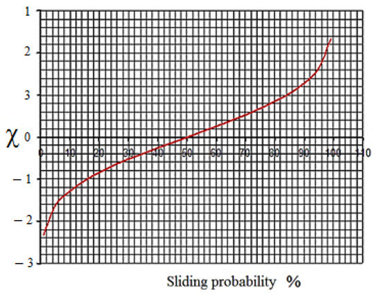
Figure 5.
Graphical representation of the failure probability according to the parameter χ (after [39]).
- Fsmin—minimum safety factor;
- Fsmed−σ—safety factor for average − σ values;
- Fsmed+σ—safety factor for average + σ values;
- σ—standard deviation of the geotechnical characteristics of the rocks;
- Fsmax—maximum safety factor;
- LSm—average value of the stability limit;
- σLS—standard deviation of the stability limit;
- LSk—characteristic value of the stability limit;
- KLS—variation coefficient of stability limit;
- χ—parameter depending on the probability distribution law.
The determined value of the failure probability must be related to the importance of the studied case and the degree of knowledge of the terrain’s characteristics [40].
2.3. Methods for Risk Assessment
Risk ranking is based on a matrix whose axes are represented by the severity of the consequences and probability. The combination between these two (usually the product between them), the severity of consequences and likelihood/probability, defines the risk. Numerous risk matrices have already been developed and implemented. A typical risk assessment matrix is the 3 × 3 matrix with three levels of risk according to the OHSAS standard/ISO45001:2018, recommended by the European Agency for Occupational Safety and Health. There are also matrices with more levels of probability, consequences, and risks [41]. Unlike other sources that use the 3 × 3 matrix or other simple matrices, we refined the risk evaluation process. Thus, we opted for a 5 × 5 matrix, represented by five classes of vulnerability and probability, based on which we separated six classes of risk. This model is acceptable when an extreme situation is defined, as can be seen in this paper.
The risks associated with geotechnical phenomena are the quantitative evaluation expressed in monetary units, the material or numerical losses, and the human casualties recorded as a result of the catastrophes caused by their occurrence.
From a qualitative point of view, the geotechnical risk was calculated as the product of the probability of manifestation of geotechnical phenomena and the vulnerability of the objects in the area according to the technical state of the slopes (Equation (11)).
where:
R = Pr ∙ V,
- R—the geotechnical risk;
- Pr—the probability of manifestation of geotechnical phenomena;
- V—the vulnerability of the objects in the area according to the technical state of the slopes.
Risk quantification can be based on a simple classification system wherein the probability and the vulnerability are ranked, assigning them representative scores. This allows for comparisons between different risks. The higher the result, the higher the priority for risk control.
2.4. A Simplified Failure Risk Assessment Methodology
Even though there are numerous methods and methodologies for risk assessment [12,13,41,42], improving or simplifying them or developing new ones represents a step forward in science and is a special challenge. The proposed methodology was based on four important steps and some essential sub-steps as shown in Figure 6.
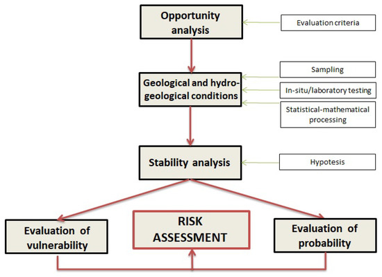
Figure 6.
Logical scheme of the proposed methodology for assessing the failure risks.
To be applied, the proposed methodology requires knowledge of several aspects.
The identification of the recovery, flooding, and reuse opportunity of the remaining gaps of former open-pits, by case, are made based on well-defined criteria. The higher the number of evaluation criteria, the more reliable the results [16].
The evaluation of the flooding opportunity allows for the identification of the open-pits that are suitable for flooding. Some of the most important evaluation criteria refer to the hydrological, hydrogeological, and geological conditions characteristic to the studied area, which allows for the evaluation of the stability conditions, character, and availability of water resources that can contribute to the flooding of the remaining gap, duration of the flooding process, etc.
Some of the abandoned remaining gaps of former open-pits are naturally flooded [3,14] and, in some cases, the newly created conditions have negative effects on the slope stability, leading to the manifestation of geotechnical phenomena such as landslides and liquefaction of dumped material. The identification of the danger (landslides, rockfalls, suffosis, or liquefaction phenomena, etc.) and the recognition of the most susceptible areas can be done, most easily, by in-situ investigations and visual analysis (observation of changes and deformations such as cracks, fissures, erosions, etc.).
Assessing the individual characteristics of the slopes (such as height, slope inclination, nature of the rocks, volumetric weight, cohesion, internal friction angle, etc.) was performed in-situ or in the laboratory. The working accuracy is affected by several factors (weather conditions and the depth of sampling influence their moisture, the precision of slope modelling), giving rise to errors. The errors, occurring since the sampling phase, could not be avoided or eliminated, but could be reduced, for example by repeated measurements/determinations. The data were subjected to statistical-mathematical analyses to obtain representative values that characterised the in-situ rock layers and the mixture of dumped rocks (data strings as long as possible are preferred).
An important step is the formulation of the hypotheses, based on which the stability analyses were performed. The hypotheses were formulated based on the experimental data, respectively on the values of the geotechnical characteristics considered representative and on the present (existing) and future (predicted) influences and conditions in the field.
Effective landslide risk assessment involves an estimation of the vulnerability of natural and anthropogenic objects in the area of influence and the probability of occurrence of such an event. Early risk assessment allows for the establishment and implementation of appropriate risk mitigation actions.
3. Results
The four steps of the proposed methodology were applied and verified for the particular case of the Rovinari Mining Basin (Figure 7).
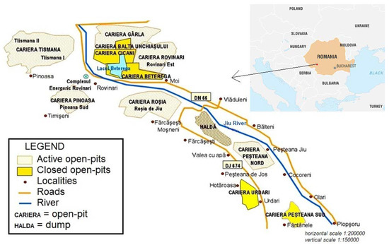
Figure 7.
Rovinari Mining Basin [20].
The Rovinari Mining Basin includes five active coal open-pits whose exploitation activity will cease in a maximum of 5 years, and this situation will require the application of solutions for the recovery of degraded lands. In the Rovinari Mining Basin, 12 open-pits have been put into operation over time, but only seven of them are still operational, these being grouped into five open-pit mining units: Rovinari, Tismana, Pinoasa, Rosia de Jiu, and North Pesteana. Some of the closed open-pits are used as a deposit for the slag and ashes from the Rovinari Power Plant, while others were recultivated or were abandoned and naturally reintegrated into the landscape (some as open-pit lakes: Urdari, South Peșteana).
3.1. Opportunity Analysis
As a result of the opportunity assessment [16], the remaining gap of the North Pesteana open-pit presents a major flooding opportunity. The major flooding opportunity results due to local conditions specific to the North Peșteana open-pit which favor this type of recovery. The lignite deposit is located entirely below the level of the surrounding land, so the probability of a resulting gap after the cessation of mining activity is high. The development of deposits in the meadow area of the Jiu River, respectively in a region with aquifer horizons of impressive dimensions (the Dacian aquifer complex) [20], has a positive influence in the conditions of restoring aquifer resources and flooding the remaining gap naturally, without major financial investments. Considering the agrarian specificity of the region, the major water requirements of the agricultural crops, and the drought periods, the creation of a lake has numerous benefits, constituting a source of water for crop irrigation. In addition, the lake could be used for recreational and leisure purposes or could have a naturalistic purpose [43]. The North Peșteana perimeter is located near the areas of interest (localities, agricultural lands), and access will become easy once the existing technological roads are asphalted. The demands of the population are one of the most important criteria on which the evaluation of the flooding opportunity was based. According to the results of an opinion poll [44], the population chose, in more than 75% of cases (Figure 8), the creation of a lake in the remaining gap of the Peşteana Nord open-pit.
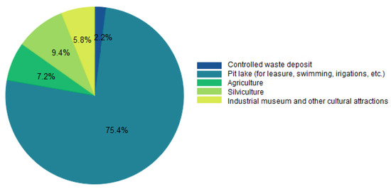
Figure 8.
Results of the opinion poll [44].
The configuration of the final slopes of the North Peșteana open-pit are presented in Figure 9, Figure 10 and Figure 11 and their geometrical characteristics are presented in Table 2.
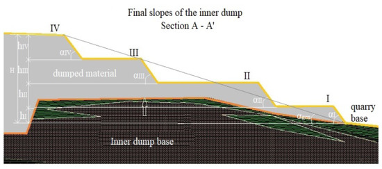
Figure 9.
The final slopes of the inner dump of the North Pesteana open-pit (location of section AA’ is shown in Figure 11).
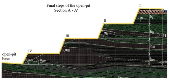
Figure 10.
The final in-situ slopes of the North Pesteana open-pit (location of section AA’ is shown in Figure 11).
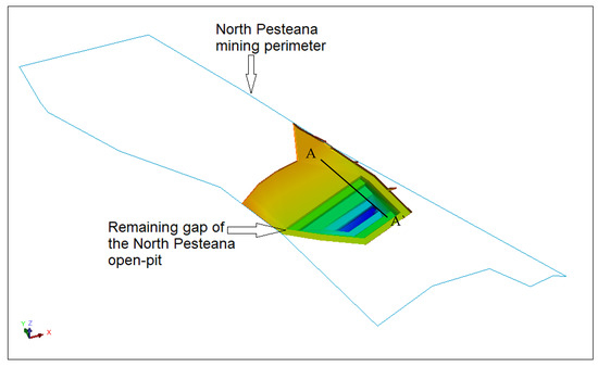
Figure 11.
3D shaping of the remaining gap [45].

Table 2.
The geometrical characteristics of the final slopes of the North Peșteana open-pit.
To evaluate the failure risks in the conditions of flooding the remaining gap of the North Pesteana open-pit, a series of research, studies, and preliminary analyses were necessary.
3.2. Geological and Hydrogeological Conditions
The lignite deposit in the Rovinari mining basin is located in Dacian, Romania, and Quaternary formations (belonging to both the Pleistocene and Holocene) are composed of 21 layers of lignite of which nine are exploitable (IV–XII), the upper layers (IX–XII) being eroded over large areas or even completely. The lignite layers are located between layers of sterile rocks that consist mainly of fine to coarse sands, clays, and marls.
According to analyses carried out on the hydrological (rainfall water has a relatively small but significant contribution to the flooding of the remaining gaps, of 10–20 mm/m2), hydrographical (Jiu River and its tributaries, some having a constant but small flow, while others have temporary flows which vary depending on the season and atmospheric precipitation), and hydrogeological conditions (phreatic layers, aquifer layers under pressure) specific to the region are favorable for flooding, but they also have a significant negative effect on the slope stability as a result of the worsening of geotechnical characteristics of the rock under the influence of the water (increasing of volumetric weight and decreasing of cohesion and internal friction angle) [45,46].
In-situ rocks are in a natural, undisturbed condition, while the waste rocks are in a loose state, their resistance structure being destroyed as a result of excavation, transport, and storage works. Therefore, from a stability point of view, more significant problems are raised by the dump slopes.
To determine the geotechnical characteristics of the rocks from the final slopes of the remaining gap of the North Pesteana open-pit, 13 disturbed samples were taken.
Table 3 lists the centralized the values of the geotechnical characteristics of the rocks (volumetric weight, cohesion, and internal friction angle), for both the natural and saturated rocks, to ensure quick analysis of the results.

Table 3.
The values of the geotechnical characteristics of the rocks in natural and saturated conditions.
Shear strength was determined by laboratory tests performed using a three-boxes (square boxes with side of 6 cm) direct-shear device. Three tests were performed for each rock sample, both at natural moisture (the one existing at the time of sampling) and at saturation. Normal pressures between 100 kN/m2 and 300 kN/m2 were applied. The shear test speed for all samples was 0.2 mm/min. Shear test results allowed for obtaining the shear strength parameter cohesion and internal friction angle, which are linked by the Mohr-Coulomb strength criterion [47].
Statistical-mathematical processing was carried out to obtain representative values of the geotechnical characteristics of the rocks (respectively for in-situ rock layers depending on the nature of the rocks and for the mixture of waste rocks). For this purpose, representative data (more than 100 data sets) from specialized literature [15,19], geotechnical studies elaborated by specialized institutions [20,21,22,23,24,25,26,27,28,29], and data obtained from laboratory determinations were taken into account.
In the case of in-situ rocks, the average values of the geotechnical characteristics were calculated, depending on the nature of the rocks (marls, clays, sands, boulders and gravels, lignite, vegetal soil), and in the case of a mixture of waste rocks, the weighted average values were calculated.
The results of the processing, for rocks in a natural state, are shown in Table 4.

Table 4.
The average values of the geotechnical characteristics of the rocks.
In the case of in-situ rocks, the stability analyses were performed based on the characteristic average values depending on the nature of the rocks.
3.3. Stability Analysis
Slope failure is one of the main problems that occurs in geotechnical engineering. Failure could cause the destruction of the environment, anthropogenic objects, and even the loss of human lives. Assessment of slope stability is an extremely important step. It requires rigorous analysis and consideration of all influence factors. Increasing rock moisture (as a result of the influx of water from precipitation or snow melting, surface water, or groundwater) has major negative effects on the stability of slopes, as it causes, on the one hand, the increase in volumetric weight of rocks, respectively the increase in failure forces and, on the other hand, the reduction of strength characteristics of rocks (cohesion and internal friction angle), respectively of the resistance forces. Therefore, the state of stress in the massif and in the dump changes considerably with the beginning of the flooding process of the remaining gap. Water in the lake has a positive effect on stability due to the hydrostatic pressure of the water, which opposes failure [15,19,48,49]. Depending on the physical and mechanical characteristics of the in-situ and waste rocks, it can reach the situation of raising the water level in the rocks (due to the capillary forces), the manifestation of the pore water pressure, and the hydrodynamic pressure which, again, negatively influences the stability.
Water causes a decrease in shear strength either by reducing the apparent cohesion or by creating or extending cracks, which represent potential slip surfaces when moisture increases [45,50].
The hydrological, hydrographic, and hydrogeological conditions specific to the region, the infiltration processes, and the porosity and permeability characteristics of the rocks are those that favor the penetration and circulation of water through rocks. The presence of water in rocks reduces the stability reserve by the negative effect of the water pressure in the pores which decreases the effective pressure on the sliding surface, which leads to the reduction of the shear strength and implicitly of the factor of safety [15,19,48,50,51,52,53].
The water pressure in the pores (Ui) negatively influences the stability of the slopes, as it determines the reduction of resistance forces, while in the case of submerged slopes the normal component of hydrostatic pressure (NiS) on the slope contributes to increased sliding resistance, as it increases the friction force. Therefore, even in this case, the pore water pressure is also manifested, but the depending on the water column and the pressure it exerts on the slope ensures a higher stability factor, resulting in the positive effect of water on slopes.
For the mixture of waste rocks, three hypotheses were established, and the stability analyses were performed based on three sets of values characteristic of these hypotheses: average values - σ, average values, and average values + σ, where σ represents the standard deviation (Table 5).

Table 5.
Sets of values subject to stability analysis.
Considering the three hypotheses, it was suggested that the set of average values provides the closest indications to the real situation, so these values are presented further.
As a result of the stability analyses, it was found that some areas were more prone to failure; therefore, to obtain more satisfying results, the stability and the risk of failure of the final slopes were evaluated in different stages of their flooding.
The evaluation of the stability of the slopes in different stages of the flooding of the remaining gap ensured a proper (and step by step) evaluation. For the case of the North Pesteana open-pit, eight flooding stages were considered (Figure 12), respectively:
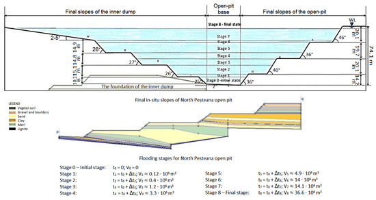
Figure 12.
Flooding stages. The scheme was made for the case of the remaining gap of the North Pesteana open-pit. Stages 0 and 8 represent the initial stage (the flooding has not started yet) and the final stage (all final slopes are submerged), respectively. Intermediate stages 1–7 correspond to the flooding of the final slopes (submerged conditions), one by one.
- Stage 0 (the initial stage), after the cessation of the exploitation activity, when the flooding had not started yet, and therefore under natural water drainage conditions (natural moisture of the rocks);
- Stages 1–7 (intermediate stages) when, one by one, the final slopes were submerged. Generally, the height of the pit steps varied (the in-situ steps, usually, were higher than the dump steps). Therefore, under these conditions, the total submersion of a slope (dump/open-pit) implies a partial submersion of the opposite slope (open-pit/dump);
- Stage 8 (the final stage), in which all the final steps of the remaining gap were submerged.
Stability analyses were performed using the Slide software (Rocscience, 2010) in different conditions (natural moisture, saturated rocks, and submerged slopes) and at different stages of flooding of the remaining gap (Table 6).

Table 6.
The values of the safety factors assigned to the eight flooding stages and the safety factors for the final individual steps in different conditions—Comparison of situations.
The three methods of stability analysis for curved sliding surfaces (Fellenius, Janbu, Bishop) provided close values of the safety factors, but only the minimum values (resulting from the application of Janbu’s method) were taken into account.
A slope is stable when the safety factor is higher than 1. In order to ensure the stability of the slopes in time, taking into account the influencing factors that may occur (water, vibrations, earthquakes, cracks, etc.), the stability reserve must be at least 25% for in-situ steps and 30% for dump steps. The stability assessment of the individual steps was carried out by the recommendations existing in the specialized literature, so the optimal value of the safety factor was in the range Fs = 1.25 ÷ 1.5 or higher for in-situ steps and Fs = 1.3 for dump steps (in Table 6, the lower values are highlighted) [15].
The results obtained from the data processing allowed for the analysis of the final slope stability, using Slide software, under three different conditions:
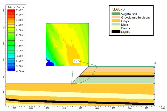 Figure 13. Stability analysis for the Ist in-situ step in conditions of natural moisture of the rocks.
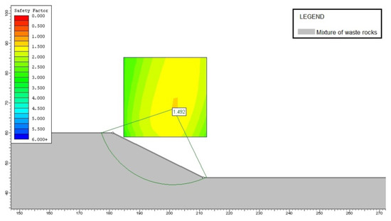 Figure 14. Stability analysis for the IVth dump step in conditions of natural moisture of the rocks.
Figure 13 shows the slope of the Ist in-situ step in conditions of natural moisture of the rocks. The result of the stability analysis indicated a safety factor for this slope of 1.235, which means the slope was stable. The stability reserve was still not enough, according to the recommendations, knowing that, during the restoration of aquifer resources and flooding of the remaining gap, the negative influence of water will manifest. It can be noticed that the phreatic aquifer is located in the gravels and boulders layer and, under the influence of water, may significantly reduce the stability reserve of the slope.
Figure 14 shows the slope of the IVth dump step in conditions of natural moisture of the rocks. The result of the stability analysis indicated a high safety factor of 1.492, which means there was an important stability reserve, first of all, due to the fact that there were no negative influences and also due to its favorable geometrical elements.
- saturated rocks—under the conditions of the aquifer resources restoration, respectively of the increase of the water level in the dump and of the manifestation of the water pressure in the pores (Figure 15 and Figure 16);
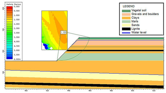 Figure 15. Stability analysis for the Ist in-situ step in conditions of saturated rocks and the manifestation of pore water pressure.
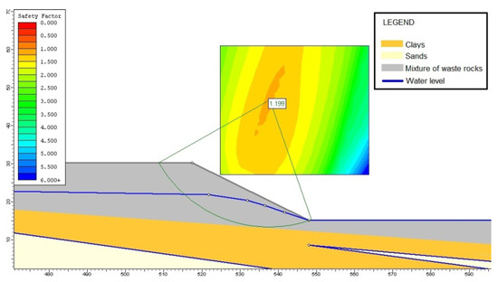 Figure 16. Stability analysis for the IInd dump step in conditions of saturated rocks and the manifestation of pore water pressure.
Slide software is a software capable of analyzing the stability even in the case of manifestation of pore water pressure in rocks or in case of submerged slopes and complies with the calculation algorithm existing in the literature. The piezometric line, in the case of the in-situ slopes, was defined up to the roof of the aquifer formation (except for the phreatic aquifer considering that the final level of the lake will coincide with it as the gravel allows water to drain) and the maximum hydraulic gradient determined for the North Pesteana mining perimeter (I = 0.03) was considered. The water level in the dump was defined depending on the water level in the lake and the maximum hydraulic gradient specific to the perimeter. The described situations were considered as being the worst situations.
Figure 15 shows the slope of the Ist in-situ step in conditions of saturated rocks and the manifestation of pore water pressure. As can be seen, a large decrease of the safety factors was registered (from 1.235 to 1.109), mainly as a result of large thickness aquifer layers, sands with very low values of cohesion, and internal friction angles in saturated conditions and the manifestation of pore water pressure.
In Figure 16, the slope of the IInd dump step in conditions of saturated rocks and the manifestation of pore water pressure is shown. The safety factor decreased from 1.538 (in natural conditions) to 1.199 as a result of the manifestation of pore water pressure and of capillary forces which determine the water level in the dump to rise before the level of the lake. According to the literature [15,19,48,52], if there is a clay fraction (which was found in the studied case: clay, marl, and various mixtures that include these fractions), it serves as the explanation for the reduction in stability. In order to ensure a high degree of safety for the objectives in the areas of influence, it was necessary to take into account an unfavorable hypothesis and define the water level in the dump higher than the water level in the lake respective of the maximum hydraulic gradient specific to the analyzed perimeter (I = 0.03).
- submerged slopes—under the conditions of aquifer resources restoration, respectively of the increase of the water level in the dump, of the manifestation of the water pressure in the pores, and the hydrostatic pressure on the slopes as a result of their submersion (Figure 17 and Figure 18).
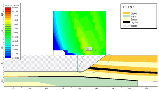 Figure 17. Stability analysis for the IInd in-situ step in the case of submerged slopes.
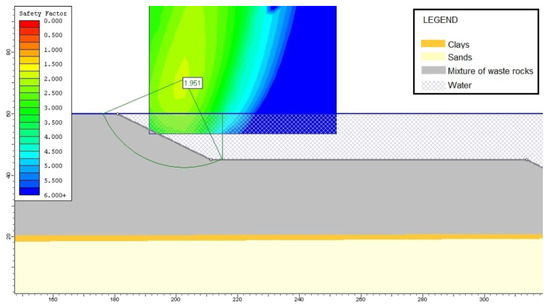 Figure 18. Stability analysis for the IVth dump step in the case of submerged slopes.
In Figure 17 and Figure 18, the submerged slopes of the IInd in-situ step and IVth dump step are shown. In both cases, an important increase of safety factor was observed due to the positive effect of the hydrostatic pressure manifested on the slopes. The water on the slope prevents it from sliding. In sands, we can consider the reduction of water in the pores as a result of the drainage of water through the slopes, which determines the reduction of the hydrostatic level, respectively of the pressure. The pore water pressure cannot be manifested as long as the slopes are not covered by water as a result of the drainage process. The Slide software also calculated the distribution of pore water pressure corresponding to the analyzed section, distribution shown in Figure 19 and Figure 20, and it was observed that the pore water pressure decreased towards the base of the slope as a result of the pressure exerted by the column of water on the slope.
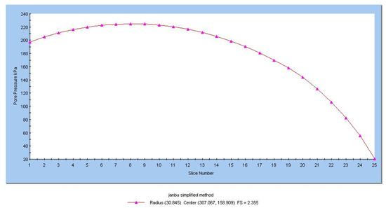
Figure 19.
Distribution of pore water pressure for the case of the IInd in-situ step (submerged slopes). The Slide software numbers the strips from left to right.
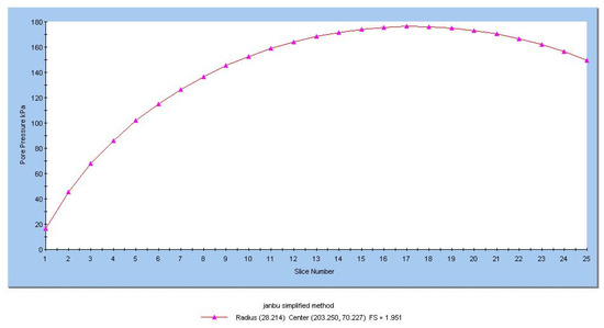
Figure 20.
Distribution of pore water pressure for the case of the IVth dump step (submerged slopes). The Slide software numbers the strips from left to right.
For natural moisture conditions, there is an acceptable stability reserve for all final slopes.
As can be seen, the minimum safety factor resulted in the case of partially submerged slopes. These are the minimum values possible, as the most unfavorable conditions (saturated rocks and the manifestation of pore water pressure) were taken into account.
We found large decreases of the safety factors (in comparison with the natural moisture conditions) at the IIIrd and IVth in-situ slopes, of 37% and 42%, which are explained by the existence of large thickness aquifers layers and sands where the values of the resistance characteristics are small in saturated conditions. In the case of submerged slopes, the safety factor (Fs higher than 1) indicated a significant stability reserve; therefore, all the final slopes were stable.
Moreover, there were increases of up to 43% in the safety factors in the case of the in-situ steps and up to 35% in the case of the inner dump steps, compared with the natural moisture conditions.
Therefore, to reduce the risk of failure, it is recommended to accelerate the flooding process, as the water manifests a hydrostatic pressure favorable for the stability reserve.
3.4. Failure Risk Assessments of Final Slopes
Landslides (including both natural landslides/natural slope failure and mining-induced failure/artificial slope failure) are one of the main geotechnical risks. The risk associated with slope failure is defined as the product between the failure probability and the vulnerability of the objects in the area according to the technical state of the slopes. Therefore, risk can be assessed only after collecting all the necessary input data.
The values of safety factors were used to estimate the probability of failure using Rosenblueth’s method, but also to estimate the vulnerability of the objects using the classification of rock massifs/deposits by hazard groups taking into account the technical state of the in-situ and dump slopes.
At the time of cessation of mining activity in the open-pit, the situation of the remaining gap must be certain. Therefore, the future destination must be known, the stability conditions of the final slopes must be evaluated taking into account the influence of external or internal factors, and coverage coefficients of stability are ensured. In the North Pesteana mining perimeter, there were superficial landslides, some of them affecting the structure of the technological road. These did not endanger the overall stability of the steps.
The classification by hazard groups of the rock massifs/deposits according to the nature of the objects in the area of influence and the degree of stability, existing in the specialized literature, was completed with the natural objects and five categories of vulnerability of the objects were established depending on the technical state of the final slopes (Table 7) [18,54,55,56].

Table 7.
Classification of rock massifs/deposits according to the nature of the objects in the area and establishment of the vulnerability of the objects [18,54,55,56].
The columns 1, 2, 3, and 4 represent hazard groups and lines 1, 2, 3, and 4 represent the value of the objects. The existence of a relationship between the hazard groups and the value of the objects was highlighted by marking the cells at the intersection of the lines with the columns, like a matrix. This intersection can be marked in various other ways.
To define the vulnerability of the objects depending on the technical state of the final slopes the following categories of vulnerability were established:
- V = 1—very low vulnerability;
- V = 2—reduced vulnerability;
- V = 3—medium vulnerability;
- V = 4—high vulnerability;
- V = 5—very high vulnerability.
In the area of the final in-situ slopes, taking into account the technical state of the slopes (displacements that can be limited by arrangements or by exploitation technology; overall, these slopes were included in class 3) and the objects in the area of influence (agricultural lands, pastures, forests, Jiu river and other streams, domestic or wild animals, villages, individual households, DN66 national road, DJ674 county road, utility, and telecommunication networks; overall, these objects were included in class 1), we considered that the objects presented high vulnerability (V = 4).
In the area of the final dump slopes, based on the same considerations, we considered that the objects presented medium vulnerability (V = 3) as the objects in the area of influence consisted of industrial constructions and equipment (overall, these objects were included in class 2).
Therefore, we can consider an average value of 3.5 for the vulnerability class that characterized the studied objective (the North Pesteana open-pit) as a whole. For this assessment, we considered that the areas of influence of the final slopes of the open-pit were equally sensitive.
By applying Rosenblueth’s method and using the minimum values of safety factors obtained from the stability analysis, the necessary elements to evaluate the failure probability of the slopes were determined (Table 8) and, based on the graph in Figure 2 and on the value of χ, the failure probability of the slopes for rocks in the natural and saturated state was established.

Table 8.
Determination of failure probability and risk.
Based on the existing models in the literature [38,56,57], the following scale was established to define the probability of failure (Prf):
- Pr = 1 for Prf < 15 % → very low probability of failure;
- Pr = 2 for 15 % ≤ Prf < 35 % → low probability of failure;
- Pr = 3 for 35 % ≤ Prf < 65 % → medium probability of failure;
- Pr = 4 for 65 % ≤ Prf < 85 % → high probability of failure;
- Pr = 5 for Prf ≥ 85 % → very high probability of failure.
Using the scale for defining the probability of failure of each step, the corresponding score was found and the risk of failure of the slopes was determined (based on Equation (11)), both for natural rocks and for saturated rocks.
The results indicated a higher probability of failure in the case of in-situ slopes (of 23–37%) than in the case of dump slopes (18–22%). In a saturated state, in all cases, there was a significant increase in the probability of failure than in the natural state that varied between 31–67% for in-situ steps and between 23–35% for dump steps. Overall, the probability of failure was low to medium, except for the IIIrd in-situ step which, in a saturated state, had the highest probability of failure, most likely because of the large thickness of the sandy layer which presented low-resistance characteristics.
Considering the five vulnerability classes and five probability classes, a risk evaluation matrix was suggested (Table 9).

Table 9.
Risk evaluation matrix.
Based on the risk evaluation matrix, the following scale was established to assess the failure risk:
- For R = 1 → very low risk of failure;
- For 1 < R ≤ 4 → low risk of failure;
- For 4 < R ≤ 9 → medium risk of failure;
- For 9 < R ≤ 15 → high risk of failure;
- For 15 < R < 25 → very high risk of failure;
- For R = 25 → extremely high risk of failure.
In this case, the in-situ slopes were more prone to failure compared with the slopes of the dump. The high risk of failure estimated for the in-situ steps (Ist, IIIrd and IVth steps) can be explained by the presence of aquifer layers (gravel and sand) with large thicknesses, while for the steps of the dump there was a real risk of failure with the flooding of the lower steps as the water level in the dump increased gradually before being equaled by the water level in the lake. Thus, the resistance characteristics worsened, as can be seen for the case of the IVth dump step, whose geometry was not favorable under these conditions. Overall, the final risk resulted from the most unfavorable situations. Thus, the results indicated a high risk of failure of the final slopes of the North Pesteana open-pit.
4. Discussion
Based on the results obtained and on the main three conditions considered (natural moisture, saturated rocks, submerged slopes) in the stability analysis and the different stages of flooding, more discussions are required.
The proposed methodology was verified in the case of North Peșteana open-pit. From case to case, the flooding duration depends on the volume corresponding to each stage of flooding and on the volume of water that contributes to the flooding of the remaining gap.
The failure risk assessment is necessary before the slopes encounter external influences that reduce the stability reserve. The initial stage is common to all cases and involves the assessment of stability in conditions of natural water drainage. In the final stage, in the conditions of submerged slopes, they usually have a high stability reserve due to the hydrostatic pressure manifested on the slope and due to the geometric elements of the slopes, designed to provide a high degree of safety. Instead, the intermediate stages differ from case to case, and they can be customized (as the number, as water level, as flood duration, etc.) These steps are essential, and the proper establishment of these steps ensures a proper assessment.
The evolution of the safety factor of the final slopes depends directly on the duration of the flooding process [49]. The flood duration depends on the volume of the remaining gap and the available water flow from natural or artificial sources, being defined by the ratio between the two elements: the volume, V, and, respectively, the flow, Q.
Based on the values presented in Table 6, before and after the complete flooding of the remaining gap, there was an acceptable stability reserve, both for the in-situ and dump slopes. The most important variations occurred in the intermediate stages, especially in the case of the partially submerged slope. Additionally, as the water level on a slope increased, the stability reserve increased. This is why, after the complete flooding of one step, the safety factor for that slope was no longer of interest, as it could not decrease (the flooding, in the case of North Peșteana gap, is caused mostly by deep aquifer resources, which are not influenced by normal climatic and meteorological fluctuations, including excessive rainfall or droughts such as those recorded so far). Therefore, each time, we analyzed the upper slope to be flooded.
As can be seen, the safety factor was higher when a slope was completely submerged than in the case of the same slope, but partially submerged; this was a result of the manifestation of hydrostatic pressure on the surface of the slope, which acts as a support prism. Analyzing carefully, it can be observed that every time the water level rose on the surface of a slope, the safety factor encountered a significant decrease, followed by a significant increase—the same results were recently observed, according to [49].
The minimum values were also represented and it can be seen that the risk of failure occurred, generally, in the case of the partially submerged slope as a result of the restoration of aquifer resources, of the increase of hydrostatic level in the massif/dump due to the action of capillary forces, and of the manifestation of pore water pressure.
Even if the assessment was made for the case of the North Pesteana open-pit, the situation of other remaining gaps is similar to this one. From case to case, the nature of in-situ and waste rocks, the configuration of the remaining gaps, and the sources and quantity of water available for flooding differ. The failure risk tends to be higher in the case of partially submerged slopes and lower in the case of submerged slopes. Therefore, as the flooding duration is an important key in the flooding process and in reducing the failure risk, it is recommended to find the optimal flooding solutions.
In the case that a significant risk is estimated, to reduce it, to control and prevent the hazard, it is recommended to apply the appropriate solutions and measures. Some of the solutions and measures that are efficient from the technical and economical point of view are: redesigning the geometric elements of the slope (reshaping, removing material from the area driving the landslide, adding material to the area maintaining stability, leveling, compacting, vegetation), water drainage works (surface drains, trench drains, dewatering boreholes with pumping or self-draining, drainage tunnels, galleries, etc.), retaining structures (retaining walls, passive piles, reinforced earth retaining structures, retention nets for rock slope faces, rock trap ditches, benches, fences, etc.), and internal slope reinforcement (rock bolts, micro piles, soil nailing, anchors, grouting, stone or lime/cement columns, cementing non-cohesive rocks, etc.) [58].
In addition to the slope stabilization works, for the faster raising of the water level in the remaining gap, works to accelerate the flooding process are required. Acceleration of the flooding process can be performed by water adductions from water bodies or watercourses located nearby.
To reduce the risk of occurrence of other geotechnical phenomena, such as suffosis and liquefaction phenomena, the acceleration of the flooding process can be performed concomitantly with dewatering works to control the water inflow from the aquifer formations (to reduce the hydrodynamic pressure and the risk of suffosis; hydrodynamic suffosis occurs when the filtration speed of groundwater exceeds the critical speed and the fine particles of sandy rocks are driven by water under the action of hydrodynamic pressure) and to control the water level, especially in the inner dump (in order to reduce the manifestation of the pore water pressure and the liquefaction of loose sandy rocks).
5. Conclusions
Flooding the remaining gaps of former open-pits is an efficient method to recover degraded mining lands. This method is increasingly frequently used worldwide. It has several benefits, both from an ecological and economical point of view, such as restoration of aquifer resources and local ecosystems, occurrence of a new ecosystem (an aquatic one), new possibilities of land reuse (recreational and leisure activities, swimming and other water sports, fishing, fish farming for economic development of the region), possibilities of using it as a retention basin for protection against the floods, use of lake water for irrigation during longer periods of drought, etc.
The study aimed to present a methodology for assessing the failure risks that may occur in flooding the remaining gaps of former open-pits. The logical scheme, which describes the four steps of the methodology, is a simple one and allows for the imposition of new conditions, to ensure proper evaluation, from one case to another.
This methodology was applied and verified for the case of the remaining gap of the North Pesteana open-pit, which will cease its activity in the following years (maximum 7 years), being necessary to establish the conditions of recovery, ecological restoration, and reuse. Following the evaluation of the flooding opportunity, it was found that it presented favorable natural flooding conditions. Stability analyses and risk assessment were performed for different situations, taking into account both present conditions (natural drainage of aquifers) and future conditions (restoration of aquifer resources, the manifestation of water pressure in the pores, rising water levels in the lake, and manifestation of hydrostatic pressure on the final slopes of the open-pit). In this case, the in-situ slopes were more prone to failure than the dump’s slopes. This situation can be explained by the presence of in-situ aquifer layers (gravel and sand) with large thicknesses. In the case of the inner dump, a real risk of failure was found for the upper step. Its geometry is not favorable under the conditions of flooding of the lower steps as the water level in the dump increases, determining the worsening of geotechnical characteristics of the dumped rocks.
As a result of the assessment of the failure risk, it was confirmed that it increased with the increase of the water level in the rocks and the dump (as a result of capillary forces); it was also found that partially submerged slopes were the most prone to failure. Additionally, the risk of failure was higher in the last stages (just for the partially submerged slopes), where the volume to be flooded is higher as the water level in the lake rises more slowly. Therefore, the water in the rocks (in the capillary and subcapillary pores) tends to rise, thus exceeding the water level in the lake, a situation that involves the worsening of the geotechnical characteristics of the rocks and the reduction of the stability reserve.
The flooding process of the remaining gaps has important advantages in the final stage due to the hydrostatic pressure acting on the surface of final slopes, like a support prism, increasing their stability reserve. In the initial stage, when natural moisture is considered, the risk of failure varies from one case to another, as the site’s characteristics (nature of rocks, geotechnical characteristics of the rock, geometrical elements of the slopes, etc.) also vary. When failure risk exists from the initial stage, several measures and solutions must be established and implemented before the flooding process begins.
As a result (possibly generally valid) of this study, we can state that the risk of failure is higher during the intermediate stages when the slopes are partially submerged.
The importance of the proposed methodology consists of knowing the risks of failure of the final slopes of an open-pit before starting the ecological restoration of the land, the main goal being the increase of the safety degree for humans and objects in areas of influence.
Author Contributions
Conceptualization, I.-M.A., M.L. and F.F.; data curation, I.-M.A., M.L. and F.F.; formal analysis, M.L. and F.F.; funding acquisition, M.L.; investigation, I.-M.A. and F.F.; methodology, I.-M.A., M.L. and F.F.; project administration, I.-M.A., M.L. and F.F.; resources, I.-M.A., M.L. and F.F.; software, I.-M.A., M.L., and F.F.; supervision, M.L.; validation, M.L. and F.F.; visualization, I.-M.A. and M.L.; writing—original draft, I.-M.A.; writing—review & editing, I.-M.A., M.L. and F.F. All authors have read and agreed to the published version of the manuscript.
Funding
The APC was funded by the RAFF project (Risk Assessment of Final Pits During Flooding) co-financed by the Research Fund for Coal and Steel (RFCS) under the Grant Agreement No-847299-RAFF.
Institutional Review Board Statement
Not applicable.
Informed Consent Statement
Not applicable.
Conflicts of Interest
The authors declare no conflict of interest. The funders had no role in the design of the study; in the collection, analyses, or interpretation of data; in the writing of the manuscript, or in the decision to publish the results.
References
- Wirth, P.; Černič, B.M.; Fischer, W.; Harfst, J.; Horváth, G.; Csüllög, G.; Lipovská, Z.; Vaishar, A.; Šťastná, M.; Osebik, D.; et al. Post-Mining Regions in Central Europe—Problems, Potentials, Possibilities; Oekom: München, Germany, 2012. [Google Scholar]
- Kivinen, S. Sustainable Post-Mining Land Use: Are Closed Metal Mines Abandoned or Re-Used Space? Sustainability 2017, 9, 1705. [Google Scholar] [CrossRef]
- Gammons, C.H.; Harris, L.N.; Castro, J.M.; Cott, P.A.; Hanna, B.W. Creating lakes from open pit mines: Processes and considerations, with emphasis on northern environments. Can. Tech. Rep. Fish. Aquat. Sci. 2007, 2826, 106. [Google Scholar]
- McCullough, C.D.; Schultze, M.; Vandenberg, J. Realizing beneficial end uses from abandoned pit lakes. Minerals 2020, 10, 133. [Google Scholar] [CrossRef]
- Chu, X.; Li, L.; Cheng, Y. Risk assessment of slope failure using assumption of maximum area of sliding mass and factor of safety equal to unit. Adv. Civil Eng. 2019, 2019, 11. [Google Scholar] [CrossRef]
- Chu, X.; Li, L.; Wang, Y. Slope reliability analysis using length-based representative slip surfaces. Arab. J. Geosc. 2015, 8, 9065–9078. [Google Scholar] [CrossRef]
- Zhang, J.; Zhang, L.M.; Tang, W.H. New methods for system reliability analysis of soil slopes. Can. Geotech. J. 2011, 48, 1138–1148. [Google Scholar] [CrossRef]
- Duncan, J.M.; Wright, S.G.; Brandon, T.L. Soil Strenght and Slope Stability, 2nd ed.; John Wiley & Sons: Hoboken, NJ, USA, 2014. [Google Scholar]
- Reale, C.; Xue, J.; Pan, Z.; Gavin, K. Deterministic and probabilistic multi-modal analysis of slope stability. Comp. Geotech. 2015, 66, 172–179. [Google Scholar] [CrossRef]
- Chakraborty, R.; Dey, A. Effect of spatial variation of soil on probabilistic slope stability analysis for cut slopes. In Proceedings of the International Conference on Landslides and Slope Stability (Slope 2019), Bali, Indonesia, 25–27 September 2019; p. C1-1-8. [Google Scholar]
- Griffiths, D.V.; Zhu, D.; Huang, J.; Fenton, G.A. Observations on Probabilistic Slope Stability Analysis. In Proceedings of the 6th Asian-Pacific Symposium on Structural Reliability and Its Applications, Shanghai, China, 28–30 May 2016. [Google Scholar]
- Graaf, P.; Desjardins, M.; Tsheko, P. Geotechnical risk management for open pit mine closure: A sub-arctic and semi-arid case study. In Proceedings of the Proceedings of the 13th International Conference on Mine Closure, Pert, Australia, 3–5 September 2019. [Google Scholar]
- Sandercock, P.; Ladson, T. Risk assessment of floodplain mining pits in the mid-Goulburn Valley, Project no: IS089100; Jacobs and Moroka: Goulburn Broken, Australia, 2015. [Google Scholar]
- Schultze, M.; Pokrandt, K.H.; Hille, W. Pit lakes of the Central German lignite mining district: Creation, morphometry and water quality aspects. Limnologica 2010, 40, 148–155. [Google Scholar] [CrossRef]
- Rotunjanu, I. Slopes Stability; Infomin: Deva, Romania, 2005. (In Romanian) [Google Scholar]
- Apostu, I.-M.; Lazar, M.; Faur, F. A Model to Evaluate the Flooding Opportunity and Sustainable Use of Former Open-Pits. Sustainability 2020, 12, 9275. [Google Scholar] [CrossRef]
- Apostu, I.M.; Lazar, M.; Faur, F. Visual Analysis of Deformations from the Quarry and Inner Dump Steps from North Pesteana Mining Perimeter; Annals of the University of Petrosani, Mining Engineering Universitas: Petroşani, Romania, 2018; Volume 19, pp. 115–121. [Google Scholar]
- Nyari Apostu, I.M. Researches Regarding the Geotechnical risks in Conditions of Flooding of Former Lignite. Ph.D. Thesis, University of Petrosani, Petrosani, Romania, 2019. (In Romanian). [Google Scholar]
- Stănciucu, M. Slopes Stability; Technical University: Cluj-Napoca, Romania, 2018. (In Romanian) [Google Scholar]
- Institute for Scientific Research, Technological Engineering and Lignite Mine Designs—S.A. Craiova (I.C.S.I.T.P.M.L.). Report on the Environmental Impact Study, Continuation of Mining Works in the North Pesteana Perimeter Proposed to Be Located in the Extravilan/Intravilan Areas of Urdari, Bălteni and Plopșoru Communes, Gorj County, Symbol 810—537; I.C.S.I.T.P.M.L.: Craiova, Romania, 2012. [Google Scholar]
- Institute for Scientific Research, Technological Engineering and Lignite Mine Designs—S.A. Craiova (I.C.S.I.T.P.M.L.). Geotechnical Study—North Peșteana Open-Pit, sb. 810-510; I.C.S.I.T.P.M.L.: Craiova, Romania, 2007. (In Romanian) [Google Scholar]
- Institute for Scientific Research, Technological Engineering and Lignite Mine Designs—S.A. Craiova (I.C.S.I.T.P.M.L.). Geotechnical STUDY—South Peșteana Open-Pit, sb. 810-511; I.C.S.I.T.P.M.L.: Craiova, Romania, 2007. (In Romanian) [Google Scholar]
- Institute for Research and Lignite Mine Design (I.C.P.M.L.). Geotechnical Study for Technological Road South Peșteana Open-Pit, sb. 810-72; I.C.P.M.L.: Craiova, Romania, 1975. (In Romanian) [Google Scholar]
- Institute for Research and Lignite Mine Design (I.C.P.M.L.). Slope Stability of Oltenia’s Open-Pits—South Peșteana Open-Pit; I.C.P.M.L.: Craiova, Romania, 1973. (In Romanian) [Google Scholar]
- Institute of Studies and Designs for Land Improvements (I.S.P.I.F.). Geotechnical and Hydrogeological Study on the Stability of Slopes in Open-Pits and Dumps in Peșteana Perimeter in the Rovinari Mining Basin; I.S.P.I.F.: București, Romania, 1975. (In Romanian) [Google Scholar]
- Poboran, V.; Popa, A.; Fodor, D.; Georgescu, M.; Rotunjanu, I. Stability Study of the Inner and External Dumps from Oltenia’s Open-Pits—Beterega Nord Open-Pit; Petroșani Mining Institute: Petroșani, Romania, 1970. (In Romanian) [Google Scholar]
- Popa, A.; Fodor, D.; Rotunjanu, I.; Georgescu, M.; Matthew, I.; Voin, V.; Simionescu, V. Tracking in Time the WORK Slopes, Edges and Dumps at the Oltenia’s Open-Pits. In-Situ Determining of the Shear Strengths for the Dumped Materials from Roșia de Jiu and Cernevei Valley; Petroșani Mining Institute: Petroșani, Romania, 1976. (In Romanian) [Google Scholar]
- Popa, A.; Fodor, D.; Rotunjanu, I.; Georgescu, M.; Voin, V.; Boyte, A.; Simionescu, V. Tracking the Behavior over Time of Work and Dump Slopes at the Oltenia’s Open-Pits. In-Situ Determining of the Shear Strengths of the Rocks in the Third Stage—Roșia de Jiu Open-Pit; Petroșani Mining Institute: Petroșani, Romania, 1980. (In Romanian) [Google Scholar]
- Ilie, M.; Onescu, A.C. Geotechnical Study for the Hilly Area on the Development Direction of the Roșia de Jiu Open-Pit; Geoconsulting Design-Research-Development: Targu Jiu, Romania, 2015. (In Romanian) [Google Scholar]
- Olinic, E.; Frunză, A. Classification of soils according to granulometry: The transition from STAS 1243-88 to SR EN 14688-2: 2005. Rom. J. Geotech. Found. 2013, 1, 15–18. (In Romanian) [Google Scholar]
- Sarma, S.; Raghuvanshi, T.; Anbalagan, R. Plane failure analysis of rock slopes. Geotechnical. Geol. Eng. 1995, 13, 105–111. [Google Scholar] [CrossRef]
- Fellenius, W. Calculation of the stability of earth dam. In Proceedings of the 2nd Congress of Large Dams 1936, Washington, DC, USA, 7–12 September 1936; Volume 4, pp. 445–463. [Google Scholar]
- Janbu, N. Stability Analysis of Slopes with Dimensionless Parameters; Harvard Soil Mechanics Series; Harvard University: Cambridge, MA, USA, 1954; No. 46. [Google Scholar]
- Bishop, A.W. The Use of the Slip Circle in the Stability Analysis of Earth Slopes. Geotechnique 1955, 5, 7–17. [Google Scholar] [CrossRef]
- Sarma, S.K. Stability analysis of embankments and slopes. Géotechnique 1973, 23, 423–433. [Google Scholar] [CrossRef]
- Rocscience, Inc. Slide Version 6.005 2-D Slope Equilibrium Analysis Software. Toronto, Ontario. Available online: www.rocscience.com (accessed on 11 September 2010).
- Rosenblueth, E. Two Point Estimates in Probabilities. Appl. Math. Model. 1981, 5, 329–335. [Google Scholar] [CrossRef]
- Gibson, W. Probabilistic Methods for Slope Analysis and Design. Austr. Geomech. 2011, 46, 3. [Google Scholar]
- Website: Program GEO Software di Geologia Applicata, Formula Geo ver.3—Copyright Program Geo; 2005. Available online: http://www.programgeo.it/FGeoOnLine.html31/01/200721.52.23 (accessed on 8 June 2008).
- Priest, S.D.; Brown, E.T. 1983. Probabilistic stability analysis of variable rock slopes. Trans. Instit. Min. Met. Sect. A Min. Ind. 1983, 92, A1–A12. [Google Scholar]
- European Agency for Safety and Health at Work (EASHW). Safety and Health at Work is Everyone’s Concern; EASHW: Numberg, Germany, 2007.
- Malet, J.P.; Olivier, M. Risk assessment methods of landslides. In Sixth Framework Programme, Scientific Support to Policies; Project Report 2.2, Deliverable 2.3.2.4; France, 2008. Available online: https://citeseerx.ist.psu.edu/viewdoc/download?doi=10.1.1.521.3934&rep=rep1&type=pdf (accessed on 8 June 2021).
- Nyari Apostu, I.M.; Lazar, M. Flooding of the remaining gap of North Peșteana quarry in order to create a water reservoir for irrigations. RJAS 2017, 49, 9–19. [Google Scholar]
- Apostu, I.; Lazăr, M.; Faur, F. Researches regarding the population exigencies in the conditions of recovery and reuse of the remaining gaps of the quarries. Min. Rev. 2018, 24, 20–24. [Google Scholar]
- Apostu, I.M.; Florea, A. Artificial lakes in former lignite open pits and their utility in agriculture and economy. RJAS 2018, 50, 28–39. [Google Scholar]
- Rotunjanu, I.; Lazăr, M. Hydrological classification and evaluation of coal deposits. Min. Rev. 2014, 20, 7–14. [Google Scholar]
- Roopnarine, R.; Eudoxie, G.; Opadeyi, J. Soil friction angle as an instability factor in landslide susceptibility modeling. J. Earth Sci. Geotech. Eng. 2013, 3, 55–71. [Google Scholar]
- Lazăr, M. Rehabilitation of Degraded Lands; Universitas Publishing House: București, Romania, 2010. (In Romanian) [Google Scholar]
- Lazar, M.; Faur, F.; Apostu, I.M. Influence of the flooding speed of former lignite open pits on the stability of final slopes. In Proceedings of the 9th International Symposium on Occupational Health and Safety (SESAM 2019), Petrosani, Romania, 3 October 2019; Volume 305. [Google Scholar]
- Gostelow, P. Rainfall and landslides. In Prevention and Control of Landslides and Other Mass Movements; Almeida-Teixeira, M.E., Fantechi, R., Gomes Coelho, A., Eds.; Commission European Communities: Brussels, Belgium, 1991; pp. 139–161. [Google Scholar]
- Escudier, M. Hydrostatic force exerted on a submerged surface. In Introduction to Engineering Fluid Mechanics; Escudier, M., Ed.; Oxford University Press: Oxford, UK, 2018. [Google Scholar]
- Picarelli, L.; Urciuoli, G.; Russo, C. Effect of groundwater regime on the behaviour of clayey slopes. Can. Geotech. J. 2004, 41, 467–484. [Google Scholar] [CrossRef]
- Troncone, A.; Conte, E.; Pugliese, L. Analysis of the Response to an Increase in Pore Water Pressure Using the Material Point Method. Water 2019, 11, 1446. [Google Scholar] [CrossRef]
- Ministry of Labor and Social Protection (MLSP). Technical Prescriptions for “Specific Rules for Labor Protection for Coal, Oil Shale and Tar Sands Mines. Technical Requirements for the Design, Development and Conservation of Waste Dumps”; INSEMEX: Petrosani, Romania, 1997; 784p. (In Romanian) [Google Scholar]
- Apostu, I.M.; Lazar, M.; Faur, F. Analysis of liquefaction risk of sterile material in the inner dump of North Pesteana open pit in the conditions of flooding of the remaining gap. In Proceedings of the 9th International Symposium on Occupational Health and Safety (SESAM 2019), Petrosani, Romania, 3 October 2019; Volume 305. [Google Scholar]
- Lazăr, M.; Nyari, I.M.; Faur, F.G. Methodology for Assessing the Environmental Risk Due to Mining Waste Dumps Sliding—Case Study of Jiu Valley. Carpath. J. Earth Environ. Sci. 2015, 10, 223–224. [Google Scholar]
- Juang, C.H.; Chen, C.J.; Rosowsky, D.V.; Tang, W.H. CPT-Based Liquefaction Analysis, Part 2: Reliability for Design. Geotechnique 2000, 50, 593–599. [Google Scholar] [CrossRef]
- Popescu, M.E. A suggested method for reporting landslide remedial measures. IAEG Bull. 2001, 60, 69. [Google Scholar] [CrossRef]
Publisher’s Note: MDPI stays neutral with regard to jurisdictional claims in published maps and institutional affiliations. |
© 2021 by the authors. Licensee MDPI, Basel, Switzerland. This article is an open access article distributed under the terms and conditions of the Creative Commons Attribution (CC BY) license (https://creativecommons.org/licenses/by/4.0/).