Article

Design of Capacitive Bridge Fault Current Limiter for Low-Voltage Ride-Through Capacity Enrichment of Doubly Fed Induction Generator-Based Wind Farm

by
A. Padmaja
1,
Allusivala Shanmukh
1,
Siva Subrahmanyam Mendu
2,
Ramesh Devarapalli
3,
Javier Serrano González
4 and
Fausto Pedro García Márquez
5,*
1
Department of Electrical and Electronics Engineering, JNTUK University College of Engineering, Vizianagaram 535003, India
2
Department of Mechanical Engineering, MVGR College of Engineering (Autonomous), Vizianagaram 535005, India
3
Department of Electrical Engineering, Birsa Institute of Technology Sindri, Dhanbad 828123, India
4
Department of Electrical Engineering, University of Seville, 41004 Sevilla, Spain
5
Ingenium Research Group, University of Castilla-La Mancha, 13001 Ciudad Real, Spain
*
Author to whom correspondence should be addressed.
Sustainability 2021, 13(12), 6656; https://doi.org/10.3390/su13126656
Submission received: 20 May 2021 / Revised: 4 June 2021 / Accepted: 8 June 2021 / Published: 11 June 2021

Abstract

:
The increase in penetration of wind farms operating with doubly fed induction generators (DFIG) results in stability issues such as voltage dips and high short circuit currents in the case of faults. To overcome these issues, and to achieve reliable and sustainable power from an uncertain wind source, fault current limiters (FCL) are incorporated. This work focuses on limiting the short circuit current level and fulfilling the reactive power compensation of a DFIG wind farm using a capacitive bridge fault current limiter (CBFCL). To deliver sustainable wind power to the grid, a fuzzy-based CBFCL is designed for generating optimal reactive power to suppress the instantaneous voltage drop during the fault and in the recovery state. The performance of the proposed fuzzy-based CBFCL is presented under a fault condition to account for real-time conditions. The results show that the proposed fuzzy-based CBFCL offers a more effective solution for overcoming the low voltage ride through (LVRT) problem than a traditional controller.

1. Introduction

In 2015, the signatory countries of the Paris agreement agreed to a substantial reduction in global greenhouse gas emissions with the objective of limiting the temperature increase this century to 2 degrees Celsius above pre-industrial levels, while pursuing a temperature increase limited to 1.5 degrees. In line with these targets, national policies across the globe have presented their ambition levels based on the deployment of renewable technologies. The International Renewable Energy Agency states in [1] that to achieve the Paris Agreement targets, all regions should increase their shares of renewable energy use by 2050 by reaching shares of between 70% and 80% of their total final energy mixes by 2050. As far as electricity production is concerned, the share of renewable production in the world should be above 85%. Since these shares of renewable generation will be achieved mainly through the deployment of variable renewable generation such as wind and solar PV, according to IRENA, 24% of the investments needed until 2050 to achieve the Paris targets will need to be made in renewables, while an additional 23% will be needed for electrification and flexibility units that enable the integration of new renewable capacity, totaling $26.4 trillion and $25.3 trillion, respectively [2]. This highlights the importance of emerging technological solutions that enable the integration of new variable renewable generation sources in pursuit of greater security of supply. In this sense, the present work proposes a control strategy aimed at increasing the reliability and capacity of wind turbines in the presence of voltage dips in the grid, not only to avoid disconnection but also to contribute to the mitigation of failure, which is a step towards guaranteeing the continuity of the electricity supply in a system largely based on renewable sources.
The world electricity demand is expanding quickly as a result of cutting-edge innovation and mechanical development. The significant piece of these power requests is satisfied through non-renewable energy [3]. As a rule, non-renewable energy is subject to the petroleum derivatives coal, oil, and gas, which are exceptionally restricted, just as air is likewise contaminated by utilizing non-renewable sources [4,5]. Along these lines, because of the ecological concerns and insufficiency of petroleum derivative assets, the electric power businesses are putting more accentuation on the environmentally friendly power assets or efficient power fuel sources regarding practical and accessibility possibilities. Because of its low maintenance expense, high creation capacity, no air pollution, and accessibility in a few pikes, wind energy is becoming the most visible energy asset and fastest emerging force in comparison to other environmentally friendly power sources. Moreover, wind energy is a perpetual energy asset in the power network [6]. With the presentation of new-age ideas, for example, doubly-fed induction generators (DFIGs) with various elements of synchronous generators, the security of the intensity framework is indemnified against new difficulties [7,8]. At the point when the commitment of DFIGs in the power system is on a small scale, the strength of the power system is influenced modestly.
Unexpectedly, with the vast increase in DFIG-based farms in the power system, the dynamic exhibition of the network can be influenced fundamentally by the attributes of the DFIGs. The transient security of power systems coordinated with DFIGs is researched. The expanded joining of DFIG-based wind farms in the power system can have both valuable and hindering consequences for little signal strength and transient strength [9,10]. Wind farm penetration is increasing as there is an increase in demand of power. Such penetration leads to power quality and stability issues when fault occurs. Due to this expansion level, the concerns of grid codes began to shift towards stability issues rather than power quality issues.
The existing scientific literature on control strategies to improve the grid integration of wind generators is extensive. A control strategy based on a modular multilevel converter for squirrel cage induction wind generators was presented by Hossain and Abido [11]. Yousefi-Talouki et al. [12] proposed a direct power control technique for matrix converter-fed, grid-connected DFIGs. A new inertia control strategy for a permanent magnet synchronous generator based on a frequency fuzzy adaptive approach was presented by Li et al. in [13]. Eltamaly et al. [14] presented a control scheme for a doubly-fed induction generator in wind turbines based on a support vector regression algorithm, whose parameters are adjusted by means of a particle swarm optimization method in order to control the wind turbine in the absence of wind speed measurements by the anemometer. Along these same lines, the authors presented a similar approach applied to the control of permanent magnet synchronous generators of wind turbines [15].
Regarding the behavior of the DFIG-based generators in the event of power system faults, the low voltage ride through capability (LVRT) is of great importance. Its requirement makes the wind farm hold on to the grid [16]. Due to the weight, efficiency, and the active and reactive power controls [17], the DFIG-based wind farms are widely used. In the DFIG stator, windings are exposed to grid connection point (GCP) voltage sag [18]. Due to this sag, there is a chance of overvoltage at DC link and high rotor overcurrents. This damages the rotor side converter (RSC) and makes the wind farm troubleshoot [19]. To meet the LVRT requirement, several methods are employed [20,21]. Liu et al. [22] presented a theoretical analysis of fault current characteristics of inverter-interfaced renewable generators with fault-ride-through ability. Shafiul Alam et al. [23] proposed a control method based on a non-superconducting bridge-type fault current limiter for DFIG-based wind generators. The authors proposed a control scheme consisting of a constant capacitor voltage maintained by the stator voltage source converter controller, while current extraction or injection is achieved by rotor converter controller. Choi et al. [24] analyzed the impact of varying the momentary cessation voltage level on the short-circuit current in inverters of photovoltaic and wind power generators. Some supplementary hardware operations like flux linkage tracking control [25], robust control [26], and sliding control [27] are introduced, but these systems have poor performance in case of high sag. These are highly sophisticated, and there is improper tuning in the specification control of converters. When the fault happens, the crowbar system is used to divert the RSC [28,29]. This system has a resistor linked between RSC and rotor with the help of power electronic devices [30]. As the overcurrents of the rotor are significantly reduced, this system absorbs a huge amount of reactive power, further decreasing the GCP voltage. The use of static synchronous compensator (STATCOM) [31,32] supports the system by offering reactive power, but DC link overvoltage and RSC overcurrent cannot be limited. DC link protection schemes like the energy storage (ES) scheme [33], DC-link chopper [34], and series dynamic breaking resistor (SDBR) [35] are suggested to restrict DC link overvoltage, but cannot fulfil LVRT requirements. The utilization of DVR and UPIC suggests a steady attachment to the generator [36,37,38] by inserting series voltage, but it needs a high classified series transformer.
To give better solutions, fault current limiters (FCL) have been found to be effective, as they allow the equipment to remain in service even as the fault happens. A super conducting type FCL is proposed [39], and due to the ahuge price of superconductors this super conductor is replaced by a DC reactor in the bridge type FCL [40]. The additional transformer in it adds extra cost, and the hefty price tag of a DC reactor is the main issue associated with it. An inductive bridge FCL is preferred as an efficient device for the short circuit limitation of wind farms because the insertion of the AC reactor in series with the line provides reactive power absorption from the grid [41]. A capacitive bridge FCL is introduced where the inductance in the IBFCL is removed by a capacitor. Finally, a fuzzy logic controller is added in the speed regulator, and the obtained results are analyzed with a CBFCL with a PI controller in the speed regulator [42]. The suggested limiter shows better performance compared with other FCLs. It gives the best reactive power aid to the system when it requires it and instantly reduces the voltage sag. The regulator is planned to fix the voltage at the point of common coupling (PCC) by controlling the power created by wind farms (WFs) [43]. Several authors have researched the FRT ability improvement by considering the voltage hang only, while in this paper, as a novel contribution to the literature, the voltage swell impact is likewise considered to examine FRT capacity improvement. Specifically, if during a voltage swell, the assimilated reactive power is not sufficient to bring down the voltage in the PCC down to its legal limits, the reference signal for the active power creation is diminished by the fuzzy regulator [44,45].For this situation, the wind turbine (WT) does not produce the most extreme reactive power as indicated by its capacity coefficient [46]; however, this will decide two constructive outcomes of the voltage guideline at the PCC. Initially, because of the restricted size of the power converters of DFIGs, the active power decrease will permit expanding that can be consumed by WTs. Also, in medium-voltage feeble networks with long feeders described by a high R/X proportion [47,48], the dynamic power lessening can likewise expand the voltage drop on the feeders in this way, contributing to the bringing down of the voltage in the PCC.
The literature survey indicates that the major problem of DFIG-based wind farms is their poor performance during and after a fault due to an LVRT problem. During the fault, the voltge at the grid connection point results in high rotor currents in RSC, causing DC link overvoltage and damaging the RSC. Furthermore, it needs necessary reactive power compensation after the fault clearance. A capacitive compensation technique is provided by designing a CBFCL with a traditional controller. For good power regulation and to reduce rotor speed fluctuations, pitch and torque control techniques based on linear design may not work satisfactorily and have no proper coordination between them. As the system under consideration is highly non-linear and complex in nature, its operating point continuously drifts with time. However, conventional controllers designed for a particular operating condition do not hold good for non-linear systems. Hence, a non-linear controller like fuzzy controller works effectively under multiple operating conditions. To the best of our knowledge, only a few studies on designing a fuzzy logic based CBFCL for a DFIG wind farm under fault situations have been done.
In this paper, a DFIG wind farm is considered for analysis. Initially, the DFIG wind farm is modelled by assuming a constant wind speed. Further, it is extended to real time conditions. To control the DFIG parameters, the DFIG control scheme is designed to include pitch angle control. The main objective is to design CBFCL by selecting optimal values for the resistor and capacitor to achieve maximum transient stability by overcoming low-voltage ride-through (LVRT) problem under different modes such as normal, during fault, and during recovery. The proposed design of CBFCL with fuzzy controller is compared with that of PI controller and results show its performance in enhancing the system stability and providing the necessary reactive power under various circumstances.

2. DFIG Farm Model

2.1. Turbine Model

WT extracts the energy from the wind by moving the pushing power of the air going through the WT rotor into the rotor blades. The torque to the rotor is produced from kinetic energy trapped by wind that is transformed into mechanical power (Pm) by WT and given by Equation (1):
P m = 0.5 ρ A C p V W 3
where ρ is the density of air, Vw is the speed of wind, A is the rotor swept area, and CP is the power coefficient. Here, wind speed is assumed to be constant, i.e., reference is taken as constant accelerating turbine. The power coefficient is given a best suitable value so that functioning of wind speed gives a maximum extractable power.

2.2. DFIG Model

Figure 1a shows the simplified circuit diagram. The stator, rotor voltages (Vs and Vr), and fluxes (λs and λs) in the synchronous reference frame are represented [49] by Equations (2)–(5):
V s = R s   i s + j ω s λ s + d λ s dt
V r = R r   i r + j (   ω s ω r   )   λ r + d λ r dt
λ s = L s   i s + L m   i r
λ r = L m   i s + L r   i r
Where Rs and Ls are stator resistance and leakage inductance. Similarly, rotor resistance and leakage inductances are Rr and Lr. Lm is the magnetizing inductance, whereas stator and rotor angular frequencies are denoted by ωs and ωr. By ignoring stator and rotor resistances, combining Equations (2) and (3) gives Equation (6):
L m L S V S =   σ j (   ω s ω r   ) L r   i r +   j   ω r   L m L s λ s σ   di r dt  
where σ = 1 L m 2 L r   L s
During normal operation
di r dt = 0   &   V S   j   ω r   λ s
The values of rotor current and stator fluxes are constant because of continuous magnetic flux during the fault. Then, Equation (6) becomes Equation (7)
L m L S Δ V S =   σ j ( ω S   ω r ) L r   i r +   V r
From the above equation, high overcurrents will flow if the voltage sag is high.

2.3. DFIG Control

Figure 1b,c show the RSC system controller, and Figure 1d,e show the GSC system controllers, where RSC manages both active (Ps), reactive power (Qs) produced and GSC controls the voltage at the DC link (Vdc) and terminal potential Vpcc. When the rotor is run at an optimal value utilizing the RSC regulator arrangement, the total power delivered to the grid is maximized. The GSC, on the other hand, works with the capacitor to maintain continuous DC supplies and controls the power flow from the generator to the grid.

2.4. Control of Pitch Angle

Figure 1f demonstrates the control of pitch angle, β.
d β dt = 1 T β ( β cref β c )
The proposed controller is designed using the fuzzy logic theory based on a heuristic, which has several advantages [50] when dealing with non-linear, complex, and uncertain wind-based power systems due to the intermittent nature of the wind. The fuzzy controller is designed with two inputs, error and change in error, to get optimal pitch angle as an output. The input and output membership functions are trapezoidal in shape. The Mamdani fuzzy inference system is used in this study, with input and output membership functions arranged as NS, NL, ZR, PS, and PL, resulting in a rule base of 5 × 5 [51], presented in Table 1. Using the presented rules, the controller creates the best possible gains to achieve an optimal pitch angle and resolve the LVRT problem of DFIG-based wind farms.

3. CBFCL Operation and Design

Figure 2a shows the CBFCL circuit. It consists of a bridge circuit with a diode (D1-D4) and switching IGBT(T), and is in sequence with the DC reactor. The capacitor (Csh) is in sequence with resistor (Rsh), and is linked across the bridge circuit. The following modes discuss the operation of CBFCL.

3.1. Normal Operating Mode

During this mode maximum line, current flows through the path of the bridge as the IGBT switch is closed. Current flow paths are D1-Ld-rd-T-D4 and D2-Ld-rd-T-D3 during positive and negative half cycles, respectively. The DC reactor current (id) is provided by the bridge circuit and charged to line current (i0). Due to the large impedance shunt path, bridge circuits have a maximum line current and negligible line current in the shunt path. There are some losses due to the presence of reactor resistance and switching, but these are irrelevant compared to line drop and losses.

3.2. Fault Operating Mode

In this mode, the operation is examined by an IGBT signal. When a fault appears, a huge short circuit current passes through the bridge circuit. As a fault happens, the line current starts to increment, however, the Ldc restricts its expanding rate and insures the semiconductor switch against extreme di/dt toward the start of the fault event. When the current goes to the greatest admissible fault current, Im, which is determined by the administrator, the control arrangement of the semiconductor switch turns it off. Along these lines, the bridge withdraws from the feeder, and shunt impedance enters into the faulted line and limits fault current. The characteristic of DC reactor impeded this sudden change, and meanwhile instantaneous voltage sag is suppressed by CBFCL. An increase in DC reactor current given as:
i d = V d L d ( t t 0 ) + i 0
where Vd is average value of source voltage and t0 is time when fault is detected. Whenever id reaches the threshold value (iT), the CBFCL control system shown in Figure 2b produces a gate signal to turn off IGBT. At this the time bridge circuit is opened and the limiting impedance is introduced in sequence with a line to limit the short circuit current.

3.3. Recovery Mode

After the time when the fault is cleared, the PCC voltage (Vpcc) begins to build up and goes to the value of normal operating conditions. When it reaches the threshold value (VT), IGBT receives a huge voltage signal pulse, making it activate and system restore to the usual operating mode. The advantage of a capacitive bridge is that it helps to gain a fast recovery voltage with huge improvements in the stability of the power system.

3.4. Ld, Rsh, Csh Design

The DC reactor in the bridge helps the controller to turn off the switch. The DC reactor impedance is given by Equation (10):
L d = T d I d V d
where Id is the change between pre-fault value and threshold value and Td is the fault detection time delay. Figure 2c represents the equivalent model to the test system under study during fault conditions. In this condition, the shortcoming line transports the power. To consume the active power, Rsh will be sufficient to cause the least disturbance, and Csh will also provide necessary reactive power:
P sh = R sh I sh 2 = P I 2
Q sh = C sh ω V sh 2 = I sh 2 C sh = Q I
Total power is given by Equations (13) and (14):
S sh = V PCC I sh
I sh = S sh V pcc
Combining Equations (13) and (14), we obtain Equations (15) and (16):
R sh = V PCC 2 P I ( P I 2 ) 2 + ( 2 Q I ) 2
C sh = ( P I 2 ) 2 + Q I 2 V PCC 2 ω Q I

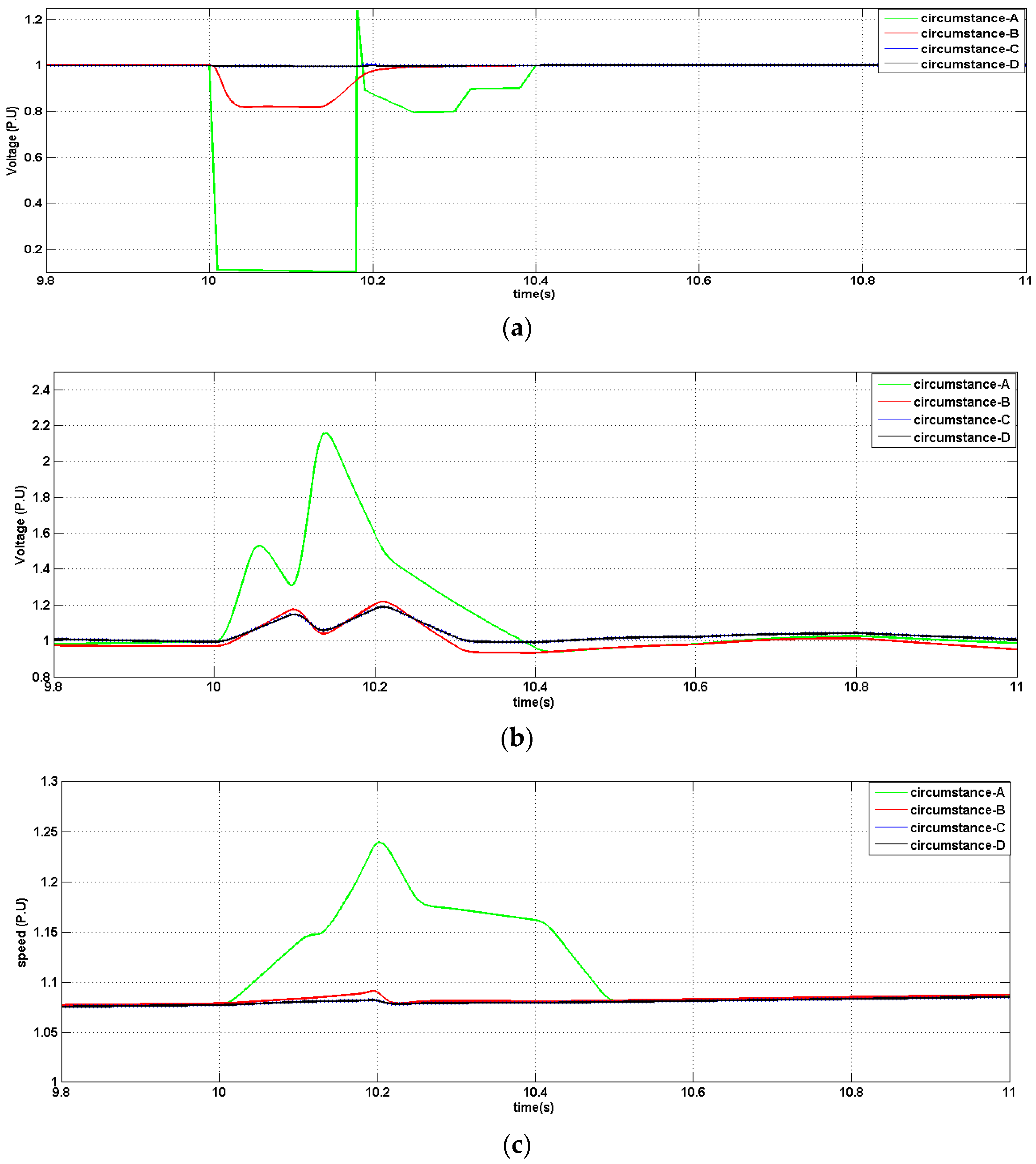
4. Simulation Results

Simulations are carried out for the power system shown in Figure 2d. A 3L-G fault is applied to power line 2 at t = 10 sec and cleared after 0.15 sec. the speed of wind is supposed to be steady and to demonstrate the capability of the suggested CBFCL. The system requirements used to perform the simulations are detailed in Appendix A. The simulations are executed for four circumstances:
  • Circumstance A: without FCL.
  • Circumstance B: with IBFCL.
  • Circumstance C: with CBFCL.
  • Circumstance D: with CBFCL using Fuzzy controller in drive train.

4.1. Variation of PCC Voltage, DC Link Voltage, Rotor Speed with Time

In this section, the variation of PCC voltage, DC link voltage, and rotor speed over time are analyzed for the four different circumstances.
Figure 3a shows the voltage profile of WF in all circumstances. When there is a voltage dip during the fault, there is a drop in electromagnetic torque and active power. The rotor speed increases because no power is given out during the fault, although there is still constant turbine mechanical power input. FCL offers a high voltage sag of 0.1 to 0.5 p.u., as shown in circumstance A. The DC reactor of the inductive bridge limits the voltage sag by offering a high impedance to the circuit. Without FCL, the voltage lowers dramatically, according to the results. The voltage of the terminal generator is restored with IBFCL during a fault, ensuring that the healthy line is not affected. The CBFCL ensures minimal voltage drop, while the fuzzy controller improves system reliability. Figure 3b shows the DC link voltages. Due to low voltage at the generator terminals during a voltage dip, the additional energy goes into charging the DC link capacitor. The stator-side converter at this stage is unable to pass the excess power to the grid and therefore DC link voltage at the back-to-back connected converters will rise rapidly. A rise is observed in DC link voltage during the fault, and it shows that the DC link voltage is effectively decreased with CBFCL as there is overvoltage without FCL. It is obvious that fuzzy controller gives more accuracy than traditional controller. Figure 3c shows the rotor speed of power system. During normal operation, the aerodynamic torque of the rotor acts on one end of the drive, but during a fault, electrical torque reduces on the other end. The rate of rising of rotor speed is important factor for stability of power system. In scenario A, the rate of rising speed is very high so that instability may occur. The rate of raising speed is restricted in scenarios B, C, and D, but CBFCL with fuzzy is more competent since it gives lesser oscillation and rapid stabilization. The minimum swing of rotor speed is achieved by choosing an optimum value on the resistor. For a better understanding, the results are presented in Table 2.

4.2. Variation of Rotor Current with Time for Different Circumstances

Figure 4 shows rotor currents in all scenarios. As the active power output is increased, the corresponding rotor output currents also increase. The elimination of an unusual rise in rotor current is important in protecting the RSC. In the case of CBFCL with fuzzy controller, the rotor currents are fully controlled. The transient spike of the rotor is undoubtedly limited at the start and finish of the fault period. The results are presented in Table 3 for a better understanding.

4.3. Variation of Reactive Power, Reactive Power Flow in Line, Active Power with Time

Figure 5a determines the total active power developed by the WF. When a voltage dip occurs, the active power reduces rapidly when the fault appears, while the reactive power quickly rises to a high value. In case A, it becomes zero during the fault, and is severely deformed afterward. The Power has less swing during the fault in scenario B. It is obvious that the power of the fault line is close to its pre-fault condition active power during the fault in scenario D.
Figure 5b demonstrates the reactive power transfer between grid and wind farm. The voltage at the PCC decreases as the reactive power increases. The reactive power absorbed is roughly −2.6 p.u. in scenario A, −0.7 p.u. in scenario B, too low in scenario C, and practically equal to zero in scenario D due to the instability of the system. Figure 5c demonstrates the flow of reactive power through line 1. The capacitor in the limiting impedance offers a good reduction of reactive power from the grid, which helps in the fast recovery of voltage. The reactive power taken from the grid through power line 1 are −2.5 and −0.5 respectively. In scenario C, it supports the system by generating reactive power via line 1 to back the grid connected point. The fuzzy controller, along with CBFCL, gives better reactive support to give the lowest voltage sag. For a better understanding, a summary of the results of the aforementioned cases is presented below (Table 4).

5. Conclusions

In the present study, a capacitive compensation technique is provided to a DFIG-based wind farm by designing a CBFCL with a fuzzy logic controller to limit the fault current during and after the fault for improving the LVRT performance. To test the performance of the designed controller, a simulation study is carried out by considering different operating conditions and the variations in PCC voltage, DC link voltage, rotor speed, rotor current, reactive power flow in line, and active power are observed. Being a non-linear controller, the fuzzy controller works effectively in minimizing these variations and maintains good reactive power flow according to the operating condition, thereby enhancing the system stability. From these results, the proposed CBFCL with fuzzy controller shows preferable LVRT performance than the traditional controller. In scenarios B, C, and D, the rate of speed increase is limited, but CBFCL with fuzzy is more capable since it produces less oscillation and faster stabilization. Rotor currents are fully controlled in CBFCL with the fuzzy controller. The transient spike of the rotor is unquestionably confined at the start and end of the fault period. The fuzzy controller, in combination with CBFCL, improves the responsiveness of the system to give lowest voltage sag. This analysis proves the efficacy of the fuzzy logic controller applied to the uncertain wind farms and provides improved power system transient stability under abnormal conditions. This study could be useful to extract reliable and good quality power from wind energy and may provide sustainable energy solutions.

Author Contributions

Writing-Original Draft, and Resources, A.P. and A.S.; Conceptualization, Methodology, Investigation, S.S.M. and R.D.; Review and Editing, F.P.G.M. and J.S.G. All authors have read and agreed to the published version of the manuscript.

Funding

The work reported herewith has been financially supported by the Dirección General de Universidades, Investigación e Innovación of Castilla-La Mancha, under Research Grant ProSeaWind project (Ref.: SBPLY/19/180501/000102).

Conflicts of Interest

The authors declare no conflict of interest.

Nomenclature

FCLfault current limiter
IBFCLinductive bridge fault current limiter
CBFCLcapacitive bridge fault current limiter
DFIGdoubly fed induction generator
FRTfault ride through
RSCrotor side converter
GSCgrid side converter
LVRTlow voltage ride through
STATCOMstatic synchronous compensator
WFwind farm
SDBRseries dynamic breaking resistor
PCCpoint of common coupling
DVRdynamic voltage restorer
UPICunified power inline controller
IGBTinsulated gate bipolar thyristor

Appendix A

Table A1. System requirement table.
Specifications of DFIGSpecifications of CBFCL and Grid
Nominal power2 MVANominal voltage66 KV
Nominal voltage690 VNominal frequency50 hz
Xls0.1022 puTransformer ratio690/66 KV
Xlr0.1123 puResistance(R)1.5 ohm
Rs0.0074 puReactance (X)3.4 ohm
Rr0.0061 puRsh10 ohm
H3 sCsh50 microF
Xm4.6321 puLD0.01 H
RSC of DFIGGSC of DFIG
Kp10.25Ki125Kp10.25Ki150
Kp21.3Ki2100Kp20.25Ki2120
Kp30.5Ki310Kp30.75Ki3100
Kp40.12Ki4125Kp40.5Ki4150

References

  1. IRENA. Global Renewables Outlook: Energy Transformation 2050. 2020. Available online: https://www.irena.org/publications/2020/Apr/Global-Renewables-Outlook-2020 (accessed on 25 March 2021).
  2. IRENA. Global Energy Transformation: A Roadmap to 2050. 2019. Available online: https://www.irena.org/publications/2019/Apr/Global-energy-transformation-A-roadmap-to-2050-2019Edition (accessed on 25 March 2021).
  3. Alegria, I.M.; Andreu, J.; Martin, J.L.; Ibanez, P.; Villate, J.L.; Camblong, H. Connection requirements for wind farms: A survey on technical requirements and regulation. Renew. Sustain. Energy Rev. 2007, 11, 1858–1872. [Google Scholar] [CrossRef]
  4. Tande, J.O.G. Exploitation of wind-energy resources in proximity to weak electric grids. Appl. Energy 2000, 65, 395–401. [Google Scholar] [CrossRef]
  5. Ellabban, O.; Abu-Rub, H.; Blaabjerg, F. Renewable energy resources: Current status, future prospects and their enabling technology. Renew. Sustain. Energy Rev. 2014, 39, 748–764. [Google Scholar] [CrossRef]
  6. Marugán, A.P.; Márquez, F.P.G.; Lev, B. Optimal decision-making via binary decision diagrams for investments under a risky environment. Int. J. Prod. Res. 2017, 55, 5271–5286. [Google Scholar] [CrossRef]
  7. Yuan, X. Overview of problems in large-scale wind turbines. J. Mod. Power Syst. Clean Energy Springer 2013, 1, 22–25. [Google Scholar] [CrossRef] [Green Version]
  8. Smith, J.C.; Milligan, M.R.; de Meo, E.A.; Parsons, B. Utility wind integration and operating impact state of the art. IEEE Trans. Power Syst. 2007, 22, 900–908. [Google Scholar] [CrossRef]
  9. Shi, L.; Dai, S.; Ni, Y.; Yao, L.; Bazargan, M. Transient stability of power systems with high penetration of DFIG based wind farms. Power Energy Soc. Gen. Meet. 2009, 1–6. [Google Scholar] [CrossRef]
  10. Qiao, W.; Harley, R.G. Effect of grid-connected DFIG wind turbines on power system transient stability. Power Energy Soc. Gen. Meet. 2008, 1–7. [Google Scholar] [CrossRef]
  11. Hossain, M.I.; Abido, M.A. SCIG Based Wind Energy Integrated Multiterminal MMC-HVDC Transmission Network. Sustainability 2020, 12, 3622. [Google Scholar] [CrossRef]
  12. Yousefi-Talouki, A.; Zalzar, S.; Pouresmaeil, E. Direct Power Control of Matrix Converter-Fed DFIG with Fixed Switching Frequency. Sustainability 2019, 11, 2604. [Google Scholar] [CrossRef] [Green Version]
  13. Li, M.; Wang, Y. Research on Frequency Fuzzy Adaptive Additional Inertial Control Strategy for D-PMSG Wind Turbine. Sustainability 2019, 11, 4241. [Google Scholar] [CrossRef] [Green Version]
  14. Eltamaly, A.M.; Al-Saud, M.; Sayed, K.; Abo-Khalil, A.G. Sensorless Active and Reactive Control for DFIG Wind Turbines Using Opposition-Based Learning Technique. Sustainability 2020, 12, 3583. [Google Scholar] [CrossRef]
  15. Abo-Khalil, A.G.; Eltamaly, A.M.; Praveen, P.R.; Alghamdi, A.S.; Tlili, I. A Sensorless Wind Speed and Rotor Position Control of PMSG in Wind Power Generation Systems. Sustainability 2020, 12, 8481. [Google Scholar] [CrossRef]
  16. Jalilian, A.; Naderi, S.B.; Negnevitsky, M.; Hagh, M.T.; Muttaqi, K. Controllable DC-link fault current limiter augmentation with DC chopper to improve fault ride-through of DFIG. IET Renew. Power Gener. 2017, 11, 313–324. [Google Scholar] [CrossRef]
  17. Qiao, W.; Venayagamoorthy, G.K.; Harley, R.G. Real-Time Implementation of a STATCOM on a Wind Farm Equipped with Doubly Fed Induction Generators. IEEE Trans. Ind. Appl. 2009, 45, 98–107. [Google Scholar] [CrossRef] [Green Version]
  18. Márquez, F.P.G.; Marugán, A.P.; Pérez, J.M.P.; Hillmansen, S.; Papaelias, M. Optimal Dynamic Analysis of Electrical/Electronic Components in Wind Turbines. Energies 2017, 10, 1111. [Google Scholar] [CrossRef] [Green Version]
  19. Márquez, F.P.G.; Ramírez, I.S.; Mohammadi-Ivatloo, B.; Marugán, A.P. Reliability Dynamic Analysis by Fault Trees and Binary Decision Diagrams. Information 2020, 11, 324. [Google Scholar] [CrossRef]
  20. Zhou, L.; Liu, J.; Zhou, S. Improved demagnetization control of a doubly-fed induction generator under balanced grid fault. IEEE Trans. Power Electron. 2015, 30, 6695–6705. [Google Scholar] [CrossRef]
  21. Hu, S.; Lin, X.; Kang, Y.; Zou, X. An improved low-voltage ride-through control strategy of doubly fed induction generator during grid faults. IEEE Trans. Power Electron. 2011, 26, 3653–3665. [Google Scholar] [CrossRef]
  22. Liu, S.; Bi, T.; Liu, Y. Theoretical Analysis on the Short-Circuit Current of Inverter-Interfaced Renewable Energy Generators with Fault-Ride-through Capability. Sustainability 2018, 10, 44. [Google Scholar] [CrossRef] [Green Version]
  23. Alam, M.S.; Abido, M.A.Y.; Hussein, A.E.-D.; El-Amin, I. Fault Ride through Capability Augmentation of a DFIG-Based Wind Integrated VSC-HVDC System with Non-Superconducting Fault Current Limiter. Sustainability 2019, 11, 1232. [Google Scholar] [CrossRef] [Green Version]
  24. Choi, N.; Park, B.; Cho, H.; Lee, B. Impact of Momentary Cessation Voltage Level in Inverter-Based Resources on Increasing the Short Circuit Current. Sustainability 2019, 11, 1153. [Google Scholar] [CrossRef] [Green Version]
  25. Shuai, X.; Yang, G.; Zhou, H.; Geng, H. An LVRT control strategy based on flux linkage tracking for DFIG-based WECS. IEEE Trans. Ind. Electron. 2013, 60, 2820–2832. [Google Scholar]
  26. Morshed, M.J.; Fekih, A. A new fault ride-through control for DFIG-based wind energy systems. Electr. Power Syst. Res. 2017, 146, 258–269. [Google Scholar] [CrossRef]
  27. Liu, X.; Han, Y.; Ch, W. Second-order sliding mode control for power optimisation of DFIG-based variable speed wind turbine. IET Renew. Power Gener. 2017, 11, 408–418. [Google Scholar] [CrossRef]
  28. Mohammadi, J.; Afsharnia, S.; Vaez-Zadeh, S.; Farhangi, S. Improved fault ride through strategy for doubly fed induction generator based wind turbines under both symmetrical and asymmetrical grid faults. IET Renew. Power Gener. 2016, 10, 1114–1122. [Google Scholar] [CrossRef]
  29. Pannell, G.; Atkinson, D.J.; Zahawi, B. Minimum-Threshold Crowbar for a Fault-Ride-Through Grid-Code-Compliant DFIG Wind Turbine. IEEE Trans. Energy Convers. 2010, 25, 750–759. [Google Scholar] [CrossRef]
  30. Marugán, A.P.; Márquez, F.P.G. Advanced analytics for detection and diagnosis of false alarms and faults: A real case study. Wind Energy 2019, 22, 1622–1635. [Google Scholar] [CrossRef]
  31. Gounder, Y.K.; Nanjundappan, D.; Boominathan, V. Enhancement of transient stability of distribution system with SCIG and DFIG based wind farms using STATCOM. IET Renew. Power Gener. 2016, 10, 1171–1180. [Google Scholar] [CrossRef]
  32. Tsili, M.; Papathanassiou, S. A Review of Grid Code Technical Requirements for Wind Farms. IET Renew. Power Gener. 2009, 3, 308–332. [Google Scholar] [CrossRef]
  33. Pannell, G.; Zahawi, B.; Atkinson, D.J.; Missailidis, P. Evaluation of the Performance of a DC-Link Brake Chopper as a DFIG Low-Voltage Fault-Ride-through Device. IEEE Trans. Energy Convers. 2013, 28, 535–542. [Google Scholar] [CrossRef]
  34. Huchel, Ł.; Moursi, M.S.E.; Zeineldin, H.H. A Parallel Capacitor Control Strategy for Enhanced FRT Capability of DFIG. IEEE Trans. Sustain. Energy 2015, 6, 303–312. [Google Scholar] [CrossRef]
  35. Okedu, K.E.; Muyeen, S.M.; Takahashi, R.; Tamura, J. Wind Farms Fault Ride through Using DFIG With New Protection Scheme. IEEE Trans. Sustain. Energy 2012, 3, 242–254. [Google Scholar] [CrossRef] [Green Version]
  36. Firouzi, M.; Gharehpetian, G.B.; Salami, Y. Active and reactive power control of wind farm for enhancement transient stability of multi-machine power system using UIPC. IET Renew. Power Gener. 2017, 11, 1246–1252. [Google Scholar] [CrossRef]
  37. Wessels, C.; Gebhardt, F.; Fuchs, F.W. Fault ride-through of a DFIG wind turbine using a dynamic voltage restorer during symmetrical and asymmetrical grid faults. IEEE Trans. Power Electron. 2017, 26, 807–815. [Google Scholar] [CrossRef] [Green Version]
  38. Ibrahim, A.O.; Nguyen, T.H.; Dong-Choon, L.; Su-Chang, L. A fault ride-through technique of DFIG wind turbine systems using dynamic voltage restorers. IEEE Trans. Energy Convers. 2011, 26, 871–882. [Google Scholar] [CrossRef]
  39. Okedu, K.E.; Muyeen, S.M.; Tamura, R.T.J. Conceptual Design and Evaluation of a Resistive-Type SFCL for Efficient Fault Ride Through in a DFIG. IEEE Trans. Appl. Supercond. 2016, 26. [Google Scholar] [CrossRef]
  40. Salami, Y.; Firouzi, M. Dynamic performance of wind farms with bridge-type superconducting fault current limiter in distribution grid. In Proceedings of the 2011 2nd International Conference on Electric Power and Energy Conversion Systems (EPECS), Sharjah, United Arab Emirates, 15–17 November 2011. [Google Scholar]
  41. Rashid, G.; Ali, M.H. Nonlinear Control-Based Modified BFCL for LVRT Capacity Enhancement of DFIG Based Wind Farm. IEEE Trans. Energy Convers. 2016. [Google Scholar] [CrossRef]
  42. Tapia, G.; Tapia, A.; Ostolaza, J.X. Proportional-integral regulator-based approach to wind farm reactive power management for secondary voltage control. IEEE Trans. Energy Convers. 2007, 22, 488–498. [Google Scholar] [CrossRef]
  43. Galdi, V.; Piccolo, A.; Siano, P. Exploiting maximum energy from variable speed wind power generation systems by using an adaptive Takagi-Sugeno-Kang fuzzy model. Energy Convers. Manag. 2009, 50, 413–421. [Google Scholar] [CrossRef]
  44. Calderaro, V.; Galdi, V.; Piccolo, A.; Siano, P. A fuzzy controller for maximum energy extraction from variable speed wind power generation systems. Electr. Power Syst. Res. 2008, 78, 1109–1118. [Google Scholar] [CrossRef]
  45. Galdi, V.; Piccolo, A.; Siano, P. Designing an adaptive fuzzy controller for maximum wind energy extraction. IEEE Trans. Energy Convers. 2008, 23, 559–569. [Google Scholar] [CrossRef]
  46. Marugán, A.P.; Márquez, F.P.G.; Lorente, J. Decision making process via binary decision diagram. Int. J. Manag. Sci. Eng. Manag. 2015, 10, 3–8. [Google Scholar] [CrossRef]
  47. Hua, S.Y.; Allen, T.J. Application of fuzzy logic in power systems. I. General introduction to fuzzy logic. Power Eng. J. 1997, 11, 219–222. [Google Scholar]
  48. Khezri, R.; Bevrani, H. Fuzzy-based coordinated control design for AVR and PSS in multi-machine power systems. In Proceedings of the 13th Iranian Conference on Fuzzy Systems, Qazvin, Iran, 27–29 August 2013; pp. 1–5. [Google Scholar]
  49. Chapman, S.J. Electric Machinery and Power System Fundamentals, 1st ed.; McGraw-Hill: New York, NY, USA, 2001. [Google Scholar]
  50. Bissey, S.; Jacques, S.; le Bunetel, J.-C. The Fuzzy Logic Method to Efficiently Optimize Electricity Consumption in Individual Housing. Energies 2017, 10, 1701. [Google Scholar] [CrossRef] [Green Version]
  51. Khezri, R.; Bevrani, H. Voltage performance enhancement of DFIG-based wind farms integrated in large-scale power systems: Coordinated AVR and PSS. Int. J. Electr. Power Energy Syst. 2015, 73, 400–410. [Google Scholar] [CrossRef]
Figure 1. (a) Simplified circuit diagram of DFIG, (b,c) RSC controller, (d,e) GSC control systems, and (f) pitch angle control with fuzzy.
Sustainability 13 06656 g001aSustainability 13 06656 g001b
Figure 2. (a) Normal operating mode. (b) Event at fault mode. (c) Test system equivalent circuit at the time of fault. (d) Simulated power system.
Sustainability 13 06656 g002
Figure 3. (a) Voltage vs time. (b) DC link voltage vs time. (c) Rotor speed vs time.
Sustainability 13 06656 g003
Figure 4. Rotor currents vs time in (a) circumstance A, (b) circumstance B, (c) circumstance C, and (d) circumstance D.
Sustainability 13 06656 g004aSustainability 13 06656 g004b
Figure 5. (a) Active power vs time. (b) Reactive power vs time. (c) Reactive power flow in line1 vs time.
Sustainability 13 06656 g005
Table 1. Fuzzy control rules.
NLNSZRPSPL
NLPSZRZRNSNS
NSPLPSZRZRPS
ZRZRZRNSZRZR
PSPSNSZRPSPS
PLNSZRPSZRNL
Table 2. Variation in PCC voltage, DC link voltage, and rotor speed with time in different circumstances.
Time
(Sec)
PCC Voltage (Vs) TimeDc Link Voltage (Vs) TimeRotor Speed (Vs) Time
ABCDABCDABCD
10111110.9511.071.0751.0751.0751.075
10.10.10.80.980.991.41.21.11.0751.151.081.0721.072
10.20.80.90.980.991.61.21.181.081.221.091.0721.072
10.30.80.950.9911.20.911.11.061.171.0721.0731.073
10.40.90.950.9910.90.911.0521.081.0751.0751.075
10.50.980.980.9910.90.911.031.0751.0751.0751.075
Table 3. Variation of rotor current with time for different circumstances.
Time
(Sec)
Rotor Current
ABCD
1031.41.021.01
10.121.31.021.01
10.21.51.21.011.01
10.31.31.051.011.01
10.41.2111
10.51111
Table 4. Variation in reactive power, reactive power flow in line, and active power with time in different circumstances.
Time
(Sec)
Wind Farm Reactive Power (Vs) TimeReactive Power Flow in Line (Vs) TimeWind Farm Active Power (Vs) Time
ABCDABCDABCD
10000.1450.13200001111
10.1000.1450.1320−0.50.50.3500.40.20.15
10.2−2−0.800−2−0.30.30.2321.51.21.05
10.3−2.5−0.200−1.7−0.10.20.151.60.80.60.5
10.4−2.2−0.100−1.5−0.10021.21.11.05
10.5−1.5−0.100−1.2−0.1001.81.20.950.98
Publisher’s Note: MDPI stays neutral with regard to jurisdictional claims in published maps and institutional affiliations.

