Abstract
In the present decade, research regarding solar thermal air heaters (SAHs) has noticed a continuous progression in thermo-hydraulic performance augmentation approaches. There now exists a wide variety of thermo-hydraulic performance augmentation approaches and researchers have designated various structures. Nevertheless, there seems to be no generalization to any of the approaches employed. The present numerical investigation reports on the thermo-hydraulic characteristics and thermal performance for flow through a varied length (full, medium, half, and short length) dimple solar air heater (SAH) tube. The study highlights recent developments on enhanced tubes to augment heat transfer in SAH. The influence of different length ratio, dimple height ratio (H), and pitch ratio (s) on thermo-hydraulic characteristics have been investigated in the Reynolds number (Re) range from 5000 to 25,000. Air is used as the working fluid. The commercial software ANSYS Fluent is used for simulation. The shear stress transport (SST) model is used as the turbulence model. Thermal energy transport coefficient is increased in the full-length dimple tube (FLDT), compared to the medium-length dimple tube (MLDT), half-length dimple tube (HLDT) and short-length dimple tube (SLDT). Similarly, the pitch ratio (s) has more influence on Nusselt number (Nu) compared to the dimple height ratio (H). The friction factor decreases with an increase in pitch ratio. Nu increases and f decreases with increasing Re for all combinations of H and s. Low s and higher H yields high enhancement of HT and PD. Integration of artificial roughness on the tube increases the values of Nu and f by 5.12 times and 77.23 times for H = 0.07, s = 1.0 at Re value of 5000 and 25,000, respectively, in regard to the plain tube. For all the tested cases, the thermo-hydraulic performances (η) are greater than unity.
1. Introduction
The last few decades have marked the acceptance of solar air heater (SAH) applications, which have flagged the way and highlighted the importance of solar energy use. Over the years, many investigators have talked, established, and contributed towards understanding and strengthening the fundamental aspects associated with solar air and water heating applications. Among these, air heating is a common practice for the utilization of solar energy. One of the notable merits of solar air heating is the lack of requirement for heat exchange from one working fluid to another working fluid, i.e., the air itself serves as the working fluid without any corrosion or sealing issues. Heat transfer improvement, in all forms of thermo-mechanical apparatus, is critical for the industry as it results in a decrease in size and weight, in addition to saving primary resources. Heat transfer augmentation techniques can be classified into two groups: (i) active methods, (ii) passive methods [1,2,3]. In the literature, there have been many laboratory experiments on heat augmentation techniques that utilize twisted tape as a passive technique [4,5,6,7,8,9,10,11]. Following this, the CFD modelling methodology was developed as a strong and useful method for better understanding complicated hydrodynamics [12,13,14,15,16,17,18] in many industrial processes, thanks to developments in computer hardware and software and the resulting increase in calculation speed.
Nakhchi and Esfahani [19] conducted a computational investigation for heat transfer enhancement inside a circular tube fitted with multiple perforated cylinders and revealed augmentation in heat transfer. The swirling flow and convective heat transfer in a circular tube fitted with loose-fit twisted tapes were numerically analysed by Eiamsa-ard et al. [20]. They discovered that minimizing the width of the twisted tape helped to minimize the pressure drop with a slight decrement in heat transfer coefficient, as well as thermal performance. Sivashanmugam et al. [21] used CFD to model heat transfer augmentation in a circular tube with a helical twist insert in both laminar and turbulent flow. Chang et al. [22] used broken twisted tape in their computational and experimental investigation and found that the given geometry of twisted tapes expands the spectrum of effective Re. Jayakumar et al. [23] compared CFD simulations to experiment convective heat transfers and pressure drops, and developed correlations for predicting the internal convective heat transfer coefficient in a double pipe helical heat exchanger. Nagarajan and Sivashanmugam [24] used computational fluid dynamics to model heat transfer augmentation and friction factor characteristics of a circular tube employed with a right-left helical twist insert having an 100 mm spacer. Saeidi et al. [25] performed a numerical analysis with the novel geometry of a spiral-type ground heat exchanger to reveal its thermal performance in COMSOL software. Mohammadshahi et al. [26] numerically reported on the usage of a single flexible fin inside a duct for heat transfer augmentation by varying parameters and revealed an increase in Nusselt number and a reduction in pressure loss. Bensaci et al. [27] numerically evaluated the optimal position of baffles for the best thermal performance and developed an experimental setup on the basis of CFD analysis. Xie et al. [28] performed CFD analysis for a dimpled (tear drop dimples) tube in ANSYS Fluent 17.2 for thermo-hydraulic performance and compared the results with the spherical and elliptical drops dimpled tube. In another investigation, Xie et al. [29] performed a similar study with an enhanced tube protrusion. Bhadouriya et al. [30] evaluated the thermo-hydraulics in a squared twisted tube for a wide range of the Reynold number, covering all flow regimes, and also developed a correlation for predicting the heat transfer and pressure drop. Muñoz-Esparza and Sanmiguel-Rojas [31] also performed simulations for evaluating the thermo-hydraulics inside a circular tube fitted with wire coils and revealed the effects of varying pitch on the thermal performance. Ağra et al. [32] carried out a simulation study for evaluating thermal performance inside an enhanced tube in a turbulent flow regime. The pressure drop and heat transfer coefficients of four helically corrugated tubes was investigated by Dong et al. [33] and the results obtained from the analysis were compared with the plain channel data to reveal the augmentation. Huang et al. [34] carried out a numerical investigation for the solar collector performance. Different geometrical modifications such as dimples, protrusions, and fins were used for the investigation. Heat transfer performance and friction factors of dimpled tubes were empirically studied by Chen et al. [35] and Vicente et al. [36], who developed a correlation for predicting the Nusselt number and friction factor. With a low-pressure loss penalty, the protrusions/dimples surface will increase the heat transfer rate. Cheraghi et al. [37] performed a computational investigation for thermal and flow performance inside a dimpled tube using three turbulence models, namely k-epsilon, k-omega, and the Reynolds stress model. A similar kind of investigation was also performed by Kumar et al. [38].
Over the years, several research and development initiatives have been made on the thermal performance enrichment of SAHs [39,40,41,42] After reviewing the various published articles on thermo-hydraulic performance enhancement, it may be summarized that the thermo-hydraulic performance of SAH depends on the change of artificial rough geometry [43,44,45,46]. In addition, for further enhancement in heat transfer, the potential differences in roughness have been utilized. Artificial roughness promotes a disturbance in the fluid domain by promoting swirl flow, as a result of which the thermal boundary layer is disturbed and then introduced to the secondary flow. The length of roughness of the tube also significantly influences the thermo-hydraulics performance of the SAH tube. However, very few authors reported on the length distribution as the influencing parameter. This factor is the motivation behind the present investigation. In the present study, a numerical investigation is performed for thermal and flow characteristics of the dimpled solar air heater tube. By varying the geometrical parameters of dimples, the maximum thermo-hydraulic performance will be evaluated. Air is taken as the working fluid medium and the Reynolds number will be varied from 5000 to 25,000 to cover a wide range of turbulent flow regimes. This study will provide improved assistance in design and development of an enhanced solar air heater tube for high thermal performance.
The following are the key goals of this numerical analysis:
- To investigate the influence of geometrical parameters on the thermal and flow characteristics inside a dimpled solar air heater tube.
- To investigate the influence of dimple height ratio and pitch ratio on heat transfer (HT), pressure drop (PD), and thermal performance factors (η).
- To find out the best overall thermal performance geometry of dimpled tube and compare with previous published work.
The applications of such SAHs are shown schematically in Figure 1a.
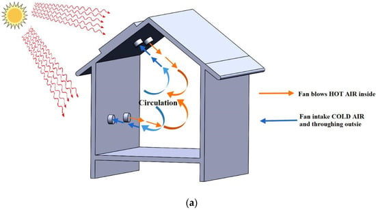
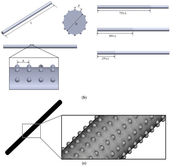
Figure 1.
(a) Application of solar air heater (b) schematic diagram of the computational domain, and (c) meshing–dimple tube.
2. Computational Study and Mathematical Model
Figure 1b illustrates two-and three-dimensional schematics of the computational domain with all the important parameters levelled. ANSYS Fluent commercial software is used for computational investigation. Four geometrical configurations of dimpled tube (diameter D)—namely full length dimpled tube (FLDT), medium length dimpled tube (MLDT), half-length dimpled tube (HLDT), and short length dimpled tube (SLDT), are designed for the investigation. The material of the tube is copper. FLDT have dimples all over the tube, MLDT contains dimples for ¾ length of tube, HLDT contains dimples for ½ length of tube and SLDT contains dimples for ¼ length of tube. Three different dimple height ratios (e/D = H = 0.07, 0.05, and 0.025) and three different pitch ratios (p/D = s = 1.0, 1.5, and 2.5) are used for parametric study, where ‘e’ is the dimple height and ‘p’ is the dimple pitch as shown in Figure 1a. All the important parameters are summarized in Table 1.

Table 1.
Geometrical Parameters.
It is important to choose the right turbulence model for specific simulation [12]. The turbulence model chosen is based on statistical requirements and reasonably reliable flow prediction. For the present study, SST k-omega turbulence model is chosen as the best suited model.
Incompressible, steady, and Newtonian fluid flow is investigated. Material properties are assumed to be constant throughout the numerical investigation. Viscous heating, buoyancy, and radiation effects are ignored. In the current study, Reynolds-averaged Navier–Stokes (RANS) method is used as the turbulence modelling structure. The RANS turbulence model, the two-equation SST model [6] is employed. The governing equations are presented below [6].
The equations for incompressible and steady turbulent flows are as follows:
Conservation of mass
Conservation of momentum
Conservation of energy
Equations of the turbulence model [6]
As the Navier–Stokes solver, the SIMPLE method is used in the present study. The double precision mode is applied. A second order upwind scheme is applied for convection terms. The convergence criteria for all the equations used in the present study were fixed to ten times lower compared to the normal settings.
At the inlet of the tube, a uniform velocity profile is used. Pressure outlet boundary condition is used at the outlet. A constant wall heat flux (q = 1.0 kW/m2) is used. Following Bhattacharyya et al. [6,12], the inlet TI of 5% was imposed.
The thermal performance factor (η) is calculated as the following relation [6,12]:
As per field synergy principle, synergy angle β is given by [47,48],
For average synergy angle [47,48],
3. Grid Independent Study and Validation
The accuracy of numerical calculations and the time it takes to compute them are primarily determined by the algorithm’s and grid’s rationality. As a consequence, the grid system would need to be debugged several times before it will provide results that are accurate and effective. Hence, in present investigation, four separate grids size are considered for the grid independence analysis, and the average Nusselt number (Nu), friction factor (f), and thermal performance (η) are described in Table 2. As a result, the grid of 2,902,789 nodes (grid 2) is used for all simulations in order to save simulation time and resources. Figure 1c shows the meshing of the geometry.

Table 2.
Grid independence study.
In Figure 2 and Figure 3, the results for Nu and f for the plain solar air heater tube from the current numerical analysis are compared with well-established correlations of Meyer et al. [16] and Blasius [36], respectively. The current numerical estimates are in strong harmony with the results of the comparisons, according to both confirmation studies. The data obtained from the simulation for the plain tube from the correlations with data range of +3.33% to +5.02%, 2.53% to 3.01% for the Nu and f, respectively.
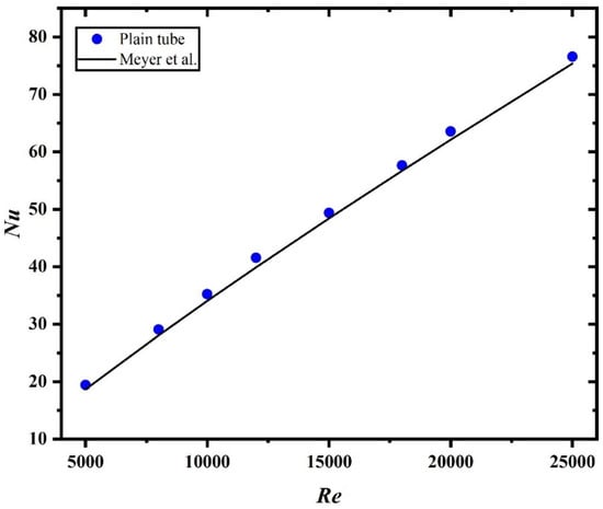
Figure 2.
Validation plain tube: Nusselt number.
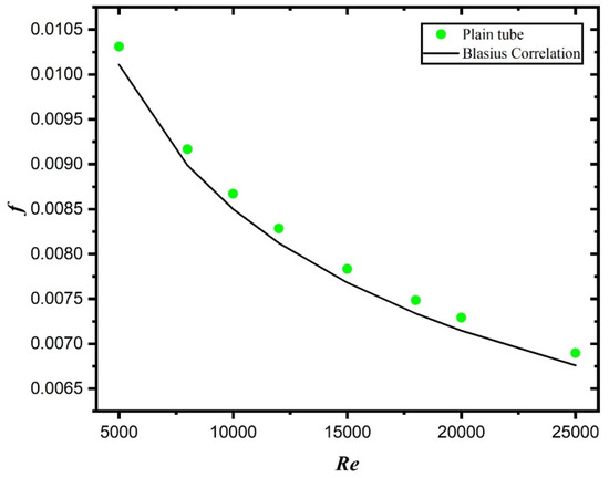
Figure 3.
Validation plain tube: friction factor.
4. Result and Discussion
A computational investigation was carried out on plain, and four types of dimpled solar air heater tubes, as mentioned earlier. To perform an extensive investigation, turbulent flow regime is taken into consideration and air is taken as the working fluid with the Reynolds number varied from 5000 to 25,000. The influence of parameters, such as the length of dimpled tube, dimple height ratio and pitch ratio on the HT and PD, is investigated.
Figure 4a–d presented that the Nu is the function of Re for constant pitch ratio s = 1.0 (Figure 4a), constant dimple height ratio H = 0.07 (Figure 4b), minimum and maximum twist ratio and angular cut (Figure 4c), and combined plot for all considered cases (Figure 4d).
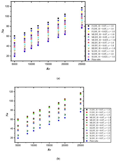
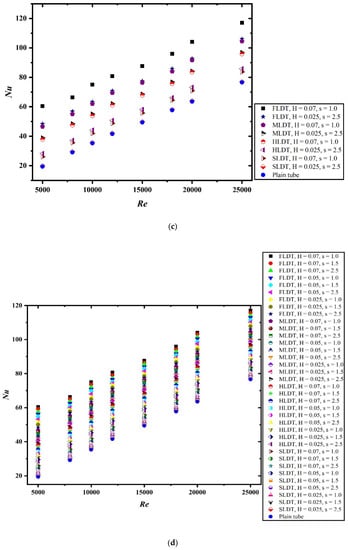
Figure 4.
Nusselt number as a function of Reynolds number: (a) at constant pitch ratio s = 1.0, (b) at constant dimple height ratio H = 0.07, (c) at maximum and minimum pitch ratio and dimple height ratio, and (d) at different pitch ratio and dimple height ratio.
From Figure 4a,b, one can see that the four tubes under consideration are distinct from one another in terms of thermal energy transport coefficient. The Nu of all dimpled tubes, as well as the plain tube, increases as the Re rises. The highest enhancement in Nu value is noted with FLDT having a dimple height ratio of 0.07 and a pitch ratio of 1.0 (Figure 4c). When compared with other tubes, FLDT shows the highest augmentation in Nu for all the geometrical parameters, then by MLDT, HLDT, and SLDT (Figure 4d). This is because the improved structure for the dimpled tubes could disrupt and split the thermal and hydrodynamic boundary layers, as well as increase mixing of the hot and cold fluids and thereby improve tube heat transfer due to the swirling nature of the flow.
It is worth noting that the enhancements of Nu for the FLDT dimpled tube are higher than that of the other dimpled tubes, as well as the plain tube at the same Re number (Figure 4a–d). The reason for higher HT is the formation of a longitudinal vortex formed in the flow field. The formation of vortices results in the alteration of the velocity and temperature field. It can be discussed that the frequency and magnitude of the recirculation flow at higher dimple height ratio is greater than that of lower dimple height ratio (Figure 4c).
The maximum two-fold enhancement in the HT occurs when the result of FLDT is compared with plain channel (Figure 4d). The length of the dimpled section in the tubes played important role in determining the thermal energy transport coefficient. The higher the length of the dimpled section, the higher the thermal energy transport coefficient rate because of an increased disturbance in the laminar sub layer of the boundary layer, due to the presence of more dimples. The dimples on the tube’s surface caused impingement and obstruction, causing the flow fluid to flush against the tube wall, as a result of which the thermal energy transport coefficient rate is improved. So, due of this phenomenon, the boundary layer is disrupted, the turbulent kinetic energy (TKE) and turbulent strength are increased, and the HT performance is enhanced.
The f is an important parameter while designing enhanced tubes. Pumping costs are affected by tube PD, and lower PD results in lower operating costs. It is obvious that the friction factor for all dimpled tubes varies with the rise in the Reynolds number in the same way that it does for smooth tubes.
A decreasing trend in the f is observed with the increase in the Re. As anticipated, FLDT shows the highest f followed by MLDT, HLDT and SLDT (Figure 5). For all kinds of dimple tubes, an increase in the value of the pitch ratio (s) and a decrease in the value of the dimple height ratio (H) result in the decreased value of f (Figure 5). It is clear from all figures (Figure 5a–d) that dimples having H = 0.07 and s = 1.0 show the highest-pressure penalty. This is due to an eddy formed by the dimples, which disrupted the flow field within the dimpled tube and is responsible for the increased PD.
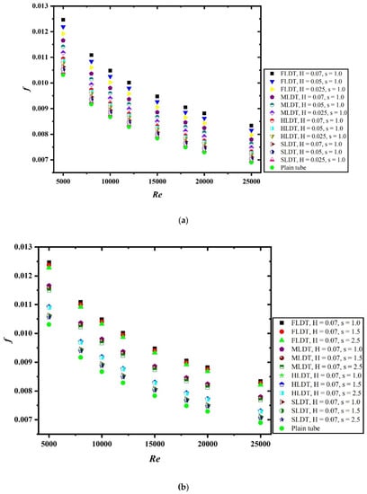
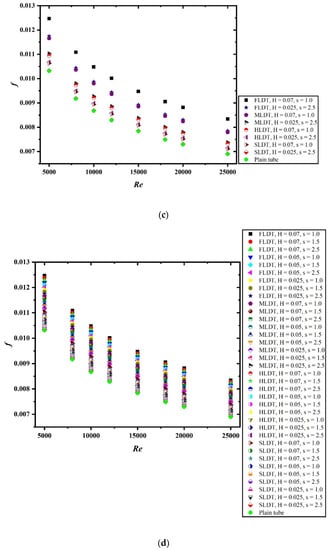
Figure 5.
Friction factor as a function of Reynolds number: (a) at constant pitch ratio s = 1.0, (b) at constant dimple height ratio H = 0.07, (c) at maximum and minimum pitch ratio and dimple height ratio, and (d) at different pitch ratio and dimple height ratio.
For constant pitch ratio in Figure 5a, a decrease in the dimple height ratio (H) results in decreased f, while for fixed value dimple height ratio (H) in Figure 5b, a decrease in pitch ratio (s) results in the increased value of f. The geometrical parameters and arrangement of dimples inside the tube significantly affect the f of dimpled tubes (Figure 5c). As the pitch ratio is increased, less deep dimples cover the surface of the tube, reducing the number of induced vortexes along the tube and resulting in a lower f for a given Re. In addition, the swirling of the fluid flow along the tube is also reduced significantly, as shown in Figure 5d.
The HT characteristics are presented in Figure 6 in terms of the Colburn j-factor, as a function of Re. Figure 6a–d shows the plots for j-factor. Colburn j-factor is the dimensionless factor which helps in determining the convective HT. Rather than a hypothese about transport phenomenon, it is focused on correlations and evidence.
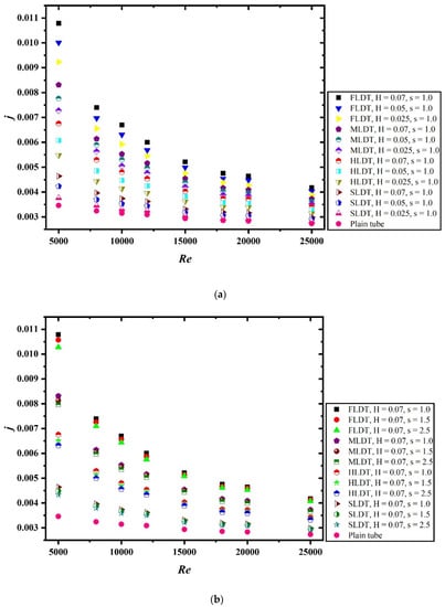
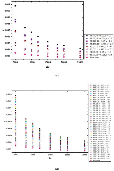
Figure 6.
Colburn j-factor as a function of Reynolds number: (a) at constant pitch ratio s = 1.0, (b) at constant dimple height ratio H = 0.07, (c) at maximum and minimum pitch ratio and dimple height ratio, and (d) at different pitch ratio and dimple height ratio.
It is clear from the figures (Figure 6a,b) that the highest Colburn j-factor is reported for FLDT, followed by MLDT, HLDT, and SLDT. A decreasing trend in j-factor is observed with an increase in Re for all tested tubes. An increase in the pitch ratio (s) and the decrease in dimple height ratio (H) result in the decreased value of j-factor. A significant rise in the value of j-factor is observed when compared with the plain tube (without dimple).
For a given Re, j-factor is increased with the decrease in pitch ratio (s) and an increase in dimple height ratio (H) (Figure 6c,d), and this is mainly due to the combined effects of common swirling flow by the dimple tube and the turbulence generated by the dimple type roughness along the edge of the tube, which leads to the destruction of the thermal boundary layer, creating better flow mixing between the fluids at the core and heating wall surface.
For better understanding the HT process and the effect of the dimple tube, the temperature contours at different locations of the tube are illustrated in Figure 7. Figure 7a shows the x/D locations of the tube. Figure 7b–e shows the temperature contours for FLDT, MLDT, HLDT, and SLDT, respectively. The dimple tube creates swirl flow which results in a higher thermal energy transport coefficient rate between fluid and the wall of the tube. The higher contact surface area of FLDT also resulted in a higher thermal energy transport coefficient rate.
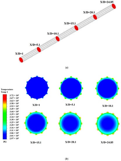
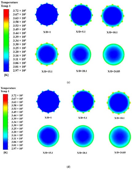
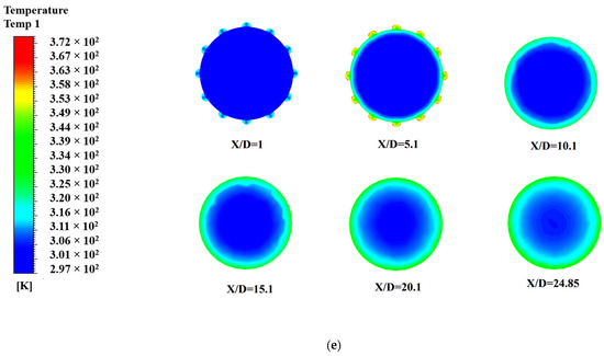
Figure 7.
Temperature contour plot: (a) x/D location, (b) FLDT, (c) MLDT, (d) HLDT, and (e) SLDT.
Figure 8 shows the velocity contour plot at different locations (Figure 7a) of the dimple tube. Figure 8a–d shows the velocity contours for FLDT, MLDT, HLDT and SLDT, respectively. One can see from the figures that the velocity is significantly sturdier near to the dimple roughness. Leading axial velocity near to the tube walls augment swirling and improved HT and the main reason behind this observation is the conservation of mass.
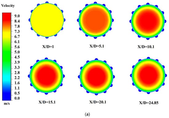
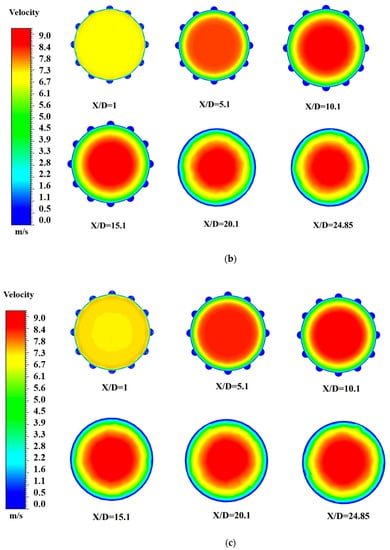
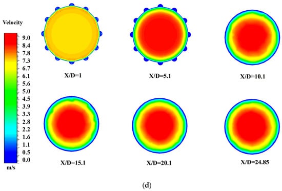
Figure 8.
Velocity contour plot (unit: m/s): (a) FLDT, (b) MLDT, (c) HLDT, and (d) SLDT.
Figure 9 shows the turbulent kinetic energy (TKE) contour plot at different locations (Figure 7a) of the dimple tube. Figure 9a–d shows the velocity contours for FLDT, MLDT, HLDT, and SLDT, respectively. As predicted from Figure 9b–d, secondary flow generated due to dimple height ratio which enhanced the turbulence level, resulting in improved TKE. One can also see from the figure that the TKE value is much higher in the case of dimple tube, as compared with plain tube (without dimple).
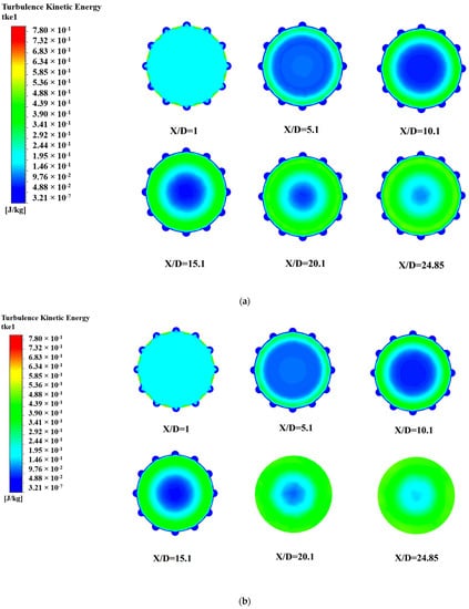
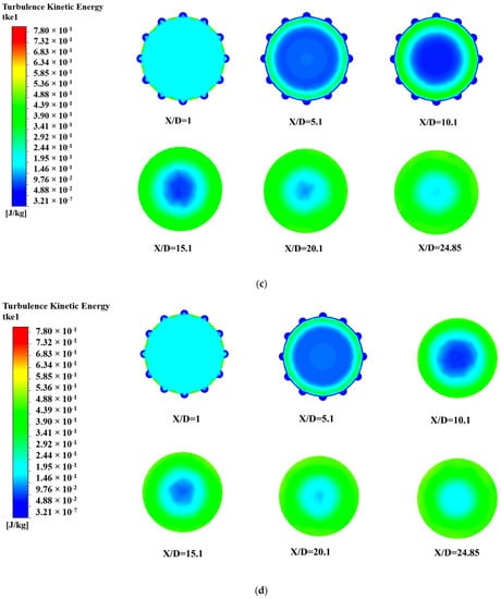
Figure 9.
Turbulent kinetic energy (TKE) contour plot: (a) FLDT, (b) MLDT, (c) HLDT, and (d) SLDT.
Equation (6) shows a parameter called thermal performance factor (η). The thermal performance (η) as a function of Re for various dimple tube configurations are illustrated in Figure 10a–d. It should be remembered that the thermal performance factor of different dimple tubes is comparable to the base case, which is a plain smooth tube with no dimple roughness and a thermal performance of unity (η = 1).
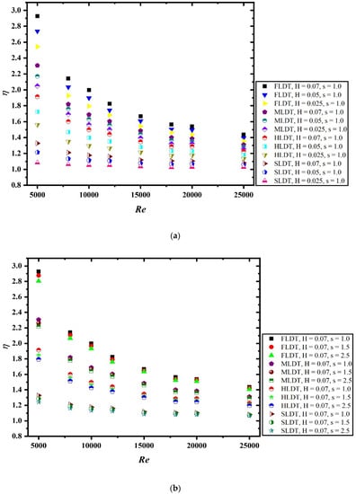
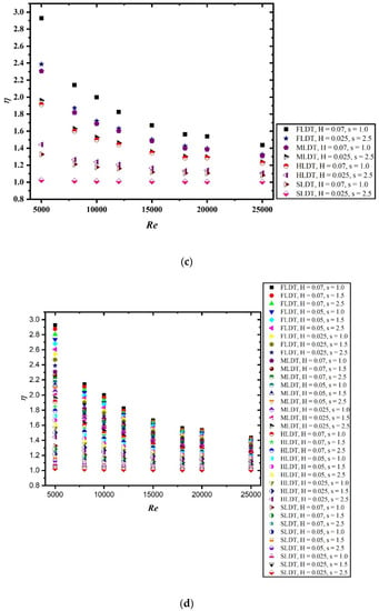
Figure 10.
Thermal performance factor as a function of Reynolds number: (a) at constant pitch ratio s = 1.0, (b) at constant dimple height ratio H = 0.07, (c) at maximum and minimum pitch ratio and dimple height ratio, and (d) at different pitch ratio and dimple height ratio.
By increasing the Re, the thermal performance factor of all tested cases decreases. However, it will remain higher than unity for all the cases, as illustrated in Figure 10. The highest thermal performance is reported for FLDT as having a pitch ratio (s) of 1.0 and a dimple height ratio (H) of 0.07. The enhancement in the thermal performance factor of FLDT is more than thrice when compared with SLDT. From the obtained graphs, it can be concluded that dimpled tubes performed better in terms of HT and pumping costs in the varied Re.
Figure 11 shows the comparison of the present numerical investigation with previously published research articles for thermal performance factors. It is clearly depicted from Figure 11 that the result from the present investigation is better when compared with the investigation of Wang et al. [41], Tang [42] and Mohammed et al. [43].
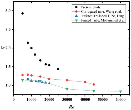
Figure 11.
Comparison plot of the present investigation with previous investigations.
The basic method for optimizing convective HT for a system is to improve the synergy between the velocity and the temperature gradient, according to the filed synergy theorem. As a result, this study will assist us in determining the exact enhancement produced by the dimples. Figure 12a–d illustrated the changes in synergy angle with an increase in the Re. A decreasing trend has been observed in all the graphs. The highest synergy angle is observed for the plain tube (without dimple roughness) which is very close to 90°, while the lowest synergy angle is observed for FLDT. It is also clear from all the figures that an increase in Re results in a decreased synergy angle. The size of dimples and the length of the dimpled section plays a significant role in determining the synergy angle.
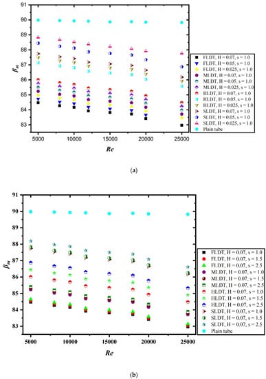
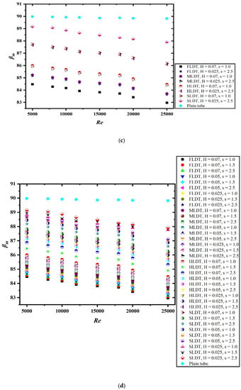
Figure 12.
Synergy angle as a function of Reynolds number: (a) at constant pitch ratio s = 1.0, (b) at constant dimple height ratio H = 0.07, (c) at maximum and minimum pitch ratio and dimple height ratio, and (d) at different pitch ratio and dimple height ratio.
5. Conclusions
Three-dimensional turbulent flow and convective HT in circular cross-section channels with different lengths of dimple tubes are numerically investigated. The effects of dimples height ratio, pitch ratio, and length of the dimpled tube on thermal-hydraulic performance are also discussed in a detailed manner. After analysing the various results, the following conclusion has been drawn:
- A numerical investigation with a dimpled tube of different lengths has been carried out. The dimpled tubes of all configurations performed significantly better when compared with the plain tube (without dimple roughness).
- Compared with MLDT, HLDT, and SLDT, the FLDT shows highest enhancement in HT and pressure penalty.
- Nu increases and f decreases with increasing Re for all combinations of H and s. Low s and higher H yields high enhancement of HT and PD.
- The integration of artificial roughness on the tube increases the values of Nu and f by 5.12 times and 77.23 times for H = 0.07, s = 1.0 at Re value of 5000 and 25,000, respectively, in respect to the plain tube.
- The thermal-hydraulic performance is significantly influenced by the geometric parameters considered during the numerical study. The increase in the value of pitch ratio results in lower value of thermal performance. Similarly, the decrease in the value of dimple height ratio also resulted in decreased performance.
- By comparing the thermal performance factor with previous investigations, it has been observed that the present study shows very significant augmentation.
- The outcome from this numerical investigation may be useful for the design of SAHs and HE.
Author Contributions
Conceptualization, M.W.A.; Data curation, M.W.A.; Formal analysis, M.W.A.; Funding acquisition, M.W.A. and B.S.; Investigation, M.W.A. and B.S.; Methodology, M.W.A. and B.S.; Project administration, M.W.A. and B.S.; Resources, B.S.; Software, B.S.; Supervision, B.S.; Validation, B.S.; Visualization, B.S.; Writing—Original draft, M.W.A.; Writing—Review & editing, B.S. All authors will be informed about each step of manuscript processing including submission, revision, revision reminder, etc. via emails from our system or assigned Assistant Editor. All authors have read and agreed to the published version of the manuscript.
Funding
This research was funded by Deanship of Scientific Research at King Faisal University, under DSR Annual Project (Grant No. 180103).
Institutional Review Board Statement
Not applicable.
Informed Consent Statement
Not applicable.
Data Availability Statement
Not applicable.
Acknowledgments
The authors acknowledge the Deanship of Scientific Research at King Faisal University for financial support under DSR Annual Project (Grant No. 180103).
Conflicts of Interest
The authors declare no conflict of interest.
Nomenclature
| A | crosee-sectional area |
| D | hydraulic diameter, m |
| e | depth, m |
| Fi | model blending functions |
| f | friction factor |
| h | heat transfer coefficient, W·m−2·K−1 |
| HT | heat transfer |
| H | dimple height ratio |
| j | Colburn j-factor |
| L | tube length, m |
| M | model constant |
| m | mass flow rate of working fluid, kg/s |
| Nu | Nusselt number |
| Nu0 | Nusselt number without turbulator |
| P | pitch |
| PD | pressure drop |
| Pκ | turbulent kinetic energy production term |
| Pr | molecular Prandtl number |
| Prturb | turbulent Prandtl number |
| q | heat flux, W·m−2 |
| Re | Reynolds number |
| Rw | average thermal resistance of wall, ohm |
| RANS | Reynolds averaged numerical simulation |
| SST | shear stress transport |
| S | pitch ratio |
| U | dimensionless variable of velocity |
| V | bulk velocity, m·s−1 |
| Greek Symbols | |
| α | molecular thermal diffusivity, m2·s−1 |
| βi | model constant |
| β | sygergy angle |
| σi | model constant |
| γ | intermittency |
| ΔP | pressure drop, Pa |
| η | thermo-hydraulic performance factor |
| µ | molecular dynamic viscosity, kg·m−1·s−1 |
| µturb | turbulent dynamic viscosity, kg·m−1·s−1 |
| ν | molecular kinematic viscosity, m2·s−1 |
| νturb | molecular kinematic viscosity, m2·s−1 |
| turbulence kinetic energy, m2·s−2 | |
| specific dissipation rate of , s−1 | |
| Θ | angular cut angle, degree |
| dimensionless variable of temperature | |
References
- Kanojiya, N.C.; Kriplani, V.M.; Walke, P.V. Heat Transfer Enhancement in Heat Exchangers With Inserts: A Review. Int. J. Eng. Res. Technol. 2014, 3, 494–500. [Google Scholar]
- Varun Saini, R.P.; Singal, S.K. A Review on Roughness Geometry Used in Solar Air Heaters. Sol. Energy 2007, 81, 1340–1350. [Google Scholar] [CrossRef]
- Gugulothu, R.; Reddy, K.V.K.; Somanchi, N.S.; Adithya, E.L. A Review on Enhancement of Heat Transfer Techniques. Mater. Today Proc. 2017, 4, 1051–1056. [Google Scholar] [CrossRef]
- Bhattacharyya, S. Fluid Flow and Heat Transfer in a Heat Exchanger Channel with Short-Length Twisted Tape Turbulator Inserts. Iran. J. Sci. Technol. Trans. Mech. Eng. 2020, 44, 217–227. [Google Scholar] [CrossRef]
- Saha, S.K.; Bhattacharyya, S.; Pal, P.K. Thermohydraulics of Laminar Flow of Viscous Oil through a Circular Tube Having Integral Axial Rib Roughness and Fitted with Center-Cleared Twisted-Tape. Exp. Therm. Fluid Sci. 2012, 41, 121–129. [Google Scholar] [CrossRef]
- Bhattacharyya, S.; Chattopadhyay, H.; Guin, A.; Benim, A.C. Investigation of Inclined Turbulators for Heat Transfer Enhancement in a Solar Air Heater. Heat Transf. Eng. 2019, 40, 1451–1460. [Google Scholar] [CrossRef]
- Bhattacharyya, S. The Effects of Short Length and Full Length Swirl Generators on Heat Transfer and Flow Fields in a Solar Air Heater Tube. J. Therm. Anal. Calorim. 2020, 140, 1355–1369. [Google Scholar] [CrossRef]
- Bhattacharyya, S.; Benim, A.C.; Chattopadhyay, H.; Banerjee, A. Experimental Heat Transfer Experimental Investigation of Heat Transfer Performance of Corrugated Tube with Spring Tape Inserts. Exp. Heat Transf. 2018, 32, 411–425. [Google Scholar] [CrossRef]
- Bhattacharyya, S.; Raghavendran, B.H.; Paul, A.R. The Effect of Circular Hole Spring Tape on the Turbulent Heat Transfer and Entropy Analysis in a Heat Exchanger Tube: An Experimental Study. Exp. Heat Transf. Online Publ. 2020, 8, 1–20. [Google Scholar] [CrossRef]
- Bhattacharyya, S.; Chattopadhyay, H.; Benim, A.C. Heat Transfer Enhancement of Laminar Flow of Ethylene Glycol through a Square Channel Fitted with Angular Cut Wavy Strip. Procedia Eng. 2016, 157, 19–28. [Google Scholar] [CrossRef]
- Bhattacharyya, S.; Sarkar, D.; Mahabaleshwar, U.S.; Soni, M.K.; Mohanraj, M. Experimental Study of Thermohydraulic Characteristics and Irreversibility Analysis of Novel Axial Corrugated Tube with Spring Tape Inserts. Eur. Phys. J. Appl. Phys. 2020, 92, 30901. [Google Scholar] [CrossRef]
- Bhattacharyya, S.; Chattopadhyay, H.; Benim, A.C. Computational Investigation of Heat Transfer Enhancement by Alternating Inclined Ribs in Tubular Heat Exchanger. Prog. Comput. Fluid Dyn. 2017, 17, 390–396. [Google Scholar] [CrossRef]
- Souayeh, B.; Bhattacharyya, S.; Hdhiri, N.; Alam, M.W. Heat and Fluid Flow Analysis and ANN-Based Prediction of a Novel Spring Corrugated Tape. Sustainability 2021, 13, 3023. [Google Scholar] [CrossRef]
- Mohamed Ibrahim, N.H.; Udayakumar, M.; Suresh, S.; Bhattacharyya, S.; Sharifpur, M. Coupling LES with soot model for the study of soot volume fraction in a turbulent diffusion jet flames at various Reynolds number configurations. Int. J. Numer. Methods Heat Fluid Flow Online Publ. 2020. [Google Scholar] [CrossRef]
- Bhattacharyya, S.; Dey, K.; Paul, A.R.; Biswas, R. A novel CFD analysis to minimize the spread of COVID-19 virus in hospital isolation room. Chaos Solitons Fractals 2020, 139, 110294. [Google Scholar] [CrossRef] [PubMed]
- Bhattacharyya, S.; Benim, A.C.; Bennacer, R.; Dey, K. Influence of Broken Twisted Tape on Heat Transfer Performance in Novel Axial Corrugated Tubes: Experimental and Numerical Study. Heat Transf. Eng. Online Publ. 2021, 1–22. [Google Scholar] [CrossRef]
- Everts, M.; Bhattacharyya, S.; Bashir, A.I.; Meyer, J.P. Heat transfer characteristics of assisting and opposing laminar flow through a vertical circular tube at low Reynolds numbers. Appl. Therm. Eng. 2020, 179, 115696. [Google Scholar] [CrossRef]
- Soni, M.K.; Tamar, N.; Bhattacharyya, S. Numerical simulation and parametric analysis of latent heat thermal energy storage system. J. Therm. Anal. Calorim. 2020, 141, 2511–2526. [Google Scholar] [CrossRef]
- Nakhchi, M.E.; Esfahani, J.A. Numerical Investigation of Heat Transfer Enhancement inside Heat Exchanger Tubes Fitted with Perforated Hollow Cylinders. Int. J. Therm. Sci. 2020, 147, 106153. [Google Scholar] [CrossRef]
- Eiamsa-ard, S.; Wongcharee, K.; Sripattanapipat, S. 3-D Numerical Simulation of Swirling Flow and Convective Heat Transfer in a Circular Tube Induced by Means of Loose-Fit Twisted Tapes. Int. Commun. Heat Mass Transf. 2009, 36, 947–955. [Google Scholar] [CrossRef]
- Sivashanmugam, P.; Nagarajan, P.K.; Suresh, S. Experimental Studies on Heat Transfer and Friction Factor Characteristics of Turbulent Flow through a Circular Tube Fitted with Right and Left Helical Screw-Tape Insert. Chem. Eng. Commun. 2008, 195, 977–987. [Google Scholar] [CrossRef]
- Chang, S.W.; Yang, T.L.; Liou, J.S. Heat Transfer and Pressure Drop in Tube with Broken Twisted Tape Insert. Exp. Therm. Fluid Sci. 2007, 32, 489–501. [Google Scholar] [CrossRef]
- Jayakumar, J.S.; Mahajani, S.M.; Mandal, J.C.; Vijayan, P.K.; Bhoi, R. Experimental and CFD Estimation of Heat Transfer in Helically Coiled Heat Exchangers. Chem. Eng. Res. Des. 2008, 86, 221–232. [Google Scholar] [CrossRef]
- Nagarajan, P.; Sivashanmugam, P. CFD Simulation of Heat Transfer Augmentation in a Circular Tube Fitted with Right-Left Helical Inserts with Spacer. Int. J. Chem. Eng. Res. 2009, 1, 1–11. [Google Scholar]
- Saeidi, R.; Noorollahi, Y.; Esfahanian, V. Numerical Simulation of a Novel Spiral Type Ground Heat Exchanger for Enhancing Heat Transfer Performance of Geothermal Heat Pump. Energy Convers. Manag. 2018, 168, 296–307. [Google Scholar] [CrossRef]
- Mohammadshahi, S.; Nili-Ahmadabadi, M.; Samsam-Khayani, H.; Salimpour, M.R. Numerical Study of a Vortex-Induced Vibration Technique for Passive Heat Transfer Enhancement in Internal Turbulent Flow. Eur. J. Mech. B Fluids 2018, 72, 103–113. [Google Scholar] [CrossRef]
- Bensaci, C.E.; Moummi, A.; Sanchez de la Flor, F.J.; Rodriguez Jara, E.A.; Rincon-Casado, A.; Ruiz-Pardo, A. Numerical and Experimental Study of the Heat Transfer and Hydraulic Performance of Solar Air Heaters with Different Baffle Positions. Renew. Energy 2020, 155, 1231–1244. [Google Scholar] [CrossRef]
- Xie, S.; Liang, Z.; Zhang, J.; Zhang, L.; Wang, Y.; Ding, H. Numerical Investigation on Flow and Heat Transfer in Dimpled Tube with Teardrop Dimples. Int. J. Heat Mass Transf. 2019, 131, 713–723. [Google Scholar] [CrossRef]
- Xie, S.; Liang, Z.; Zhang, L.; Wang, Y.; Ding, H.; Zhang, J. Numerical Investigation on Heat Transfer Performance and Flow Characteristics in Enhanced Tube with Dimples and Protrusions. Int. J. Heat Mass Transf. 2018, 122, 602–613. [Google Scholar] [CrossRef]
- Bhadouriya, R.; Agrawal, A.; Prabhu, S.V. International Journal of Heat and Mass Transfer Experimental and Numerical Study of Fluid Flow and Heat Transfer in a Twisted Square Duct. Heat Mass Transf. 2015, 82, 143–158. [Google Scholar] [CrossRef]
- Muñoz-Esparza, D.; Sanmiguel-Rojas, E. Numerical Simulations of the Laminar Flow in Pipes with Wire Coil Inserts. Comput. Fluids 2011, 44, 169–177. [Google Scholar] [CrossRef]
- Aǧra, Ö.; Demir, H.; Ataylmaz Özgür, S.; Kantaş, F.; Dalklç, A.S. Numerical Investigation of Heat Transfer and Pressure Drop in Enhanced Tubes. Int. Commun. Heat Mass Transf. 2011, 38, 1384–1391. [Google Scholar] [CrossRef]
- Dong, Y.; Huixiong, L.; Tingkuan, C. Pressure Drop, Heat Transfer and Performance of Single-Phase Turbulent Flow in Spirally Corrugated Tubes. Exp. Therm. Fluid Sci. 2001, 24, 131–138. [Google Scholar] [CrossRef]
- Huang, Z.; Yu, G.L.; Li, Z.Y.; Tao, W.Q. Numerical Study on Heat Transfer Enhancement in a Receiver Tube of Parabolic Trough Solar Collector with Dimples, Protrusions and Helical Fins. Energy Procedia 2015, 69, 1306–1316. [Google Scholar] [CrossRef]
- Chen, J.; Müller-Steinhagen, H.; Duffy, G.G. Heat Transfer Enhancement in Dimpled Tubes. Appl. Therm. Eng. 2001, 21, 535–547. [Google Scholar] [CrossRef]
- Vicente, P.G.; García, A.; Viedma, A. Heat Transfer and Pressure Drop for Low Reynolds Turbulent Flow in Helically Dimpled Tubes. Int. J. Heat Mass Transf. 2002, 45, 543–553. [Google Scholar] [CrossRef]
- Cheraghi, M.H.; Ameri, M.; Shahabadi, M. Numerical Study on the Heat Transfer Enhancement and Pressure Drop inside Deep Dimpled Tubes. Int. J. Heat Mass Transf. 2020, 147, 118845. [Google Scholar] [CrossRef]
- Kumar, A.; Maithani, R.; Suri, A.R.S. Numerical and Experimental Investigation of Enhancement of Heat Transfer in Dimpled Rib Heat Exchanger Tube. Heat Mass Transf. Stoffuebertragung 2017, 53, 3501–3516. [Google Scholar] [CrossRef]
- Bhattacharyya, S.; Vishwakarma, D.K.; Chakraborty, S.; Roy, R.; Issakhov, A.; Sharifpur, M. Turbulent Flow Heat Transfer through a Circular Tube with Novel Hybrid Grooved Tape Inserts: Thermohydraulic Analysis and Prediction by Applying Machine Learning Model. Sustainability 2021, 13, 3068. [Google Scholar] [CrossRef]
- Choudhary, V.; Kumar, M.; Patil, A.K. Experimental Investigation of Enhanced Performance of Pin Fin Heat Sink with Wings. Appl. Therm. Eng. 2019, 155, 546–562. [Google Scholar] [CrossRef]
- Wang, W.; Zhang, Y.; Li, B.; Li, Y. Numerical Investigation of Tube-Side Fully Developed Turbulent Flow and Heat Transfer in Outward Corrugated Tubes. Int. J. Heat Mass Transf. 2018, 116, 115–126. [Google Scholar] [CrossRef]
- Tang, X.; Dai, X.; Zhu, D. Experimental and Numerical Investigation of Convective Heat Transfer and Fluid Flow in Twisted Spiral Tube. Int. J. Heat Mass Transf. 2015, 90, 523–541. [Google Scholar] [CrossRef]
- Mohammed, H.A.; Abbas, A.K.; Sheriff, J.M. Influence of Geometrical Parameters and Forced Convective Heat Transfer in Transversely Corrugated Circular Tubes. Int. Commun. Heat Mass Transf. 2013, 44, 116–126. [Google Scholar] [CrossRef]
- Mosavati, B.; Mosavati, M.; Kowsary, F. Inverse boundary design solution in a combined radiating-free convecting furnace filled with participating medium containing specularly reflecting walls. Int. Commun. Heat Mass Transf. 2016, 76, 69–76. [Google Scholar] [CrossRef]
- Mosavati, B.; Mosavati, M.; Kowsary, F. Solution of radiative inverse boundary design problem in a combined radiating-free convecting furnace. Int. Commun. Heat Mass Transf. 2013, 45, 130–136. [Google Scholar] [CrossRef]
- Mosavati, M.; Kowsary, F.; Mosavati, B. A Novel, Noniterative Inverse Boundary Design Regularized Solution Technique Using the Backward Monte Carlo Method. J. Heat Transf. 2013, 135, 042701. [Google Scholar] [CrossRef]
- Fang Li, F.; Zhu, W.; He, H. Numerical optimization on microchannel flow and heat transfer performance based on field synergy principle. Int. J. Heat Mass Transf. 2019, 130, 375–385. [Google Scholar]
- Sun, X.Y.; Hua, L.J.; Dai, Y.J.; Ge, T.S.; Wang, R.Z. Field synergy analysis on heat and moisture transfer processes of desiccant coated heat exchanger. Int. J. Therm. Sci. 2021, 164, 106889. [Google Scholar] [CrossRef]
Publisher’s Note: MDPI stays neutral with regard to jurisdictional claims in published maps and institutional affiliations. |
© 2021 by the authors. Licensee MDPI, Basel, Switzerland. This article is an open access article distributed under the terms and conditions of the Creative Commons Attribution (CC BY) license (https://creativecommons.org/licenses/by/4.0/).