Article

A Unified Control Strategy of Distributed Generation for Grid-Connected and Islanded Operation Conditions Using an Artificial Neural Network

by
Karim M. El-Sharawy
1,*,
Hatem Y. Diab
2,*,
Mahmoud O. Abdelsalam
2,* and
Mostafa I. Marei
3,*
1
Department of Electrical and Control Engineering, Faculty of Engineering, Arab Academy for Science, Technology and Maritime Transport, Cairo 11799, Egypt
2
Department of Electrical Energy Engineering, Faculty of Engineering, Arab Academy for Science, Technology and Maritime Transport, Cairo 12577, Egypt
3
Electrical Power and Machines Department, Faculty of Engineering, Ain Shams University, Cairo 11517, Egypt
*
Authors to whom correspondence should be addressed.
Sustainability 2021, 13(11), 6388; https://doi.org/10.3390/su13116388
Submission received: 19 April 2021 / Revised: 18 May 2021 / Accepted: 24 May 2021 / Published: 4 June 2021

Abstract

:
This article presents a control strategy that enables both islanded and grid-tied operations of a three-phase inverter in distributed generation. This distributed generation (DG) is based on a dramatically evolved direct current (DC) source. A unified control strategy is introduced to operate the interface in either the isolated or grid-connected modes. The proposed control system is based on the instantaneous tracking of the active power flow in order to achieve current control in the grid-connected mode and retain the stability of the frequency using phase-locked loop (PLL) circuits at the point of common coupling (PCC), in addition to managing the reactive power supplied to the grid. On the other side, the proposed control system is also based on the instantaneous tracking of the voltage to achieve the voltage control in the standalone mode and retain the stability of the frequency by using another circuit including a special equation (wt = 2πft, f = 50 Hz). This utilization provides the ability to obtain voltage stability across the critical load. One benefit of the proposed control strategy is that the design of the controller remains unconverted for other operating conditions. The simulation results are added to evaluate the performance of the proposed control technology using a different method; the first method used basic proportional integration (PI) controllers, and the second method used adaptive proportional integration (PI) controllers, i.e., an Artificial Neural Network (ANN).

1. Introduction

Centralized power stations all over the world dominate the modern paradigm for power generation and supply. The generation of electricity in such plants generally uses as oil, coal, gas and nuclear power. The demand control network between stations and the end user resembles central electricity models. There are a few disadvantages to this single power plant scheme. The operating stresses in the existing transmission and distribution systems emerge from growing loads, which contribute to an increasing burden on electricity networks. Greenhouse gas emissions indicate a need for cleaner renewable energy sources. Alternative fuels like fuel cells, solar photovoltaic devices, wind turbines and biomass are used for distributed generation, as are microturbines and microgrids (DG). As a feasible solution to the above questions, these have been suggested.
New developments in DG technologies such as gas turbines, diesel engines, hydro turbines, and the wind energy conversion system (WECS) promise more efficient and greener power production [1,2]. Furthermore, DG is a feasible choice for maintaining high electrical efficiency because it can work in either a grid-tied or an islanded mode [3]. In the grid-tied mode, DG delivers energy to the utility and the local critical load [4]. However, DG can detach from the service and continue feeding critical local loads so that those critical loads will increase their power reliability [5]. The voltage is closely tightened with the tool in the grid-tied operation and regulated in the insular situation by the DG, such that both operating conditions are an important issue. DG would have to overcome the charge voltage as soon as possible in the event of the load voltage, which poses an obstacle to DG’s operation regarding the reduction of the load voltage transient when insulating [6].
DG is described as small generators linked to the load of the end user. They will lower the investment costs in transmission and distribution network improvements whilst also meeting power demand and providing consumers with high-quality and reliable electricity supply without emissions and harmful environmental impacts [7,8]. As far as Figure 1 is concerned, DG can usually be interpreted as small power plants built and run within a local loading center.
Electronic power conversion systems need to be built in order to monitor the energy supply and ensure the stable access of all of the DG’s sources to the current power systems [9]. In this manner, energy supply systems can also be regulated and conditioned. In particular, the typical connecting point between a DC bus and an AC environment is achieved with most DG sources, such as low power variable AC wind turbines, DC fuel cells, variable frequency AC Micro Turbines, PV panels, and electric power as a DC voltage or converted to a DC voltage.
DG has multiple benefits and advantages, such as voltage support and power supply diversification, as well as the reduction of transmission and distribution network losses, increased electricity efficiency, and transmission and distribution capability release, among others, which will boost the grid without installing or modifying any current transmission/distribution infrastructure.
When interacting with DG systems, some problems and questions should be discussed. Particularly when the design is made for power distribution support, and when the principles both the grid-connected (GC) and the stand-alone (SA) state are included, some considerations need to be made. Each DG device is usually run in the grid-connected mode, in which power is supplied or delivered to a pre-set grid, i.e., the new grid-synchronized control mode [10,11,12].
Once the principal grid is cut off from DG system by a grid breakdown, the DG system will sense the insulation and turn to a voltage control model to provide voltage stability to the local critical loads [13,14], which is the basis for the operation of a standalone operation, or the insulation mode. It is trendy that the grid-connected (GC) mode should also be able to operate in stand-alone mode [15]. This means that the grid is also accessible. New problems are being identified in DG control techniques for voltage adjustment in standby mode, current grid mode adjustment, and automated grid failure detection.
DG will provide advantages both for the customers and the utilities in delivery networks, and transmission networks are limited elsewhere. DG [16,17,18,19,20,21,22,23,24] is projected to reduce greenhouse gas emissions in relation to traditional generations because it increases the number of renewable energy supply consumers, and DG could act as a replacement for transmission and distribution infrastructure investments, which will help to prevent congestion in the current transmission networks. Thus, a high productivity network is achieved. The installation’s energy quality can be grown by preparing and operating the production and storage appropriately.
Additionally, the need for new facilities can be postponed or replaced by delivery generations due to the opportunities of incorporation into houses; DG construction also takes place in the same place as the demand. In these situations, network strengthening might not be required if the production performance is combined with the demand—like air conditioning demand in hot regions—whilst the generation remains in the same order of magnitude as the demand.
In addition, normal power grid development may be delayed as a result of increasing the demand using DG, minimizing transmittance and distribution losses, resulting in a reduction of the energy transmission from a centralized plant and reduced transmission and distribution costs, which are a large part of the total electricity costs as a result of production units and power generation units. Moreover, it leads to a high voltage transient link between distributed generators and power networks. Moreover, problems exist with DG’s provision of nonlinear local loads, such as electrical furnaces, semi-conductive equipment, solders and inductive furnace systems. Its reason for generating the harmonic components of the voltages and currents and its power supply to critics cannot achieve the optimum efficiency of DG when a grid breakdown occurs. It still takes a long time for the power grid to be repaired, before the DG is ready and in a state of service. In addition, during the transition from the island service, the inrush grid current is attached to the grid. During transmission from a grid-bonded to a standalone service, the output voltage of the DG may become unstable with poor dynamical efficiency.
In this case, the inverters are often controlled by a voltage control loop as a voltage source; the consistency of the load voltage during the transmission between the operating conditions can also be maintained at a constant, and this control can also be imposed on the DG in order to ensure power sharing among the DG and the grid-tying utility [25,26,27]. The bandwidth of the external power control circuit is also much lower than that of the voltage circuit, and therefore has low dynamic performance.
In addition, the inrush grid current occurs through a phase-locked loop (PLL) and Simulated Inductance during transmission from the standalone condition to the grid-tied condition. The grid current is also directly uncontrolled [28]. The hybrid voltage and the mode regulation of the current mode is an effective solution for DG, in which two different control sets are used [29,30,31,32,33,34,35,36,37,38,39,40,41,42,43,44,45,46,47,48,49].
The inverter is operated by other controls in the standalone operation as a voltage source whilst the current source is controlled by a grid-tying controller set. The voltage loop, and the current loop as a hybrid device in this method, can then obtain a pleasant dynamic output.
Moreover, the grid operation directly controls the output current and almost eliminates the inrush grid current. When the DG’s operating state is converted, the hybrid voltage and power control system must be switched automatically through the controllers. When insulated, an automatic switch is attached to the voltage control model in order to prevent the loading voltage being either clamped by a utility or regulated by the DG, and the time for the transmission between the operational conditions will be calculated for the insulation detection phase. The speed and precision of the insulation detection technique is therefore a major problem in this approach, which provides a high-quality waveform of the load voltage [50,51,52,53]. Other problems with the solution are the grid current waveform efficiency and the charge voltage under a nonlinear local load. The output current of DG is normally desired to be strictly sinusoidal in the grid-tying operation [54], as the nonlinear local load is fed the harmonic components of the charge current flow entirely through the utility. A single-phase DG injects a harmonic current into the grid current utility, as represented in [55], in order to reduce the harmonic parts of the grid current. The DG controller strengthens the voltage control model in order to change the harmonic frequency resistance and then decrease the harmonic current into the power supply [56].
In a standalone operation, a nonlinear load will detract from the voltage [57], and several controls and a multi-loop control system have been suggested to obtain a high quality of the waveform for the load voltage, including [57], a resonant controller [58,59], and a control sliding mode [60]. However, in grid-tied operations, the focus of the existing control policies and dealing with a nonlinear local load in DG, in particular, focuses on either grid current efficiency elsewhere or load tension in the island operation (VL), and both of these are seldom improved using a single management approach.
In this study, a coherent control strategy is addressed which removes the previously mentioned limitations and shortcomings. The DG is advised to run in a standalone or grid-bundled service with this control system. However, the controllers used by each operating environment change the strategies simply. This control strategy manages voltage and frequency in an island operating condition of the DG interface using the voltage monitoring procedure for each device, which is performed by PI controls and a special circuit integrated in proportion instead of the Phase Locked Loop (PLL). The proposed control strategy even extends the fuel economy in grid-tied operation conditions.
With a view to the elimination of the harmonic component of the grid current in the grid operation, DG introduces harmonic power into the grid and thus reduces the harmonic component of the grid current and prevents ripples by means of L-C Filter architecture to produce the purest wave shapes possible.
The proposed control strategy based on an adaptive PI neural network-based controller is presented in this paper to gain high efficiency during microgrid operation and reduce the transient across the critical load in order to achieve the maximum stability in different operating conditions. First, the conventional control method through Basic PI controllers is presented and tested. Secondly, the proposed method through adaptive PI controllers based on Neural Networks is explained in detail and conducted on the same test system.
The proposed adaptive PI neural network strategy successfully achieves results better than the first method, as shown later in the simulation results section. This paper is organized as follows: Section 2 shows the description of the system under study, while Section 3 presents the proposed control strategy and algorithm. In Section 4, the simulation results are presented and accordingly, in Section 5, the discussion is carried out. Finally, in Section 6, the final conclusions are drawn.

2. Description System

2.1. General Elements in the Main Power Network

Because of their postponement function of supporting the power network, a broad proposal is made for linked distributed generators. In addition, many technologies, natural and saving products are included with the interface between the distributed generators and the main grid system. As interference, the utility network is made greater than the grid characteristics by decreasing the lack [61]. However, small turbines work as a part of the relation generator amplitude; as an illustration of distributed generator products, they possibly increase. Tiny, quality turbines are smaller in scale [62].
The inverter is not classically a 50/60 Hz Sine Wave AC when clamped together with the small turbine. Thus, to obtain the essential agreements on the main network as seen in Figure 2, a static energy converter should be interfaced with this topology. The integration of a DC source and the inverter into the low voltage utility network applies to all of the power network. The head elements of this integration method are to transform the non-fixed voltage and frequency delivered by the DC source into a frequency constant indicating the voltage level of the network. This system is linked to the DC–AC transformation network [63]. A three-step inverter and a DC source connected to the main network compose this network integration. The critical load and inverter are secured by means of a DC connector consisting of a condenser for the reduction of the harmonics.
DG is a small part of the built DG power from 25 KW to 300 KW with high rotational speeds, as micro turbines (up to 120,000 rpm). The low-volume and high productivity of these micro turbines is shown in [64]. In order to ensure continuity with the energy grid, this technology must be combined with a static power converter, the direct current source and the interface attached to the micro turbine, which do not output a traditional 50/60 Hz sine-wave ac. For interfaces between the micro turbine and the low-voltage distribution system, many power electronic systems are used. Instead of the variable frequency and tensile frequency, as seen in Figure 1, DC sources and the inverter are received at a constant frequency signal on a net voltage basis. This state usually uses the DC–AC conversion method [65].
As the grid fails, the interface structure includes a three-phase inverter attached to the DC source to provide critical loads. Related is the critical load and inverter by an LC filter which consists of an inductance of 1 × 10⁻³ mH and a capacitor of 500 × 10−6 to reduce the ripples; furthermore, the critical load is R = 2 ohm and L = 10 × 10−2. In addition, the DC Source is equal to 1 KV.

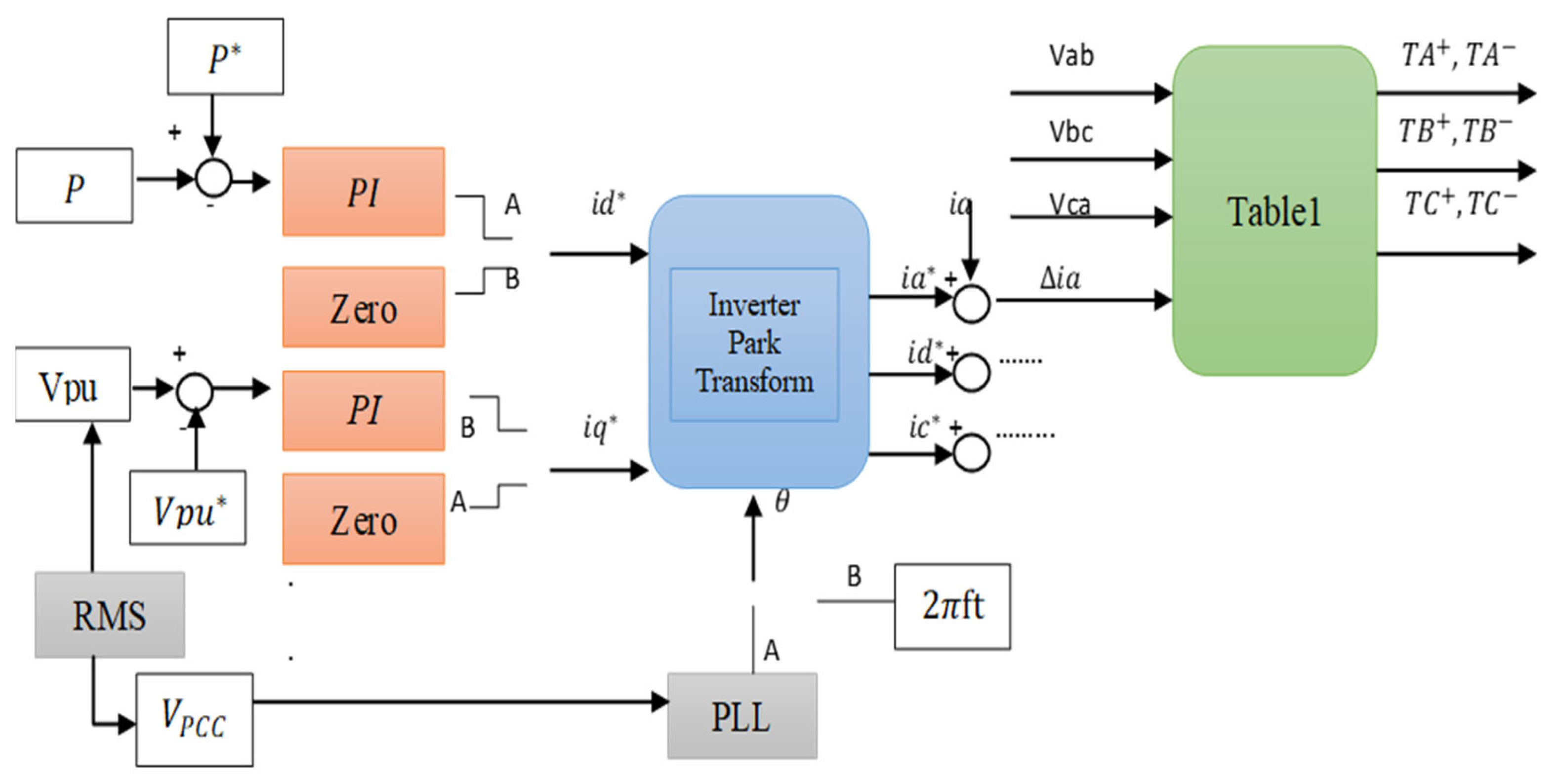
2.2. Proposed Control Method

A standalone or grid-bundled approach is described that begins with the DG. However, the controllers are dynamic [65] and linked with all of the operating conditions. The technique used for the monitoring organizes the voltage around the terminal and the DG interface frequency in the insulating state. The control system is used not only to control the active power of the DG interface but also to manage the grid’s reactive energy supply. The interface network can also be structured at the joint connection point (PCC) or at the unit power factor (UPF). In the park transformation, the structure of the utilized control strategy is coordinated, which requires the immediate step angle of the PCC [66].
In the standalone or grid-connected operation of the control method, three two-position choices are convenient for i d * ,   i q * , and θ. For the standalone condition, the three selectors are switched to position B.
For the grid-tied condition, the id* and θ selectors are turned to position A, while the   i q * selector is connected to select the UPF (unified power factor) or the voltage regulation mode. The result of the current i q * is selected based on the desired condition. For the UPF condition, zero is assigned to i q * through the coordinates of its selector switch at position A. For the Standalone condition, in this situation, to obtain the voltage regulation result, the current i q * is specified to the result of the voltage regulation circuit (position B). For the UPF condition [66], zero is specified to i d *   through the coordinates of its selector switch, as shown in Figure 3.

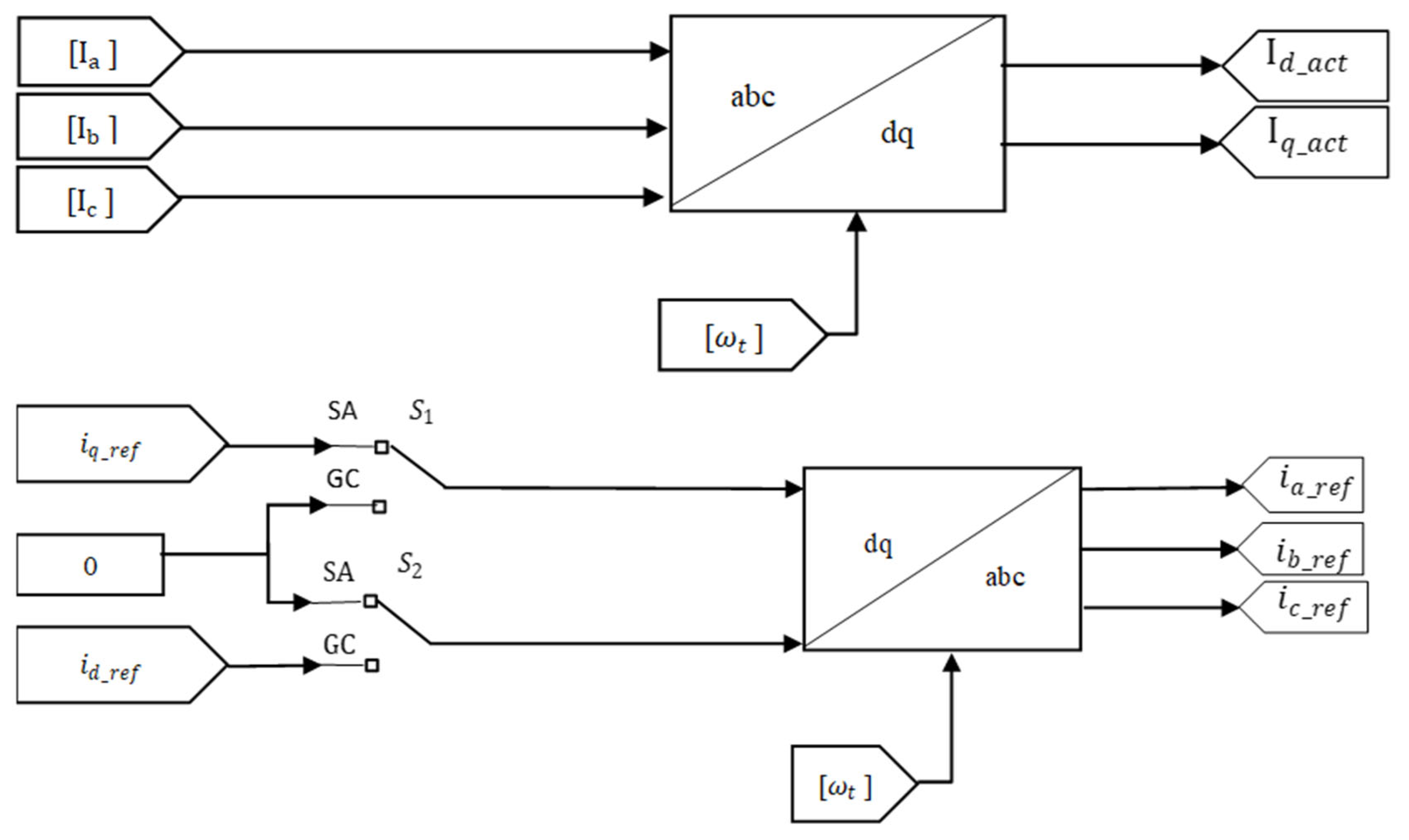
2.2.1. The Park Transform Calculations

As shown in Figure 4, describing the issues of the used controller for all conditions of implementation, the inverse Park transform IPT and Park Transform PT [66], shown through Equations (1) and (2), is taken to obtain the reference currents i a * , i b * and i c * :
[ i a * i b * i c * ] = [ 1 0 0.5 3 2 0.5 3 2 ]   *   [ c o s θ s i n θ s i n θ c o s θ ]   *   [ i d * i q * ]
[ i d * i q * ] = 2 3   *   [   1 0.5 0.5 0 3 2 3 2   ]   *   [ c o s θ s i n θ s i n θ c o s θ ]   *   [ i a * i b * i c * ]

2.2.2. The Phase Angle Calculation

When the grid is linked, the selectors can be switched when an icon detection programmer is used and when the angle θ required by the Park transform is believed to be grid-based, depending on the circuit breaker mode that binds the grid to the PCC. This specifies the prerequisite for the PLL network to be linked. The key issues of this controller in the Standalone Condition are to coordinate the load voltage at the needed level and to sustain the frequency at its certain value. The DG must supply the load with a special current, in accordance with the rated voltage shown in Figure 5, in order to achieve a certain voltage level [66]. Substituting i d *   = 0 and θ = 2πft into Equation (3) results in the equations shown:
i a * = i q * sin ( 2 Π f t ) i b * = i q * sin ( 2 Π f t 2 Π 3 ) i c * = i q * sin ( 2 Π f t + 2 Π 3 )
The current i q * is the result from the voltage regulation circuit. For the standalone condition, the selector switches.

3. Control System and Algorithm

3.1. Basic Proportional Integration (PI) Controller

3.1.1. The Reference Calculations

At Grid-Tied Conditions

A basic proportional-integral (PI) controller is connected to detect the error between the actual value active power (P-act.) within the range 10–250 KW, and the reference result of the active power (P-ref), which is set at (80 KW). The result from the PI controller is the needed direct current reference value for voltage compensation (id-ref). In order to achieve suitable tracking, the actual value active power to the reference value of the active power must be set by the proportional gain (Kp-d) and integration gain (Ki-d) to reach the minimum error between the input values [66], as shown in Figure 6. Here, suitable tracking is achieved based on the following items: the setting of the proportional gain (Kp-d) at 9 × 10⁻¹² and the setting of the integration gain (Ki-d) at 9 × 10⁻³.

At Standalone Conditions

A basic proportional-integral (PI) controller is connected to detect the error between the root mean square value of the voltage per unit within the range 0.1–1Pu and the needed reference value of the voltage level, which is set at (1Pu) ( V P U * ). The result from the PI controller is the needed quadrature current reference result for the voltage compensation (iq-ref.). In order to achieve the suitable tracking of the actual value of the voltage per unit ( V P U )   to the reference value of the voltage per unit ( V P U * ) , the proportional gain (Kp-q) and the integration gain (Ki-q) must be set to reach the minimum error between the input values [66], as shown in Figure 7. Here, suitable tracking is achieved based on the following items: the setting of the proportional gain (Kp-q) at 725 × 10−4, and the setting of the integration gain (Ki-q) at 13.63 × 10⁻¹.

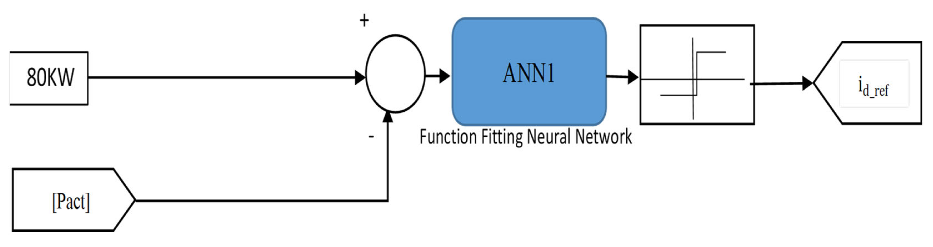
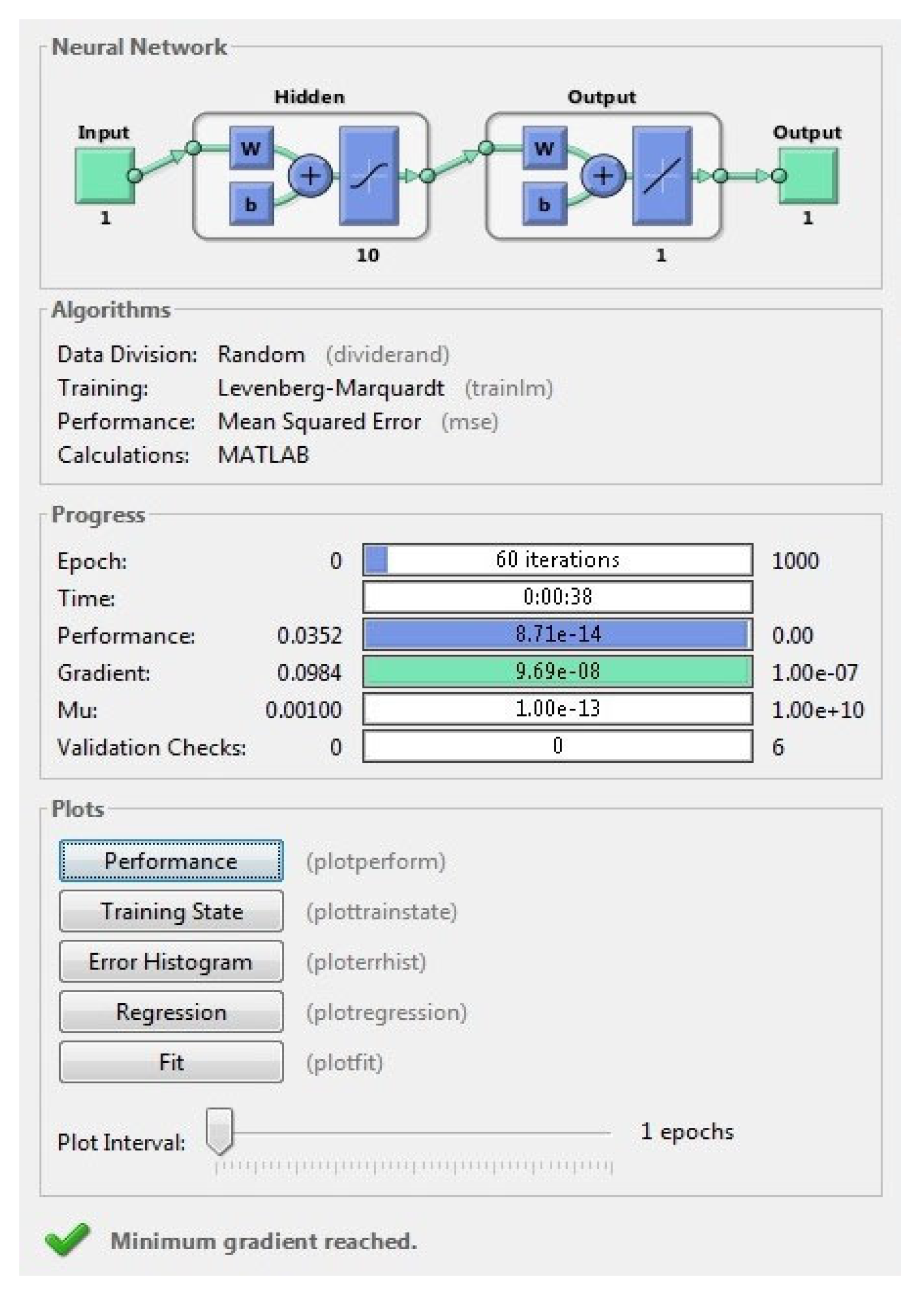
3.2. Adaptive Proportional Integration Using an Artificial Neural Network (ANN)

The way that a human brain designs a preventative model is an artificial neural network (ANN). ANNs are always at the center of profound awareness. Deep neural networks (DNNs), which are capable of handling unlabeled variables, are reliant on input symmetries or group variables, and whether they are grouped with marked variables for practice. The set of input products is distinguished for each neuron. This means that digital objects can be taken using supervised or unmonitored preparation as an indication of the clustering of the variables and a value. The network chooses a neuron from the outcome.
There are three layers to the structure of a neural-network algorithm:
  • The input layer: this enters past variables’ values into the next layer.
  • The hidden layer: this is a main issue of a neural network. It has complex functions which generate predictors. A group of nodes in the hidden layer mean that the neurons show the math functions which edit the input variables.
  • The output layer: this is the model’s prediction, in which the predictions made in the hidden layer are composed to obtain the final layer.
A machine learning scheme depending on artificial neural networks for vertical handover has been shown to obtain communication and the optimum-tied call mode [67].
The performance outputs reflect a perceived increase in QoS via voice, as well as variable utilities. Based on physical group optimization [68], a special network identification algorithm is recommended. The findings show that the structure’s application decreases the machine complexity and time dramatically. An adaptive factor change algorithm [69] is seen in an artificial neural network, dependent upon the strategy for the creation of the network access. The study of the simulation revealed that the plan allows users to easily reach the final network, and output variance can be effectively ignored. A multi-layered feed forward algorithm of the neural network is used to decide the user device’s optimal target network for the transfer of the current calling steps. Figure 8 reflects the structure in neural networks of a suggested transfer algorithm. Four layers included the suggested algorithm. Four input neurons—such as the currency expense, speed, RSSI, data rate, and output layer—are part of the first layer. The two hidden layers consist of numerous nodes which use hyperbolic tangent sigmoid functions.
The suggested vertical transfer standard utility uses different inputs for smooth communication through various heterogeneous wireless technologies, such as the currency cost, signal power, speed and the data rate of the mobile stations. The velocity refers to the acceleration of the moving terminal and the RSSI (indicator of the obtained signal strength) refers to the network’s service area availability.

3.2.1. The Reference Calculations

At Grid-Tied Conditions

An Adaptive PI Controller Artificial Neural Network (ANN1) is connected to detect the error between the actual value active power (P-act.) within the range 10–250 KW and the reference value of the active power (P-ref), which is set at 80 KW. The result from the Adaptive PI Controller Artificial Neural Network (ANN1) is the needed direct current reference value for the voltage compensation (id-ref). The structure of the Artificial Neural Network (ANN1) is as shown in Figure 9.
The design of the pact control of the ANN1 algorithm is used for more than 1000 data points (input and output). The training data are generated with help of the PI controller and stored the data in the workspace. Finally, the observed data are used to provide training in the MATLAB environment. The neural network model is presented in Figure 10. The ANN1 model’s best performance value is 9.3647 × 10⁻¹⁴, as presented in Figure 11. The ANN1 model gradient (9.6935 × 10⁻⁸), Mu 1 × 10⁻¹³ and the validation check are presented in Figure 12. The trained ANN1 model error value is presented in Figure 13. The regression of the ANN1 model’s trained validation values are presented in Figure 14. Finally, the fitness function of the ANN1 model is presented in Figure 15.

At Standalone Conditions

An Adaptive PI Controller Artificial Neural Network (ANN2) is connected to detect the error between the root mean square result of the voltage per unit within range 0.1–1Pu and the needed reference value of the voltage level, which is set at 1Pu ( V P U * ) . The result from the Adaptive PI Controller Artificial Neural Network (ANN2) is the needed quadrature current reference result for the voltage compensation (iq-ref.). The structure of artificial neural network (ANN2) is shown in Figure 16.
The design of the V P U   control of the ANN2 algorithm is used for more than 2000 data points (input and output). The training data are generated with the help of the PI controller and store the data in the workspace. Finally, the observed data are used to provide the training in MATLAB environment. The neural network model is presented in Figure 17. The ANN2 model’s best performance value is 6.278 × 10⁻¹⁴, as presented in Figure 18. the fitness function of the ANN2 model is presented in Figure 19. The regression of the (ANN2) model’s trained validation values are presented in Figure 20. The ANN2 model gradient (9.8462 × 10⁻⁸), Mu 1 × 10⁻¹³ and validation check are presented in Figure 21. Finally, the trained (ANN2) model error value is presented in Figure 22.

4. Simulation Results

4.1. At Grid-Connected Mode

In this case, we start from 0 s to 0.4 s and from 0.75 s to 1 s using the C.B condition, which is the certain periodic time that the critical load is supplied by the main grid; during this condition, the PLL is actively connected using the voltage grid, sets the frequency, and is clamped with the grid frequency at 50 HZ as frequency stability; the actual value is tracked to the reference value of the active power at 80 KW, and the reference of the quadrature current is equal to zero; otherwise, the reference of the direct current is a certain value generated from the active power tracking circuit and the voltage load is equal to 230 V per phase-a. In addition, the active value of the direct and quadrature current is tracked to its reference value.

4.2. At Standalone Mode

In this case we start from 0.4 s to 0.75 s using the C.B condition, which is a limited periodic time in which the critical load is fed through the DC source, which is converted to AC through a three phase inverter and connected with the LC Filter to avoid the ripples that are generated from the inverter operation; during this condition, the switch will cross over the PLL and connect to a certain circuit included in the special equation (wt = 2πft, f = 50 HZ) to achieve the frequency stability, the same as in the grid-connected mode; the active value is tracked to the reference value of the voltage per unit at 1.0pu. and the reference of the direct current is equal zero; otherwise, the reference of quadrature current is a certain value generated from the voltage per unit tracking circuit, and the voltage load is equal to 230 V per phase-a. In addition, the active value of the direct and quadrature current is tracked to its reference value.

4.3. At Transferring from One Condition to Another

This statement analysis is critical to supervise the dynamic implementations of the recommended control structure within the transfer from one state to another. The voltage regulation circuit is applicable, and P * is obtained at 80 kW. Both the base and switching critical loads are clamped with the PCC. The CB is opened at t = 0.4 s and then reconnected at t = 0.75 s to disconnect the utility from the PCC within this periodic time. The dynamic characteristics of the used integrated network occur within the transference between the grid-tied state and the standalone state. The voltage per unit is closely organized at 1.0pu.

4.4. The Simulation Results Using Basic PI Controllers

4.4.1. At Transferring Conditions from Grid-Connected to Standalone

In this case, especially at a certain time t = 0.4 s, the circuit breaker is switched off to switch from the grid-connected to the islanded mode; then, some issues are monitored and noted within this limited and very short period as per the following issues. Firstly, the load voltage per phase-a is decreased by a small value—50 V approximately—and secondly, the voltage per unit is reduced from 0.7pu. to 0.6pu. Thirdly, the load current per phase-a is decreased to 0.04 A, and fourthly, the direct current is equal to zero and the quadrature current is increased gradually to reach 0.2 A. Fifthly, the phase angel wt. is increased within 120 to 220, and the actual value of the active power is decreased to zero.

4.4.2. At Transferring Conditions from Standalone to Grid-Connected

In this case, especially at a certain time t = 0.75 s, the circuit breaker is switched on to switch from the islanded to the grid-connected mode; then, some issues are monitored and noted within this limited and very short period as per the following issues. Firstly, the load voltage per phase-a is damped down instantaneously as a quick transient and re-increased by a large value reach to 320 V; secondly, the voltage per unit is re-increased from 0.6pu. to 0.78pu. and re-decreased again to 0.7pu.
Thirdly, the load current per phase-a is quickly damped down as a transient and re increased by more than the previous value to reach 0.06 A. Fourthly, the direct current is over the transient by a large value, reaching 0.3 A, and the quadrature current is decreased to a zero value; fifth, the phase angel wt. is reduced to a zero value and the actual value of the active power overshoots from zero to 480 KW, and starts to decrease gradually to 80 KW as the reference value, as shown in Figure 23, Figure 24, Figure 25, Figure 26, Figure 27, Figure 28, Figure 29, Figure 30, Figure 31 and Figure 32, and the total harmonic distortion in several operation modes are shown in Figure 33 and Figure 34.

4.5. The Simulation Results Using an Adaptive PI Controller Artificial Neural Network (ANN)

A small voltage dip and rise occurred during the switching instance of the CB. The reference current, iq-ref, is created from the voltage control structure. Within the periodic time of grid-tied operation, iq-ref is critical to feed the reactive power to the main grid and handle the voltage at unity. Furthermore, iq-ref is raised to feed the overall load current (active and reactive elements) and then to generate a unity terminal voltage level when the grid is in failure. The reactive and active power items provided from the DG interface are schemed. The active power item is raised during standalone condition is start happened. An issue was expected because only 10 KW was provided to the load from the DG interface in the grid-tied state, and the rest was provided from the utility. When in standalone mode, the reactive power fed through the DG interface is decreased through an ignored result because the grid-tied controller was steadily feeding the load reactive power to control the voltage at unity. This simple variation is the same as an output of the correction that the voltage controller receives similar to the power loss because of the connection between the distribution bus and the PCC. As such, the vanishing of the grid-tied state is an issue for this small reactive power variation between the grid-tied and standalone states. The phase of the voltage at the PCC, which is familiar with its phase angle within the switching instant currents’ IL are clear and pure waveforms. These outputs detect a high-dynamic feedback and the critical characteristics of the recommended unified control structure for the following of the load current and voltage control within the two stats of implementation and within the transfer between them.

4.5.1. At Transferring Conditions from Grid-Connected to Standalone

In this case, especially at a certain time, t = 0.4 s, the circuit breaker is switched off to switch from the grid-connected to islanded mode; then, there are some issues which are monitored and noted within this limited and very short period, as per the following issues. Firstly, the load voltage per phase-a is decreased by a small value, less than 50 V, and secondly, the voltage per unit is reduced from 0.72pu. to 0.65pu.
Thirdly, the load current per phase-a is decreased to 0.028 A, and fourthly, the direct current is approximately equal to zero (especially over-damped to zero and slightly raised to 0.02 A) and the quadrature current is increased from zero to 0.1A. Fifthly, the phase angle wt. is increased within 120 to 220, and the actual value of the active power is decreased to 20 KW as a quick transient, and then re-increased by a small value and fixed at 40 KW.

4.5.2. At Transferring Conditions from Standalone to Grid-Connected

In this case, especially at certain time, t = 0.75 s, the circuit breaker is switched on to switch from the islanded to grid-connected mode; then, there are some issues which are monitored and noted within this limited and very short period, as per the following. Firstly, the load voltage per phase-a is increased by small value and reached 320 V. Secondly, the voltage per unit is re-increased from 0.65pu. to 0.72pu. Thirdly, the load current per phase-a is increased to 0.03 A, and fourthly, the direct current is over-transient by a certain value, reaches 0.07 A as a very quick response, and is re-reduced gradually to 0.045 A, reaching a stable value at 0.05 A; the quadrature current is decreased to a zero value. Fifth, the phase angel wt. is reduced to a zero value and the actual value of the active power is raised up from 40 KW to 90 KW as a quick transient and decreased to 80 KW as a reference value, as shown in Figure 35, Figure 36, Figure 37, Figure 38, Figure 39, Figure 40, Figure 41, Figure 42, Figure 43 and Figure 44; the total harmonic distortions in several operation modes are shown in Figure 45 and Figure 46.

5. Discussion

5.1. General Comments about the Achieved Results

As shown in Section 4, which presented the achieved results based on basic PI controllers and Artificial Neural Networks, after accurate study, the proposed control model achieved voltage, frequency and power stability in grid-connected mode, islanded mode and transferring mode. On the other side, the stability results using adaptive PI controller Artificial Neural were better than the stability results achieved using Basic PI controllers, in addition, the Phase Locked Loop achieved frequency stability in the two methods.

5.2. Variations of the Control Parameters

The proposed control strategy will work on the system under study for power and frequency stability under different values of inputs. However, if major modifications are made to the system under study, the proposed control model may need some modifications to its parameter settings. This is expected because the PI and neural network structure design are mainly based on the current system under study.

5.3. Implementation Applied to Complex Problems

The control design and the algorithms for the adaptive PI controller Artificial Neural Networks which were used in this paper are a major control strategy that can be applied in large scale and complex problems, but in this case, the structure of the Artificial Neural Network and its design and parameters must be changed according to its new scale and the new problem, as mentioned in the previous comment. The proposed problem in this paper is practical, as there are different cases in real life that need the proposed model and control strategy to obtain voltage and frequency stability during the transfer from grid-connected mode to islanded mode and otherwise, in order to retain the efficiency of the sensitive and critical loads which can be effected negatively in its life time, and its efficiency due to the multi transients across it during the transferring modes.

6. Conclusions

In this paper, a unified control strategy was proposed for three-phase inverter interfacing DG to operate in both islanded and grid-tied modes. This strategy offers instantaneous transfer between the different operation conditions while maintaining the voltage and frequency references. In addition, the adaptive proportional integration (PI) controller based on an Artificial Neural Network (ANN) was utilized for the online tracking of the active power and voltage, where the reference direct and quadrature current estimation is based on the ANN instead of classical PI controllers. The proposed control strategy was compared with the conventional PI controller when applied to same test system, and better results were achieved. It was noted that the task of the proposed method was achieved successfully, and that the gain voltage and frequency stability in the standalone mode were maintained. In addition, the gain power and frequency stability were achieved in the grid-connected mode by using the phase-locked loop and power tracking within its conditions. Several simulation states were executed to adjust the dynamic implementation of the proposed control structure for the different operation conditions of the current-controlled structure using the MATLAB software package. The results achieved with the proposed adaptive PI-ANN based controller showed that it can form an efficient solution for modern power system control problems.

Author Contributions

Conceptualization, M.I.M.; methodology, K.M.E.-S.; software, K.M.E.-S.; validation, H.Y.D.; formal analysis, M.O.A.; investigation, H.Y.D.; resources, H.Y.D.; data curation, K.M.E.-S.; writing—original draft preparation, K.M.E.-S.; writing—review and editing, M.O.A.; visualization, M.O.A.; supervision, M.I.M.; project administration, M.I.M. All authors have read and agreed to the published version of the manuscript.

Funding

This research received no external funding.

Institutional Review Board Statement

Not applicable.

Informed Consent Statement

Not applicable.

Data Availability Statement

Not applicable.

Conflicts of Interest

The authors declare no conflict of interests.

References

  1. Mozina, C.J. Impact of Green Power Distributed Generation. IEEE Ind. Appl. Mag. 2010, 16, 55–62. [Google Scholar] [CrossRef]
  2. Massucco, S.; Pitto, A.; Silvestro, F. A Gas Turbine Model for Studies on Distributed Generation Penetration into Distribution Networks. IEEE Trans. Power Syst. 2010, 26, 992–999. [Google Scholar] [CrossRef]
  3. Lasseter, R.H. Microgrids and Distributed Generation. J. Energy Eng. 2007, 133, 144–149. [Google Scholar] [CrossRef]
  4. Ekonomou, L.; Fotis, G.P.; Vita, V.; Mladenov, V. Distributed generation islanding effect on distribution networks and end user loads using the master-slave islanding method. J. Power Energy Eng. 2016, 4, 1–24. [Google Scholar] [CrossRef] [Green Version]
  5. IEEE. Standard for Interconnecting Distributed Resources with Electric Power Systems. IEEE Stand. 2003, 1547, 2003. [Google Scholar]
  6. Guerrero, J.M.; Hang, L.; Uceda, J. Control of Distributed Uninterruptible Power Supply Systems. IEEE Trans. Ind. Electron. 2008, 55, 2845–2859. [Google Scholar] [CrossRef] [Green Version]
  7. Ajaja, A. Reinventing electric distribution. IEEE Potentials 2010, 29, 29–31. [Google Scholar] [CrossRef]
  8. Stewart, E.; Tumilty, R.; Fletcher, J.; Lutz, A.; Ault, G.; McDonald, J. Analysis of a Distributed Grid-Connected Fuel Cell During Fault Conditions. IEEE Trans. Power Syst. 2009, 25, 497–505. [Google Scholar] [CrossRef]
  9. Vasquez, J.C.; Guerrero, J.M.; Luna, A.; Rodríguez, P.; Teodorescu, R. Adaptive Droop Control Applied to Voltage-Source Inverters Operating in Grid- Connected and Islanded Modes. Ind. Electron. IEEE Trans. 2009, 56, 4088–4096. [Google Scholar] [CrossRef]
  10. Wu, C.-S.; Liao, H.; Wang, Y.-B.; Peng, Y.-C.; Xu, H.-H. Design of intelligent utility-interactive inverter with AI detection. In Proceedings of the Electric Utility Deregulation and Restructuring and Power Technologies, DRPT 2008, Nanjing, China, 6–9 April 2008; pp. 2012–2017. [Google Scholar]
  11. Franceschini, G.; Lorenzani, E.; Tassoni, C.; Bellini, A. Synchronous Reference Frame Grid Current Control for Single-phase Photovoltaic Converters. In Proceedings of the Industry Applications Society Annual Meeting, 2008, IAS ‘08, Edmonton, AB, Canada, 5–9 October 2008; IEEE: New York, NY, USA, 2008; pp. 1–7. [Google Scholar]
  12. Selvaraj, J.; Rahim, N.A. Multilevel Inverter for Grid-Connected PV System Employing Digital PI Controller. IEEE Trans. Ind. Electron. 2008, 56, 149–158. [Google Scholar] [CrossRef]
  13. Green, T.C.; Prodanovic, M. Control of inverter-based microgrids. Electr. Power Syst. Res. 2007, 77, 1204–1213. [Google Scholar] [CrossRef] [Green Version]
  14. Haque, M.E.; Negnevitsky, M.; Muttaqi, K. A Novel Control Strategy for a Variable-Speed Wind Turbine with a Permanent-Magnet Synchronous Generator. IEEE Trans. Ind. Appl. 2010, 46, 331–339. [Google Scholar] [CrossRef] [Green Version]
  15. Vasquez, J.C.; Guerrero, J.M.; Miret, J.; Castilla, M.; De Vicuna, L.G. Hierarchical Control of Intelligent Microgrids. Ind. Electron. Mag. IEEE 2010, 4, 23–29. [Google Scholar] [CrossRef]
  16. Li, Y. Development of Power Conditioners and Controllers for Microgrids. Doctoral Thesis, School of Electrical and Electronic Engineering, Nanyang Technological University, Singapore, 2005. [Google Scholar]
  17. Prata, R. Impact of distributed generation connection with distribution grids–Two case-studies. In Proceedings of the 2006 Power Engineering Society General Meeting, Montreal, QC, Canada, 18–22 June 2006; IEEE: New York, NY, USA, 2006; pp. 8, 112. [Google Scholar]
  18. Pogaku, N. Analysis, Control and Testing of Inverter-Based Distributed Generation in Standalone and Grid—Connected Applications. Ph.D. Thesis, University of London, London, UK, 2006. [Google Scholar]
  19. Zhou, Y.; Ferreira, J.; Bauer, P. Grid-connected and islanded operation of a hybrid power system. In Proceedings of the 2007 Power Engineering Society Conference and Exposition in Africa, Power Africa ‘07, Johannesburg, South Africa, 16–20 July 2007; IEEE: New York, NY, USA, 2007; pp. 1–6. [Google Scholar]
  20. V.T. Consortium on Energy Restructuring. Distributed Generation Education Modules. 2008. Available online: http://www.history.vt.edu/Hirsh/CER/CER-Base.htm (accessed on 11 May 2021).
  21. Chowdhury, S.P.; Chowdhury, S.; Crossley, P.A.; Ten, C.F. UK scenario of islanded operation of active distribution networks—A survey. In Proceedings of the 2008 IEEE Power and Energy Society General Meeting—Conversion and Delivery of Electrical Energy in the 21st Century, Pittsburgh, PA, USA, 20–24 July 2008; IEEE: New York, NY, USA, 2008; pp. 1–6. [Google Scholar]
  22. Bayod-Rújula, A.A. Future development of the electricity systems with distributed generation. Energy 2009, 34, 377–383. [Google Scholar] [CrossRef]
  23. Salam, A.A.; Hannan, M.A.; Mohamed, A.; Shareef, H. A 50kW PEM fuel cell inverter-based distributed generation system for grid connected and islanding operation. In Proceedings of the TENCON 2009—2009 IEEE Region 10 Conference, Singapore, 23–26 January 2009; p. 15. [Google Scholar]
  24. Ciobotaru, M.; Agelidis, V.G.; Teodorescu, R.; Blaabjerg, F. Accurate and less-disturbing active anti-islanding method based on PLL for grid- connected PV Inverters. In Proceedings of the 2008 Power Electronics Specialists Conference, Rhodes, Greece, 15–19 June 2008; pp. 4569–4576. [Google Scholar]
  25. Gao, F.; Iravani, M.R. A Control Strategy for a Distributed Generation Unit in Grid-Connected and Autonomous Modes of Operation. IEEE Trans. Power Deliv. 2008, 23, 850–859. [Google Scholar]
  26. Arnedo, L.; Dwari, S.; Blasko, V.; Park, S. 80 kW hybrid solar inverter for standalone and grid connected applications. In Proceedings of the 27th Annual IEEE Applied Power Electronics Conference and Exposition (APEC), Orlando, FL, USA, 5–9 February 2012; pp. 270–276. [Google Scholar]
  27. Mohamed, Y.A.-R.I.; Zeineldin, H.H.; Salama, M.M.A.; Seethapathy, R. Seamless Formation and Robust Control of Distributed Generation Microgrids via Direct Voltage Control and Optimized Dynamic Power Sharing. IEEE Trans. Power Electron. 2012, 27, 1283–1294. [Google Scholar] [CrossRef]
  28. Hu, S.-H.; Kuo, C.-Y.; Lee, T.-L.; Guerrero, J.M. Droop-controlled inverters with seamless transition between islanding and grid-connected operations. In Proceedings of the 3rd IEEE Energy Conversion Congress and Exposition, Phoenix, AZ, USA, 17–22 September 2011; pp. 2196–2201. [Google Scholar]
  29. Zeineldin, H.; El-Saadany, E.; Salama, M. Intentional islanding of distributed generation. In Proceedings of the IEEE Power Engineering Society General Meeting IEEE, San Francisco, CA, USA, 16 June 2005; pp. 1496–1502. [Google Scholar]
  30. Jung, S.; Bae, Y.; Choi, S.; Kim, H. A Low-Cost Utility Interactive Inverter for Residential Fuel Cell Generation. IEEE Trans. Power Electron. 2007, 22, 2293–2298. [Google Scholar] [CrossRef]
  31. Majumder, R.; Ghosh, A.; Ledwich, G.; Zare, F. Control of parallel converters for load sharing with seamless transfer between grid connected and islanded modes. In Proceedings of the 2008 IEEE Power and Energy Society General Meeting—Conversion and Delivery of Electrical Energy in the 21st Century, Pittsburgh, PA, USA, 20–24 July 2008; pp. 1–7. [Google Scholar]
  32. Tao, H.H.; Duarte, J.L.; Hendrix, M.A.M. Line-Interactive UPS Using a Fuel Cell as the Primary Source. IEEE Trans. Ind. Electron. 2008, 55, 3012–3021. [Google Scholar]
  33. Gaonkar, D.N.; Pillai, G.N.; Patel, R.N. Seamless Transfer of Microturbine Generation System Operation Between Grid-connected and Islanding Modes. Electr. Power Compon. Syst. 2009, 37, 174–188. [Google Scholar] [CrossRef]
  34. Reza, N.; Gevorg, G.; Mehrdad, A.; Mishel, M. Grid-tied and standalone operation of distributed generation modules aggregated by cascaded boost converters. J. Power Electron. 2010, 10, 97–105. [Google Scholar]
  35. Azevedo, G.M.S.; Bradaschia, F.; Cavalcanti, M.C.; Neves, F.A.S.; Rocabert, J.; Rodriguez, P. Safe transient operation of microgrids based on master-slave configuration. In Proceedings of the 2011 IEEE Energy Conversion Congress and Exposition, Phoenix, AZ, USA, 17–22 September 2011; pp. 2191–2195. [Google Scholar]
  36. Balaguer-Alvarez, I.; Lei, Q.; Yang, S.; Supatti, U.; Peng, F.Z. Control for Grid-Connected and Intentional Islanding Operations of Distributed Power Generation. IEEE Trans. Ind. Electron. 2011, 58, 147–157. [Google Scholar] [CrossRef]
  37. Lee, S.-M.; Sung, K.-N.; Lee, T.-K.; Lee, W.-C. UPS/APF power conversion equipment with a seamless mode transfer. In Proceedings of the 8th International Conference on Power Electronics—ECCE Asia, Jeju, Korea, 30 May–3 June 2011; pp. 2769–2776. [Google Scholar]
  38. Ranjbar, M.; Ebrahimirad, H.; Mohaghegh, S.; Ghaleh, A. Seamless transfer of three-phase grid-interactive microturbine inverter between grid connected and stand-alone modes. In Proceedings of the 19th Iranian Conference on Electrical Engineering, Tehran, Iran, 17–19 May 2011; pp. 1–6. [Google Scholar]
  39. Hwang, T.-S.; Park, S.-Y. A seamless control strategy of distributed generation inverter for critical load safety under strict grid disturbance. In Proceedings of the 27th Annual IEEE Applied Power Electronics Conference and Exposition (APEC), Orlando, FL, USA, 5–9 February 2012; pp. 254–261. [Google Scholar]
  40. Pai, F.-S. An Improved Utility Interface for Microturbine Generation System with Stand-Alone Operation Capabilities. IEEE Trans. Ind. Electron. 2006, 53, 1529–1537. [Google Scholar] [CrossRef]
  41. Pai, F.-S.; Huang, S.-J. Design and Operation of Power Converter for Microturbine Powered Distributed Generator with Capacity Expansion Capability. IEEE Trans. Energy Convers. 2008, 23, 110–118. [Google Scholar]
  42. Dong, D.; Thacker, T.; Burgos, R.; Boroyevich, D.; Wang, F.; Giewont, B. Control design and experimental verification of a multi-function single phase bidirectional PWM converter for renewable energy systems. In Proceedings of the 13th European Conference on Power Electronics and Applications, Barcelona, Spain, 8–10 September 2009; pp. 1–10. [Google Scholar]
  43. Dong, D.; Thacker, T.; Cvetkovic, I.; Burgos, R.; Boroyevich, D.; Wang, F.F.; Skutt, G. Modes of operation and system level control of single-phase bidirectional PWM converter for microgrid systems. IEEE Trans. Smart Grid 2012, 3, 93–104. [Google Scholar] [CrossRef]
  44. Shen, G.; Xu, D.; Xi, D. Novel seamless transfer strategies for fuel cell inverters from grid-tied mode to off-grid mode. In Proceedings of the 20th Annual IEEE Conference on Applied Power Electronics Conference and Exposition, Austin, TX, USA, 6–10 March 2005; pp. 109–113. [Google Scholar]
  45. Shen, G.; Xu, D.; Yuan, X. A novel seamless transfer control strategy based on voltage amplitude regulation for utility-interconnected fuel cell inverters with an LCL-filter. In Proceedings of the 37th IEEE IEEE Annual Power Electronics Specialists Conference, Jeju, Korea, 18–22 June 2006; pp. 1–6. [Google Scholar]
  46. Shen, G.; Xu, D.; Yuan, X. Instantaneous voltage regulated seamless transfer control strategy for utility-interconnected fuel cell inverters with an LCL-filter. In Proceedings of the 5th International Power Electronics and Motion Control Conference, Shanghai, China, 14–16 August 2006; pp. 1–5. [Google Scholar]
  47. Huang, S.; Kong, L.; Xu, H. Control algorithm research on seamless transfer for distributed resource with a LCL filter. In Proceedings of the 3rd International Conference on Electric Utility Deregulation and Restructuring and Power Technologies, Nanjing, China, 6–9 April 2008; pp. 2810–2814. [Google Scholar]
  48. Lei, Q.; Yang, S.; Peng, F.Z. Multi-loop control algorithms for seamless transition of grid-connected inverter. In Proceedings of the 25th Annual IEEE Applied Power Electronics Conference and Exposition (APEC), Palm Springs, CA, USA, 21–25 February 2010; pp. 844–848. [Google Scholar]
  49. Jung, J.H.; Nho, E.-C.; Kim, I.-D.; Kim, H.-G.; Chun, T.-W.; Choi, N.-S. Seamless control mode transfer of a PCS for islanding mode operation. In Proceedings of the 8th International Power Electronics, Jeju, Korea, 30 May–3 June 2011; pp. 2658–2662. [Google Scholar]
  50. Massoud, A.; Ahmed, K.H.; Finney, S.; Williams, B. Harmonic distortion-based island detection technique for inverter-based distributed generation. IET Renew. Power Gener. 2009, 3, 493. [Google Scholar] [CrossRef]
  51. Thacker, T.; Burgos, R.; Wang, F.; Boroyevich, D. Single-phase islanding detection based on phase-locked loop stability. In Proceedings of the 1st IEEE Energy Conversion Congress and Exposition, San Jose, CA, USA, 20–24 September 2009; pp. 3371–3377. [Google Scholar] [CrossRef]
  52. Kim, S.-K.; Jeon, J.-H.; Ahn, J.-B.; Lee, B.; Kwon, S.-H. Frequency shift acceleration control for anti-islanding of a distributed-generation inverter. IEEE Trans. Ind. Electron. 2010, 57, 494–504. [Google Scholar] [CrossRef]
  53. Yafaoui, A.; Wu, B.; Kouro, S. Improved active frequency drift antiislanding detection method for grid connected photovoltaic systems. IEEE Trans. Power Electron. 2012, 27, 2367–2375. [Google Scholar] [CrossRef]
  54. Karimi, M.; Mokhlis, H.; Naidu, K.; Uddin, S.; Bakar, A. Photovoltaic penetration issues and impacts in distribution network—A review. Renew. Sustain. Energy Rev. 2016, 53, 594–605. [Google Scholar] [CrossRef]
  55. Cirrincione, M.; Pucci, M.; Vitale, G. A single-phase DG generation unit with shunt active power filter capability by adaptive neural filtering. IEEE Trans. Ind. Electron. 2008, 55, 2093–2110. [Google Scholar] [CrossRef]
  56. He, Y.; Li, W.; Munir, M.S. A flexible harmonic control approach through voltage-controlled DG-grid interfacing converters. IEEE Trans. Ind. Electron. 2012, 59, 444–455. [Google Scholar] [CrossRef]
  57. Lei, Q.; Peng, F.Z.; Yang, S. Multiloop control method for high-performance microgrid inverter through load voltage and current decoupling with only output voltage feedback. IEEE Trans. Power Electron. 2010, 26, 953–960. [Google Scholar] [CrossRef]
  58. Hasanzadeh, A.; Onar, O.C.; Mokhtari, H.; Khaligh, A. A Proportional-Resonant Controller-Based Wireless Control Strategy with a Reduced Number of Sensors for Parallel-Operated UPSs. IEEE Trans. Power Deliv. 2010, 25, 468–478. [Google Scholar] [CrossRef]
  59. Savaghebi, M.; Jalilian, A.; Vasquez, J.C.; Guerrero, J.M. Secondary control for voltage quality enhancement in microgrids. IEEE Trans. Smart Grid 2012, 3, 1893–1902. [Google Scholar] [CrossRef] [Green Version]
  60. Valencia, P.; Ramos-Paja, C. Sliding-Mode Controller for Maximum Power Point Tracking in Grid-Connected Photovoltaic Systems. Energies 2015, 8, 2318. [Google Scholar] [CrossRef] [Green Version]
  61. Kreishan, M.Z.; Fotis, G.P.; Vita, V.; Ekonomou, L. Distributed generation islanding effect on distribution networks and end user loads using the load sharing islanding method. Energies 2016, 9, 956. [Google Scholar] [CrossRef] [Green Version]
  62. Bertani, A.; Bossi, C.; Fornari, F.; Massucco, S.; Spelta, S.; Tivegna, F. A microturbine generation system for grid connected and islanding operation. In Proceedings of the IEEE PES Power Systems Conference and Exposition, New York, NY, USA, 10–13 October 2004; Volume 1, pp. 360–365. [Google Scholar]
  63. Gaonkar, D.N.; Patel, R.N.; Pillai, G.N. Dynamic Model of Microturbine Generation System for Grid Connected/Islanding Operation. In Proceedings of the 2006 IEEE International Conference on Industrial Technology, Mumbai, India, 15–17 December 2006; pp. 305–310. [Google Scholar]
  64. Farret, F.A.; Simoes, M.G. Integration of Alternative Sources of Energy; IEEE Press: Piscataway, NJ, USA, 2006. [Google Scholar]
  65. Nikkhajoei, H.; Iravani, M. A Matrix Converter Based Micro-Turbine Distributed Generation System. IEEE Trans. Power Deliv. 2005, 20, 2182–2192. [Google Scholar] [CrossRef]
  66. Marei, M.I. A Unified Control Strategy Based on Phase Angle Estimation for Matrix Converter Interface System. IEEE Syst. J. 2011, 6, 278–286. [Google Scholar] [CrossRef]
  67. Alotaibi, N.M.; Alwakeel, S.S. A neural network-based handover management strategy for heterogeneous networks. In Proceedings of the 14th IEEE International Conference on Machine Learning and Applications, Miami, FL, USA, 9–11 December 2015; pp. 1210–1214. [Google Scholar]
  68. Ahuja, K.; Singh, B.; Khanna, R. Particle swarm optimization-based network selection in heterogeneous wireless environment. Optik 2014, 125, 214–219. [Google Scholar] [CrossRef]
  69. Chai, R.; Cheng, J.; Pu, X.; Chen, Q. Neural Network Based Vertical Handoff Performance Enhancement in Heterogeneous Wireless Networks. In Proceedings of the 7th International Conference on Wireless Communications, Networking and Mobile Computing, Wuhan, China, 23–25 September 2011; pp. 1–4. [Google Scholar]
Figure 1. Distribution generation network.
Sustainability 13 06388 g001
Figure 2. Main power circuit.
Sustainability 13 06388 g002
Figure 3. Unified control method.
Sustainability 13 06388 g003
Figure 4. Transfer control method for actual and reference values using Park and inverse transformers.
Sustainability 13 06388 g004
Figure 5. Phase angle estimation during the transfer of the modes from grid connected to standalone and otherwise.
Sustainability 13 06388 g005
Figure 6. Reference calculations and the control method using PI controllers at grid connected mode.
Sustainability 13 06388 g006
Figure 7. Reference calculations and the control method using PI controllers at standalone mode.
Sustainability 13 06388 g007
Figure 8. Design of the artificial neural network.
Sustainability 13 06388 g008
Figure 9. The reference calculations and control method using ANN1 controller.
Sustainability 13 06388 g009
Figure 10. ANN1 training tool.
Sustainability 13 06388 g010
Figure 11. ANN1 model’s best performance.
Sustainability 13 06388 g011
Figure 12. ANN1 model gradient and validation check.
Sustainability 13 06388 g012
Figure 13. ANN1 model error values.
Sustainability 13 06388 g013
Figure 14. ANN1 model regression values.
Sustainability 13 06388 g014
Figure 15. ANN1 model fitness function.
Sustainability 13 06388 g015
Figure 16. The reference calculations and control method using the ANN2 controller.
Sustainability 13 06388 g016
Figure 17. ANN2 training tool.
Sustainability 13 06388 g017
Figure 18. ANN2 model’s best performance.
Sustainability 13 06388 g018
Figure 19. ANN2 model fitness function.
Sustainability 13 06388 g019
Figure 20. ANN2 model regression value.
Sustainability 13 06388 g020
Figure 21. ANN2 model gradient and validation check.
Sustainability 13 06388 g021
Figure 22. ANN2 model’s error value.
Sustainability 13 06388 g022
Figure 23. Load voltage phase A in the grid-connected, standalone and transfer conditions.
Sustainability 13 06388 g023
Figure 24. Voltage per unit (vpu) in grid-connected, standalone and transfer conditions.
Sustainability 13 06388 g024
Figure 25. Load current phase A in grid-connected, standalone and transfer conditions.
Sustainability 13 06388 g025
Figure 26. Direct current in grid-connected, standalone and transfer conditions.
Sustainability 13 06388 g026
Figure 27. Quadrature current in grid-connected, standalone and transfer conditions.
Sustainability 13 06388 g027
Figure 28. Phase angle wt. in grid-connected, standalone and transfer conditions.
Sustainability 13 06388 g028
Figure 29. Active power tracking reference in grid-connected conditions.
Sustainability 13 06388 g029
Figure 30. Direct current tracking reference, in grid-connected, standalone and transfer conditions.
Sustainability 13 06388 g030
Figure 31. Quadrature current tracking reference in grid-connected, standalone and transfer conditions.
Sustainability 13 06388 g031
Figure 32. Voltage per unit (vpu) tracking reference in grid-connected, standalone and transfer conditions.
Sustainability 13 06388 g032
Figure 33. Total harmonic detorsion of the load voltage in grid-connected, standalone and transfer conditions.
Sustainability 13 06388 g033
Figure 34. Total harmonic distortion of the load current in grid-connected, standalone and transfer conditions.
Sustainability 13 06388 g034
Figure 35. Load voltage phase A in grid-connected, standalone and transfer conditions.
Sustainability 13 06388 g035
Figure 36. Voltage per unit (vpu) in grid-connected, standalone and transfer conditions.
Sustainability 13 06388 g036
Figure 37. Load current phase A in grid-connected, standalone and transfer conditions.
Sustainability 13 06388 g037
Figure 38. Direct current in grid-connected, standalone and transfer conditions.
Sustainability 13 06388 g038
Figure 39. Quadrature current in grid-connected, standalone and transfer conditions.
Sustainability 13 06388 g039
Figure 40. Phase angle wt. in grid-connected, standalone and transfer conditions.
Sustainability 13 06388 g040
Figure 41. Active power tracking reference in grid connected conditions.
Sustainability 13 06388 g041
Figure 42. Direct current tracking reference in grid-tied, standalone and transfer conditions.
Sustainability 13 06388 g042
Figure 43. Quadrature current tracking reference in grid-connected, standalone and transfer conditions.
Sustainability 13 06388 g043
Figure 44. Voltage per unit vpu. tracking reference in grid-connected, standalone and transfer conditions.
Sustainability 13 06388 g044
Figure 45. Total harmonic distortion of the load voltage in grid connected and standalone conditions.
Sustainability 13 06388 g045
Figure 46. Total harmonic distortion of the load current in grid-connected, standalone and transfer conditions.
Sustainability 13 06388 g046
Publisher’s Note: MDPI stays neutral with regard to jurisdictional claims in published maps and institutional affiliations.

