Article

Experimental Study on Mechanics and Water Stability of High Liquid Limit Soil Stabilized by Compound Stabilizer: A Sustainable Construction Perspective

1
School of Civil Engineering, Central South University, Changsha 410075, China
2
National Engineering Laboratory for High-Speed Railway Construction, Changsha 410075, China
*
Author to whom correspondence should be addressed.
Sustainability 2021, 13(10), 5681; https://doi.org/10.3390/su13105681
Submission received: 15 April 2021 / Revised: 16 May 2021 / Accepted: 17 May 2021 / Published: 19 May 2021

Abstract

:
Sustainable highway construction and operation are threatened by high-liquid-limit soil with low strength and poor water stability in Dongting Lake areas. In order to obtain a soil stabilizer that can effectively improve its strength and water stability, first the author selected inorganic materials (cement, quicklime and fly ash) and sulfonated oil (SO) as the main components of the composite soil stabilizer. Then, a series of single admixture tests were carried out to explore the strength and water stability mechanism of single admixture stabilized soil. Finally, a series of orthogonal experiments and cost analyses were carried out to obtain the formula of the composite stabilizer. According to the results of single doping, inorganic materials can significantly enhance the strength and stiffness of high-liquid-limit soil. The content of SO has a strong correlation with the water stability of high-liquid-limit soil. On a microscopic scale, X-ray diffraction patterns and scanning electron microscopy images explained this law. According to the orthogonal results, the formula of the composite soil stabilizer is: cement 4.5%, quicklime 1.5%, fly ash 2.5%, and SO 0.2%. This paper provides a method to improve high-liquid-limit soil, which is beneficial to sustainable construction and operation of the highway.

1. Introduction

High-liquid-limit soil refers to fine-grained soil with a liquid limit greater than 50% and a plasticity index greater than 26 [1], which is widely distributed in the Chinese southern where the rainfall and lake are abundant. Due to the high water content, low strength, and poor water stability, it cannot be directly applied to subgrade filling [2] and may cause severe diseases such as roadbed cracking, uneven settlement and slope instability [3]. Aiming to dispose the high liquid limit soil, there are mainly two types of the method proposed by researchers [4,5,6,7]. The first method is to replace the soil [8], which means replacing it with gravel soil whose engineering property is better; the second method is to modify the high liquid limit soil using soil stabilizers [9]. However, a large amount of soil and spoiling yard is needed during the soil excavation using the first method, and it is not easy to restore the ecology in a short time. By contrast, the method of soil modification can minimize engineering cost and protect land resources [10].
There are many kinds of soil stabilizers, which can be divided into inorganic stabilizers, ionic stabilizers, high cluster stabilizers and biological enzyme stabilizers [11]. The inorganic stabilizers mostly focused on modifying traditional inorganic materials such as cement, lime, slag, etc., making them stable. Inorganic stabilizers mainly have two functions; one is filling the pores between soil particles in the hydration process to make the soil more compact, the second is producing the hydrated calcium silicate gel (CSH) and calcium hydroxide crystals (CH) during the hydration process with framing and cohesion. Ettringite (AFt), etc., improves the strength and compactness of the soil under these two functions [12,13,14]. The ionic stabilizer (ISS) is a chemical substance composed of multiple strong ions, which is generally water solvent and viscous. Such stabilizers show strong ionic effects after being diluted with water, making the solution highly conductive. After being mixed with soil, it will strongly exchange with the active cations on the surface of soil particles, promoting the thin of the soil diffusion layer. Then, the connection is strengthened, and the soil loses electrostatic attraction to water; thereby, the water bound in the adsorption layer and diffusion layer was released, and the soil changed from hydrophilicity to hydrophobicity, making the soil easy to compact to form a stable structure [15,16,17,18,19]. High cluster stabilizers include various resins, fibers, surfactants and other stabilizers. They all use surfactants to change the hydrophilic properties of soil particles or use polymer cross-linking to form a three-dimensional structure to wrap and cement soil particles; then, a soil stabilizer with higher compressive strength can be obtained [20,21,22,23]. The biological enzyme stabilizers produce a dense and hard structure layer faster using the organic and inorganic substances in the soil, inducing a shielding effect and preventing the absorption of water swell and reducing density [24,25,26,27].
Therefore, several research works have been undertaken on the improvement of high liquid limit soil and many important results have been achieved. The current modified method for HLLS can divided into the physical modified method and chemical modified method. Petry et al. (2001) reported that the physical modified method includes a sand mixing technique, optimized construction technology, etc., [28]. Katz et al. (2001) introduced the chemical modified method which includes improved soil with inorganic binder, organic compounds, ionic soil stabilizer, bio-enzymatic, etc., [29]. The modified methods mentioned above both have merits and demerits, respectively. For example, the mixing sand technique has high requirements on construction. Improved soil with lime, cement, fly ash and other inorganic binders has poor water stability since it tends to crack more easily. Han et al. (2012) and Li et al. (2014) indicated that the increase in strength of the improved soil with organic compounds or ionic soil stabilizer is not significant, and its durability is poor [30,31]. The above-mentioned soil stabilizers can only play a single role, such as strength or water stability. They cannot comprehensively improve the high liquid limit soil.
These soil modification materials have certain effects on the treatment of special soils. However, due to the characteristic of high water content, poor water stability, low strength, and low compatibility of this soil, these modification materials have high cost and poor effect, which cannot meet the actual engineering need. Among them, inorganic curing agents can greatly improve the compressive strength of high-liquid-limit soils but have no obvious effect on the water stability and are costly and environmentally unfriendly. A single ionic additive can significantly improve the water stability, but it cannot greatly improve the strength and cannot meet the strength requirements. The effect of high clustering and the biological enzyme are not stable enough, and are easily affected by local environmental conditions (temperature, pH, organic matter, etc.). Thus far, there are few soil stabilizers introduced to the treatment of high-liquid-limit soil roadbeds. Therefore, the development of this kind of soil stabilizer will play a significant role in infrastructure construction in this area.
Before the test in this article, we conducted a large number of single-mixing tests, including the test of adding cement, quicklime, fly ash, gypsum and other inorganic cementing materials separately, and also the test of adding sulfonated oil separately. The results of these tests show that cement, quicklime and fly ash can significantly enhance the strength and stiffness of the high liquid limit soil in the Dongting Lake area, but this kind of inorganic stabilized soil will swell and disintegrate when exposed to water and cannot maintain a stable structure. Water stability is very poor. Sulfonated oil-stabilized soil shows good water stability, but it cannot provide sufficient strength and rigidity. Therefore, in order to obtain a stable soil with excellent strength and water stability, the experiments in this paper were carried out.
In this paper, the high-liquid-limit soil widely distributed in the Dongting Lake area was collected as the research object. As the main component of the composite stabilizer, the inorganic materials (cement, quicklime and fly ash) and anionic surfactants (Sulfonated oil SO) were mixed to carry out laboratory tests and micro-analysis to study the stabilized soil. By analyzing the primary data, including unconfined compressive strength, water stability coefficient, scanning electron microscope images and X-ray diffraction patterns, the curing mechanism of composite stabilizer was revealed, and composite soil’s economic applicability as a stabilizer was evaluated. Finally, an optimal mix ratio for the composite stabilizer for the high liquid limit soil was put forward, providing a theoretical basis and technical reference for the roadbed filling work in the lake area from a sustainable construction perspective.

2. Materials and Methods

2.1. Materials

2.1.1. Sampling Site Condition and the Test Soil

The tested soil was taken from the foot of the slope on the left side of section K95+380 of Pingyi Expressway, Hunan Province, China, as shown in Figure 1. The sampling depth is 3 m.
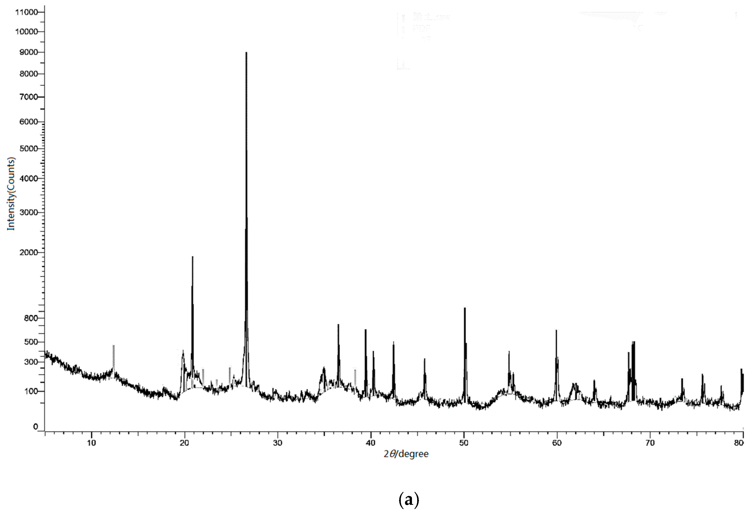
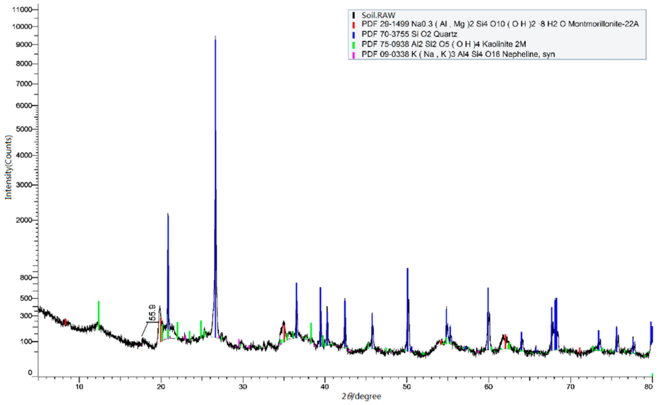
The soil samples need to be wrapped with plastic film to prevent water loss. Following the “Highway Geotechnical Test Regulations”, the basic physical properties were obtained and are listed in Table 1. The soil sample’s liquid limit and the plasticity index were recorded as 67.3% and 33.4, respectively, so this soil can be categorized as high-liquid-limit soil according to the “Chinese Soil System Classification”. The mineral composition of the soil sample was analyzed by an X-ray diffraction test (XRD). As shown in Figure 2, the main mineral components in the roadbed soil include montmorillonite, quartzite, and kaolinite, marked in red, green, and blue. The content of secondary minerals such as highly hydrophilic montmorillonite and kaolin is relatively high.
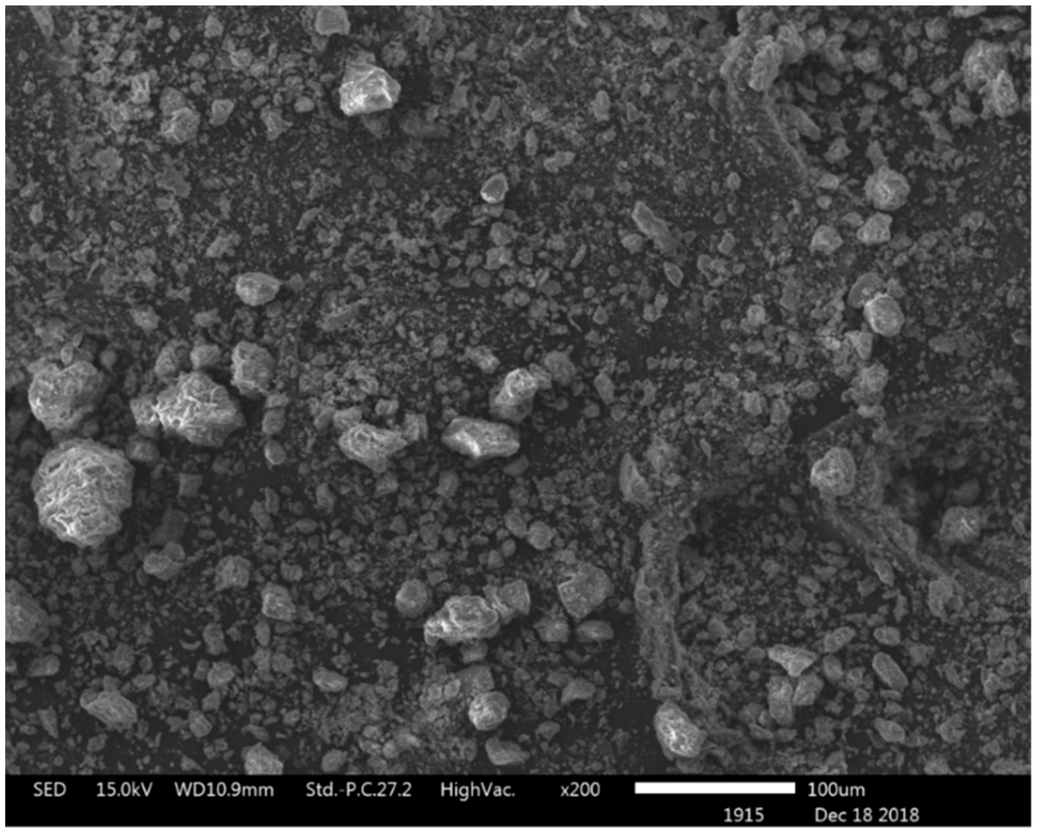
A scanning electron microscope (SEM) was used to observe the microstructure of the sample surface. As shown in Figure 3, the sample surface’s particle structure was loose, and the aggregates were small.

2.1.2. Inorganic Stable Materials

The cement is ordinary Portland cement with a strength grade of 42.5 MPa; quicklime is ordinary quicklime for construction, in which the purity of calcium oxide is greater than 95%. The fly ash is an unpolluted cementing material from a power plant in Huanggang City, Hubei Province, China; its main components are SiO2 and Al2O3, and it is smooth and spherical in the microscopic state.

2.1.3. Anionic Surfactant

The anionic surfactant in the test is sulfonated oil (SO) [32], a kind of amphiphilic surfactant, which is mainly used in leather, textile and papermaking industries. SO is a water-soluble oil, mostly prepared by treating fatty oleic acid with concentrated sulfuric acid (H2SO4) or fuming sulfuric acid (H2SO4·XSO3), where X is defined as the content of sulfur trioxide per mole. The typical sulfonated oil molecule is usually expressed as R-(SO2)OH.
After SO enters the soil, it will induce physical, chemical and lubricating effects on the soil particles [33,34,35]. The molecular structure of SO mainly determines the physical and chemical effects. The SO molecule is composed of a negatively charged hydrophilic or polar head (i.e., (SO2)OH) and a hydrophobic tail (i.e., R, a hydrocarbon). The negatively charged hydrophilic head will absorb the cations on the soil particle surface so that the thickness of the double electric layer around the soil particles and specific surface area of the soil particles is reduced and then works together with the hydrophobic tail to transform the hydrophilicity of the soil particles into hydrophobic or water-repellent particles. The lubrication effect mainly depends on the viscosity of the pore fluid. The increase in SO will make the soil particles more lubricated, reducing the water surface tension and helping particles slide during the compaction process. This sliding may lead to a decrease in strength and stiffness but an increase in soil ductility. In this study, SO was used as an important component of the composite soil stabilizer to improve the high-liquid-limit soil’s water stability. The physical and chemical properties of the SO are listed in Table 2.

2.2. Methods

2.2.1. Test Sample Preparation

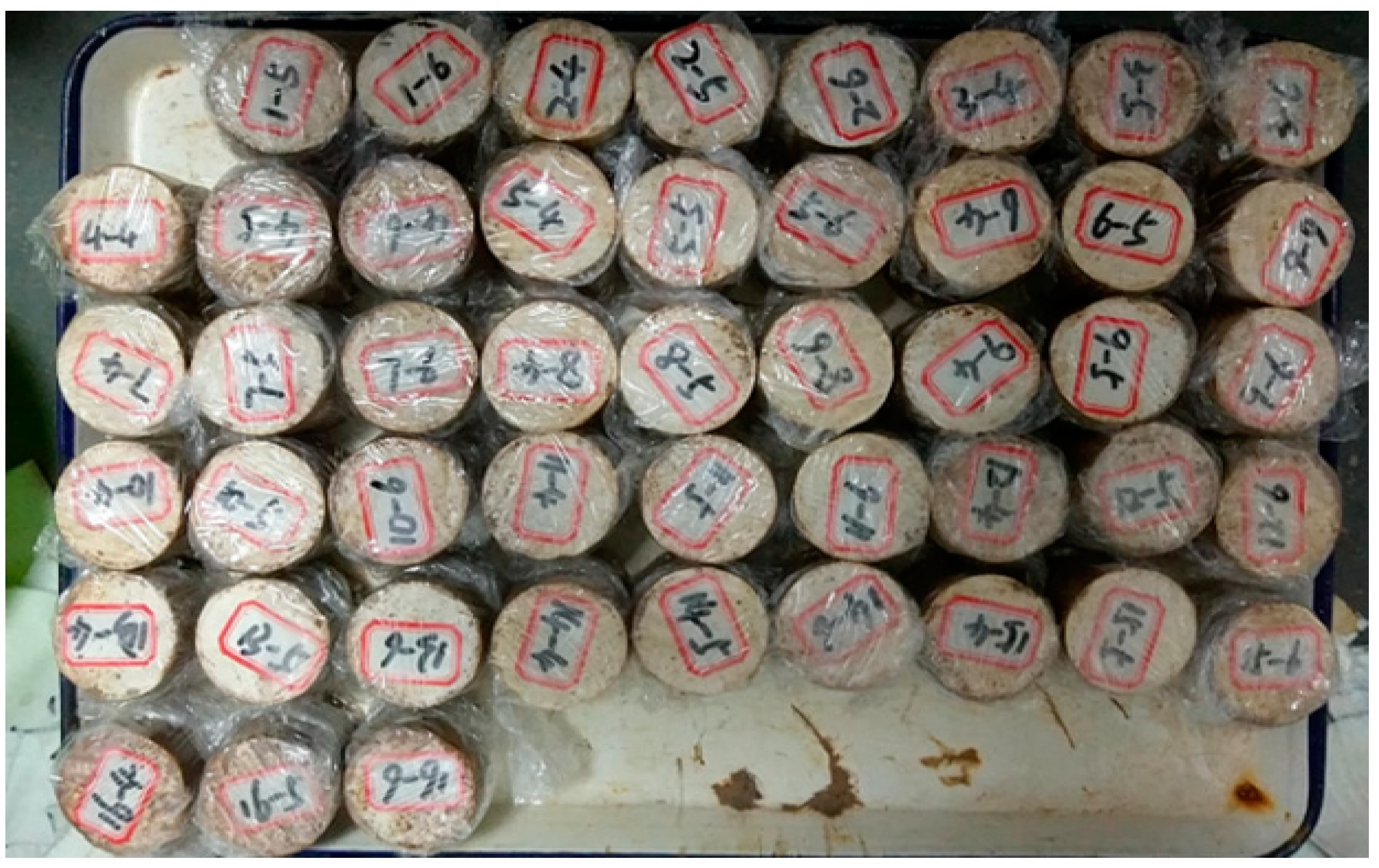
Before preparing the sample, each group of samples’optimal moisture content was determined through compaction tests following the “Highway Geotechnical Test Regulations”. During the sample preparation, the water was added according to each group’s optimal moisture content. In the strength test, the sample is made into a cylindrical shape with a size of φ50 mm × h50 mm. The test pieces are shown in Figure 4.

2.2.2. Test Scheme

  • Single mixing test
In order to explore the individual effect mechanism of the inorganic stable material, etc. the strength and water stability of the stabilized soil, a single-mixing test plan for the inorganic stabilizing material and SO was designed. Referring to the research results of special soil treatment, the single mixing plan for inorganic stable materials adopts 0%, 3% (1% for cement, quicklime, and fly ash), 6% (2% for cement, quicklime, and fly as), 9% (3% for cement, quicklime, and fly ash), 12% (4% for cement, quicklime, and fly ash), 15% (5% for cement, quicklime, and fly ash), while the single mixing plan for SO adopted 0%, 0.05%, 0.10%, 0.15%, 0.20% and 0.25%. The above mixing ratio is the mass ratio of the admixture to the drying soil.
The proportion of SO is relatively small, and it needs to be mixed with water before adding to make it evenly distributed in the soil sample. In this study, the unconfined compressive strength (UCS) test, the flooding strength test and the scanning electron microscope test (SEM) were carried out for the two single-mixing stabilized soils. The X-ray diffraction test (XRD) was carried out for the SO-stabilized soil to identify new mineral components produced during the modification process.
2.
The orthogonal test
To find the optimal ratio of the composite stabilizer, each component’s mixing ratio in the composite stabilizer was determined according to the results of the single mixing test, as listed in Table 3. In order to improve test efficiency, an orthogonal experiment was designed. Unconfined compressive strength (UCS) test and the flooding strength test were carried out for the composite-stabilized soil.

3. Results

3.1. Results of the Single Mixing Tests

3.1.1. Results of the Laboratory Tests

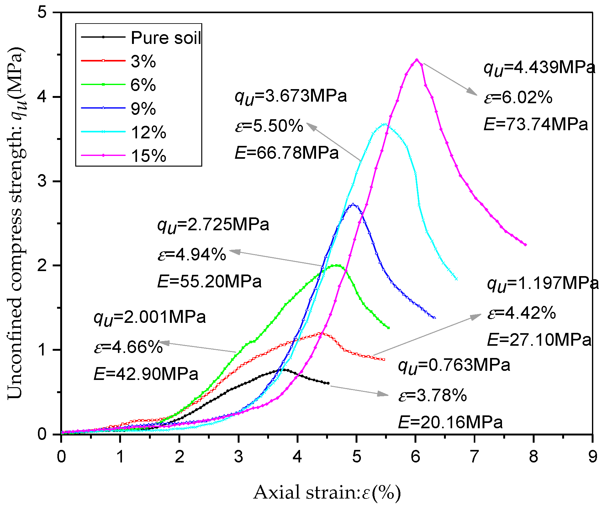
For pure soil and various inorganic stable soils, their stress–strain curves of UCS tests are shown in Figure 5 and Figure 6. It can be seen that when the pure soil’s curing age was 7 days and 28 days, respectively, the unconfined compressive strength qu was 0.696 MPa and 0.763 MPa, and Young’s modulus E was 20.16 MPa and 19.22 MPa.
For the two curing ages, the strength and stiffness were closely related to the content of inorganic material; the greater the inorganic material’s total content, the greater the qu and E of the inorganic stabilized soil was. When the total proportion of the inorganic stable material was 15% (5% cement, 5% quicklime and 5% fly ash), the peak values of qu and E were reached. At the 7th curing day, qu1max = 4.439 MPa, E1max = 73.74 MPa, and at 28th curing day, qu2max = 5.903 MPa, E2max = 89.18 MPa.
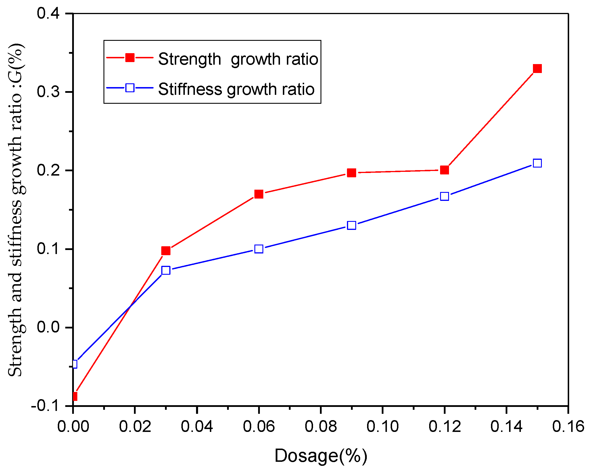
As the curing age increased, the qu and E gradually increased; in the actual construction process, the strength growth ratio from 7 to 28 days is an important guarantee for the project’s continuously stable and efficient progress. Assuming the G represents the growth ratio of the qu and E from the 7th curing day to the 28th curing day, the growth ratio of qu and E can be calculated using Equations (1) and (2). When the proportion of the inorganic material was 15%, Gqumax = 32.98% and GEmax = 20.94%. For other groups, their variations of G are shown in Figure 7.
G q u = q u 2 q u 1 q u 1 × 100 %
where the qu1 is the value of qu on the 7th curing day, and qu2 is the value of qu on the 28th curing day.
G E = E 2 E 1 E 1 × 100 %
where E1 is the value of E on the 7th curing day, and E2 is the value of E on the 28th curing day.
As shown in Figure 7, the pure soil’s Gqu and GE were both less than 0%, and this is because, under the condition of unconfined wet nutrient, the montmorillonite in the soil sample made the soil structure slightly swell after absorbing water, reducing the strength and rigidity. As the addition content increased, the Gqu and GE of the stabilized soil both increased. Under the reasonable curing condition, as the curing time increased, the three kinds of inorganic materials’ strength and stiffness increased, and the growth rate gradually increased and eventually stabilized.
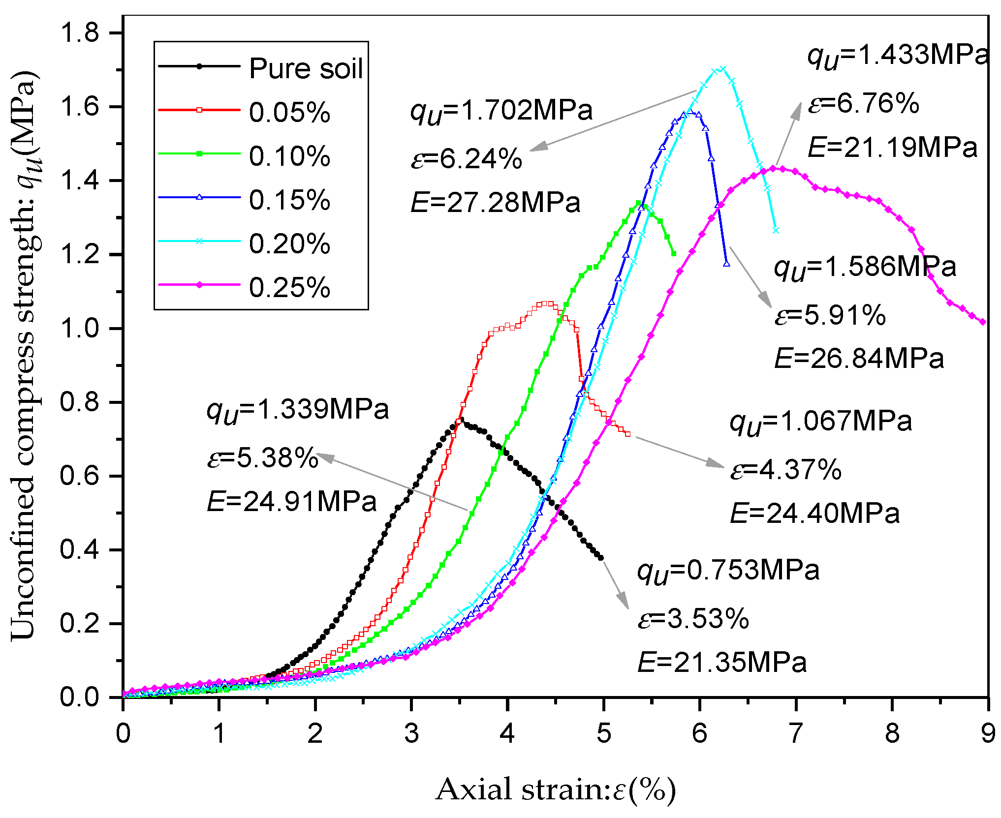
As for the pure soil and various SO-stabilized soils, the stress–strain curves in the UCS test on the 7th and 28th curing days are shown in Figure 8 and Figure 9. It was indicated that when the SO content was less than 0.2%; the SO content presents a strong positive correlation with the strength and stiffness of the stabilized soil. By contrast, when the SO content reached 0.25%, the strength and stiffness of stabilized soil decreased but is still slightly better than that of pure soil; compared with inorganic materials, the strain ε corresponding to the strength peak point of the SO modified sample increased to avoid brittle failure. It was also indicated that, as the SO content increased, this ε also gradually increased.
The peak values of qu and E were the largest when the SO content was 0.2%, qu1max = 1.787 MPa, E1max = 28.37 MPa at the 7th curing day, qu2max = 1.702 MPa, E2max = 21.19 MPa at the 28th curing day. According to the test results, When the SO content was less than 0.2%, as the curing time increased, the strength and stiffness at the 28th day were slightly reduced compared with that at the 7th day for the same set of tests. On the contrary, the strength and stiffness were slightly increased when the SO content was 0.25%.
In order to verify the reliability of this conclusion, the author added a test with 0.3% SO content to prove it. The supporting test shows that when the SO content is 0.3%, the strength is 1.052 MPa, and the elastic modulus is 15.73 MPa. Compared with the solidified soil with the SO content of 0.25%, the strength and stiffness are further reduced. The test proves that the above conclusion is reliable.
When the SO content was less than 0.2%, qu and E increased with the increase in the content, indicating that the primary effect of SO on strengthening the soil structure is the physical and chemical effect. However, when the SO content reached 0.25%, qu and E began to decrease, ε significantly increased, suggesting that the lubrication effect was dominant at this time. It was found that the SO content was in charge of the transition of these two effects. When the SO content was low than 0.2%, the soil particles were not completely covered with SO molecules; combined with the soil particles, the SO molecules played a role in enlarging the soil’s structure. At this time, there was no excess SO molecule in the soil particles’ pore, the physical and chemical effect was greater than the lubricating effect, and the strength and rigidity of the soil were improved.
However, with the increase in the content, the strength and rigidity were increased to the extreme value because the soil particles were gradually covered with SO molecules; as SO continuously increased, the excess SO molecules entered the soil particle pore and the lubrication effect appeared, then the strength and stiffness of the soil gradually decrease, and the ductility was improved. Moreover, in the process of curing, SO is inevitably partly lost due to volatilization or other reasons. When the SO content was less than 0.2%, the loss of SO molecules reduced the sulfonated oil molecules around the soil particles, and the physical and chemical effects decayed and limited the enhancement of the stabilized soil strength and stiffness.
Nevertheless, when the SO content was equal to 0.25%, the SO molecules in the pores of the soil particles were lost first, weakening the lubrication effect, but the SO molecular around the soil particles remained unchanged or even reached an appropriate amount, and the physical and chemical effects were not significantly weakened. Therefore, the strength and stiffness of the stabilized soil did not weaken in the later stage, which also explains the differences in the variation of strength and stiffness of stabilized soils. Considering the loss of SO, it is recommended that when SO is selected as a single stabilizer in the project, a sealing treatment or an appropriate increase in the amount should be used to ensure the effectiveness of SO.
The results of the two single-mixing tests showed that, compared with SO, inorganic materials were more prominent in improving the strength and stiffness of high-liquid-limit soil. However, except for the strength and stiffness as the improvement indicators, water stability is even more essential. Water stability refers to the stability of the strength and stiffness before and after immersion, which is generally represented by the water stability coefficient HS; its calculation is shown in Equation (3).
H S = q u q u × 100 %
where qu’ is the unconfined compressive strength after the sample is immersed for 24 h at the one-day point before the specified curing time; qu is the unconfined compressive strength at the specified curing day.
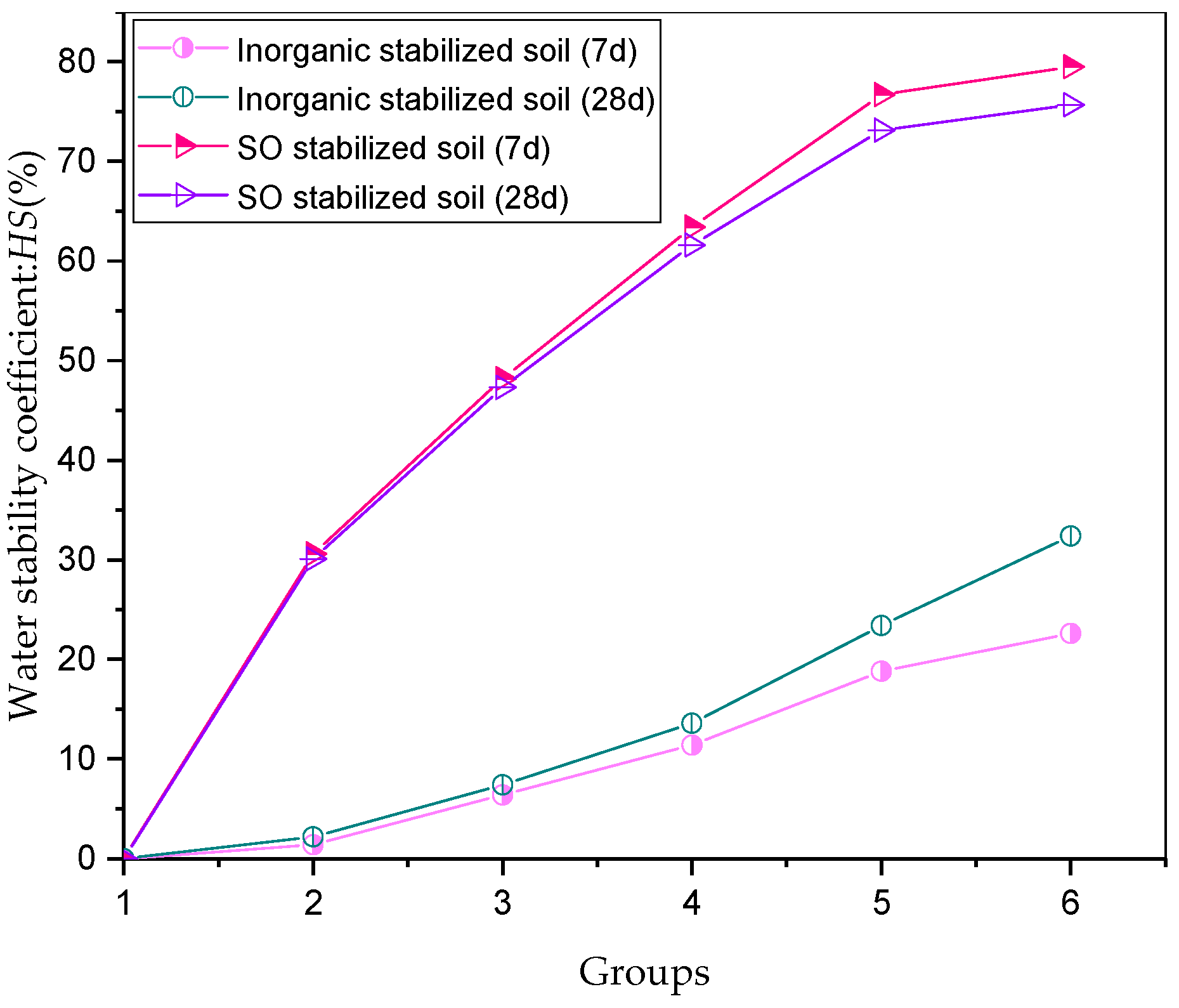
Figure 10 shows the water stability coefficient curves of the pure soil, inorganic stabilized soil, and SO-stabilized soil at 7 d and 28 d. Numbers from one to six represent the six different contents of two stabilizers ranging from 0% to the maximum in the uniaxial unconfined compressive strength test.
It was found that the pure soil sample disintegrated quickly after being immersed, and the HS was 0%. The strength after immersion was considered to be 0MPa because the strength test cannot be carried out. Inorganic materials and SO have a certain effect on improving water stability of the high liquid limit soil. At the 7th curing day, with the increase in inorganic material content, the HS increased from 0% to 33.9%; with the increase in SO content, the HS increased from 0% to 79.5%. At the 28th curing day, the HS of inorganic stabilized soil can reach up to 48.6%, and the HS of SO-stabilized soil can reach up to 75.7%, indicating that SO had a more significant effect on water stability.
As for the single material stabilized soil, no matter the inorganic stabilized soil or SO-stabilized soil, the HS at the 7th day and 28th day is positively correlated with the material content. From the perspective of curing time, from the 7th day and 28th day, the HS of soil increased at the same inorganic stabilizer content, while the HS of SO-stabilized soil decreased.
It was found that, for the inorganic stabilized soil, only when the total addition content was greater than 12% can the specimens maintain their integrity after immersion for 24 h. When the total addition content was less than 12%, the specimens after immersion would disintegrate, or soil particles fall off to some degree.
According to the water stability test results, SO can significantly improve the water stability of high-liquid-limit soil compared to inorganic stabilizer. However, according to the strength test results, SO stabilizer was found to be unable to improve the mechanical properties significantly. The mechanical properties and water stability are two indispensable indicators of high-liquid-limit soil in subgrade filling. Therefore, in order to explore the effect of using the inorganic stabilizer and OS at the same time, this study further conducted an orthogonal experiment on the composite soil stabilizer composed of inorganic stabilizing materials and SO.

3.1.2. Microscopic Analysis of the Mechanism of Mixing Single Stabilizer

In order to reveal the microscopic mechanism of inorganic materials and SO in improving the strength and water stability of high-liquid-limit soil, an XRD test was carried out on three kinds of SO-stabilized soils (0%, 0.1% and 0.2%) on the 7th day, and the corresponding patterns are shown in Figure 11a–c. It can be seen that, compared with the pure soil, there were no new diffraction peaks in the spectra of stabilized soils with 0.1% and 0.2% SO, while the original diffraction peaks were basically unchanged, indicating that the addition of SO did not generate new minerals or destroy the lattice structure of the original minerals in the liquid limit soil.
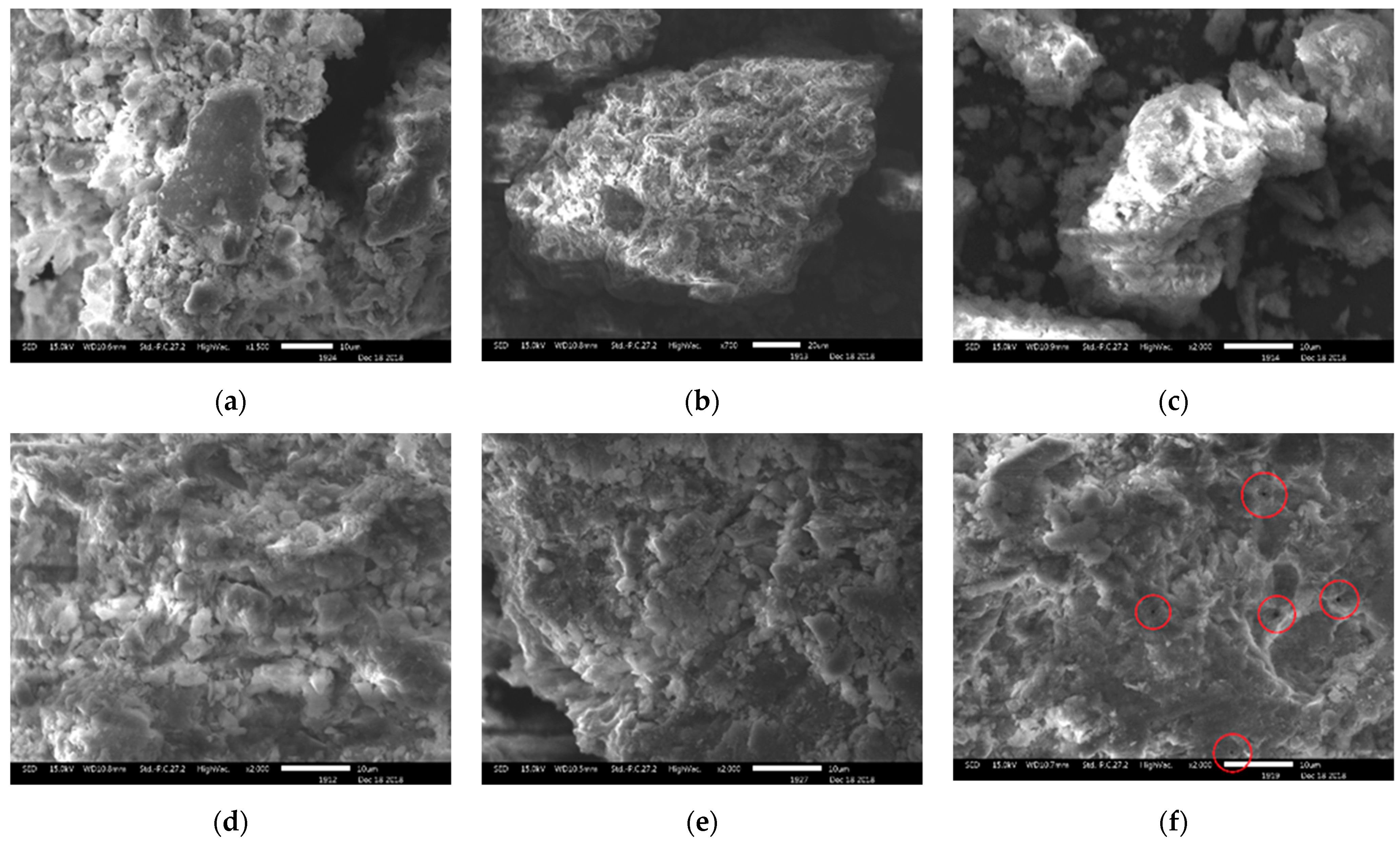
On the 7th day, the soils stabilized by six different percentages of SO (0%, 0.05%, 0.1%, 0.15%, and 0.2% and 0.25%) were further subject to SEM tests; the corresponding SEM photos are shown in Figure 12. It can be seen that the agglomerates in pure soil are small, mostly connected in the form of point-to-surface and edge-to-surface, and the structure is looser and mostly clastic. There was no new crystal structure found in the SO-stabilized soil. As the SO content increased, the aggregates became larger, and the connection form transitioned from point-to-face and edge-to-face to face-to-face, the structure became more encrypted. When the content was 0.15%, the structure reached a condensed state. The stabilized soil with 0.25% SO had the densest structure, but with a small amount of dark spot-like areas in the soil. The SEM photos of SO-stabilized soil can explain its improvement in strength and stiffness to a certain extent. Combining with the previous macroscopic experiments, the small amount of dark spot-like areas in 0.25% SO-stabilized soil is assumed to be caused by the aggregation of excessive SO molecules. The SO liquid is reddish-brown but became black after vacuum drying.
At the 7th curing day, SEM tests were conducted on the stabilized soils with six percentages of inorganic stabilizer (0%, 3%, 6%, 9%, 12%, and 15%); the corresponding SEM photos of the inorganic stabilized soil are shown in Figure 13.
According to Figure 13, it can be seen that, compared to pure soil and SO-stabilized soil, fibrous CSH gel crystals and flake-shaped calcium hydroxide crystals were generated in each group of inorganic stabilized soils. The number of crystals and the structural complexity were positively correlated with the inorganic content. When the inorganic content was less than 6%, fibrous CSH gel and a very small amount of calcium hydroxide crystals appeared locally with a relatively concentrated distribution, and there was no effective connection between them. When the content was greater than 9%, the two crystals gradually increased and interlaced with each other; thus, an integral frame structure was formed to enhance the soil structure’s support and cohesion.

3.2. Results of the Orthogonal Mixing Tests

3.2.1. Results of the Laboratory Tests

Following the orthogonal test scheme, 16 groups of samples were subjected to UCS tests on the 7th and 28th curing days; the obtained unconfined compressive strengths are shown in Figure 14. Compared with pure soil, the strength of composite-stabilized soil was improved. For the same sample group, the 28 d strength was higher than the 7 d strength, the maximum strength of 7 d was 4.63 MPa, and the maximum strength of 28 d was 8.21 MPa. If the 7 d strength is used as the effective strength index of the subgrade filling soil, it is required to reach at least 4MPa, and there are 8 qualified groups, including the groups 2, 3, 6, 9, 11 and 13–15.
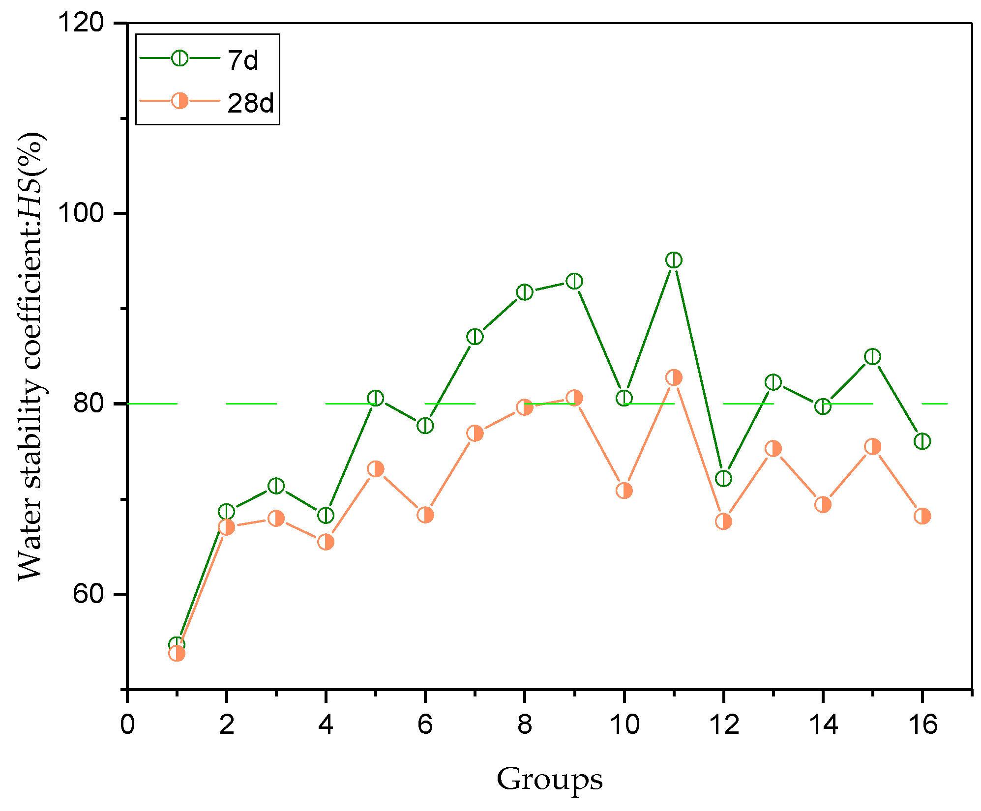
Water stability coefficient curves of 16 groups of 7 d and 28 d composite-stabilized soils are shown in Figure 15. It was found that, after being immersed in water for 24 h, the 16 groups of specimens did not fall off or disintegrate. Compared with pure soil and the single-mixing stabilized soil, the water stability coefficient of composite-stabilized soil with the same adding proportion increased. The maximum 7d water stability coefficient was 95.10%, and the maximum 28 d water stability coefficient was 82.76%. The roadbed filling design required the 7 d water stability coefficient to be greater than 80%. In the composite-stabilized soil, there are 8 qualified groups, including the groups 5, 7–11, 13 and 15. In the same group of experiments, the 7 d water stability was greater than that of 28 d, which was consistent with SO-stabilized soil results. Among the 16 experiments, 3 qualified groups meet the requirements of strength and water stability at the same time, namely groups 9, 11 and 15. Therefore, these three groups can be used as the reference mix ratio of the high liquid limit soil composite soil stabilizer in the lake areas.

3.2.2. Analysis of the Orthogonal Test Variance

In order to more intuitively reflect the effect of each adulterating agent on strength and water stability, the main effects of the strength and water stability coefficient of the composite-stabilized soil were analyzed. Among them, the main effect analysis results of 7 d and 28 d strength of composite-stabilized soil are shown in Table 4 and Table 5.
According to Table 4, the significant coefficients P of cement, quicklime, SO, and fly ash for the 7 d strength of composite-stabilized soil were: 0.011, 0.038, 0.0604, and 0.113, respectively, and the P of cement and quicklime were both less than the critical value of 0.05. According to significance test criteria, cement and quicklime are considered to affect the 7 d strength significantly, while the P of SO and fly ash was greater than 0.05, indicating their insignificant effect.
Similarly, as listed in Table 5, when the dependent variable is 28 d strength, the P of cement, quicklime and fly ash were all less than the critical value of 0.05; they are considered to affect the 28 d strength significantly. It can be concluded that the inorganic stabilizer provides most of the strength, which is consistent with the results of the single-mixing test.
Table 6 and Table 7 shows the main effect analysis results of the 7 d and 28 d water stability coefficient of composite-stabilized soil. It can be seen that the P values of SO were 0.001 and 0.004, respectively, which were both less than the critical value of 0.005; SO is considered to have a significant effect on the 7 d and 28 d water stability of the composite-stabilized soil. The P of other admixtures were all greater than the critical value of 0.005, and the effect is considered not significant. Therefore, the main indicator affecting the composite-stabilized soil’s water stability is the SO content, which is consistent with the single mixing test results.
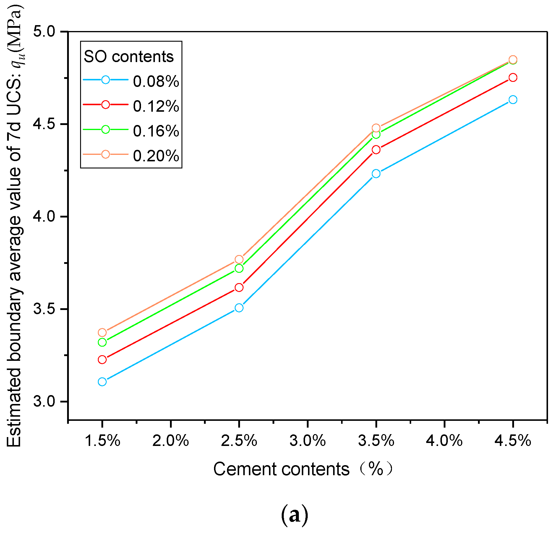
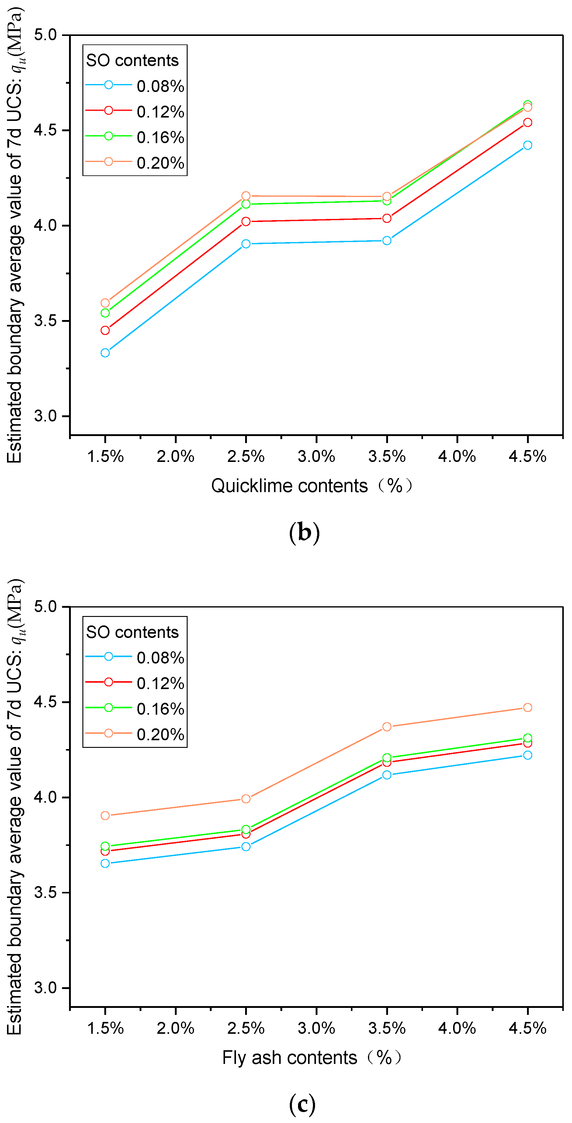
The effect of the interaction between SO and inorganic stabilizer on the strength of composite-stabilized soil was explored. As for the 7 d strength, the interaction between SO and cement is shown in Figure 16a. When the SO content was 0.08% and 0.12%, curves were roughly parallel, indicating that SO and cement’s interaction effect was not significant. When the SO content was 0.16% and 0.2%, and the cement content was greater than 3.5%, the two curves were close to each other, suggesting an interference interaction effect between SO and cement. According to Figure 16b, when the SO content was greater than 0.16% and the quicklime content was greater than 2.5%, the two curves were close and finally intersected each other, indicating an interference interaction effect between a large amount of SO and the quicklime in the early stage of hydration. The curves in Figure 16c were always parallel, indicating no interaction effect between SO and fly ash in the early stage of hydration.
After entering the soil, the binding of SO molecules with the soil particles changed the soil particles’ hydrophilicity. Similarly, when SO molecules encountered cement, quicklime and fly ash, they would also spontaneously combine with them, showing certain hydrophobicity. Before the 7th curing day, cement and quicklime were at the hydration peak and needed much water. The combination of SO molecules affected cement’s hydration rate, showing a further interference interaction effect. The hydration rate of fly ash was slow, and the hydration cycle was long, and less water was required in the early hydration process, so the SO molecules did not have a significant impact on the hydration of fly ash.
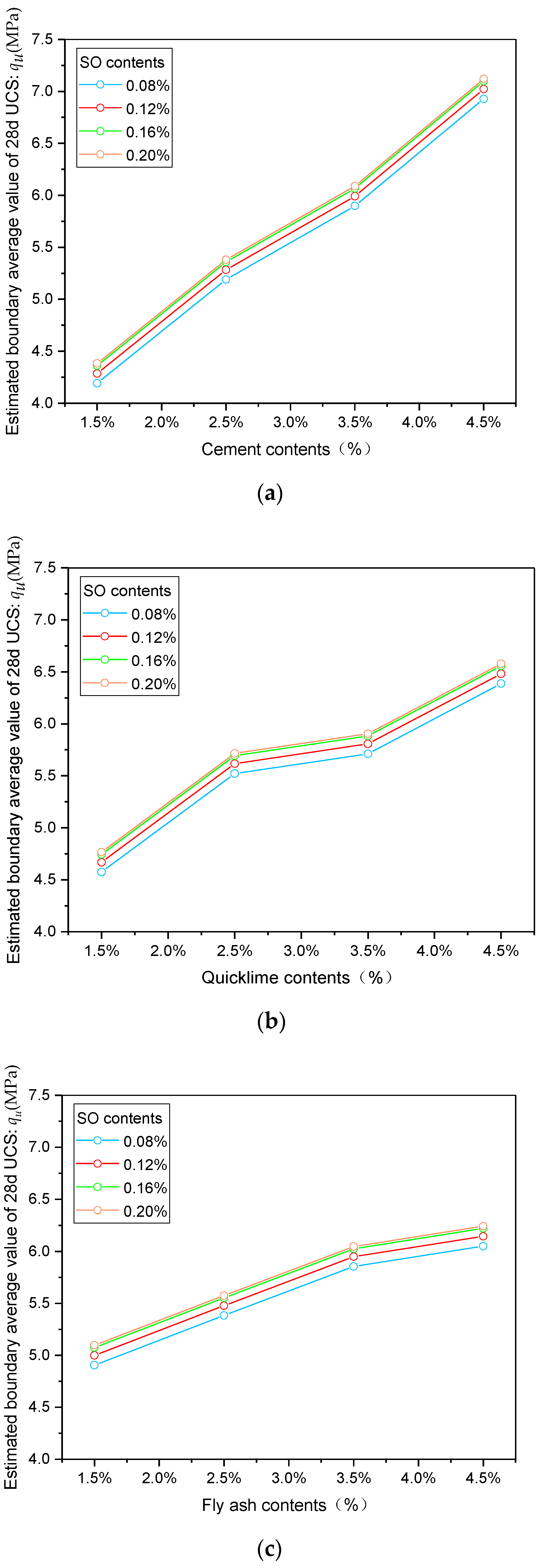
As for the 28 d strength, the interaction between SO and every inorganic material is shown in Figure 17. The roughly parallel contour curves indicated no significant interaction effect between SO and inorganic materials in the middle and later hydration process. With the partial loss of SO molecules and the increase in the curing time, the inorganic material obtained sufficient water, and the hydration proceeded normally. There was no significant interaction effect between SO and inorganic materials on the 28th curing day.

3.2.3. The Cost Analysis

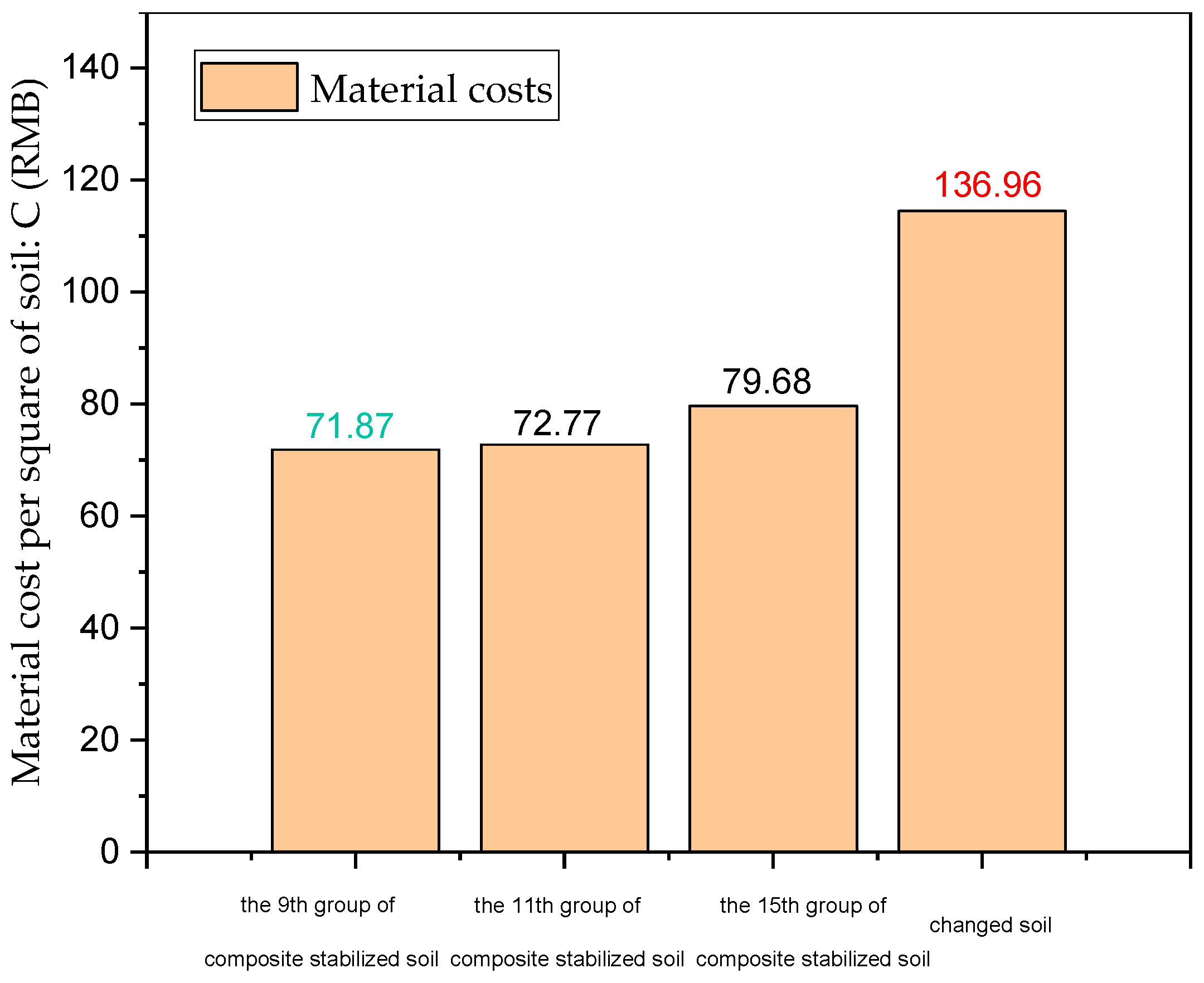
The soil replacement scheme and the three groups of composite stabilizers were compared to carry out the cost analysis. The composite-stabilized soil only considered the material cost per unit volume, and the replacement treatment only considered the disposal of the remaining soil and the expenses for purchased soil. The market prices of modification materials are cement 525 RMB/t, quicklime 340 RMB/t, fly ash 210 RMB/t, and SO 3000 RMB/t. The remaining soil is 38.31 RMB/m3, and the purchased soil is 76.09 RMB/m3. The material cost per m3 in each scheme is shown in Figure 18. The material cost of composite-stabilized soil is lower than that of filling soil. Considering economic benefits, the 9th group of composite soil stabilizers is finally selected, namely cement 4.5%, quicklime 1.5%, fly ash 2.5%, and sulfonated oil 0.2%.

4. Discussion

The advantages of composite-stabilized soil: high strength, high rigidity, no disintegration in contact with water, good water stability.
Disadvantages of composite solidified soil: the construction process is more complicated, the maintenance conditions are more demanding, the engineering volume is increased, and the filling cost is increased.
Adaptation conditions of the composite soil solidification agent: suitable for high liquid limit soil subgrade filling projects in areas where the temperature is higher than −10 °C, rainfall is abundant, and the lake is densely covered. It is not suitable for areas where the temperature is lower than −10 °C, because the melting point of sulfonated oil is −10 °C. When the melting point is lower than the melting point, the sulfonated oil solidifies and cannot exert its effect. It is not applicable to soils other than high-liquid-limit soils.
Contributions of this paper: providing an effective soil stabilizer for the high liquid limit soil in the Dongting Lake area; rationally using the bad soil quality, making contributions to saving land resources, protecting the environment and sustainable construction, and also for other special related research on soil providing research ideas.
Limitations of this article:
  • The research in this article is only aimed at the high-liquid-limit soil in the Dongting Lake region of China, and does not involve the high-liquid-limit soil in other regions, and has certain limitations;
  • This article does not explore the construction technology of the improved high-liquid-limit soil subgrade in detail.
Future research directions:
  • Research on the solidification mechanism of improved high liquid limit soil under freeze–thaw cycles and dry–wet cycles;
  • Use numerical simulation to explore the curing mechanism quantitatively;
  • Development of field testing and research of construction technology;
  • Explore the wider application range of the composite soil solidification agent;
  • Using artificial neural networks to develop a model which would give a UCS or E modulus with an inorganic stabilizer and surfactants as an input.

5. Conclusions

By studying the improvement mechanism of several commonly used inorganic materials and sulfonated oil on high liquid limit soil, the following conclusions can be finally obtained:
  • There is a significant positive correlation between the content of inorganic materials and the qu and E of stabilized soil. When the SO content was less than 0.2%, the qu and E of SO-stabilized soil increased with its content. When the SO content reached 0.25%, this positive correlation became negative; the inorganic materials more significantly affected the strength of high liquid limit soil.
  • Inorganic stabilizers can improve the water stability of high liquid limit soil to a certain extent. The water stability coefficient of inorganic-stabilized soil reached up to 33.9% on the 7th curing day and 48.6% on the 28th curing day; SO-stabilized soil can more apparently improve the water stability of high liquid limit soil; the water stability coefficient reached up to 79.5% on the 7th curing day and 75.7% on the 28th curing day.
  • The XRD pattern shows that no new minerals were produced in the SO-stabilized soil, and the original mineral lattice structure was not destroyed; SEM photos show that, as the SO content increased, the aggregates in the soil increased, and the contact form transited from point-to-face and edge-to-face to face-to-face, making a denser structure. The CSH gel and calcium hydroxide crystals generated in the inorganic stabilized soil filled the soil pores, making the soil more compact, and the cross-arranged crystals gradually became the binder between the soil framework and the soil particles, improving the strength and stiffness.
  • Composite-stabilized soil can simultaneously improve the strength and water stability of high liquid limit soil. Through analysis of strength, water stability and cost, it was determined that the compound stabilizer ratio for the high liquid limit soil in the lake area was: cement 4.5%, quicklime 1.5%, fly ash 2.5%, and SO 0.2%.
  • The main effect analysis shows that cement and quicklime have a significant effect on the 7 d strength of stabilized soil, and the three inorganic materials have significant effects on the 28 d strength, indicating that the composite-stabilized soil is mainly improved by inorganic stabilized materials. In terms of water stability, SO has a significant effect on the 7 d and 28 d water stability of stabilized soil, indicating that the composite-stabilized soil’s water stability is improved mainly by SO.
  • The interaction effect analysis shows that as for the 7 d strength when the SO content is greater than 0.16% and the cement content is greater than 3.5%, there is an interference type interaction effect between these two. When the SO content is greater than 0.16% and the quicklime content is greater than 2.5%, interference-type interaction effects appears between SO and quicklime, which vanished at the 28th curing day.

6. Patents

Chinese invention patent:
  • You Wang, Hongdong Zhang, Zhuangzhuang Zhang, Mingming Tang. A soil curing agent for high liquid limit soil roadbed.

Author Contributions

Conceptualization, Y.W. and H.Z.; methodology, H.Z. and Z.Z.; software, H.Z.; validation, Y.W., H.Z. and Z.Z.; formal analysis, H.Z.; investigation, Z.Z.; resources, Y.W.; data curation, H.Z.; writing—original draft preparation, H.Z.; writing—review and editing, Y.W., H.Z. and Z.Z.; visualization, Y.W.; supervision, Y.W.; project administration, Y.W. and H.Z.; funding acquisition, Y.W. All authors have read and agreed to the published version of the manuscript.

Funding

This research was funded by the National Science Foundation of China (NSFC), grant number 51778633, the Key R&D Project of Hunan Provincial Department of Science and Technology, grant number 2017SK2213.

Data Availability Statement

The data presented in this study are available on request from the corresponding author.

Acknowledgments

The authors are very grateful to Central South University (CSU) for providing the test site and materials, and Hunan Pingyi Expressway Group for providing the test soil and geological data.

Conflicts of Interest

The authors declare no conflict of interest.

References

  1. Lu, Z.; Fang, R.; Zhan, Y.; Yao, H. Study on the dynamic deformation of road high liquid limit subgrade soil. Adv. Civ. Eng. 2019, 2019, 4084983. [Google Scholar] [CrossRef]
  2. Que, Y.; Lin, Y.Q.; Gong, F.Z. Experimental Study on the Performance of Compound Improved HLLS (High Liquid Limit Soil) with Various Curing Agents. Key Eng. Mater. 2017, 753, 300–304. [Google Scholar] [CrossRef]
  3. Zhang, J.; Fan, H.; Zhang, S.; Liu, J.; Peng, J. Back-Calculation of Elastic Modulus of High Liquid Limit Clay Subgrades Based on Viscoelastic Theory and Multipopulation Genetic Algorithm. Int. J. Geomech. 2020, 20, 04020194. [Google Scholar] [CrossRef]
  4. Wang, J.; Wu, L.; Feng, R. An experimental case study of a high-liquid-limit lateritic soil with its application in road construction. Road Mater. Pavement Des. 2016, 18, 1423–1433. [Google Scholar] [CrossRef]
  5. Lei, Z. Experimental Study on Road Properties of High Liquid Limit Soil in Yunfu Highway. Open Constr. Build. Technol. J. 2015, 9, 46–51. [Google Scholar] [CrossRef] [Green Version]
  6. Liu, X.; Sheng, K.; Hua, J.H.; Hong, B.N.; Zhu, J.J. Utilization of high liquid limit soil as subgrade materials with pack-and-cover method in road embankment construction. Int. J. Civ. Eng. 2015, 13, 167–174. [Google Scholar]
  7. Zhang, W.-H.; Zheng, H.-W.; Qi, J.-W.; Wang, B.-T. Experimental Study on the Feasibility of Using Water Glass and Aluminum Sulfate to Treat Complications in High Liquid Limit Soil Subgrade. Adv. Mater. Sci. Eng. 2015, 2015, 457978. [Google Scholar] [CrossRef] [Green Version]
  8. Bandara, N.; Hettiarachchi, H.; Jensen, E.; Binoy, T. Upcycling Potential of Industrial Waste in Soil Stabilization: Use of Kiln Dust and Fly Ash to Improve Weak Pavement Subgrades Encountered in Michigan, USA. Sustainability 2020, 12, 7226. [Google Scholar] [CrossRef]
  9. Yang, J.; Sun, C.; Tao, W.; Gao, J.; Huang, B.; Zhang, J. Laboratory Investigation of Compaction Characteristics of Plant Recycled Hot-Mix Asphalt Mixture. Sustainability 2021, 13, 3005. [Google Scholar] [CrossRef]
  10. Zheng, Q.; Mauro, J.C.; Ellison, A.J.; Potuzak, M.; Yue, Y. Universality of the high-temperature viscosity limit of silicate liquids. Phys. Rev. B 2011, 83, 212202. [Google Scholar] [CrossRef]
  11. Zhao, Y.; Gao, Y.; Zhang, Y.; Jia, Y. Effect of fines on the drying crack resistance of composite soil stabiliser-stabilised gravel soil. Road Mater. Pavement Des. 2019, 20, 1255–1274. [Google Scholar] [CrossRef]
  12. Lu, X.; Cui, M.; Wang, P.; Li, B. Application in Cement Soil of Stabilizer in Silt Soft Soil of Wuxi in China. J. Coast. Res. 2018, 83 (Suppl. 1), 316–323. [Google Scholar] [CrossRef]
  13. Ogila, W.A.M. Effectiveness of fresh cement kiln dust as a soil stabilizer and stabilization mechanism of high swelling clays. Environ. Earth Sci. 2021, 80, 1–24. [Google Scholar] [CrossRef]
  14. Mavroulidou, M. Use of waste paper sludge ash as a calcium-based stabiliser for clay soils. Waste Manag. Res. 2018, 36, 1066–1072. [Google Scholar] [CrossRef] [PubMed]
  15. Latifi, N.; Rashid, A.S.A.; Siddiqua, S.; Horpibulsuk, S. Micro-structural analysis of strength development in low- and high swelling clays stabilized with magnesium chloride solution—A green soil stabilizer. Appl. Clay Sci. 2015, 118, 195–206. [Google Scholar] [CrossRef]
  16. Tao, J.Q.; Lin, W.Y.; Luo, X.H.; Qiu, X.; Wu, J.H. Compressive Strength Analysis of Ionic Soil Stabilizer Improving Soil. Key Eng. Mater. 2015, 667, 341–346. [Google Scholar] [CrossRef]
  17. Gautam, S.; Hoyos, L.R.; He, S.; Prabakar, S.; Yu, X. Chemical Treatment of a Highly Expansive Clay Using a Liquid Ionic Soil Stabilizer. Geotech. Geol. Eng. 2020, 38, 4981–4993. [Google Scholar] [CrossRef]
  18. Wang, Y.J.; Lin, W.Y.; Huang, Y.S.; Qiu, X.; Wu, J.H. Analysis of Durability Performance of Ionic Soil Stabilizer Improving Soil. Key Eng. Mater. 2015, 667, 335–340. [Google Scholar] [CrossRef]
  19. Zhang, Z.; Zhang, H.; Zhang, J.; Chai, M. Effectiveness of Ionic Polymer Soil Stabilizers on Warm Frozen Soil. KSCE J. Civ. Eng. 2019, 23, 2867–2876. [Google Scholar] [CrossRef]
  20. Latifi, P.N.; Horpibulsuk, P.S.; Meehan, P.C.L.; Majid, P.M.Z.A.; Tahir, P.M.M.; Mohamad, P.E.T. Improvement of Problematic Soils with Biopolymer—An Environmentally Friendly Soil Stabilizer. J. Mater. Civ. Eng. 2017, 29, 4016204. [Google Scholar] [CrossRef]
  21. Zhang, M.; Guo, H.; El-Korchi, T.; Zhang, G.; Tao, M. Experimental feasibility study of geopolymer as the next-generation soil stabilizer. Constr. Build. Mater. 2013, 47, 1468–1478. [Google Scholar] [CrossRef]
  22. Liu, J.; Chen, Z.; Kanungo, D.P.; Song, Z.; Bai, Y.; Wang, Y.; Li, D.; Qian, W. Topsoil reinforcement of sandy slope for preventing erosion using water-based polyurethane soil stabilizer. Eng. Geol. 2019, 252, 125–135. [Google Scholar] [CrossRef]
  23. Liu, J.; Shi, B.; Jiang, H.; Huang, H.; Wang, G.; Kamai, T. Research on the stabilization treatment of clay slope topsoil by organic polymer soil stabilizer. Eng. Geol. 2011, 117, 114–120. [Google Scholar] [CrossRef]
  24. Chandler, N.; Palson, J.; Burns, T. Capillary rise experiment to assess effectiveness of an enzyme soil stabilizer. Can. Geotech. J. 2017, 54, 1509–1517. [Google Scholar] [CrossRef] [Green Version]
  25. Hosseinpour, Z.; Najafpour-Darzi, G.; Latifi, N.; Morowvat, M.; Manahiloh, K.N. Synthesis of a biopolymer via a novel strain of Pantoea as a soil stabilizer. Transp. Geotech. 2021, 26, 100425. [Google Scholar] [CrossRef]
  26. Pu, S.; Hou, Y.; Ma, J.; Zou, Y.; Xu, L.; Shi, Q.; Qian, S.; Pei, X. Stabilization Behavior and Performance of Loess Using a Novel Biomass-based Polymeric Soil Stabilizer. Environ. Eng. Geosci. 2019, 25, 103–114. [Google Scholar] [CrossRef]
  27. Keykha, H.A.; Mohamadzadeh, H.; Asadi, A.; Kawasaki, S. Ammonium-Free Carbonate-Producing Bacteria as an Ecofriendly Soil Biostabilizer. Geotech. Test. J. 2018, 42, 19–29. [Google Scholar] [CrossRef]
  28. Petry, T.M.; Das, B. Evaluation of Chemical Modifiers and Stabilizers for Chemically Active Soils—Clays. Transp. Res. Rec. 2001, 1757, 43–49. [Google Scholar] [CrossRef]
  29. Katz, L.E.; Rauch, A.F.; Liljestrand, H.M.; Harmon, J.S.; Shaw, K.S.; Albers, H. Mechanisms of Soil Stabilization with Liquid Ionic Stabilizer. Transp. Res. Rec. J. Transp. Res. Board 2001, 1757, 50–57. [Google Scholar] [CrossRef] [Green Version]
  30. Han, S.; Li, H.; Xiang, J. Improvement scheme of high liquid limit soil in Guang-Wu Expressway based on cluster analysis theory. J. Subgrade Eng. 2012, 1, 11–14. [Google Scholar]
  31. Li, P.; Yang, W.; Deng, Y.; Zhang, D. Development status and trend of soil stabilizer. J. Subgrade Eng. 2014, 3, 1–8. [Google Scholar]
  32. Konwar, L.J.; Das, R.; Thakur, A.J.; Salminen, E.; Mäki-Arvela, P.; Kumar, N.; Mikkola, J.-P.; Deka, D. Biodiesel production from acid oils using sulfonated carbon catalyst derived from oil-cake waste. J. Mol. Catal. A Chem. 2014, 388–389, 167–176. [Google Scholar] [CrossRef]
  33. Soltani, A.; Deng, A.; Taheri, A.; Mirzababaei, M. A sulphonated oil for stabilisation of expansive soils. Int. J. Pavement Eng. 2019, 20, 1285–1298. [Google Scholar] [CrossRef]
  34. Onyejekwe, S.; Ghataora, G.S. Soil stabilization using proprietary liquid chemical stabilizers: Sulphonated oil and a polymer. Bull. Eng. Geol. Environ. 2015, 74, 651–665. [Google Scholar] [CrossRef]
  35. Negm, N.A.; Sayed, G.H.; Yehia, F.Z.; Habib, O.I.; Mohamed, E.A. Biodiesel production from one-step heterogeneous catalyzed process of Castor oil and Jatropha oil using novel sulphonated phenyl silane montmorillonite catalyst. J. Mol. Liq. 2017, 234, 157–163. [Google Scholar] [CrossRef]
Figure 1. The soil sampling site.
Sustainability 13 05681 g001
Figure 2. XRD diffraction pattern of undisturbed soil.
Sustainability 13 05681 g002
Figure 3. XRD diffraction pattern of undisturbed soil.
Sustainability 13 05681 g003
Figure 4. Prepared test pieces.
Sustainability 13 05681 g004
Figure 5. Stress–strain curve of inorganic stabilized soil at the 7th curing day.
Sustainability 13 05681 g005
Figure 6. Stress–strain curve of inorganic stabilized soil at the 28th curing day.
Sustainability 13 05681 g006
Figure 7. Strength and stiffness growth ratio of inorganic stabilized soil.
Sustainability 13 05681 g007
Figure 8. Stress–strain curve of SO-stabilized soil at the 7th curing day.
Sustainability 13 05681 g008
Figure 9. Stress–strain curve of SO-stabilized soil at the 28th curing day.
Sustainability 13 05681 g009
Figure 10. Water stability coefficient curves of two kinds of stabilized soils.
Sustainability 13 05681 g010
Figure 11. XRD patterns of three grups of SO-stabilized soils. (a) Pure soil. (b) 0.1% SO. (c) 0.2% SO.
Sustainability 13 05681 g011aSustainability 13 05681 g011b
Figure 12. XRD patterns of three groups of SO-stabilized soils. (a) Pure soil. (b) 0.05% SO. (c) 0.1% SO. (d) 0.15% SO. (e) 0.2% SO. (f) 0.25% SO.
Sustainability 13 05681 g012
Figure 13. XRD patterns of three groups of SO-stabilized soils. (a) Pure soil. (b) 3% inorganic stabilizer. (c) 6% inorganic stabilizer. (d) 9% inorganic stabilizer. (e) 12% inorganic stabilizer. (f) 15% inorganic stabilizer.
Sustainability 13 05681 g013aSustainability 13 05681 g013b
Figure 14. Strength of each group of composite-stabilized soil.
Sustainability 13 05681 g014
Figure 15. Water stability coefficient of each group of composite-stabilized soil.
Sustainability 13 05681 g015
Figure 16. The interaction diagram of SO and inorganic stable materials at 7 days. (a) SO and cement. (b) SO and quicklime. (c) SO and fly ash.
Sustainability 13 05681 g016aSustainability 13 05681 g016b
Figure 17. The interaction diagram of SO and inorganic materials on the 28th day. (a) SO and cement (b) SO and quicklime. (c) SO and fly ash.
Sustainability 13 05681 g017
Figure 18. Comparison of material costs of four high liquid limit soil disposal options.
Sustainability 13 05681 g018
Table 1. Properties of the soil.
Weight Density γ (kN/m)Water Content ω (%)Liquid Limit ωL (%)Plastic Limit ωp (%)Plasticity Index Ip
17.932.367.333.933.4
Table 2. Properties of the soil.
PropertiesValue/Description
specific gravity GS1.04
molecular weight, M (gr/mol)380
physical statehighly viscous liquid
appearancereddish brown
odorslightly pungent
solubility in water (at 20 °C)100%
flammabilitynon-flammable
vapor pressure (mmHg)20
freezing point (°C)−10
boiling point (°C)110
acidity, pH3.1
chemical formulationR-(SO2)OH
Table 3. Orthogonal test table.
GroupCementQuicklimeSoFly Ash
11.5%1.5%0.08%1.5%
23.5%3.5%0.08%3.5%
34.5%4.5%0.08%4.5%
42.5%2.5%0.08%2.5%
52.5%4.5%0.16%1.5%
64.5%3.5%0.12%1.5%
73.5%2.5%0.20%1.5%
81.5%4.5%0.20%3.5%
94.5%1.5%0.20%2.5%
101.5%3.5%0.16%2.5%
112.5%2.5%0.20%4.5%
122.5%1.5%0.12%3.5%
133.5%1.5%0.16%4.5%
143.5%4.5%0.12%2.5%
154.5%2.5%0.16%3.5%
161.5%2.5%0.12%4.5%
Table 4. Main effect test of 7 d strength of composite-stabilized soil.
SourceSSDFMSFP
Model8.198 120.68310.9560.037
Intercept260.9511260.954185.120.023
Cement5.00731.66926.7690.011
Quicklime2.14330.71411.4570.038
SO0.13430.0450.7180.604
Fly ash0.91330.3044.8800.113
Error0.18730.062
Total269.33616
Total after correction8.38515
R = 0.888.
Table 5. Main effect test of 28 d strength of composite-stabilized soil.
SourceSSDFMSFP
Model26.852 122.23860.0790.003
Intercept541.4941541.49414,538.790.047
Cement15.91435.305142.4320.021
Quicklime6.72132.24060.1480.011
SO1.06730.3569.5481.768
Fly ash3.15031.05028.1880.044
Error0.11230.037
Total568.45716
Total after correction26.96315
R = 0.979.
Table 6. Main effect test of 7 d water stability coefficient of composite-stabilized soil.
SourceSSDFMSFP
Model0.165 120.01435.4730.027
Intercept9.98419.98425,813.91.058
Cement0.00730.0026.2270.687
Quicklime0.00730.0026.2060.904
SO0.14130.047121.6220.031
Fly ash0.00930.0037.8380.362
Error0.10130.025
Total10.14916
Total after correction0.16615
R = 0.965.
Table 7. Main effect test of 28 d water stability coefficient of composite-stabilized soil.
SourceSSDFMSFP
Model0.075 120.00617.2020.019
Intercept8.16118.16122,465.260.996
Cement0.00630.0025.4800.498
Quicklime0.00330.0012.3070.255
SO0.06030.02054.7750.024
Fly ash0.00730.0026.2450.583
Error0.30730.041
Total8.23816
Total after correction0.07615
R = 0.928.
Publisher’s Note: MDPI stays neutral with regard to jurisdictional claims in published maps and institutional affiliations.