Article

Research on Vehicle-Road Co-Location Method Oriented to Network Slicing Service and Traffic Video

School of Information and Communication Engineering, Beijing University of Posts and Telecommunications, Beijing 100876, China
*
Author to whom correspondence should be addressed.
Sustainability 2021, 13(10), 5334; https://doi.org/10.3390/su13105334
Submission received: 27 March 2021 / Revised: 25 April 2021 / Accepted: 29 April 2021 / Published: 11 May 2021

Abstract

:
The development of 5G network slicing technology, combined with the application scenarios of vehicle–road collaborative positioning, provides end-to-end, large-bandwidth, low-latency, and highly reliable flexible customized services for Internet of Vehicle (IoV) services in different business scenarios. Starting from the needs of the network in the business scenario oriented to co-location, we researched the application of 5G network slicing technology in the vehicle–road cooperative localization system. We considered scheduling 5G slice resources. Creating slices to ensure the safety of the system, provided an optimized solution for the application of the vehicle–road coordinated positioning system. On this basis, this paper proposes a vehicle–road coordinated combined positioning method based on Beidou. On the basis of Beidou positioning and track estimation, using the advantages of the volumetric Kalman model, a combined positioning algorithm based on CKF was established. In order to further improve the positioning accuracy, vehicle characteristics could be extracted based on the traffic monitoring video stream to optimize the service-oriented positioning system. Considering that the vehicles in the urban traffic system can theoretically only travel on the road, the plan can be further optimized based on the road network information. It was preliminarily verified by simulation that this research idea has improved the relative single positioning method.

1. Introduction

In order to better solve urban traffic problems, the development of intelligent transportation systems is a general trend. The intelligent transportation system integrates advanced technologies such as communication technology, information processing technology, sensor technology and automatic control technology to provide traffic information, vehicle positioning, and tracking and dispatching services for traffic infrastructure users and traffic-related industries. Intelligent transportation plays a vital role in smart cities, and it provides solutions to many problems related to road traffic. It affects safety and quality of life, which is the main goal of smart city development [1]. Among the many key digital technologies for intelligent traffic video, precise positioning and tracking of vehicles is one of the main research directions. The result of vehicle positioning and tracking is the basis for calculating traffic flow and speed, so as to obtain road conditions. It is also an important basis for judging abnormal events, such as retrograde movement, speeding, and vehicle collisions. In the field of intelligent transportation, the detection of traffic information parameters in surveillance videos is becoming more and more important. The accurate positioning and monitoring of targets such as people, vehicles, objects, and roads in real and complex road conditions is one of the important rigid needs of the traffic supervision department.
As the intelligent networked vehicles move towards intelligent automation, the coordinated development of vehicles and roads will become a key element, and the development of coordinated perception of “vehicle-road-side-cloud” will be gradually developed. One of the key technologies of vehicle–road collaboration is high-precision positioning. In particular, the real-time position, speed and direction of the vehicle are the most important data for vehicle collision avoidance and navigation safety applications. Therefore, low-cost, dynamic, and reliable positioning is a condition that this type of application must meet, as well as all-weather low-cost and high-precision requirements [2].

1.1. Related Research

I-VICS (Intelligent Vehicle Infrastructure Cooperative Systems) is a safe, efficient and environmentally friendly road traffic system to ensure road traffic safety and improve traffic efficiency. This section includes the research dynamics and development trends in China and abroad from the two aspects of vehicle–road coordination system and positioning technology. In order to realize the intelligent coordination between vehicles and highways and other infrastructures, the vehicle–road coordination system adopts modern wireless communication technology, sensor detection technology and other methods to achieve the goal of improving traffic safety and transportation efficiency. Information exchange and sharing between vehicles to obtain vehicle route information. As a key technical link in the development of intelligent transportation systems, vehicle–road collaboration has received widespread attention at home and abroad. Scholars at home and abroad have also carried out researches with different focus on vehicle positioning.
Firstly, high-precision positioning is the basis of intelligent vehicle–road coordination. Ding proposed an auxiliary positioning method that uses machine vision to recognize road markings through a vehicle-mounted camera [3]. This method establishes a dynamic geometric vector model of vehicles and road marking points. Through the use of smart terminals, the vector changes of road landscape markings and vehicles are obtained to improve the accuracy of satellite positioning. Location accuracy is a key factor to meet the requirements of several safety applications for vehicle networking, which will become the future application scenario of the fifth-generation (5G) mobile communication system. In Liu’s research, a cooperative positioning system is proposed [4]. The system realizes the fusion of received signal strength (RSS), carrier frequency offset (CFO) and global positioning system (GPS) observation data, thereby enhancing the tolerance for GPS visibility limited conditions. In addition, an algorithm based on neural network is introduced to optimize the accuracy of the cooperative positioning system. Gerges [5] proposed a method to distinguish highway lanes without requiring expensive global navigation receivers in each vehicle. Accurate lane recognition can optimize the safety of the traffic network by improving the vehicle’s ability to avoid collisions and safely completing lane-changing operations. Through the coordination mechanism between vehicles, each vehicle communicates with the road infrastructure and nearby connected vehicles to realize sub-meter lane recognition. Based on the position information of the detection vehicle and the anchor point of the fixed infrastructure with high-precision GPS positioning, the position estimation is further improved. Shieh [6] proposed a target vehicle location method based on infrared signal direction recognition for short-range vehicle-to-vehicle communication. The direction of arrival of a signal sent from another target vehicle is measured by using two one-dimensional signal direction discriminators installed on the vehicle. The position of the target vehicle relative to this can be used to locate the detected vehicle through triangulation.
It is mentioned in Wu’s research [7] that Global Navigation Satellite System (GNSS) has been widely used in different fields of transportation, including transportation supervision, safety response, highway construction and management, and waterway construction and management. In the past five years, breakthroughs have been made in the typical application areas of the Beidou Navigation Satellite System (BDS). Such as dynamic safety supervision of road transportation, ship monitoring and management, and safety countermeasures. Park’s research [8] focuses on the research of GNSS positioning in specific land vehicle driving environments (such as urban canyons and tunnels). Improve the continuity and accuracy of its results. To solve this problem, GNSS and other sensors need to be integrated to compensate for GNSS-based positioning errors. Therefore, an integrated positioning algorithm for GNSS and motion sensors was developed to overcome the limitations of GNSS-based positioning. Soatti [9] proposes an implicit collaborative positioning (ICP) algorithm in this paper. The algorithm uses the vehicle-to-vehicle (V2V) connectivity in an innovative way. The sensed feature information is fused through the V2V link and nested in the message transfer. Algorithm to improve the accuracy of vehicle positioning.
With the rapid development of information technology, the demand for high-precision positioning technology in human scientific research and daily life is increasing. China’s third-generation Beidou navigation satellite system has also launched global navigation positioning and timing services. The author [10] designed a combined navigation mode that combines the advantages of the two positioning methods, which is suitable for the application of high-precision relative alignment of linked targets. Lim [11] proposed an effective hybrid positioning method for urban ground vehicles. In order to improve the availability of satellite positioning in urban areas, this method integrates GPS/BeiDou receivers, OBD-II (Onboard Diagnostic II) equipment and MEMS IMU (Micro Electro Mechanical System Inertial Measurement Unit). Luo [12] studied the combined positioning method of Beidou differential and AGV port inertial navigation. Combined with the actual environment of the port, the Kalman filter and weighted average algorithm are used to fuse the positioning data to help the AGV’s real-time high-precision positioning to achieve a good fusion effect. Experimental results show that the accuracy of the combined positioning method is better than that of the Beidou difference method and inertial navigation alone.

1.2. Research of This Article

The business scenarios of the Internet of Vehicles based on vehicle–road collaboration are very rich, and they have different requirements for network performance. The 5G network slicing technology can provide the ability to build logical networks for specific network capabilities and network characteristics [13]. End-to-end large-bandwidth, low-latency, high-reliability and flexible customized services for Internet of Vehicles services in different business scenarios should be provided to rapidly launch business and achieve a more extreme user experience. However, the current vehicle communication service and slice matching problem still needs to be considered. At the same time, it is also necessary to consider the diversity of slicing services in the resource allocation process to further improve the end-to-end slicing protocol architecture and slicing function architecture.
In summary, although surveillance cameras have become popular in the current urban traffic system, realistic traffic scenes are complex, time-varying, uncertain, and sudden. For example, vehicles in congested roads are occluded, and pixel overlap caused by vehicle occlusion, low-light environments, and small targets such as traffic light, all lead to inaccurate detection of target. Therefore, the technological development of intelligent transportation systems, vehicle positioning, and network slicing is necessary. This article will first start with the needs of the network in the business scenario oriented to vehicle–road collaborative positioning, and conduct research on the application of 5G network slicing technology in the vehicle–road collaborative system. For the road test surveillance video of intelligent transportation, the network slicing strategy is optimized to ensure optimized communication to complete the precise positioning and detection of vehicle targets. An optimized solution for the application of the vehicle–road coordinated positioning system is given.

2. Related Research on the Solution Architecture Oriented to Network Slicing Service and Vehicle-Road Co-Location

2.1. Customized Network Slicing Strategy

This section first introduces the purpose and significance of selecting network slices. Secondly, the RAN side network slicing solution proposed in this paper is introduced [14].
The business scenarios of the Internet of Vehicles based on vehicle–road collaboration are very rich, and they have different requirements for network performance. This 5G network slicing technology can provide the ability to build logical networks for specific network capabilities and network characteristics. It can provide end-to-end large bandwidth, low latency, and highly reliable flexible customized services for the Internet of Vehicles services in different business scenarios, so as to achieve fast online service and a more extreme user experience.
If the same network-based transmission platform is used to provide services, the network control system is bound to become very complicated and difficult to control. It will also cause high network maintenance costs and complex control procedures, thereby increasing the stability of the network and the difficulty of maintenance. In order to be able to provide ultra-reliable, low-latency, and large-capacity data transmission, a dedicated logical network can be flexibly provided with a network with customized functions on a common physical infrastructure. That is, creating multiple virtual networks through network slicing to meet their diversified needs is a feasible way to achieve this goal. Through the slicing platform, 5G end-to-end flexible customized services are provided for real-time road condition updates, navigation accuracy improvement, safe driving and other different vehicle–road collaboration scenarios.
A network slice is a logical partition or virtual segment of a physical network. It has capacity and features, and realizes service level agreement SLA, fixed connection and other aspects of performance. Network slicing can implement end-to-end applications between different network elements, including core networks, terminals, and access transmission networks, and use slicing services to achieve different application requirements. After 5G network slicing, vehicle–road collaborative network slicing is created, closed-loop slicing operation can be performed, and operation and maintenance can be optimized. Digital transformation can be realized without setting up a mobile private network, which saves investment in the power grid. It meets the requirements of vehicle driving customization through open interfaces, and uses edge computing nodes in the network to achieve a better business experience. The 5G network slicing management system decomposes the core network of the access network transmission network according to the user’s input requirements, including bandwidth experiments for resource allocation. According to different application business data, the vehicle–road collaborative 5G slice resource allocation can perform functions such as traffic light warning and collaborative facility monitoring. It can also forecast the business volume, allocate resource strategies, and distribute the data to the slice management system to realize road condition monitoring and high-precision map service. In addition, with the slicing solution, 5G networks can be used more conveniently and quickly without the need to build mobile private networks, which further saves initial network construction investment.
For radio access network (RAN) slicing, parameter configurations for different radio interface protocols should be customized to meet the requirements of different slicing. The use of slices involves allocating radio resources to each slice according to the expected requirements and functions of each slice. In the radio access network, resource scheduling is essential to improve the resource multiplexing gain between slices while meeting the specific service requirements of RAN slices. In this regard, domestic and foreign scholars [15,16,17] have used different algorithms to study the resource management of vehicle network slicing. However, while most of the literature considers the resource allocation mechanism of V2V communication, it does not consider the resource allocation mechanism of V2I communication, and does not consider system-level resource sharing or the time variation and spatial correlation of slice service traffic. Therefore, it is not only necessary to consider resource allocation between slices based on service characteristics at the system level, but also to balance the overall delay of the system.
Due to the demand for highly dynamic and personalized vehicle–road co-location, the dynamic adjustment and scheduling of network slicing resources face great challenges. Therefore, this section proposes a low-latency-oriented network slicing solution based on a pre-analysis mechanism on the RAN side. This solution can better support the vehicle–road co-location business scenario proposed in this article. The architecture of the vehicle network slicing system is shown in Figure 1. It mainly includes the business layer, the slice layer, and the network function virtualization layer. The business layer includes participants and operation support systems/business support systems. Tenants and OSS/BSS sign SLAs to define requirements for different services, including capacity, coverage area, and QoS requirements. The slice layer includes a slice management module, a software-defined network controller, and physical and virtual network functions corresponding to each slice. The interaction between each layer is completed by the slice coordinator, which contains two modules, namely the service clustering module based on the feature analysis extracted from the video stream, and the slice based on the Shared Proportion Fair Scheme (SPFS) Scheduling module. Among them, intelligent allocation of slicing resources can solve the problem of dynamic allocation and management of network slicing resources caused by rapid changes in vehicle–road collaborative business requirements. Therefore, as to better adapt to the vehicle–road collaboration scenario and provide guarantee for QoS.
The service clustering module is used to merge the services that have vehicle–road collaborative positioning service requirements and map them to the same slice as the same clustering result to provide services for users. The slice scheduling module allocates the radio resources of each slice in each RSU according to the random distribution of users. Finally, the obtained clustering results and slice weight assignment results are used for generating slice templates, and each slice template is used for slice instantiation in the slice manager.
In SPFS, each slice v equally redistributes its weights according to the number of active vehicles in the current system using vehicle–road co-location. Assume that the wireless resource allocated for each slice is s v . The roadside unit then allocates resources in proportion to the weight of its associated vehicles. According to the transmission rate of the roadside unit to the vehicle, the average bit transmission delay of the vehicle connected to the slice can be further obtained. According to the evaluation indicators of mainstream academia, Bit Transmission Delay (BTD) can be used as a user performance metric. Based on the time required to transmit a bit, it can be concluded that a lower BTD corresponds to a higher rate which means better performance. According to the scheme in the literature, BTD can be expressed as
B T D v = B T D u S P F S = v ˜ v , g Δ / s v
Among them, v represents the load distribution of slice v . ˜ v represents the relative load distribution of slice v . g represents the overall weight relative to the load distribution. Δ represents the diagonal matrix of the reciprocal of the average capacity of the slice v . As the number of users increases, slices with higher speed requirements are assigned more and more weights.
Therefore, the intelligent slice coordinator module can formulate a corresponding resource configuration strategy and send it to the slice management system. Real-time adjustment of resources between different slices to achieve closed-loop self-healing. In the future, as the use of slices matures and development, it is also necessary to consider the issue of secure resource sharing and isolation between slices. Considering differentiated strategies to realize decentralized and domain-based isolation control to prevent illegal abuse and illegal intrusion of security resources between different slices.

2.2. Positioning Strategy

This section first briefly introduces the current mainstream combined positioning technology solutions, and pave the way for the next chapter to lead to the innovative solutions proposed in this article. With the development of smart transportation, there is an increasing number of studies using various methods to obtain high-precision location information at the meter level or even centimeter level. Navigation and positioning technologies for driving vehicles are mainly divided into: satellite positioning, inertial navigation, track calculation, visual positioning, lidar, high-precision map matching, and vehicle–road coordinated positioning. In the specific application process, each technology can be used alone or in combination according to the positioning accuracy and price.
The key to combined positioning technology is data fusion technology. According to the principle, data fusion technology can be divided into two categories: random classification (Kalman filtering, multi-Bayesian estimation, etc.) and artificial intelligence (fuzzy logic inference, artificial neural network, etc.).
The current vehicle navigation technology is still based on the Global Navigation Satellite System (GNSS) [18]. However, its disadvantage is that the anti-interference ability is not strong. The inertial navigation system (INS) can work continuously and is not susceptible to environmental interference. However, its positioning accuracy decreases with time, and it needs to be initialized and checked. In order to overcome the inherent limitations of a single navigation system, the form of integrated navigation has gradually emerged in domestic and foreign research, that is, through the organic combination of multiple navigation devices combined with Kalman filtering technology to estimate the vehicle pose information. The combination of INS and GNSS can achieve complementary navigation effects, providing high bandwidth, high continuous accuracy, and complete navigation parameters. The BeiDou Navigation Satellite System (BDS) is a satellite navigation system independently developed and operated in China. It can provide high-precision, high-reliability positioning, navigation and timing services for all types of users around the world. With the official opening of the Beidou-3 global satellite navigation system, it is expected to become the mainstream direction of navigation application development in the future.
Research results at home and abroad have found that by using Kalman filtering and extended Kalman filtering, the errors caused by information fusion can be compensated. Through the extended Kalman filter algorithm, the GPS/INS tight coupling and loose conversion experiment found that the extended Kalman algorithm is better in the smooth system than the non-smooth system; the non-smooth system can use the non-continuous extended Kalman algorithm. Additionally, through the neural network algorithm to achieve the fusion of data in three dimensions, but this algorithm is computationally intensive and requires time training, and it is not necessarily very suitable for real-time navigation and positioning of vehicles. There are also plans to model and apply satellite positioning systems, inertial measurement units and camera sensors.
At present, products and applications in the field of civil navigation and positioning, and research on positioning accuracy are mainly carried out on the basis of GPS satellite positioning. Additionally, through the third-generation Beidou system networking is completed, the Beidou-based navigation and positioning research is of practical significance. In various application studies, in order to reduce the linear influence on the system equation and state equation, it is possible to improve the positioning accuracy of the system by trying to combine different forms of Kalman transformation with other positioning methods. The combined positioning research content of trace/vehicle–road coordination is replaced. Here is a new method for improving the accuracy of calibration and positioning.
Compared with the existing research and technical routes, this paper will integrate the advantages of satellite positioning and track estimation, and use the volume Kalman filter algorithm for positioning data fusion, compensating for the random errors in Beidou positioning, and smooth the vehicle positioning trajectory.

3. The Proposed Method

3.1. Research on the Vehicle-Road Cooperative Combination Positioning Method Based on Beidou

Based on the existing positioning technology, this chapter proposes a vehicle–road coordinated combined positioning method based on Beidou. The odometer is used as the observation sensor of the system, the position and attitude of the vehicle is calculated through cumulative measurement, and the observation information is given with the GNSS system integrated navigation. This method combines the advantages of satellite positioning and track estimation and uses the volume Kalman filter algorithm for positioning data fusion. Compared with UKF, CKF reduces the calculation and complexity of the algorithm; compared with EKF, CKF improves the filtering accuracy [19]. Random errors in Beidou positioning are compensated for and the vehicle positioning trajectory is smoothed, thereby improving positioning accuracy and reliability of positioning results, and better adapting to nonlinear systems. At the same time, considering that the vehicles in the urban traffic system can only travel on the road, and the road network information transaction is easy to obtain, the vehicle trajectory after the combined positioning of Beidou and track is further used to correct the positioning accuracy by map matching. The research ideas are shown in Figure 2.
The positioning principle is that the user terminal analyzes the satellite’s ephemeris from the received satellite signals, and determines the satellite coordinates by measuring the pseudorange of each satellite. The user’s position is calculated based on the measured pseudorange and satellite coordinates.
By calculating and solving the equations, the position coordinates of the user terminal can be obtained. T s t a r t is the system time when the signal leaves the geostationary satellite. T e n d is the system time when the signal arrives at the user terminal. Δ t s is the deviation of the satellite clock from the system time (leading is positive; lag is negative). Δ t u s e r is the deviation between the user terminal clock and the system time (leading is positive; lag is negative). Suppose that when the signal leaves the satellite, the satellite clock reads T s t a r t + Δ t s . When the signal reaches the user terminal, the reading of the user terminal clock is T e n d + Δ t u s e r . The speed of light is c , the geometric distance is L , and the pseudorange is γ , the equation is as follows:
L = c T e n d T s t a r t
γ = c T e n d + Δ t u s e r T s t a r t + Δ t s = c T e n d T e n d + c Δ t u s e r Δ t u s e r
Assuming that the user terminal and the geostationary satellite are in the same coordinate system, the three-dimensional coordinates are x , y , z , x i , y i , z i . In order to simplify the calculation, it is assumed that the atmospheric ionosphere has corrected the model delay and transmission delay of the process, that is, Δ t s = 0 . When the coordinates of the synchronous satellites are all known, to solve the user terminal coordinates and T e n d , at least four equations need to be combined. Using the known height information H of the ellipsoid of the earth where the user terminal is located, and the long axis α and short axis β of the earth ellipsoid, the fourth equation can be obtained. Among them, x i , y i , z i , i = 1 , 2 , 3 represents the three-dimensional coordinate values of three geostationary satellites, and γ i i = 1 , 2 , 3 represents the measured pseudorange. Therefore, in the passive positioning mode, the equations for solving the user terminal coordinates can be denoted as follows.
γ i = x i x 2 + y i x 2 + z i x 2 + c Δ t u s e r , i = 1 , 2 , 3 x 2 + y 2 α + H 2 + z 2 β + H 2 = 1
The principle of trajectory calculation is to use the position of the vehicle at the previous moment, and calculate the current position of the vehicle based on the steering angle direction and vehicle speed information. Therefore, the positioning accuracy of this method is not affected by the external environment. However, its positioning principle determines that the positioning error of this method will accumulate over time, so it is generally not used alone [20]. For slopes with an inclination angle θ less than 8 o , the error is less than 1%; and when the vehicle is driving on a complex three-dimensional road condition with a large inclination angle or frequent changes in the inclination gradient, there are problems of level measurement error and height measurement error.
In response to this problem, some scholars have proposed a coordinate transformation algorithm, which switches the positioning problem in the three-dimensional space to the estimated two-dimensional plane through coordinate transformation. Thereby, the horizontal displacement of the odometer can be corrected more accurately, and the positioning accuracy of the vehicle can be improved. In order to simplify the calculation, this article assumes that the vehicle is moving in a two-dimensional rectangular coordinate system and analyzes the movement of the vehicle. Later, it can be extended to ordinary roads with slopes based on the coordinate conversion algorithm [21].
Based on the assumption that the vehicle is moving in a two-dimensional rectangular coordinate system, the vehicle is simplified into a mass point. The vehicle position calculation uses an absolute coordinate system, that is, the ordinate axis ( Y -axis) points to the north, and the abscissa axis ( X -axis) points to the east. In addition, the travel distance measured by the track estimation sensor in the i i = 0 , 1 , 2 , , n sampling interval is the longitudinal displacement of the vehicle body D i . The driving direction is the angle φ i between the longitudinal direction of the vehicle and the magnetic north direction (clockwise is positive, counterclockwise is negative). φ n is the angle between magnetic north and true north and it is the variable value that decreases as the latitude of the earth increases. Then, at the nth sampling time, the angle between the longitudinal direction of the vehicle and the true north direction φ ^ n can be expressed as:
X n = X 0 + i = 0 n 1 D i sin   φ ^ n Y n = Y 0 + i = 0 n 1 D i cos   φ ^ n

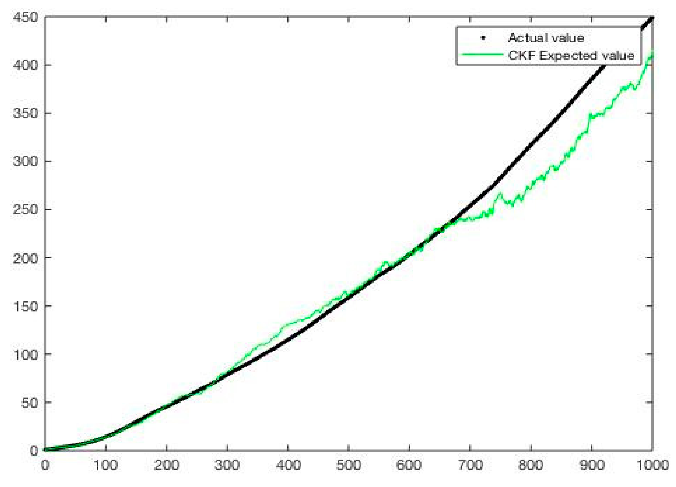
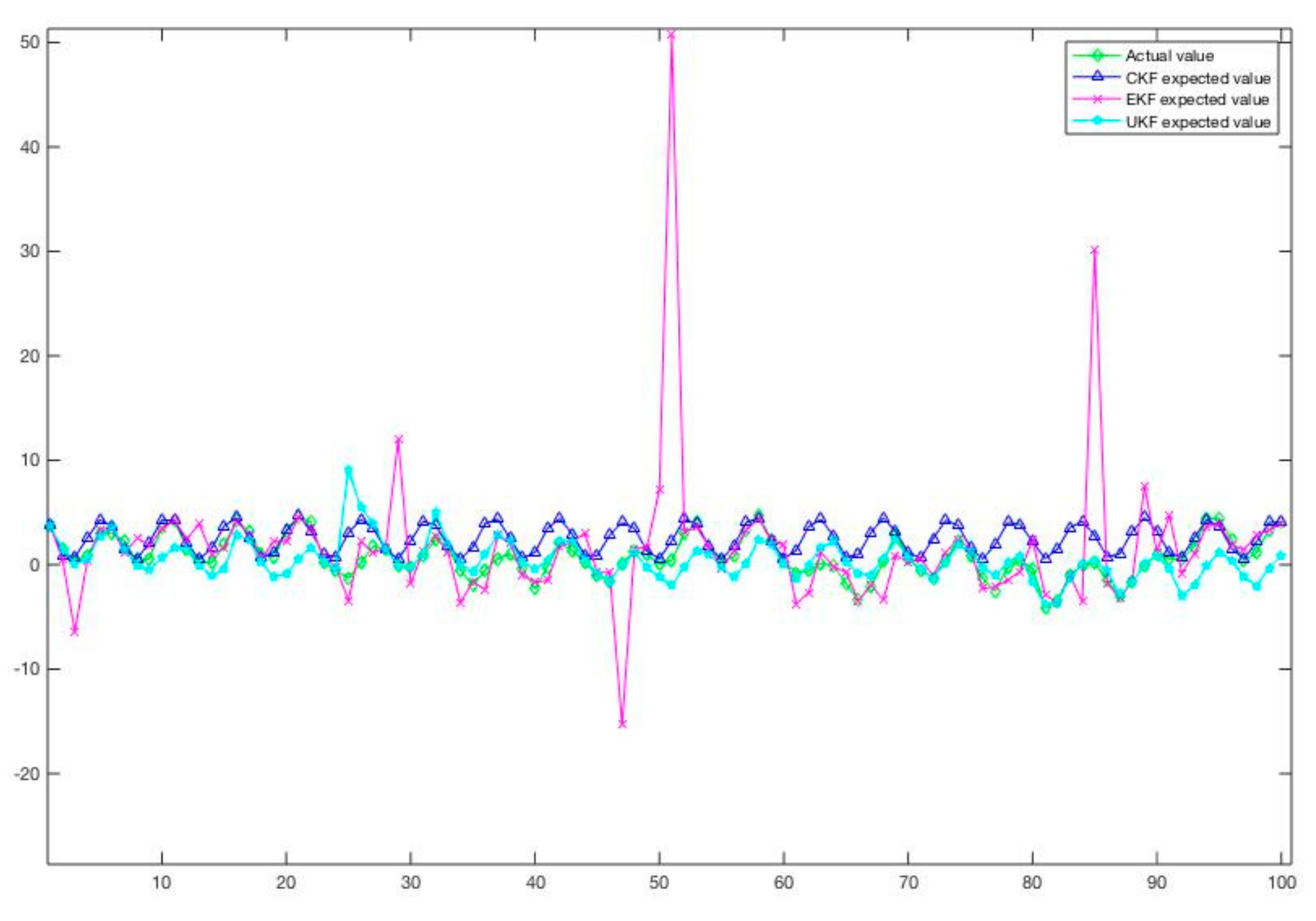
3.2. CKF-Based Combined Positioning Algorithm to Achieve Data Fusion

The combined positioning and fusion algorithm used in this paper uses the volumetric Kalman filter algorithm, which is roughly divided into two modules: time update and measurement update. Beidou and track signals are used as input to solve the algorithm, and the state variables of the filter in the data fusion process are dynamically modified. The output of the algorithm can be used as the initial value of the track estimation positioning in the next calculation cycle. The most important thing in the fusion positioning algorithm is to establish an accurate system model. In this paper, the vehicle positioning system is a non-linear system. The state equation and observation equation of the vehicle positioning system are established first.

3.2.1. Time Update Module

The vehicle positioning system in this section uses the state vector   X k , Y k , sin φ k , cos φ k T to describe the vehicle state. The vehicle’s speed sensor can be used to obtain travel distance information (distance equals the integral of speed over time). The gyroscope sensor is used to obtain the direction information of the vehicle in the process of traveling. X k , Y k is the position of the vehicle in the two-dimensional coordinate system at time k . φ k is the angle between the driving direction of the vehicle and the X -axis. Among them,   u k = Δ D k , Δ φ k T represents the calculated vehicle pose change. w k and v k represent system process errors, both of which are uncorrelated Gaussian white noise with zero mean.
X k + 1 = f X k , u k + w k
Z k = h X k , u k + v k
The state vector at k + 1 time and the state vector at the previous time can be analyzed separately in terms of linear motion and curved motion. The driving direction of the vehicle can be obtained by integrating the angular velocity output by the gyroscope sensor, which represents the change value of the steering angle of the vehicle from time k to time k + 1 , and t represents the sampling interval.
Δ φ k = k t k + 1 t ω τ d τ
φ k + 1 = φ k + Δ φ k
ω τ represents the angular velocity of the vehicle at time τ . Δ D k represents the distance traveled by the vehicle in the sampling interval between time k and k + 1 . It can be obtained by integrating the data and time output by the speedometer sensor.
Δ D k = k t k + 1 t v τ d τ
v τ represents the speed value output by the vehicle speedometer sensor at time τ . The coordinates of the vehicle at k + 1 can be calculated as follows.
X k + 1 = X k + k t k + 1 t v τ cos   φ τ d τ Y k + 1 = Y k + k t k + 1 t v τ sin   φ τ d τ
When the system determines that it is moving in a straight line, the deviation angle of the vehicle during the sampling interval is too small. Then, the relationship between the state vector at time k + 1 and the state vector at time k can be expressed as:
X k + 1 = X k + Δ D k cos   φ k + Δ φ k Y k + Δ D k sin   φ k + Δ φ k sin   φ k cos   φ k + W k
W k = w d cos φ k w d sin φ k 0 0
When the system is judged to be a curve motion, the system state vector relationship can be calculated and expressed as:
X k + 1 = X k + Δ D k Δ φ k   [ sin   φ k + Δ φ k sin   φ k Y k + Δ D k Δ φ k   cos φ k + Δ φ k + cos   φ k sin   φ k + Δ φ k cos   φ k + Δ φ k + W k
W k = w d   [ sin   φ k + Δ φ k sin   φ k w d   cos φ k Δ φ k + cos   φ k w θ cos   φ k + Δ φ k w θ sin   φ k + Δ φ k
The errors w d and w θ will be adjusted according to the actual displacement data of the left and right wheels moving on the ground during the filtering time k . The specific adaptive adjustment method can be derived in detail based on the literature of other scholars, and will not be repeated in this article.

3.2.2. Measurement Model

In Beidou/track combined positioning, the change in vehicle position can be obtained through the Beidou satellite or track sensor.
X B D Y B D = X k Y k + δ X k η Y k
In the observation equation, the former is the observation value in Beidou or the track, and the latter is the observation noise. The Beidou positioning observation noise is different from the track estimation observation noise, and ρ B D represents the noise of the Beidou positioning signal. The track estimation positioning error will not fluctuate greatly, and will only increase with the increase in the distance the vehicle moves. ε represents the noise variance coefficient of the Beidou signal. Therefore, it can be remembered that the variances of the observed noise and the system noise are, respectively,
σ X 2 k = σ Y 2 k = ε · ρ B D 2 + t k k t t k v τ d τ 2
σ 2 δ Δ D k = Q Δ D ,   σ 2 δ Δ φ k = Q Δ φ
Since the odometer calculates vehicle positioning information by accumulating movement increments, cumulative errors will inevitably occur, so the combined measurement model of the Beidou and track is adopted. Suppose the observation vector obtained by observation is Z M k = X , Y , φ T . The conversion relationship between observation information Z 1 k and Z 1 k 1 at time k can be calculated
Z 1 k = Z 1 k 1 + Δ D k cos φ k 1 + Δ φ k / 2 ] Δ D k sin φ k 1 + Δ φ k / 2 ] Δ φ k + v 1 k 1
v 1 k 1 = ω D cos φ k 1 + Δ φ k / 2 ] ω D sin φ k 1 + Δ φ k / 2 ] ω e
The observation information collected by Beidou is further expressed as:
Z 2 k = X k Y k + v 2 k
The Beidou signal sampling period is set to 1 s, and the time interval is 1 s, the coordinate position information of the combined positioning Z 1 k direction coordinate position variable and the coordinate position information of the observation information Z 2 k are averaged and merged to obtain the final volume. The observation vector Z of the Kalman filter system is Z = X , Y T .
Z 1 , k = 1 2 Z 1 1 , k + Z 2 1 , k , m o d k , 10 = = 0 Z 1 1 , k ,     m o d k , 10   ~ = 0
Z 2 , k = 1 2   Z 1 2 , k + Z 2 2 , k , m o d k , 10 = = 0 Z 1 2 , k ,     m o d k , 10   ~ = 0
The roadside unit positioning correction is to combine the position coordinates and driving direction based on Beidou and track estimation with the road network information. Video stream-based tracking technology has many application scenarios in intelligent transportation systems, and vehicle target detection is one of them. Therefore, the video sequence collected by the camera can be used as the input, and based on the result of the detection of the video frame by frame by the target detector, the method of feature extraction and data association can be used to realize the tracking of the vehicle target. The follow-up research plan of this paper includes the addition of the Interacting Multiple Model Algorithm (IMM), which evaluates the consistency of each model with the current maneuvering target according to the filter results, and then updates the model probability, and uses the model probability as the filter result. Based on the weighted calculation, the tracking and positioning effect is better than that of a single model.

4. Discussion

This article is based on the MATLAB 2019b software environment, and the volumetric Kalman filter CKF is used for the simulation experiment. Combining the picture results, it can be found that the Beidou/track positioning fusion algorithm based on CKF can improve the positioning accuracy of the vehicle. As time goes by, the positioning accuracy and positioning error can be controlled within an acceptable range. The lane-level positioning is basically achieved, and is significantly improved compared to the use of satellite navigation and positioning alone. Through experiments, it can be concluded that the Beidou/track combined positioning proposed in this paper is better than the independent positioning algorithm, and can achieve better stability and reliability.
In order to further optimize the positioning accuracy, it can be further combined with the feature extraction of traffic video stream information to achieve auxiliary enhancement of the effect. As an important part of the vehicle–road coordination system, the roadside unit level can realize the collection of road network information of urban traffic video streams based on the existing communication network. Therefore, algorithm processing can be carried out after the information is transmitted to the system platform. The scene clustering is completed by analyzing the video characteristics and fed back to the vehicle-mounted unit that has the information request to assist the vehicle–road coordinated positioning. The overall system architecture is shown in Figure 3, Figure 4 and Figure 5.

5. Conclusions

With the development of application scenarios such as smart transportation and autonomous driving, vehicle–road co-location technology is one of the basic capabilities that support its development. Therefore, it is necessary to further optimize the existing positioning solutions in combination with the constantly evolving communication network and vehicle–road co-location scenarios. With the completion of the Beidou system network, Beidou-based navigation and positioning will bring new impacts and changes to the traffic scene. In order to reduce the linear influence on system equations and state equations, this paper adopts volumetric Kalman filtering and other combined positioning methods to improve positioning accuracy. Cooperative localization utilizes the respective advantages of different positioning technologies to achieve the practical effect of learning from each other. Fusion of the advantages of satellite positioning and track estimation and the fusion of volume-based Kalman-based data helps to smooth the vehicle positioning trajectory. At the same time, the idea of slicing is proposed to provide a better resource allocation strategy for the information transmission of the traffic road network. This supports more flexible and diverse vehicle positioning scenarios in the 5G era, helping navigation and positioning systems to be more efficient and intelligent.

Author Contributions

Conceptualization, Z.M. and S.S.; methodology, Z.M.; software, Z.M.; validation, Z.M.; formal analysis, Z.M.; investigation, Z.M.; resources, S.S.; data curation, Z.M. writing—original draft preparation, Z.M.; writing—review and editing, Z.M.; visualization, Z.M.; supervision, S.S.; project administration, S.S. All authors have read and agreed to the published version of the manuscript.

Funding

This research received no external funding.

Institutional Review Board Statement

Not applicable.

Informed Consent Statement

Not applicable.

Data Availability Statement

Not applicable.

Conflicts of Interest

The authors declare no conflict of interest.

References

  1. Hettikankanama, H.K.S.K.; Vasanthapriyan, S. Integrating Smart Transportation System for a Proposed Smart City: A Mapping Study. In Proceedings of the 2019 International Research Conference on Smart Computing and Systems Engineering (SCSE), Colombo, Sri Lanka, 28 March 2019; pp. 196–203. [Google Scholar] [CrossRef]
  2. Tadic, S.; Favenza, A.; Kavadias, C.; Tsagaris, V. GHOST: A novel approach to smart city infrastructures monitoring through GNSS precise positioning. In Proceedings of the 2016 IEEE International Smart Cities Conference (ISC2), Trento, Italy, 12–15 September 2016; pp. 1–6. [Google Scholar] [CrossRef]
  3. Ding, Y.; Zhou, D.; Wang, H.; Jiang, Y.; Jiang, Y.; Ma, X. Vehicle Aided Positioning Method Based on Intelligent Identification. In Proceedings of the 2019 34rd Youth Academic Annual Conference of Chinese Association of Automation (YAC), Jinzhou, China, 6–8 June 2019; pp. 493–498. [Google Scholar] [CrossRef]
  4. Liu, S.; He, D.; Xu, Y.; Zhang, C.; Sun, S.; Ru, D. Adaptive Vehicle Cooperative Positioning System with Uncertain GPS Visibility and Neural Network-based Improved Approach. In Proceedings of the 2018 IEEE/CIC International Conference on Communications in China (ICCC Workshops), Beijing, China, 16–18 August 2018; pp. 303–308. [Google Scholar]
  5. Gerges, R.L.; Shynk, J.J.; Hwang, S.-S. High-accuracy vehicle position estimation using a cooperative algorithm with anchors and probe vehicles. In Proceedings of the 2015 49th Asilomar Conference on Signals, Systems and Computers, Pacific Grove, CA, USA, 8–11 November 2015; pp. 661–665. [Google Scholar]
  6. Shieh, W.-Y.; Hsu, C.-C.J.; Lin, C.-H.; Wang, T.-H. Investigation of Vehicle Positioning by Infrared Signal-Direction Discrimination for Short-Range Vehicle-to-Vehicle Communications. IEEE Trans. Veh. Technol. 2018, 67, 11563–11574. [Google Scholar] [CrossRef]
  7. Wu, X.; Wang, X.; Lu, H.; Li, J. Study on application status and standard system of BDS in transportation. In Proceedings of the 2017 Forum on Cooperative Positioning and Service (CPGPS), Harbin, China, 19–21 May 2017; pp. 167–173. [Google Scholar] [CrossRef]
  8. Park, C.-H.; Han, J.-H. Performance Evaluation of GNSS and Motion Sensor Integrated Positioning Algorithm for Land Vehicle Monitoring. In Proceedings of the 2020 International Conference on Information and Communication Technology Convergence (ICTC), Jeju, Korea, 21–23 October 2020; pp. 1592–1595. [Google Scholar]
  9. Soatti, G.; Nicoli, M.; Garcia, N.; Denis, B.; Raulefs, R.; Wymeersch, H. Implicit Cooperative Positioning in Vehicular Networks. IEEE Trans. Intell. Transp. Syst. 2018, 19, 3964–3980. [Google Scholar] [CrossRef] [Green Version]
  10. Jia, W.; Cai, C.; Wu, Q.; Li, S.; Zheng, J. Research on High Precision Dynamic Relative Positioning Technology Based on the Third Generation BDS. In Proceedings of the 2020 IEEE 3rd International Conference of Safe Production and Informatization (IICSPI), Chongqing, China, 28–30 November 2020; pp. 304–312. [Google Scholar]
  11. Lim, J.; Choi, K.H.; Kim, L.; Lee, H.K. Land vehicle positioning in urban area by integrated GPS/BeiDou/OBD-II/MEMS IMU. In Proceedings of the 2016 IEEE International Conference on Intelligent Transportation Engineering (ICITE), Singapore, 20–22 August 2016; pp. 176–180. [Google Scholar]
  12. Luo, K.; Zhong, M.; Yang, Y. Combined Positioning Method of Port AGV based on Beidou Difference and Inertial Navigation Technology. In Proceedings of the 2019 International Conference on Sensing and Instrumentation in IoT Era (ISSI), Lisbon, Portugal, 29–30 August 2019; pp. 1–6. [Google Scholar]
  13. Rivera, J.J.D.; Khan, T.A.; Mehmood, A.; Song, W.-C. Network Slice Selection Function for Data Plane Slicing in a Mobile Network. In Proceedings of the 2019 20th Asia-Pacific Network Operations and Management Symposium (APNOMS), Matsue, Japan, 18–20 September 2019; pp. 1–4. [Google Scholar]
  14. Martiradonna, S.; Abrardo, A.; Moretti, M.; Piro, G.; Boggia, G. Architecting RAN Slicing for URLLC: Design Decisions and Open Issues. In Proceedings of the 2019 IEEE/ACM 23rd International Symposium on Distributed Simulation and Real Time Applications (DS-RT), Cosenza, Italy, 7–9 October 2019; pp. 1–4. [Google Scholar]
  15. Mouawad, N.; Naja, R.; Tohme, S. Inter-Slice Mobility Management Solution In V2X Environment. In Proceedings of the 2019 International Conference on Wireless and Mobile Computing, Networking and Communications (WiMob), Barcelona, Spain, 21–23 October 2019; pp. 1–6. [Google Scholar]
  16. Vilalta, R.; Alemany, P.; Sedar, R.; Kalalas, C.; Casellas, R.; Martinez, R.; Vazquez-Gallego, F.; Ortiz, J.; Skarmeta, A.; Alonso-Zarate, J.; et al. Applying Security Service Level Agreements in V2X Network Slices. In Proceedings of the 2020 IEEE Conference on Network Function Virtualization and Software Defined Networks (NFV-SDN), Leganes, Spain, 10–12 November 2020; pp. 114–115. [Google Scholar]
  17. Kourtis, M.-A.; Anagnostopoulos, T.; Kuklilski, S.; Wierzbicki, M.; Oikonomakis, A.; Xilouris, G.; Chochliouros, I.P.; Yi, N.; Kostopoulos, A.; Tomaszewski, L.; et al. 5G Network Slicing Enabling Edge Services. In Proceedings of the 2020 IEEE Conference on Network Function Virtualization and Software Defined Networks (NFV-SDN), Leganes, Spain, 10–12 November 2020; pp. 155–160. [Google Scholar]
  18. Fan, Y.; Wang, P.; Yu, J.; Wang, S.; Yu, W.; Li, J.; Yan, N.; He, D.; Chen, X. Accuracy Analysis on the Beidou /INS Integrated Navigation based on the Field Trial. In Proceedings of the 2018 IEEE 23rd International Conference on Digital Signal Processing (DSP), Shanghai, China, 19–21 November 2018; pp. 1–5. [Google Scholar]
  19. Wang, S.; Zhang, H.; Shihui, Z.; Wang, B. Passive Localization Method Based on Cubature Kalman Filter. In Proceedings of the 2020 39th Chinese Control Conference (CCC), Shenyang, China, 27–29 July 2020; pp. 650–654. [Google Scholar]
  20. Abosekeen, A.; Noureldin, A.; Korenberg, M.J. Improving the RISS/GNSS Land-Vehicles Integrated Navigation System Using Magnetic Azimuth Updates. IEEE Trans. Intell. Transp. Syst. 2019, 21, 1250–1263. [Google Scholar] [CrossRef]
  21. Ravipati, D.; Chour, K.; Nayak, A.; Marr, T.; Dey, S.; Gautam, A.; Rathinam, S.; Swaminathan, G. Vision Based Localization for Infrastructure Enabled Autonomy. In Proceedings of the 2019 IEEE Intelligent Transportation Systems Conference (ITSC), Auckland, New Zealand, 27–30 October 2019; pp. 1638–1643. [Google Scholar]
Figure 1. The architecture of the vehicle network slicing system.
Sustainability 13 05334 g001
Figure 2. The proposed algorithm flow framework and research methods.
Sustainability 13 05334 g002
Figure 3. Comparison chart of the program proposed in this article and the actual position error.
Sustainability 13 05334 g003
Figure 4. The Data performance of different filtering methods.
Sustainability 13 05334 g004
Figure 5. The proposed overall system architecture.
Sustainability 13 05334 g005
Publisher’s Note: MDPI stays neutral with regard to jurisdictional claims in published maps and institutional affiliations.

