Article

Project and Implementation of an Educational Large-Scale Water Distillation Unit with a Closed-Circuit Condenser

by
Luís Carlos Matos
1,*,†,
Ana Eulálio
1,†,
Tiago Antunes
1,†,
José Miguel Loureiro
2,
Alexandre Ferreira
2 and
Adélio Mendes
3,*
1
Faculdade de Engenharia, Universidade do Porto, Rua Dr. Roberto Frias, s/n 4200-465 Porto, Portugal
2
Laboratory of Separation and Reaction Engineering-Laboratory of Catalysis and Materials (LSRE-LCM), Department of Chemical Engineering, University of Porto, Rua Dr. Roberto Frias, s/n 4200-465 Porto, Portugal
3
LEPABE, Departamento de Engenharia Química, Faculdade de Engenharia, Universidade do Porto, Rua Dr. Roberto Frias, s/n 4200-465 Porto, Portugal
*
Authors to whom correspondence should be addressed.
These authors contributed equally to this paper.
Sustainability 2020, 12(8), 3239; https://doi.org/10.3390/su12083239
Submission received: 21 March 2020 / Revised: 11 April 2020 / Accepted: 13 April 2020 / Published: 16 April 2020

Abstract

:
Water is one of the scarcest resources in the world, and it is becoming rarer fast, year after year. Chemical engineers are particularly suited to addressing the challenges of saving water and producing more fresh water. Proper education is then critical to prepare them for the upcoming decades. All student laboratories need distilled water, which is typically produced using commercial distillation units, which consume up to 70 L of fresh water per liter of distillated water. This work reports the design, construction, optimization, and operation of a water distillation unit that produces 10 liters per hour at 4 µS∙cm−1 and wastes no fresh water. Developed by a committed team made up of students, lab technicians, and instructors, this unit saves ca. 550 m3 of fresh water annually while spending less electrical power.

1. Introduction

According to the United Nations, the average daily consumption of fresh water, per person, in the United States and Europe is between 400 and 600 liters [1]. According to the World Resources Institute, within 20 years, the South of Europe and the United States will have to deal with an extremely high risk of water stress, meaning that the demand for water will exceed the available resources [2]. Over the past century, water consumption has increased twice as fast as the rate of population growth. Although water scarcity is partially of natural origin, related to its uneven distribution, most of it has an anthropogenic origin, as fresh water is quite often wasted, polluted, and unsustainably managed [3,4]. Water is, and will always be, a valuable resource that must be used wisely.
Sustainability is of growing concern worldwide, mainly among younger generations [5,6]. Nevertheless, creative ways to create awareness are needed. With these concerns in mind, several authors have tried to reduce water usage in laboratory practices. Schoeddert et al. [7] designed a low-cost, easy to make recirculation system for a condenser apparatus, which allows for saving over 14.4 m3 of cooling water per year. The system was designed for organic chemistry labs and relied on gravity and a small pump to circulate the cooling water between an upper and a lower reservoir while supplying four different workstations at the same time. Baum et al. [8,9] modified the traditional condensers used in chemistry laboratories to waterless condensers. First, they used ethylene glycol in a closed condenser as a cooling storage medium, obtaining similar solvent retentions as with a conventional water condenser. Then, using concentrated antifreeze in a closed circuit, they were able to obtain the same separation as conventional condensers using flowing water. The implementation of these condensers can save approximately 13 m3 of water per year at the laboratories of Butler University. Chan et al. [10] stated that distillation has a considerable impact on water consumption at student and research labs, and most people involved are not aware of that. Among the distillation processes, the production of distilled water is probably the most water-wasting process. For example, at the Chemical Engineering Department at the University of Porto, the daily consumption of distilled water is around 30 L. To produce this amount of distilled water using a conventional glass distillation apparatus, it would be necessary to waste ca. 550 m3 of cooling water yearly, i.e., each liter of distilled water requires ca. 70 L of cooling water. To avoid wasting such a large amount of water, a larger scale distillation system in which no water is wasted was developed.
Currently, the most popular teaching method relies on classic lectures with a presentation of concepts and little to no involvement from the students. Despite this, active learning, where students are directly involved with the subject rather than being passive receptors, has been proven to help students retain concepts and information [7]. Well-designed laboratories for undergraduate engineering programs are essential to achieving pedagogical success. They are considered to be a standard in every area of knowledge of chemical engineering degrees, not only at the University of Porto, but also at other well-ranked universities. From Fluid Mechanics, Heat Transfer [11,12], Separation Processes [13], Reaction Engineering [14], and Heterogeneous Catalysis [15] to Corrosion and Materials Science [16], just to mention a few, the commitment to developing and implementing well-designed educational experiments is critical to providing the conditions to develop hands-on skills. This is not only often reflected by well-ranked student marks, but also by the student response to pedagogical surveys, or even by the feedback given by future employers and professional internship supervisors.
The main goal of this work is to report on the implementation of a large-scale water distillation unit with a closed-circuit condenser, which is used both for educational purposes and as a piece of departmental utility equipment to produce and supply distilled water. The refrigerated water flowing in a closed-circuit condenser exchanges heat with a large water reservoir, which supplies the entire school with fresh water. The equipment was designed to be used during field-trip visits, by undergraduate students attending Chemical Engineering Practices. It integrates concepts of separation processes, heat transfer, control and instrumentation, and industrial design while showing how every process can be improved and made more sustainable and eco-friendly. Besides its pedagogical purposes, the equipment, with a production capacity of 10 liters per hour, is used daily to supply research and educational laboratories. By replacing the conventional glass distillation apparatus, which has open-circuit condensers, by this one with the closed-circuit condenser, the consumption of electricity and refrigeration water was reduced considerably while maintaining the quality of the distilled water.

2. Materials and Methods

The distillation unit is made of stainless steel and has a reboiler and a condenser, as shown in Figure 1. The condenser has two coils, one for preheating the feeding water and the other for condensing the steam. The preheating of the feeding water saves electrical energy because the reboiler needs less power. The reboiler has a total water volume of ca. 25 liters when operating at 80% of its capacity. It has two heating resistors of 3000 W each, threaded to each end side (38.1 mm diameter gas threads), and a Pt100 sensor that is inserted laterally for temperature control.
The closed-circuit refrigeration system is composed of an internal and an external coil. The internal coil is used for preheating the feeding water while the external coil is used for condensing the water vapor evolving from the reboiler. A magnetic centrifugal pump (Pan-World, model NH50PX-H) pumps the cooling water—thermal fluid. The external coil, with a total length of 2.8 m, has 6 turns with a diameter of 150 mm and an angle of 20°, resulting in a height of about 1 m (Figure 1). This coil is submerged in the freshwater reservoir of the Faculty of Engineering, which has a capacity of ca. 100 m3 (Figure 2). The cooling system is made of 22 mm internal diameter tubes. To avoid oxidation, most of the components are made of stainless steel 316 L.

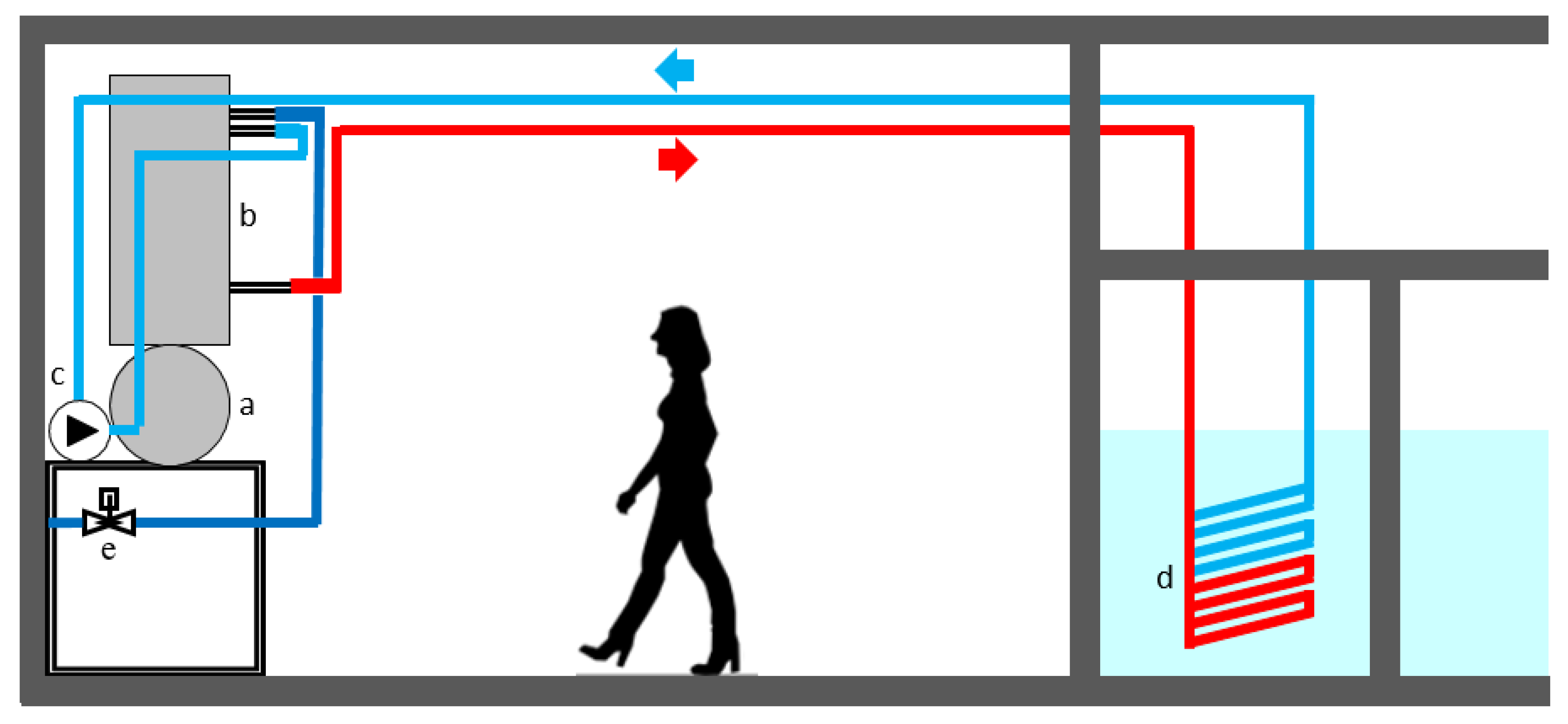
2.1. Design of the Distillation Unit

The calculation procedure used to design the preheating coil and the internal and external cooling coils is described in detail in Appendix A.

2.2. Control and Instrumentation of the Distillation Unit

The distillation system is controlled locally using a logic module (Siemens, LOGO! 230 RC). This module is connected to a computer using an acquisition card (NI DAQ 6008) and controlled using an in-house developed program on the LabVIEW platform. Since the computer is connected to the internet, the controlling program can be accessed locally or remotely. The logic module is connected to three solid-state relays, which control the magnetic drive centrifugal pump and the two heating resistors, and to a signal transmitter/amplifier (B.UP 215 C/2MT) connected to a Pt100 sensor (Figure 3).
The water level inside the reboiler and the activation of the heating resistors are controlled by a floater probe with two levels, minimum and maximum. The probe is connected to two relay switches that activate two contactors (one for each heating resistor) and the water supply on/off solenoid valve. The minimum level was set to 30 mm above the resistors, which are installed 20 mm above the base of the reboiler. The maximum level was set to 180 mm above the base of the reboiler.
The control of the water level in the reboiler and the activation of the heating resistors are done according to the block diagram shown in Figure 4.
Briefly, with the floater at the minimum level, the resistors are off and the solenoid valve—for the inlet water—opens. Water starts being fed to the reboiler, which makes the floater gradually rise. When the water reaches a set-point level (the minimum level is turned off), the solenoid valve is closed, and the heating resistors are turned on. At this moment, a timer is also activated at the Siemens logic module or the LabVIEW program, depending on which system is being used to control the operation. The timer switches on and off the relay that activates the water feed solenoid valve (off for 2 min, on for 20 s). When the floater reaches the upper level (the maximum level), the solenoid valve is closed, and water is only fed to the system when the minimum level is reached once again.

3. Results and Discussion

3.1. Distillation Unit Design

Table 1 shows different preheating coil dimensions suitable for performing the preheating job. A coil with a diameter of 150 mm and a length of 2.5 m was chosen since it displays the best size to fit in the condenser envelope. The total height of this coil is 0.92 m, with 5.5 turns. These values were obtained using the model described in Appendix A. For example, the first design in Table 1 was obtained assuming that the preheating coil diameter was 0.08 m. Using Equation (A9), it was possible to calculate the internal heat transfer coefficient of the coil, which is 323 W∙m−2∙°C−1. The external heat transfer coefficient was computed with Equations (A10) and (A11), and the highest value between the two was then used in the following steps–-the worst-case scenario. In this case, the values of hext were 10,279 W∙m−2∙°C−1 and 6845 W∙m−2∙°C−1 for horizontal and vertical tubes, respectively. The value of 1 U A i n t was calculated using Equation (A13), resulting in 0.0740 °C∙W−1. Then, Equation (A14) was solved to obtain the length of the pre-heating tube, L. The obtained value of L was 2.20 m.
Table 2 shows different internal cooling coil designs suitable for performing the cooling task. Again, a coil with a diameter of 250 mm was chosen since it fits well inside the condenser vessel; the final design considers a coil length of 2.8 m, a height of 0.92 m, and 6 turns. The first design in Table 2 was obtained assuming, once again, that the preheating coil diameter was 0.08 m. Using Equation (A19), it was possible to calculate the internal heat transfer coefficient of the coil, which is 1716 W∙m−2∙°C−1. The external heat transfer coefficient was computed with Equations (A10) and (A11); the highest value between the two was then used in the following steps—the worst-case scenario. The values of hext were 8609 W∙m−2∙°C−1 and 7294 W∙m−2∙°C−1 for horizontal and vertical tubes, respectively. The value of 1 U A i n t was calculated using Equation (A18), resulting in 0.0062 °C∙W−1. Then, Equation (A14) was solved to obtain the length of the pre-heating tube, L. The obtained value of L was 2.08 m.

3.2. Reboiler Heating and Performance Analysis

After the water level in the reboiler reaches the minimum level, the heating resistors switch on automatically, as do the recirculating pump and the solenoid valve (Figure 2). Figure 5 shows the temperature history of the water in the reboiler, which accounts for the input heat from the resistances and the continuous inlet of water; the inlet of water only stops when the maximum set-point level is reached. From this moment on, the temperature increases linearly until the water starts boiling at 100 °C. The temperature history equation, also plotted in Figure 5, is:
t = m C p Δ T P
where P is the total power of the heating resistors.
This distillation unit produces water with very low conductivity (between 4 and 5 µS∙cm−1) and does not waste water in the condenser. This is a significant improvement compared with the previously used distillation units, which needed 70 liters of water passing through the condenser to produce one liter of distilled water.

3.3. Economic Analysis

An economic analysis was performed considering the investment costs and the operating costs, as shown in Table 3; Table 4, respectively.
This distillation unit replaces the use of three conventional water distillation units, such as the Merit Water Still/W4000, suitable for producing ca. 10 L of distilled water per hour. The latter has a total cost of 3350 euros, and its operating costs are illustrated in Table 5.
Even though the investment costs are higher for the closed-circuit distillation unit, the operating costs are 46% of the expenses for the three traditional water distillation units, resulting in a return of investment (ROI) of ca. 10 months, assuming an annual distilled water production volume of 550 m3.

4. Conclusions

A water distillation unit with a closed-circuit refrigeration system was designed, built, and validated. The developed unit wastes no water for condensing the formed steam since it uses a thermal fluid to transfer the heat to a freshwater reservoir with ca. 100 m3 at the Faculty of Engineering, University of Porto. The distillation unit was designed and assembled by the staff and produces high-quality distilled water with a conductivity of 4 μS·cm−1. Compared with conventional lab distillation units, which can consume up to 70 L of fresh water per liter of distilled water, the developed distillation unit saves ca. 500 m3 of fresh water per year, displaying a ROI of ca. 10 months.
Designing a water distillation system may seem like an easy task for undergraduate students, but it requires a strong background in heat transfer and instrumentation. In the framework of Chemical Engineering Laboratories, students at the University of Porto are required to propose strategies for saving water and, in the end, are invited to visit this distillation unit, where they learn about its design, instrumentation, suppliers, and advantages. Back in the classroom, students are required to solve a water distillation problem similar to the one described in this work.

Author Contributions

A.M. and L.C.M. conceived and designed the distillation unit; L.C.M. coordinated the implementation of the equipment and experiments; L.C.M., A.E., T.A., J.M.L., A.F., and A.M. analyzed the data; L.C.M., A.E., T.A. wrote the paper; L.C.M., A.E., T.A., J.M.L., A.F., and A.M. revised the article and contributed to the final version. All authors have read and agreed to the published version of the manuscript.

Funding

This research was funded by the Chemical Engineering Department at the Faculty of Engineering, University of Porto, by Base Funding UIDB/00511/2020 of the Laboratory for Process Engineering, Environments, Biotechnology and Energy (LEPABE) funded by national funds through the FCT/MCTES (PIDDAC), by Base Funding UIDB/50020/2020 of the Associate Laboratory LSRE-LCM, funded by national funds through FCT/MCTES (PIDDAC), and by SunStorage—Harvesting and storage of solar energy, with reference POCI-01-0145-FEDER-016387, funded by European Regional Development Fund (ERDF), through COMPETE 2020—Operational Programme for Competitiveness and Internationalisation (POCI), and by national funds, through FCT—Fundação para a Ciência e a Tecnologia I.P.

Conflicts of Interest

The authors declare no conflicts of interest.

Appendix A: Design of the Distillation Unit

A.1. Preheating Coil Design

The heat balance to the reboiler is:
Q total = Q condensation + Q refrigeration
and,
Q condensation = m ˙ λ
where Q is the heat flow, m ˙ is the mass flowrate, and λ is the latent heat of vaporization, and
Q refrigeration = m ˙ C p Δ T
where C P is the specific heat and Δ T is the temperature difference between the outlet and inlet temperature of the thermal fluid.
The heat exchanged between the feed water and the evolving steam in the condenser was calculated using the average temperature between the inlet and the outlet of the feed water stream. For this purpose, the inlet temperature was considered to be 20 °C, and the outlet temperature, just before entering the reboiler, was assumed to be 75 °C. The inlet water flow velocity can be estimated from the internal coil tube diameter, which is 6.4 mm:
v = m ˙ A c s   ρ
where ρ is the density and Acs is the cross-section area of the preheating tube.
To calculate the length needed to achieve the desired temperature increase, it is necessary to assume that the feeding coil is a straight tube, and it is essential to determine the internal (a) and external (b) heat transfer coefficients.
(a) Determination of the Internal Heat Transfer Coefficient [17]:
Nu = h i n t d k
where hint is the internal heat transfer coefficient, k is the thermal conductivity of water, d is the internal diameter, and Nu is the Nusselt number. The latter can be calculated based on dimensionless parameters:
Re = ρ v d μ
Pr = C p μ k
where Re and Pr are the Reynolds and Prandtl numbers, respectively, and μ is the viscosity of the water in the bulk. These dimensionless numbers are correlated through the following Equation:
Nu = 1.86 ( R e   P r ) 1 3   ( d L ) 1 3   ( μ μ w ) 0.14
where μ w is the viscosity of the water at the wall and L is the length of the tube.
Since the heat exchange tube is coiled, not straight, a better prediction of hint can be obtained from Equation (A9):
h i n t ( coil ) = h i n t ( straight   tube ) ( 1 + 3.5 d d c )
where d c is the coil diameter.
(b) Determination of the External Heat Transfer Coefficient:
For horizontal tubes [17]:
h e x t = 0.72 ( λ k 3 ρ 2 g d e x t Δ T μ ) 1 4
where g is the gravitational acceleration and d e x t is the external diameter of the tube, 8.4 mm. For vertical tubes [17]:
h e x t = 0.943 ( λ k 3 ρ 2 g l Δ T μ ) 1 4
where l is a semi-length calculated as follows:
l = π d c 2
From hint, hext, and the overall energy balance:
Q = U A i n t Δ T l m
where Q is the heat removed by the feed water, U is the overall heat transfer coefficient, Aint is the internal area of the tube, and Δ T l m is the logarithmic mean temperature difference. The length of the tube can then be calculated from Equation (A14):
1 U A i n t = 1 h i n t A i n t + x w k w A w + 1 h e x t A e x t
where x w is the thickness of the coil wall, k w is the thermal conductivity of the coil wall, A e x t is the external area of the coil, and A w is the logarithmic mean area of the coil, which can be calculated from
A w = A e x t A i n t ln A e x t A i n t
The model defined by Equations (A1)–(A14) has an implicit solution. For solving it, the optimization tool Solver of MS Office Excel was used.

A.2. Cooling Coils Design

The external (b) and internal (a) cooling coils were designed considering the most demanding ambient conditions, which happens when the water temperature of the freshwater reservoir is the highest during summertime. It was assumed that the cooling water temperature was 30 °C and the exiting cooling water temperature was 75 °C. The required water flow rate to condense the steam and cool down the distilled water can be calculated as follows:
m ˙ c c = Q total C p Δ T
and the water velocity in the closed circuit (vcc) can then be calculated:
v c c = m c c ˙ A c s , c c   ρ
where A c s , c c is the cross-section area of the closed-circuit tube.
The overall heat transfer coefficient of the cooling coils (Ucc) was calculated according to Equation (A18):
U c c = Q total A i n t , c c Δ T l m
where A i n t , c c is the internal area of the closed-circuit system.
(a) Determination of the Internal Heat Transfer Coefficient [17]:
Nu = 0.023   ( R e ) 0.8   ( P r ) 0.4
valid for Re > 10,000 and 0.7 < Pr < 160.
After calculating h i n t ,   c c for a straight tube, this value was converted for a coil shape using Equation (A9).
(b) Determination of the External Heat Transfer Coefficient
The external heat transfer coefficient was computed using Equations (A10)–(A12). The data required for solving the models are indicated in Table A1.
Table A1. Data required to solve the model presented.
ConstantsValues
m ˙ (kg∙s−1)2.78∙10−3
λ (kJ∙kg−1)2.257∙103
C p (J∙kg−1∙°C−1)4181
ρ (kg∙m3)987
k (W∙m−1∙°C−1)0.647
μ (Pa∙s)5.3∙10−4
μ w (Pa∙s)3.186∙10−4
g (m∙s−2)9.8
k w (W∙m−1∙°C−1)16.3

References

  1. Escobar, I.C. Chapter 1 An Overview of the Global Water Situation. In Sustainability Science and Engineering; Elsevier: Amsterdam, The Netherlands, 2010; Volume 2, pp. 3–5. [Google Scholar] [CrossRef]
  2. Aqueduct Projected Water Stress Country Rankings | World Resources Institute. Available online: https://www.wri.org/resources/data-sets/aqueduct-projected-water-stress-country-rankings (accessed on 16 February 2020).
  3. UNDESA. Water scarcity | International Decade for Action ‘Water for Life’ 2005–2015. Available online: https://www.un.org/waterforlifedecade/scarcity.shtml (accessed on 9 April 2020).
  4. Liu, J.; Yang, H.; Gosling, S.N.; Kummu, M.; Flörke, M.; Pfister, S.; Hanasaki, N.; Wada, Y.; Zhang, X.; Zheng, C.; et al. Water scarcity assessments in the past, present, and future. Earth’s Future 2017, 5, 545–559. [Google Scholar] [CrossRef] [PubMed]
  5. Song, Y.; Qin, Z.; Yuan, Q. The impact of eco-label on the young Chinese generation: The mediation role of environmental awareness and product attributes in green purchase. Sustainability 2019, 11, 973. [Google Scholar] [CrossRef] [Green Version]
  6. Brock, A. Education for Sustainable Development in Germany: Not Just Desired but Also Effective for Transformative Action. Sustainability 2020, 12, 2838. [Google Scholar]
  7. Schoeddert, A.; Babooram, K.; Pelletier, S. Reduction of Water Waste in an Organic Chemistry Laboratory Using a Low-Cost Recirculation System for Condenser Apparatus. J. Chem. Educ. 2019, 96, 180–182. [Google Scholar] [CrossRef]
  8. Baum, E.W.; Esteb, J.J.; Wilson, A.M. Waterless Condensers for the Teaching Laboratory: An Adaptation of Traditional Glassware. J. Chem. Educ. 2014, 91, 1087–1088. [Google Scholar] [CrossRef]
  9. Baum, E.W.; O’Callaghan, I.; Cinninger, L.; Esteb, J.J.; Wilson, A.M. Static fluid condensers for the containment of refluxing solvent. ACS Sustain. Chem. Eng. 2013, 1, 1502–1505. [Google Scholar] [CrossRef]
  10. Leal Filho, W. Living Labs for Sustainable Development: The Role of the European School of Sustainability Sciences and Research. In World Sustainability Series; Springer: Berlin/Heidelberg, Germany, 2020; pp. 3–9. [Google Scholar] [CrossRef]
  11. Alves, M.; Pinto, A.G.D.C.J. Two Simple Experiments for the Fluid Mechanics and Heat Transfer Laboratory Class. Chem. Eng. Educ. 1999, 33, 226–231. [Google Scholar]
  12. Kasumu, A.S.; Nassar, N.N.; Mehrotra, A.K. A heat-transfer laboratory experiment with shell-and-tube condenser. Educ. Chem. Eng. 2017, 19, 38–47. [Google Scholar] [CrossRef]
  13. Narang, A.; Ben-Zvi, A.; Afacan, A.; Sharp, D.; Shah, S.L.; Huang, B. Undergraduate design of experiment laboratory on analysis and optimization of distillation column. Educ. Chem. Eng. 2012, 7, e187–e195. [Google Scholar] [CrossRef]
  14. Macey, A.; Gurguis, N.; Tebboth, M.; Shah, P.S.; Chesi, C.; Shah, U.V.; Brechtelsbauer, C. Teaching reaction kinetics with chemiluminescence. Educ. Chem. Eng. 2018, 22, 53–60. [Google Scholar] [CrossRef]
  15. Mendes, A.; Magalhães, F.; Madeira, L. Sucrose Inversion: An Experiment on Heterogeneous Catalysis*. Int. J. Eng. Educ. 2003, 19, 893–901. [Google Scholar]
  16. Matos, L.C.; Martins, J.I. Analysis of an Educational Cathodic Protection System with a Single Drainage Point: Modeling and Experimental Validation in Aqueous Medium. Materials (Basel). 2018, 11, 2099. [Google Scholar] [CrossRef] [PubMed] [Green Version]
  17. Coulson, J.M.; John, M.; Richardson, J.F.; John, F. Chemical Engineering; Pergamon Press: Oxford, UK, 1979. [Google Scholar]
Figure 1. The closed-circuit refrigeration system; Actual photos of the reboiler and condenser (A and B); Solidworks project (C—front view; D—top view; E—lateral view); and the corresponding design with dimensions in centimeters (F): a. heating resistors; b. Pt100; c. floater sensor; d. rock-wool insulation space.
Sustainability 12 03239 g001
Figure 2. Representation of the closed-circuit refrigeration system (red—hot stream; light blue—cold stream); a. reboiler; b. condenser; c. magnetic drive centrifugal pump; d. refrigeration coil submerged in the freshwater storage tank; e. solenoid valve controlling water admission to the distillation unit (dark blue).
Sustainability 12 03239 g002
Figure 3. Scheme of the implemented control system; 1. logic module; 2. solenoid on–off valve; 3. temperature controller; 4. floater level sensor; 5. Pt100; 6. three-phase contactor; 7. electromechanical relay; 8. circuit breaker; 9. power supply; 10. heating resistance; 11. safety switch; 12. warning light-emitting diodes (LED).
Sustainability 12 03239 g003
Figure 4. Block diagram of the water level and temperature control.
Sustainability 12 03239 g004
Figure 5. Temperature history at the beginning of the distillation process.
Sustainability 12 03239 g005
Table 1. Different preheating coil dimensions suitable for performing the preheating task.
Coil Diameter (m)Horizontal TubeVertical Tube
Length (m)No. of TurnsLength (m)No. of TurnsSemi-Length (m)Total Length (m)No. of Turns
0.082.209.02.2210.00.132.219.0
0.102.297.52.328.50.162.318.0
0.122.366.52.407.50.192.387.0
0.152.445.52.476.00.242.456.0
0.182.495.02.495.50.282.515.0
0.212.524.52.525.00.332.554.5
0.242.554.02.554.50.382.584.0
0.272.583.52.584.00.422.604.0
0.302.603.02.653.50.472.623.5
Table 2. Different internal cooling coil dimensions suitable for performing the cooling task.
Coil Diameter (m)Horizontal TubesVertical Tubes
Length (m)No. of TurnsLength (m)No. of TurnsSemi-Length (m)Total Length (m)No. of Turns
0.082.084.52.136.50.132.105.0
0.102.234.02.305.50.162.274.5
0.122.353.52.444.50.192.404.0
0.152.503.02.604.00.242.553.5
0.182.602.52.733.50.282.663.0
0.212.692.52.833.00.332.762.5
0.252.782.02.933.00.392.852.5
0.282.832.03.002.50.442.912.0
0.312.871.53.052.00.492.962.0
Table 3. Investment costs of the distillation unit.
ServiceSubtotal (€)
Distillation unit with closed-circuit condenser1908
Automation and control269
Total2177
Table 4. Annual operating costs of the distillation unit.
ServiceSubtotal (€)
Water 123
Electricity 22249
Maintenance 3109
Total2381
1—water price 2.42 €·m−3; 2—electricity price 0.18 €∙kWh−1; 3—5% of the investment cost.
Table 5. Annual operating costs of the three traditional water distillation units (Merit Water Still/W4000).
ServiceSubtotal (€)
Water 11646
Electricity 23327
Maintenance 3168
Total5140
1—water price 2.42 €·m−3; 2—electricity price 0.18 €∙kWh−1; 3—5% of the investment cost.

