Review

Electrical Power Generation from the Oceanic Wave for Sustainable Advancement in Renewable Energy Technologies

by
Omar Farrok
1,*,
Koushik Ahmed
1,
Abdirazak Dahir Tahlil
1,
Mohamud Mohamed Farah
1,
Mahbubur Rahman Kiran
1 and
Md. Rabiul Islam
2
1
Department of Electrical and Electronic Engineering, Ahsanullah University of Science and Technology, Dhaka 1208, Bangladesh
2
School of Electrical Computer and Telecommunications Engineering, University of Wollongong, Wollongong, NSW 2522, Australia
*
Author to whom correspondence should be addressed.
Sustainability 2020, 12(6), 2178; https://doi.org/10.3390/su12062178
Submission received: 1 January 2020 / Revised: 21 February 2020 / Accepted: 23 February 2020 / Published: 11 March 2020
(This article belongs to the Special Issue Advances in Renewable Energy Technologies for Sustainability)

Abstract

:
Recently, electrical power generation from oceanic waves is becoming very popular, as it is prospective, predictable, and highly available compared to other conventional renewable energy resources. In this paper, various types of nearshore, onshore, and offshore wave energy devices, including their construction and working principle, are explained explicitly. They include point absorber, overtopping devices, oscillating water column, attenuators, oscillating wave surge converters, submerged pressure differential, rotating mass, and bulge wave converter devices. The encounters and obstacles of electrical power generation from the oceanic wave are discussed in detail. The electrical power generation methods of the generators involved in wave energy devices are depicted. In addition, the vital control technologies in wave energy converters and devices are described for different cases. At present, piezoelectric materials are also being implemented in the design of wave energy converters as they convert mechanical motion directly into electrical power. For this reason, various models of piezoelectric material-based wave energy devices are illustrated. The statistical reports and extensive literature survey presented in this review show that there is huge potential for oceanic wave energy. Therefore, it is a highly prospective branch of renewable energy, which would play a significant role in the near future.

1. Introduction

The consumption of electrical power is growing rapidly all over the world due to the increase of human population and technological development. Thus, it is necessary to enhance the capacity of electrical power generation to meet the global demand. The electrical power generation system is mainly based on conventional fossil fuels (natural gas, coal, petroleum, etc.) that are gradually diminishing and causing environmental issues such as sea level rise, floods, storms, cyclones, etc. The emission of carbon dioxide is triggering an increase in the global temperature; it is estimated that, by the end of the 21st century, the average temperature on the Earth surface will have increased by 1.4–5.8 °C [1]. During recent decades, the annual estimated warming rate of our planet has been more than 0.02 °C [1,2]. However, to reduce the emissions of carbon dioxide, scientists have been investigating for many years alternative ways to generate electrical power rather than using conventional fuels [3]. Electricity generation from the renewable energy sources (RESs) are the possible best alternative solution, as they are environmentally friendly and widely available. Wind, solar, hydropower, geothermal, and biomass are some examples of easily available RESs that are being used to harvest green (i.e., free from pollution) electrical power [4]. However, oceanic wave energy (OWE), despite being a source of renewable energy, is still less considered. As RESs could be the best option to solve all these issues, many countries have started to generate green energy from RESs, including OWE. Several motivation schemes have been presented to encourage RES development, such as cap-and-trade system, carbon tax, feed-in tariff, and tax credit [5].
Among RESs, the energy conversion from OWE, which is performed by converting mechanical wave energy into the electrical form of energy, is considered as being able to generate more than 1,000–10,000 GW electrical power, which could greatly contribute to the increasing demand of electrical power in daily life. The wave energy density of oceanic wave has a range of 50–100 kW/m, depending on whether it is shoreline, nearshore, or offshore [6]. At present, the major renewable energy resources are wind energy and solar energy that are used either separately [7] or combined in a hybrid form [8]. Using RES energy sources requires a storage system [9] to supply power when these RESs are missing. The direction and duration of wind flow is changeable, solar power systems do not operate at night, and geothermal energy is mainly available in specific locations or countries. The availability of OWE is nearly 3–4 times higher than that of the traditional RESs. In addition, it is predictable and has the highest energy density among other RESs [3].
At the end of the 18th century, generation of electricity from oceanic waves was introduced, but OWE conversion started receiving attention in many countries in 1973 due to the oil crises [10]. The ocean covers around 70.8% of Earth’s surface. OWE is considered one of the best alternatives to be the primary source of electricity [11]. Various types of OWE converters are mounted in different countries such as UK, Japan, USA, Australia, and India [12]. The oceanic wave extraction technologies include the types of wave energy converters (WECs), e.g., Limpet, Wave Dragon, direct drive WEC, hydraulic system, etc.; control systems; electrical generators; installation sites of employed controller; power conversion methods; characteristics of oceanic waves; and practical implementation [13]. The improvement of the WEC control systems employed in various types of wave energy devices (WEDs) have become a special interest in the research field of OWE engineering [14]. Some of these control methodologies are analyzed considering linear quadrature Gaussian design topology, adaptive inertia, adjustable tuning, reactive control, and latching control techniques. The estimation of real system performance can be improved by optimizing the state constraints of the energy system. The use of typical predictive control grants for the optimization of all the state constraint values, such as power take off capacity or amplitude of wave motion, is discussed in [15].
This paper addresses almost all the key facts regarding wave energy conversion. It presents various principles of energy conversion methods including rotating machinery and linear electrical generator, which are operated by electromagnetic induction. Moreover, piezoelectric material-based WEC, rotating mass, and Bulge wave energy converter are explained in detail, as they are not presented elaborately in existing papers. Section 2 focuses on estimating OWEs. Section 3 describes various types of WEDs. Section 4 points out the challenges of wave energy conversion. Section 5 relates WEDs with linear electrical generator and rotational electrical generator. Section 6 illustrates control technologies of the OWE converters and WEDs. Section 7 explains the use of piezoelectric materials in OWE converters.

2. Prospects of Oceanic Wave Energy

Oceanic waves can cover a significant share of the required global energy by using only a fraction of the untapped energy. Nowadays, in EU, the focus is on generation of electricity from RESs, and almost 0.2% electrical energy is produced from oceanic wave energy [16]. Clean and environmentally friendly energy has become the priority in this century, and wave energy is one of the leading technologies to produce bulk electricity [17]. Wave energy can produce up to several thousand terawatt-hours/year, and it has the highest production of energy compared to other renewable energy sources [18]. Therefore, there is plenty of opportunity to produce electricity from the ocean [19]. Oceanic wave energy can decrease the impact of carbon emissions caused by non-renewable energy sources, according to the goal set by the UK government in 2003 [16]. UK is one of the leading countries for using OWE, and the production of energy is around 50% of the European continent’s whole energy source, the total installed generation capacity is predicted to reach up to 25% [11]. There are largely untapped energies which are available in the ocean such as wave, tidal energy, marine current, and ocean thermal [20]. In the 21st century, the stock of fossil fuel is decreased dramatically, and researchers are focusing on renewable energy, especially oceanic wave energy, to produce electrical energy [21]. Wave energy is more favorable than other RESs because of its plenty of advantages, including availability and easy prediction [22]. For the last 35 years, harvesting OWE progress has been increasing quickly [23]. OWE has the highest energy production compared to other renewable energy sources as it can produce energy 90% of the time, which is more than that of the solar and wind energy [24]. In 2010, UK government produced 10% of the total production from renewable energy [20]. European countries have an estimated wave power which is between 20–60 kW/m.
Approximately 8,000–80,000 TWh/year wave energy is available globally, whereas almost 1170 TWh/year energy can be produced from this type of source. The estimated range of power/energy varies due to the sea wave conditions and weather. The West Coast, the East Coast, Gulf of Mexico, Alaska, Hawaii, and Puerto Rico contribute to this energy generation with a production of 250, 160, 60, 620, 80, and 20 TWh/year, respectively [25]. China has an estimated nearshore wave energy (which is basically mechanical energy) of 249.7 TWh/year. In ten regions of China, the energy is higher than 850 GWh/year [26]. European countries are the leading countries which have wave energy, almost 16% of the world’s total produced energy [27]. Wave energy varies from 50 kW/m–100 kW/m, and it depends on the distance from the shore [25,26,27,28] UK is the leading country that has the highest potential of wave energy in Europe, and it has a goal to produce up to 20% of its electricity from oceanic wave by the year of 2020, and Ireland has the same goal of producing 500 MW energy by the year of 2020 [28]. In 2011, a US Company named Ocean Power Technology installed a wave energy project which can produce 150 kW in Scotland [29]. Irish company Wavebob established one-quarter scale model in Galway Bay, Ireland, in 2006 [30]. In Denmark, the half scale 600 kW wave energy converter was installed at Hanstholm in 2009 [31]. A quarter and a half size model Wave Dragon was tested at Nissum Bredning in 2003 [32]. Wave energy has become an important source of electricity production since conventional fuel and other sources of energy are declining, and China has developed wave energy power 21.79 GW [33]. The total wave power resource in the world is equivalent to 1 TW, with the possibility of around 2000 TWh energy production yearly [34]; which is equal to the energy that is produced by hydropower or nuclear in 2006 [35]. The derivable wave power resource is predicted more than 1 TW in [36], and the global wave power is also predicted as 2 TW in [37]. On the other hand, the quantity of wave energy density is more than any type of RES, which is projected as 10 TW in the open sea area, as depicted in [38], and it is comparable to the total energy consumption of the globe. The energy of oceanic wave depends on several factors such as wavelength, frequency, amplitude, etc.
In the year of 2015, some countries have fixed a goal to reach 10% to 40%, which will be accomplished by 2020–2030 [39]. If 10% of wave energy is produced, it can reduce the energy crises around the globe as well as the pollution [40]. As a result, there is a good opportunity to produce enough green energy [41]. While the initial research of wave energy harnessing has been focused near the coastal region after 1994, the offshore method including ocean surface and underwater has been revealed [42]. In UK, the electrical energy from oceanic wave is 14%, which is equal to 50 TWh/year energy [43]. It is assessed that harnessing only 0.2% of unused global oceanic energy could result in generation of sufficient power [38]. If wave energy is utilized, it would decrease the energy crisis all over the world.
The amount of generated electrical energy from the oceanic wave (by means of any wave energy device) mainly depends on the wave energy potential. As discussed in Section 2, Europe has the highest amount of wave energy. Table 1 shows the potential wave energies [16] at both near- and off- shore regions for different countries in Europe. Ocean power has started its journey a few years ago, whereas the other renewables have been utilized for many years. In total, 0.5 GW electrical power was generated during 2017–2018 [27,40], as tabulated in Table 2.

3. Classification of Wave Energy Devices
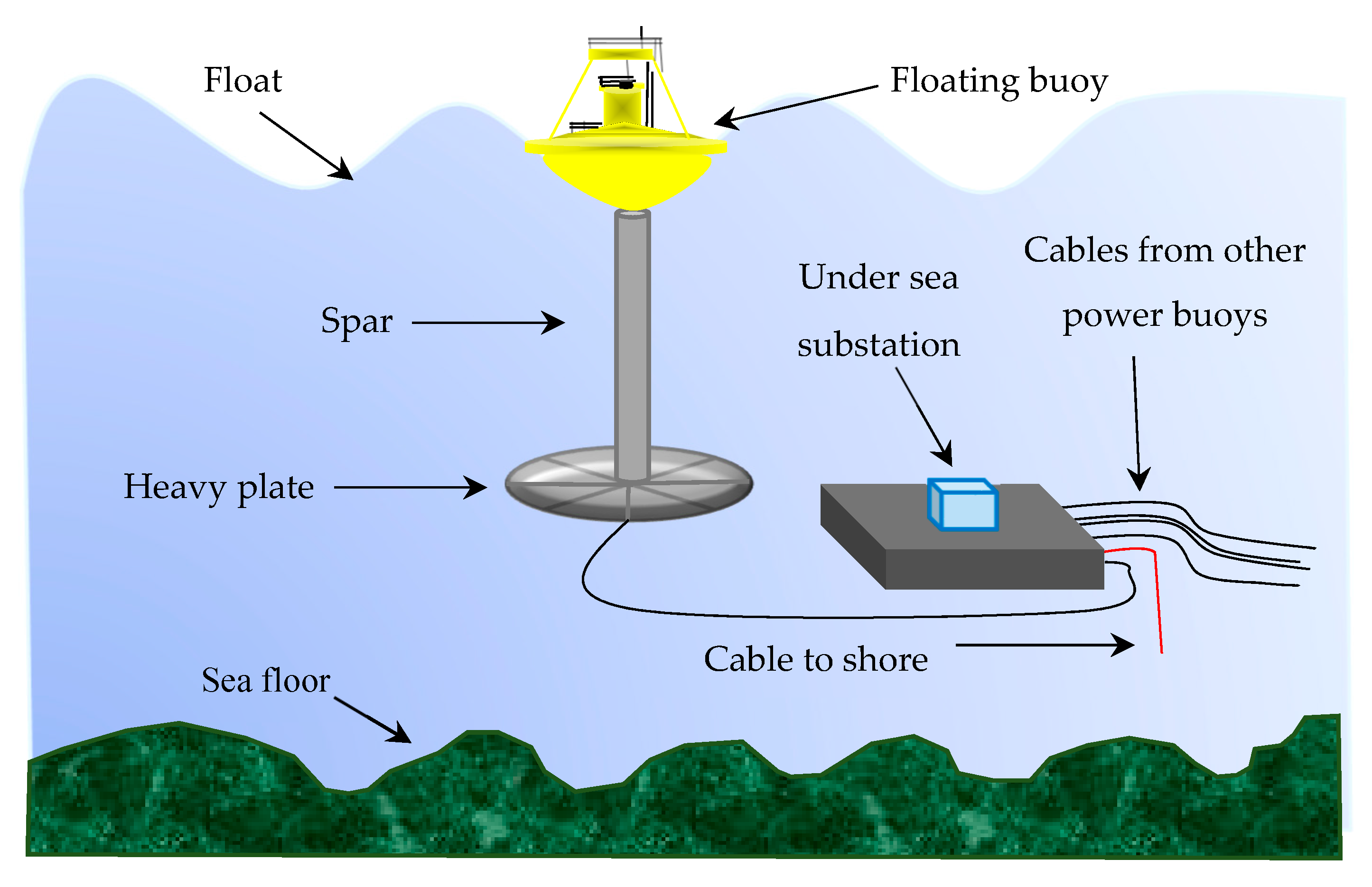
Wave energy converter (WEC) and wave energy device (WED) almost stand for each other. Usually, WED means a physical structure which mainly receives the mechanical power from the oceanic wave and drives it in a specific direction. This is because of facilitating electrical generators to produce electricity. On the other hand, WEC generally means a converter used in wave energy conversion system. Irregular mechanical energy obtained from the wave is first converted into regular mechanical motion. The motion could be rotational or linear/translational. Rotational motion usually drives a turbine, which further drives rotating electrical generator. On the other hand, translational motion drives a linear electrical generator. The WED is required to materialize the principle of wave energy conversion. In this section, some non-identical wave energy devices are discussed. WED is classified into many different types, which are based on operational concept such as oscillating water column. It could be on basis of location of the WED that can be situated nearshore or onshore, or based on vertical position it can be fixed, floating, or submerged, and the other point of view is orientation [14].
There are different types of WEDs, and it can be classified based on the site they are mounted. However, in most cases, there are three areas for which wave energy converters are represented, as shown in Figure 1 [44] where the average and exploitable amount are expressed in percentage of the maximum wave power. Onshore implies shoreline regions in which the water depth is 10–15 m and the maximum wave height has the ability to reach up to 7.8 m, as the wave trough would be about to touch the seabed [15]. Nearshore has intermediate water regions, and the water level can reach up to 15–25 m [15]. According to the water depth, it can be classified as deep water, intermediate water, and shallow water.
Offshore is in deep-water zone, and the water depth is higher than 50 m, and the wave height can reach up to 30 m or even more [15]. Wave power devices are less dense in onshore and nearshore areas than offshore as wave energy loses its power density when approaching the coastal area, as stated in Figure 1. Thus, building offshore devices are much easier than building onshore and nearshore devices. Because, it is very challenging to construct any large structure in the intermediate and shallow water regions due to violent wave breaking. In addition, these are the regions where the waves almost touch the sea bottom. The coastal structures could be more vulnerable to failure in intermediate and shallow water than that in deep water where calm sea is found, even though they are most likely nonlinear in nature.

3.1. Point Absorber

For the last three decades, wave power device has become a very important part for producing energy, and there are different types of wave power devices such as point absorber, overtopping or terminator device, oscillating water column, oscillating wave surge converter, submerge pressure differential, bulge wave converter. However, most researchers focus on the point absorber [23], which is cost effective and can produce adequate energy. It has moving parts where the horizontal dimension is less than the vertical one, which takes advantage of wave action at a single point, one part is almost motionless and the other part is mounted near the sea surface. It moves in a perpendicular motion, catching the wave energy which drives linear generator for producing electricity. There are different examples of point absorbers, but the well-known one is the Ocean Power Technology’s “Power Buoy”, as shown in Figure 2.

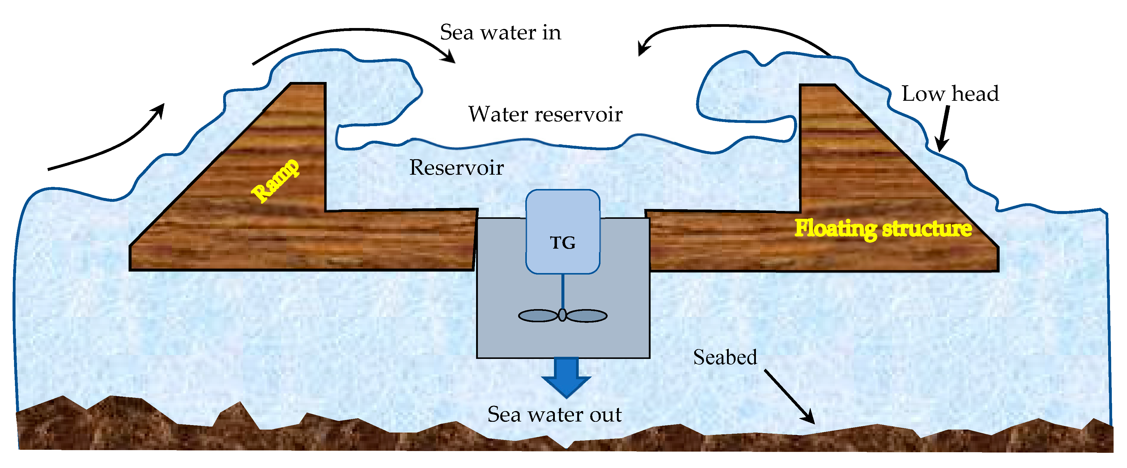
3.2. Overtopping Device

Overtopping wave power device (as shown in Figure 3) is also called terminator device, which has a huge structure that allows it to catch the sea water. When the wave reaches the channel, the water falls through the hole and passes through the turbine, which is connected to a rotating electrical generator. The turbine produces electrical energy from both potential energy and kinetic energy because potential energy is continuously converted to kinetic energy after a few moments. The familiar example of overtopping wave power device is Wave Dragon.

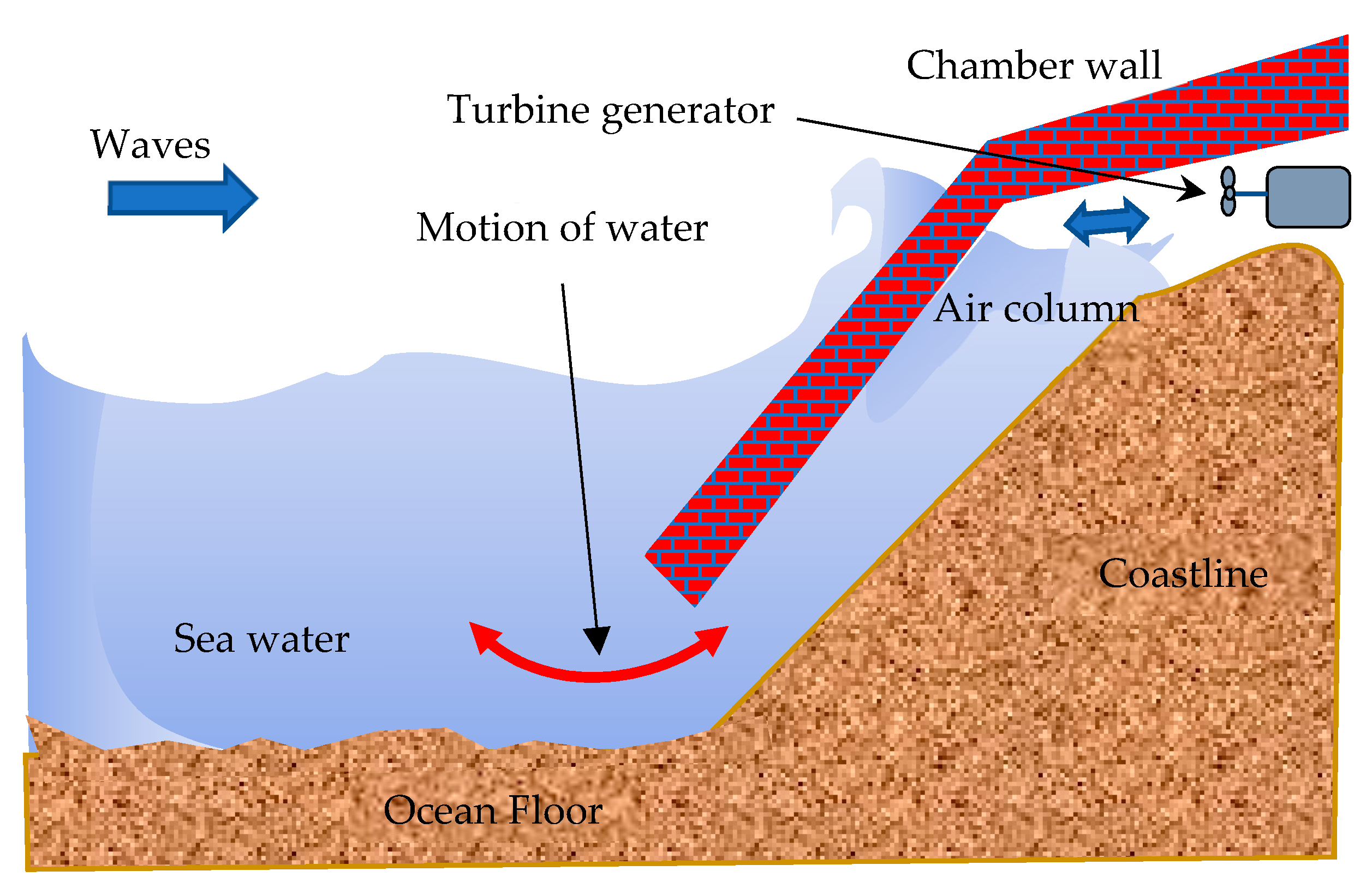
3.3. Oscillating Water Column

Oscillating water column (OWC) is a type of wave power device that produces electricity by utilizing the plentiful oceanic wave. It is built onto or near to the rocks and it is close to the sea bottom, as shown in Figure 4. The water is compressed and decompressed, and when the wave enters the chambers, the water level increases, and it creates high air pressure which drives the turbine. The air pressure inside the chamber under this condition is much greater than atmospheric pressure (14.7 psi). When the water falls back to the sea, the air pressure under this condition is much lower than atmospheric pressure. For this reason, air enters again into the chamber from outside, finding no other way. As a result, the air then flows in negative direction. It drives the turbine in such a way that it can produce electricity. An example of OWC is Wavegen Limpet.

3.4. Attenuators

Attenuator or surface attenuator wave power device is nearly identical to the direction of wave moves, which consists of connected sections including main tubes and bends that move when the wave hits serially to consecutive segments of this device one by one. Main tube includes nose tube mid tube, and end tube and inside the tubes where a power conversion module is placed in between two main tubes, as shown in Figure 5. The most used example of this type of WEC is Pelamis, manufactured by Pelamis Wave Power.
Hydraulic cylinder moves with the wave and pumps high pressure oil through hydraulic motors. Electricity is generated by electrical generator, which is driven by hydraulic motors.

3.5. Oscillating Wave Surge Converters

Oscillating wave surge converter is a type of WED that uses back and forth motion of ocean waves. The device is submerged in the bottom of the sea in deep water. The most common one is pendulum arm flap at the center of this device that makes the flap move, as shown in Figure 6, when the wave hits it. This movement pumps the water to a hydraulic power converter for driving generator to produce electricity. An example of this device is Wave Roller or Sea Oyster.

3.6. Submerged Pressure Differential
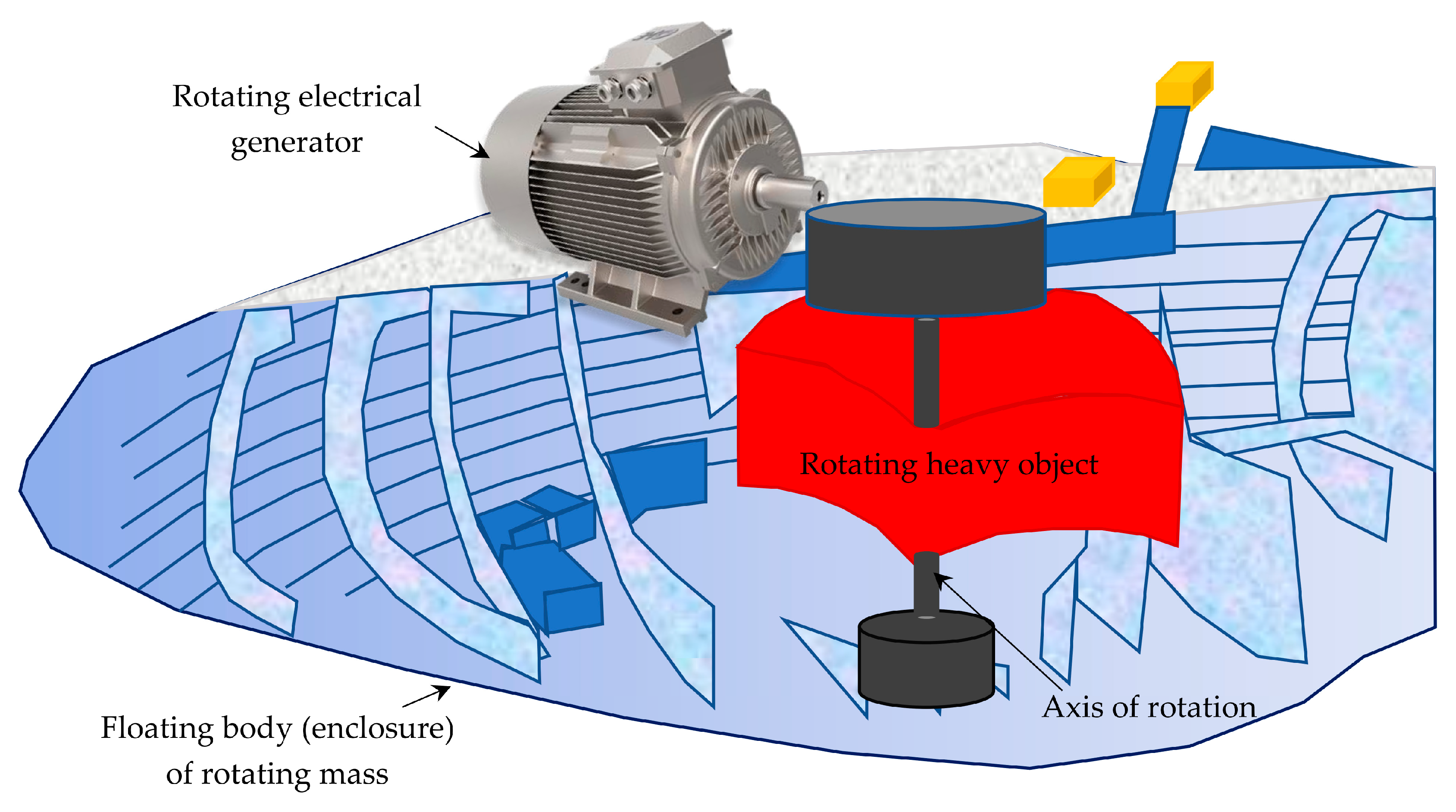
Submerged pressure differential devices as shown in Figure 7 are normally positioned at the lower level of the sea. When the wave moves, it makes the float move up and down overhead the device, creating alternating pressure that either pumps fluid through a system or drives a linear generator to produce electricity. The example of this type of wave energy converter is the Archimedes wave swing [42] which is suitable for generating electricity.

3.7. Rotating Mass

Rotating mass wave power device operates the motion of wave to roll a physical heavy object (mass) that produces mechanical energy. The rotating mass receives mechanical power from the oceanic wave and supplies it to the electrical generator, as shown in Figure 8. Few examples of rotating mass wave energy converter are Witt Energy, Wello: Penguin, Enorasy Labs: Robotic Juggler.

3.8. Bulge Head Wave Energy Converter

Bulge wave energy converter uses entirely new principles to convert oceanic wave energy into electrical power. This type of converter is also called Anaconda wave power device, as designed by Checkmate Sea Energy Ltd. It is used to generate electricity by using abandoned oceanic waves, as shown in Figure 9. It is made of elastic pipe, which is submerged just under the sea water surface at low pressure. One of the two sides of this elastic pipe is fixed and anchored with its head to the base. As the sea wave passes along the tube, a bulge wave is created, which moves in front of the wave. The energy is captured continuously, which is used to drive the turbine generator (TG) to produce electricity.

4. Challenges of Wave Energy Conversion

The problem that slows down the development of wave energy harvesting is high cost of the project and environmental challenge. Wave energy converter faces a number of technical issues, such as unbalanced frequency, which can be as low as 0.1 Hz, and it must be increased up to 50/60 Hz before supplying to the load/grid [45]. It also faces harsh marine environmental situations. These significant difficulties lessen the improvement of the devices, and it essentially requires quality operational material plan. Cyclone affects wave power level to increase up to 2000 kW/m, which is liable for uncertain condition, and it is also useless for production of electricity [38]. The reason that WEC cannot be developed quickly as other RESs is that the project cost is higher, and it can reach up to 22% of the total project cost [46]. Because of higher installation cost of the WEC, other RESs are more appealing than oceanic wave [47,48]. Wave energy has lower ecological effect compared to tidal energy, and there is uncertainty about cabling and marine life impact [47]. The rough sea atmosphere and sea saltiness makes adverse weather condition for WEC [49]. Oceanic WED is in the beginning stage/phase compared to other types of renewable energy devices such as photovoltaic cell or wind turbine generator [50]. Although various models are mentioned in different literatures, no convergence of wave conversion technology is guaranteed. Hence, it is hard to anticipate the challenges and address these at the beginning period of WEC. Recently, the most used wave energy device is Pelamis, and it has not yet reached the level of solar and wind energy in comparison of cost [51]. The construction and installation of WED is sophisticated and time consuming compared to the installed one [52]. Shoreline erosion would lessen because of energy production through WECs [53]. The main environmental impact of WECs may occur at the time of establishment period. Boring or digging up for the building of WED results in contamination or generates unbalance in the natural habitat of the ocean plants and animals [54]. Sea weather condition can be terrible because of natural disasters, which are very difficult to forecast, and the production of electricity could be irregular at this time. The power density relies on the wave amplitude and wave period that increases the challenges in the prediction of expected power production [52]. Another common difficulty is that, the electrical grid is far away from the place of WED, and there may be long transmission lines which increase the project cost. Oceanic WEC is developing day by day with different types of challenges. In offshore, wave motion is completely different than near shore, thus, it is not easy to forecast the way of the energy harvesting. To produce electricity, unbalanced wave is an additional obstacle [55]. When any of the machinery is damaged, it is a troublesome job to fix, and it creates difficulties [23]. The maintenance of the onshore device is relatively easier, but difficult to find appropriate position. The building of the offshore equipment is simple and the energy production in offshore is greater than onshore [56]. Another benefit of nearshore equipment is that they can be positioned on the ocean floor, but the existing electricity is very low compared to offshore devices. The construction and operation are inexpensive, but these must resist the tougher waves throughout the extreme conditions. Some engineers claim that offshore has the ability to offer good operation. Most of the energy is obtained in the surface because the rate of change in volume of water is massive that occurs in around one-quarter of a wavelength [23]. United Kingdom has improved in oceanic WED in comparison to other countries. Pelamis offshore device is used commercially, such as solar and wind energy devices. On the other hand, Wavegen, Limpet2, and other onshore equipment are working properly, but not widely used [56]. The challenge of efficiently capturing this irregular wave motion needs to be considered while designing the device. Both the device and its whole system need to be operated at the most common wave power levels to gain the maximum efficiency. Around 30–70 kW/m offshore waves are common in the British Isles and the Western Coasts of Europe [23]. Other challenges should be considered to mitigate the highly corrosive environment because of the operation on the water surface [57].
Although WEC is a renewable energy, a question is raised for the last three decades, which is the effect of WEC with comparison to other natural energy sources. Producing electricity in the ocean is environmentally friendly and there is no emission. WEC has environmental and social effects for building and operating in wave energy technology, where the impacts may be negative or positive. WEC projects have benefits and shortcomings, the production and gathering of WED could be one of the main causes of environmental effect, compared to other renewable energies. However, wave energy does not use any land area, which is advantageous with respect to other RESs. The operation of wave energy converter has effects on the marine animals and plant. It may have good impact on the economic development of the country [15].

5. Electrical Generators for WEC

In most of the cases, linear electrical generators are used in WEDs to produce electrical power directly from the oceanic wave, although rotational machines are also implemented. Typical linear and rotational electrical generators are depicted in the following.

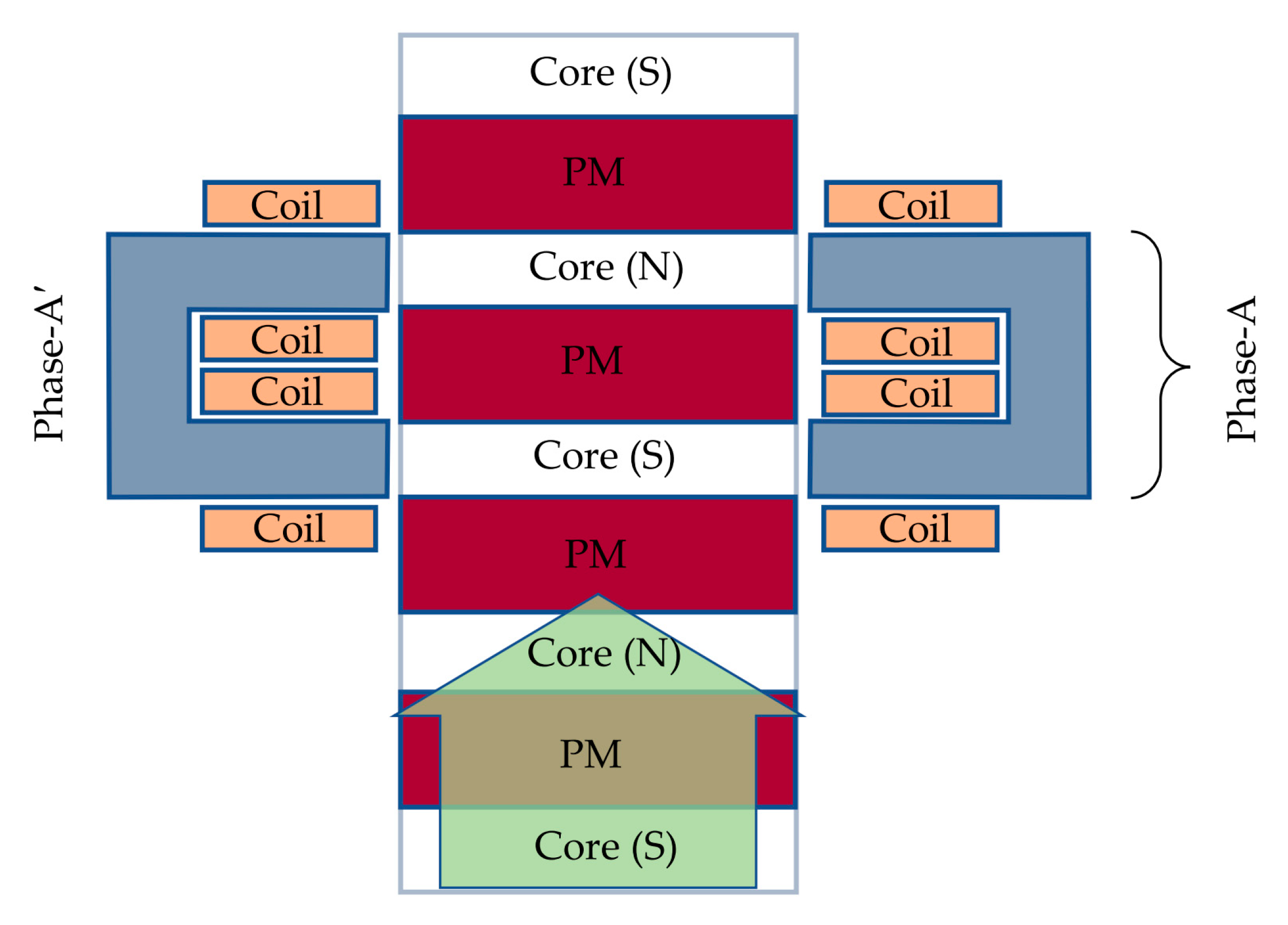
5.1. Linear Generator

At present, most electrical generators work with rotary motion, but linear generator works with translational motion. Permanent magnets are mostly used in linear generator to produce magnetic flux. Two main components of linear generator are translator and stator. When the ocean wave hits the floating buoy, the translator moves vertically where the direction can be upward or downward. For a specific time, the stator and the translator are adjusted, confronting each other, which is shown in Figure 10 and Figure 11. There is the North Pole (N) and the South Pole (S) of the permanent magnet located at the higher side and at the bottom side, respectively, of the stator (time t1). The change that happens in the direction for magnetic flux is caused by the dislocation of the stator. Figure 11 shows the location of the translator, which is shifted from the location as shown in Figure 10. In this consequence, S stands in the downside and N stands in the upside of the stator for time t2. Therefore, the way of magnetic flux in Figure 10 is reversed in the stator for moving translator location, which is shown in Figure 11 within the time interval t2t1. Therefore, the permanent magnet linear generator (PMLG) generates ac power because the direction of the induced voltage across the conductor changes with respect to time [58]. A typical PMLG is mounted in a WEC, which is illustrated in Figure 12.

5.2. Rotational Generator

Electricity can also be generated by mounting a rotational electrical generator with intermediate mechanical arrangement, as shown in Figure 13. When the wave hits sub-buoy, it moves upward and downward for which the belt-pulley moves in vertical direction and creates direct motion. It causes an opposite direction of rotation in the pump and gear box that is connected to the pulley. There are three valves, and two of these are check valves that permit the fluid to move in a particular direction. It goes through the pump inlet from the reservoir, and the shuttle valves work as a switch which connect the pump outlet to the inlet port of hydraulic motor. The motor constantly rotates in its given direction. Therefore, the generator converts energy all the time. Then electricity is produced, converted, and stored in the storage device [45].

6. Control Technologies

The most current state of the technologies for oceanic energy extraction include the types of WECs, electrical generators, control systems, installation sites of employed controller, characteristics of oceanic waves, power conversion methods, and the practical validation [59]. Progress of control systems for WECs employing various types of oceanic energy devices have become a high potential research interest in the OWE engineering [12,60]. Among different control methodologies, some of these are analyzed considering linear quadrature Gaussian design topology, reactive control, adjustable tuning, adaptive inertia, and latching control techniques [23].
A control technique is addressed in [50], which was designed to generate maximum electrical energy from OWE by controlling the reaction force of the PMLG [61]. A sensor-less control system is projected in [62] for transferring maximum electric power from generator to utility grid. It includes the feedback of linear displacement of slider and the measurement of electromotive force (EMF) using sensing coils. Maximum electric power extraction employing the direct drive WEDs with adjustable load criteria arises challenging issues [14,15]. These difficulties can be mitigated by controlling both the hardware and the software sections.
The difficulty of the control systems, sustainability, and finally the cost of the WEDs affect the utilization of maximum OWE [63]. Maximum OWE can be extracted from practical sea environment by using direct drive PMLG with sub-optimal control technology without the inevitability of forecasting of oceanic wave characteristics [64]. Control technologies that include method of reactive control, offer the usefulness of maximum OWE extraction [65]. With the target of OWE harvesting, a control concept is designed considering the vector control approach in [66] to control the electromotive force (EMF) of the PMLG.
A centralized model predictive control (MPC) methodology is developed in [67] for controlling the operation of WECs installed in an array configuration. The efficacy of the designed control system was found more robust compared to decentralized MPC and controller of restraining forces considering irregular as well as regular oceanic wave conditions. Another MPC system is proposed in [68] for especially a point absorber-based WED equipment integrating floating buoy configuration. It is employed for maximum OWE harvesting, considering some practical features such as the velocity and the wavering force of the power take off (PTO) system. A predictive current control concept is suggested in [69], which is more precise to the inaccuracies of estimated inductance of load. This method also diminishes the unsteady effect at zero current [70,71] and very low EMF conditions.
A damping force control technique is designed and practically verified in [72] considering the heaving motion of the float and very swift operation of the WEC. An advanced resonance control algorithm for an Archimedes wave swing based WEC is designed in [62] combining both the stiffness force and the damping force of the PTO. In order to ensure a sustained decoupling voltage across the capacitor, an accurately designed voltage controller is also addressed in detail. The efficacy and the operation of the WECs are influenced by the control methodology that controls the dynamic action of the PTO [73]. With the target of obtaining developed adeptness of the WEDs, various predictive control methods are designed that include the copper loss during the optimization process of WECs [74]. On the contrary, latching control method, which is the substitute concept of reactive control, lessens the losses of electrical generator by regulating the flow of energy in one direction [75]. Practical employment of such latching control technology involves forecasting of information relating the oceanic wave properties to regulate freeing of the floats [76]. The proficiency in both the latching and reactive control technique can be improved by considering the restrictions on the excursion of WECs under irregular wave characteristics during scheming of the control system [77]. Voltage unbalanced issues may be created because of the direct incorporation of the distributed renewable sources to the utility service [78].

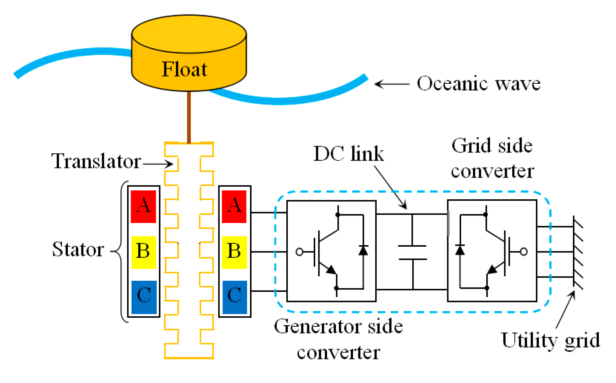
6.1. Direct Drive Linear Generator

Electrical power generation employing WEC and grid integration configuration including control systems are depicted in Figure 14 [79].
The WED is designed using floating body structures and a direct drive PTO unit. The float produces linear motion following the oceanic wave oscillation, and the PTO is nothing but a system how it receives power from the oceanic wave. The generated voltage is connected to a converter known as generator side power converter. The main parts of the PMLG are the linearly sliding translator and the static stator that usually consists of a coil of wires. Due to the relative linear motion between the stator windings and slider, in existence of magnetic field, voltage is generated in the stator windings. Because of oscillating oceanic waves, the translator causes a variable relative velocity with respect to the stator. As a result, the induced ac voltage does not have steady amplitude and frequency. After multi-stage (AC–DC–AC) power conversion, the grid synchronization is ensured.

6.2. Combined Rotational and Linear Generator

The SEAREV is an advanced fully combined WED, which is basically a floating unit. LHEEA laboratory develops SEAREV, which is located at Ecole Centrale de Nantes [80]. It mainly consists of a wheel with horizontal rotating axis, which is fenced by a floating structure. The grid synchronization technology of various oceanic WEDs with multistage control configuration is illustrated in Figure 15 [81].
OWC and heaving buoy employ PMLG to produce electrical energy from OWE. As SEAREV incorporates rotational electrical generator to generate electric power, the generated power is converted from AC–DC by the grid side converter, and again reverse action is controlled by the load side power converter. Flux weakening control-based system uses the floating speed of float as input and provides pulse width modulated control signals for the converter operation. The WEC associates the rotational PMLG to generate electricity. Several testing equipment are designed for laboratory test purposes. In most of the testing devices, a linear motion is produced by a crank shaft coupled to a rotating structure.

6.3. LIMPET WED

LIMPET is the only device which is found in onshore and follows OWC principle. The LIMPET has enclosed chamber that has an opening underneath the seabed. With the incident of oceanic wave, the water enters the chamber, and the water level inside the chamber increases. When the sea water returns back, the water level decreases. Therefore, variation in the air pressure is created, and the air moves forward and backward through the turbine. Air is compressed and decompressed that has enough capability to drive the turbine [82]. It is driven in a similar direction for both forward and reverse air flow through the turbine, and the turbine drives the electrical generator. The generated electrical power can be supplied to the load or grid. The process of producing and transferring power from wave to the grid is shown in Figure 16.

6.4. Wave Dragon WED

Wave Dragon [33] was successfully developed in Denmark in 2003. When wave approaches to the rig, two wave reflectors guide the water to the reservoir to store in a tank, then the water flows through the turbine. The equipment [83] used to produce electricity from Wave Dragon is shown in Figure 17. Wave Dragon has the ability to withstand environmental hazards. The device is designed to be large and heavy to support any rolling and pitching. The low flooding in heavy design allows giant wind waves to simply pass over the rig.

6.5. Direct Drive WEC

Figure 18 shows a direct drive permanent magnet synchronous generator used in a WEC [83]. Pitch angle is used to control power generation from generator. It has a sensor to control pitch angle. The shaft position is fixed to control the supplied electrical power from the generator. Since oceanic wave parameter is not constant, any type of load is not directly connected to the linear generator. Some additional arrangements are required such as voltage source controllers VSC1 and VSC2. The magnitude and frequency of oceanic wave are unknown. For this reason, it is not possible to control the power or energy from the oceanic wave. If permanent magnet synchronous generator is used, it would produce variable frequency, which is harmful for the load. Using this type of power, it is not possible to drive any commercial load. By using these types of arrangements, it is easy to drive any type of load by controlling the transistors. VSC1 is used as a converter, which converts AC power to DC power. Filter is used to minimize the ripple. The second one, VSC2, inverts DC power to AC power. Then it is connected to the grid. To control the transistor, on the bottom part of the VSC there are two arrows which indicate it is essential to use controller to produce a specific amount of voltage.

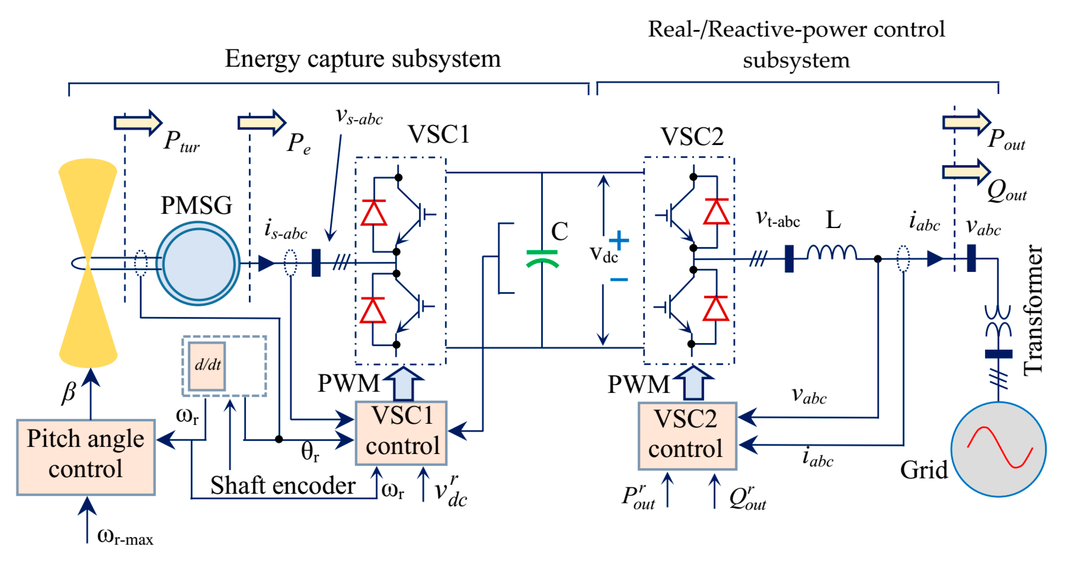
6.6. The Energy Capture Sub-system

This is simpler transfer function controller circuit considering input and output where the whole part is transfer function. There are some plucks like limiter and some feedbacks. Figure 19 demonstrates a control block diagram of energy harnessing system. The purpose is to control the dc link voltage v dc , where v w is the wave speed and p o u t is the output power which causes disruption in the control system. The DC-link voltage compensator C i ( s ) is pretended to be of the proportional integral (PI) form. The permanent magnet synchronous linear generator is controlled by voltage source controller VSC1 (Figure 19), such that torque T e tracks the set point T e r , as determined by passing the output of C i ( s ) [67]. Figure 19 also shows that the pitch angle is controlled to make sure that the PMLG speed does not exceed the highest value, w r max [84]. The pitch angle compensator C p ( s ) is also determined as the PI form. The output of PI compensator is passed inside the limiter and it characterizes pitch angle β, which can be changed at any time.

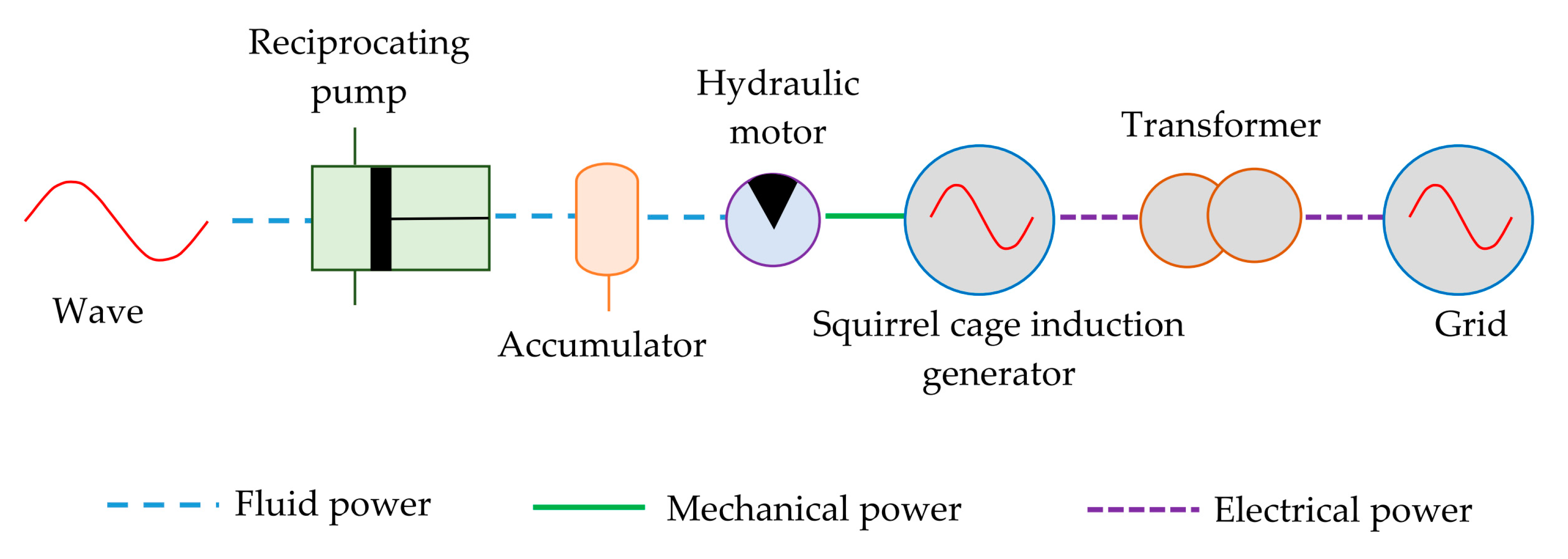
6.7. Hydraulic System

Hydraulic system has effective energy conversion system. It involves two steps to convert the power. First stage is a floating body that is designed to catch the mechanical energy produced by the wave motion, which then converts hydraulic energy by using compression unit system [85]. The second part is a generator that produces electrical energy. The electrical production system starting from oceanic wave to the grid is explained in Figure 20.

7. Piezoelectric Materials Based OWEC

The structural configuration of the piezoelectric crystal, such as crystal film, is incorporated with single crystals and exhibits the intrinsic energy conversion properties. In case of ceramic type piezoelectric devices, such as barium titanate (BaTiO3) and AlN, sufficient small-scale quartzes are randomly oriented under the application of electric potential that exhibit piezoelectric features. Research discloses that electrical power production is possible by implementing the piezoelectric effects as utilized on different devices such as microphones, load cells, etc. The power harvester designed with piezoelectric materials is constructed with the excellent characteristics of greater energy density, simple in design construction, and reasonable maintenance cost. It also has the ability of operating as an energy transducer and covers versatile application areas. Electrical energy extracting devices can be designed from micro and nano-scaled flexible piezoelectric materials [76] easily. Piezoelectric materials are being attracted by the researchers to extract the kinetic energy from the OWE and to generate electrical energy. It is promising to produce micro-watt power scale electricity from 0.5 m/s oceanic wave velocity [86].
A newly designed piezoelectric material-based wave energy harvester is projected in [87], which is coupled to a floating structure and experimentally validated for maximum 169 V output voltage at no load condition (100 MΩ). Utilization of piezoelectric devices as the OWE harvester may mitigate the complexities relating to the power production such as discontinuity and reduced land area for enough energy extraction using traditional WEDs. An improved WED incorporating a piezoelectric sensor is designed and experimentally verified for 12.35 mW output power at 20 Hz functioning frequency [88]. Piezoelectric material-based energy generators offer higher conversion efficiency, and it is analyzed that large scale power generation (kW range) from wind and oceanic energy is under both the research work and prototype development [89]. Well-designed piezoelectric OWCs include the piezoelectric floats and cantilevered beams [90]. In [91], theoretical as well as practical studies are conducted for the development of piezoelectric materials-based energy harvesters. A piezoelectric WED with floating and sinking arrangement in [92] is illustrated in Figure 21, where FPED is oscillating, for which electricity is generated [93].
The energy transducer is made of a semi-submerged type structure, which can vibrate according to the dynamic oscillation of the oceanic waves. The bottom part (plate) of this device is anchored, and the upper plate is connected with semi-submerged plate. Due to incident of wave, upper plate would shake, which further makes the flexible piezoelectric device oscillating. The cantilever plates are attached to the semi-submerged member and the regular forming and deforming of the piezoelectric device occurs when force of water flow is exerted. Voltage is induced by transforming the stress applied to the transducer by utilizing the characteristics of the piezoelectric material. Generation of electrical energy using piezoelectric energy harvesters needs future research work for further development. A reliable numerical model is explained in [94], which uses computational fluid dynamics of oceanic wave energy systems.

8. Conclusions

Wave energy is a clean source of renewable energy. At present, many countries around the globe are actively developing techniques to produce electricity from ocean energy. For sustainable development in the sector of renewable energy, advances of wave energy conversion technology are needful. In this paper, the possibilities along with the developments of the exceedingly promising OWE conversion systems are focused. Various electrical power generation methods are discussed and the relative comparisons are outlined. Among these, point absorber type direct drive WEDs are found promising for its outstanding aspects. Literature reviews show that linear generators are more suitable for direct drive power generation, but the generated power is low because of its low relative velocity between the stator and the translator. On the contrary, rotary generators can be implemented, but it requires other auxiliary devices, which makes the whole system complex. It is expected to obtain high power by employing high graded materials in the linear generator with better control strategy. Moreover, proper controller ensures better output power at different cases and sea wave conditions. In addition, different types of piezoelectric device based WEDs are introduced with their arrangements for harvesting OWE. The direct-drive WEC, the energy capture sub-system, and hydraulic system equipment utilized in a hydraulic system are needed to collaborate for generating electrical energy from the ocean successfully. Block diagram of these systems are therefore illustrated with detail explanation.

Author Contributions

Conceptualization, O.F.; resources, O.F., K.A. and M.R.K.; drafting, A.D.T. and M.M.F.; organization and presentation, O.F. and M.R.I. All authors have read and agreed to the published version of the manuscript.

Funding

This research received no external funding.

Conflicts of Interest

The authors declare no conflict of interest.

References

  1. Shakouri, G.H. The share of cooling electricity in global warming: Estimation of the loop gain for the positive feedback. Sci. Direct 2019, 79, 747–761. [Google Scholar] [CrossRef]
  2. National Research Council (NRC). Advancing the Science of Climate Change; The National Academies Press: Washington, DC, USA, 2010.
  3. Farrok, O.; Islam, M.R.; Sheikh, M.R.I.; Guo, Y.G.; Zhu, J.G. Design and Analysis of a Novel Lightweight Translator Permanent Magnet Linear Generator for Oceanic Wave Energy Conversion. IEEE Trans. Magn. 2017, 53, 1–4. [Google Scholar] [CrossRef] [Green Version]
  4. Bashir, M.S.; Farrok, O. Yttrium Barium Copper Oxide Superconductor Used in a Linear Generator for High Power Generation from the Oceanic Wave. In Proceedings of the 2019 International Conference on Electrical, Computer and Communication Engineering (ECCE), Cox’s Bazar, Bangladesh, 7–9 February 2019; pp. 1–5. [Google Scholar]
  5. Pisani, C.; Villacci, D.; Carlini, E.M.; Lauria, D. An integrated approach to improve the networks security in presence of high penetration of RES. In Proceedings of the 2014 International Symposium on Power Electronics, Electrical Drives, Automation and Motion (SPEEDAM), Ischia, Italy, 20–22 June 2014. [Google Scholar]
  6. Farah, M.M.; Farrok, O.; Ahmed, K. Kool Mµ Powder Core Used in a Flux Switching Linear Electrical Machine for Electricity Generation from the Oceanic Wave. In Proceedings of the 2019 IEEE International Conference on Power, Electrical, Electronics and Industrial Applications (PEEIACON), Dhaka, Bangladesh, 29 November–1 December 2019. [Google Scholar]
  7. Zhu, S.; Zhang, Y.; Chowdhury, A.A. Capacity credit of wind generation based on minimum resource adequacy procurement. IEEE Trans. Ind. Appl. 2012, 48, 730–735. [Google Scholar] [CrossRef]
  8. Farrok, O.; Islam, M.R.; Islam Sheikh, M.R.; Guo, Y.; Zhu, J.; Lei, G. Oceanic Wave Energy Conversion by a Novel Permanent Magnet Linear Generator Capable of Preventing Demagnetization. IEEE Trans. Ind. Appl. 2018, 54, 6005–6014. [Google Scholar] [CrossRef]
  9. Dugan, R.C.; Taylor, J.A.; Montenegro, D. Energy storage modeling for distribution planning. IEEE Trans. Ind. Appl. 2017, 53, 954–962. [Google Scholar] [CrossRef]
  10. Molla, S.; Farrok, O.; Islam, M.R.; Muttaqi, K.M. Analysis and design of a high performance linear generator with high grade magnetic cores and high temperature superconducting coils for oceanic wave energy conversion. IEEE Trans. Appl. Supercond. 2019, 29, 5201105. [Google Scholar] [CrossRef]
  11. Mueller, M.A. Electrical generators for direct drive wave energy converters. IEEE Proc. Gener. Transm. Distrib. 2002, 149, 446–456. [Google Scholar] [CrossRef]
  12. Clément, A.; McCullen, P.; Falcão, A.; Fiorentino, A.; Gardner, F.; Hammarlund, K.; Lemonis, G.; Lewis, T.; Nielsen, K.; Petroncini, S.; et al. Wave energy in Europe: Current status and perspectives. Renew. Sustain. Energy Rev. 2002, 6, 405–431. [Google Scholar] [CrossRef]
  13. Baker, N.J.; Mueller, M.A.; Brooking, P.R.M. Electrical power conversion in direct drive wave energy converters. In Proceedings of the European Wave Energy Conference, Cork, Ireland, 17–20 September 2003; pp. 197–204. [Google Scholar]
  14. Hals, J.; Falnes, J.; Moan, T. A Comparison of selected strategies for adaptive control of wave energy converters. J. Offshore Mech. Arct. Eng. 2011, 133, 031101. [Google Scholar] [CrossRef]
  15. Tom, N.; Yeung, R.W. Experimental Confirmation of Nonlinear-Model-Predictive Control Applied Offline to a Permanent Magnet Linear Generator for Ocean-Wave Energy Conversion. IEEE J. Ocean. Eng. 2016, 41, 281–295. [Google Scholar]
  16. Oceans of energy: European Ocean Energy Roadmap 2010–2050; European Ocean Energy Association; Imprimerie Bietlot: Charleroi, Belgium, 2010.
  17. Pelc, R.; Fujita, R.M. Renewable energy from the ocean. Mar. Policy 2002, 26, 471–479. [Google Scholar] [CrossRef]
  18. Rahm, M.; Bostrom, C.; Svensson, O.; Grabbe, M.; Bülow, F.; Leijon, M. Offshore underwater substation for wave energy converter arrays. IET Renew. Power Gener. 2010, 4, 602–612. [Google Scholar] [CrossRef]
  19. Xie, J.; Zuo, L. Dynamics and control of ocean wave energy converters. Int. J. Dyn. Control 2013, 1, 262–276. [Google Scholar] [CrossRef] [Green Version]
  20. Prudell, J.; Stoddard, M.; Amon, E.; Brekken, T.K.A.; von Jouanne, A. A permanent-magnet tubular linear generator for ocean wave energy conversion. IEEE Trans. Ind. Appl. 2010, 46, 2392–2400. [Google Scholar] [CrossRef]
  21. Zhang, H.; Nie, Z.; Xiao, X.; Aggarwal, R.; Kang, Q.; Ainslie, M.; Zhu, J.; Coombs, T.; Yuan, W. Design and simulation of SMES system using YBCO tapes for direct drive wave energy converters. IEEE Trans. Appl. Supercond. 2013, 23, 5700704. [Google Scholar] [CrossRef] [Green Version]
  22. Bianchi, N.; Bolognani, S.; Corte, D.D.; Tonel, F. Tubular linear permanent magnet motors: An overall comparison. IEEE Trans. Ind. Appl. 2003, 39, 466–475. [Google Scholar] [CrossRef]
  23. Truong, D.Q.; Ahn, K.K. Development of a novel point absorber in heave for wave energy conversion. Renew. Energy 2014, 65, 183–191. [Google Scholar] [CrossRef]
  24. Drew, B.; Plummer, A.R.; Sahinkaya, M.N. A review of wave energy converter technology. Proc. Inst. Mech. Eng. Part A J. Power Energy 2009, 223, 887–902. [Google Scholar] [CrossRef] [Green Version]
  25. Mapping and Assessment of the United States Ocean Wave Energy Resource; Electric Power Research Institute (EPRI): Palo Alto, CA, USA, 2011.
  26. Zhang, D.; Li, W.; Lin, Y. Wave energy in China: current status and perspectives. Renew. Energy 2009, 34, 2089–2092. [Google Scholar] [CrossRef]
  27. Rodrigues, L. Wave power conversion systems for electrical energy production. Renew. Energ. Power Qual. J. 2008, 1, 601–607. [Google Scholar] [CrossRef] [Green Version]
  28. Muetze, A.; Vining, J.G. Ocean wave energy conversion—A survey. In Proceedings of the 2006 IEEE Industry Applied Conference Forty-First IAS Annual Meeting, Tampa, FL, USA, 8–12 October 2006; pp. 1410–1417. [Google Scholar]
  29. U.S. Marine and Hydrokinetic Renewable Energy Roadmap. Ocean Renewable Energy Coalition, USA, 2011. Available online: http://www.policyandinnovationedinburgh.org/uploads/3/1/4/1/31417803/mhk-roadmap-executive-summary-final-november-2011.pdf (accessed on 11 March 2020).
  30. Ocean Power Technologies. Available online: http://www.oceanpower (accessed on 8 September 2019).
  31. Wavebob. Available online: http://www.wavebob.com/home/ (accessed on 8 September 2019).
  32. Wavestar. Available online: http://www.wavestarenergy.com/ (accessed on 8 September 2019).
  33. Wave Dragon. Available online: http://www.wavedragon.net/ (accessed on 8 September 2019).
  34. Yang, X.; Song, Y.; Wang, G.; Wang, W. A comprehensive review on the development of sustainable energy strategy and implementation in China. IEEE Trans. Sustain. Energy 2010, 1, 57–65. [Google Scholar] [CrossRef]
  35. Wave Energy: 2007 Survey of Energy Resources; World Energy Council: London, UK, 2007.
  36. Vermaak, R.; Kamper, M.J. Design aspects of a novel topology air-cored permanent magnet linear generator for direct drive wave energy Converters. IEEE Trans. Ind. Electron. 2012, 59, 2104–2115. [Google Scholar] [CrossRef]
  37. Bhattacharyya, R.; McCormick, M.E. Wave Energy Conversion, 1st ed.; Elsevier Science: Amsterdam, The Netherlands, 2003. [Google Scholar]
  38. Czech, B.; Bauer, P. Wave energy converter concepts: Design challenges and classification. IEEE Ind. Electron. Mag. 2012, 6, 4–16. [Google Scholar] [CrossRef]
  39. Ross, D. Power from the Waves; Oxford University Press: Oxford, UK, 1995. [Google Scholar]
  40. Aliprantis, D.; Sharkawi, M.E.; Muljadi, E.; Brown, I.; Chiba, A.; Dorrell, D.; Erlich, I.; Kerszenbaum, I.; Levi, E.; Mayor, K.; et al. Guest editorial electric machines in renewable energy applications. IEEE Trans. Energy Convers. 2015, 30, 1609–1610. [Google Scholar] [CrossRef]
  41. Wu, F.; Ju, P.; Zhang, X.P.; Qin, C.; Peng, G.J.; Huang, H.; Fang, J. Modeling, control strategy, and power conditioning for direct-drive wave energy conversion to operate with power grid. Proc. IEEE 2013, 101, 925–941. [Google Scholar] [CrossRef]
  42. Guanche, R.; Go´mez, V.; Vidal, C.; Eguinoa, I. Numerical analysis and performance optimization of a submerged wave energy point absorber. Ocean Eng. 2013, 59, 214–230. [Google Scholar] [CrossRef]
  43. Pan, J.F.; Zou, Y.; Cheung, N.; Cao, G. On the voltage ripple reduction control of the linear switched reluctance generator for wave energy utilization. IEEE Trans. Power Electron. 2014, 29, 5298–5307. [Google Scholar] [CrossRef]
  44. Ran, L.; Mueller, M.A.; Ng, C.; Tavner, P.J.; Zhao, H.; Baker, N.J.; McDonald, S.; McKeever, P. Power conversion and control for a linear direct drive permanent magnet generator for wave energy. IET Renew. Power Gener. 2011, 5, 1–9. [Google Scholar] [CrossRef]
  45. Liu, C.; Yu, H.; Hu, M.; Liu, Q.; Zhou, S.; Huang, L. Research on a permanent magnet tubular linear generator for direct drive wave energy conversion. IET Renew. Power Gener. 2014, 8, 281–288. [Google Scholar] [CrossRef]
  46. Doyle, S.; Aggidis, G.A. Development of multi-oscillating water columns as wave energy converter. Renew. Sustain. Energy Rev. 2019, 107, 75–86. [Google Scholar] [CrossRef] [Green Version]
  47. Chenari, B.; Saadatian, S.S.; Ferreira, A. Wave energy systems: An overview of different wave energy converters and recommendation for future improvements. In Proceedings of the 8th International Technology, Education Development Conference, Valencia, Spain, 10–12 March 2014. [Google Scholar]
  48. Farrok, O.; Islam, M.R.; Sheikh, M.R.I. Analysis of the oceanic wave dynamics for generation of electrical energy using a linear generator. J. Energy 2016, 2016, 3437027. [Google Scholar] [CrossRef] [Green Version]
  49. Consultants 1981 Aassessment. Consulting Engineers Rendel Palmer & Tritton; Consulting Engineers Rendel Palmer & Tritton: London, UK, 1982.
  50. Wave Energy Technology Brief. Available online: http://irena.org/documentdownloads/publications/wave-energy_v4_web.pdf (accessed on 8 September 2019).
  51. Astariz, S.; Iglesias, G. The economics of wave energy: A review. Renew. Sustain. Energy Rev. 2015, 45, 397–408. [Google Scholar] [CrossRef]
  52. Bahaj, A.S. Generating electricity from the oceans. Renew. Sustain. Energy Rev. 2011, 15, 3399–3416. [Google Scholar] [CrossRef]
  53. Mueller, M.; Jeffrey, H. UKERC Marine (Wave and Tidal Current) Renewable Energy Technology Roadmap: Summary Report; UK Energy Research Centre, University of Edinburgh: Edinburgh, UK, 2008. [Google Scholar]
  54. Guanche, R.; Andres, A.D.; Simal, P.D.; Vidal, C.; Losada, I.J. Uncertainty analysis of wave energy farms financial indicators. Renew. Energy 2014, 68, 570–580. [Google Scholar] [CrossRef]
  55. Aderinto, T.; Li, H. Ocean wave energy converters: Status and challenges. Energies 2018, 11, 1250. [Google Scholar] [CrossRef] [Green Version]
  56. Starling, M. Guidelines for Reliability, Maintainability and Survivability of Marine Energy Conversion Systems: Marine Renewable Energy Guides; European Marine Energy Centre: Orkney, UK, 2009. [Google Scholar]
  57. Mustapa, M.A.; Yaakob, O.B.; Ahmed, Y.M.; Rheem, C.-K.; Koh, K.K.; Adnan, F.A. Wave energy device and breakwater integration: A review. Renew. Sustain. Energy Rev. 2017, 77, 43–58. [Google Scholar] [CrossRef]
  58. Inger, R.; Attrill, M.J.; Bearhop, S.; Broderick, A.C.; Grecian, W.J.; Hodgson, D.J.; Mills, C.; Sheehan, E.; Votier, S.C.; Witt, M.J.; et al. Marine renewable energy: Potential benefits to biodiversity? An urgent call for research. J. Appl. Ecol. 2009, 46, 1145–1153. [Google Scholar] [CrossRef]
  59. Ilyas, A.; Kashif, S.A.R.; Saqib, M.A.; Asad, M.M. Wave electrical energy systems: Implementation, challenges and environmental issues. Renew. Sustain. Energy Rev. 2014, 40, 260–268. [Google Scholar] [CrossRef]
  60. Falnes, J.; Lovseth, J. Ocean wave energy. Energy Policy 1991, 19, 768–775. [Google Scholar] [CrossRef]
  61. Ozkop, E.; Altas, I.H. Control, power and electrical components in wave energy conversion systems: A review of the technologies. Renew. Sustain. Energy Rev. 2017, 67, 106–115. [Google Scholar] [CrossRef]
  62. Yavuz, H.; Stallard, T.J.; McCabe, A.P.; Aggidis, G.A. Time series analysis-based adaptive tuning techniques for a heaving wave energy converter in irregular seas. J. Power Energy 2007, 221, 77–90. [Google Scholar] [CrossRef]
  63. Wu, F.; Zhang, X.P.; Ju, P.; Sterling, M.J.H. Optimal control for AWS-based wave energy conversion system. IEEE Trans. Power Syst. 2009, 24, 1747–1755. [Google Scholar]
  64. Vermaak, R.; Kamper, M.J. Experimental evaluation and predictive control of an air-cored linear generator for direct-drive wave-energy converters. IEEE Trans. Ind. Appl. 2012, 48, 1817–1826. [Google Scholar] [CrossRef]
  65. Shek, J.K.H.; Macpherson, D.E.; Mueller, M.A.; Xiang, J. Reaction force control of a linear electrical generator for direct drive wave energy conversion. IET Renew. Power Gener. 2007, 1, 17–24. [Google Scholar] [CrossRef] [Green Version]
  66. Vermaak, R.; Kamper, M.J. Construction and control of an air-cored permanent magnet linear generator for direct drive wave energy converters. In Proceedings of the IEMDC, Niagara Falls, ON, Canada, 15–18 May 2011; pp. 1076–1081. [Google Scholar]
  67. Ekström, R.; Ekergård, B.; Leijon, M. Electrical damping of linear generators for wave energy converters—A review. Renew. Sustain. Energy Rev. 2015, 42, 116–128. [Google Scholar] [CrossRef]
  68. Li, B.; Macpherson, D.E.; Shek, J.K.H. Direct drive wave energy converter control in irregular waves. In Proceedings of the IET Conference Renewable Power Generation, Edinburgh, UK, 6–8 September 2011; pp. 1–6. [Google Scholar]
  69. Falnes, J. Ocean Waves and Oscillating Systems. Linear Interactions including Wave-Energy Extraction; Cambridge University Press: Cambridge, UK, 2004. [Google Scholar]
  70. Yang, J.; Huang, L.; Hu, M.; Jiu, C.; Zhao, D. Research on a control strategy of the flux switching permanent magnet linear generator for wave energy extraction. In Proceedings of the 18th International Conference on Electrical Machines and Systems, Pattaya, Thailand, 25–28 October 2015; pp. 1666–1670. [Google Scholar]
  71. Oetinger, D.; Magaña, M.E.; Sawodny, O. Centralised model predictive controller design for wave energy converter arrays. IET Renew. Power Gener. 2015, 9, 142–153. [Google Scholar] [CrossRef]
  72. Richter, M.; Magaña, M.E.; Sawodny, O.; Brekken, T.K.A. Power optimization of a point absorber wave energy converter by means of linear model predictive control. IET Renew. Power Gener. 2014, 8, 203–215. [Google Scholar] [CrossRef]
  73. Bode, G.H.; Loh, P.C.; Newman, M.J.; Holmes, D.G. An improved robust predictive current regulation algorithm. IEEE Trans. Ind. Appl. 2005, 41, 1720–1733. [Google Scholar] [CrossRef]
  74. Summers, T.; Betz, R.E. Dead-time issues in predictive current control. IEEE Trans. Ind. Appl. 2004, 40, 835–844. [Google Scholar] [CrossRef]
  75. Murai, Y.; Riyanto, A.; Nakamura, H.; Matsui, K. PWM strategy for high frequency carrier inverters eliminating current clamps during switching deadtime. In Proceedings of the IEEE Industry Applications Society (IAS) Annual Meeting, Houston, TX, USA, 4–9 October 1992; pp. 317–322. [Google Scholar]
  76. Hong, Y.; Waters, R.; Boström, C.; Eriksson, M.; Engström, J.; Leijon, M. Review on electrical control strategies for wave energy converting systems. Renew. Sustain. Energy Rev. 2014, 31, 329–342. [Google Scholar] [CrossRef]
  77. de la Villa-Ja´en, A.; Garc´ıa Santana, A.; Montoya, D. Maximizing output power of linear generator for wave energy conversion. Int. Trans. Electr. Energy Syst. 2014, 24, 875–890. [Google Scholar] [CrossRef]
  78. Montoya, A.D.E.; de la Villa-Ja´en, A.; Garc´ıa Santana, A. Considering linear generator copper losses on model predictive control for a point absorber wave energy converter. Energy Convers. Manag. 2014, 78, 173–183. [Google Scholar] [CrossRef]
  79. Budal, K.; Falnes, J. Interacting point absorbers with controlled motion. In Power from Sea Waves; Count, B., Ed.; Academic: London, UK, 1980; pp. 38–399. [Google Scholar]
  80. Fusco, F.; Ringwood, J. Short-term wave forecasting for real-time control of wave energy converters. IEEE Trans. Sustain. Energy 2010, 1, 99–106. [Google Scholar] [CrossRef] [Green Version]
  81. Montoya, A.D.E.; de la Villa Ja´en, A.; Garc´ıa Santana, A. Improvements in the reactive control and latching control strategies under maximum excursion constraints using short-time forecast. IEEE Trans. Sustain. Energy 2016, 7, 427–435. [Google Scholar] [CrossRef]
  82. Xiao, X.; Huang, X.; Kang, Q. A hill-climbing-method-based maximum-power-point-tracking strategy for direct-drive wave energy converters. IEEE Trans. Ind. Electron. 2016, 63, 257–267. [Google Scholar] [CrossRef]
  83. Clémot, H.; Robin, F.D.; Babarit, A.; Tran, T.Q. A wave-to-wire chain modeling and command for a direct drive wave energy converter. In Proceedings of the 12th International Conference Ecological Vehicles and Renewable Energies, Monte Carlo, Monaco, 11–13 April 2017; pp. 1–8. [Google Scholar]
  84. Cordonnier, J.; Gorintin, F.; Cagny, A.D.; Clément, A.H.; Babarit, A. SEAREV: Case study of the development of a wave energy converter. Renew. Energy 2015, 80, 40–52. [Google Scholar] [CrossRef]
  85. Ammar, R.; Trabelsi, M.; Mimouni, M.F.; Ben Ahmed, H.; Benbouzid, M. Flux weakening control of PMSG based on direct wave energy converter systems. In Proceedings of the International Conference on Green Energy Conversion Systems, Hammamet, Tunisia, 23–25 March 2017; pp. 1–7. [Google Scholar]
  86. Alizadeh, O.; Yazdani, A. A control strategy for power regulation in a direct-drive WECS with flexible drive-trai. IEEE Trans. Sustain. Energy 2014, 5, 1156–1165. [Google Scholar] [CrossRef]
  87. Wu, H.; Huang, Y.; Xu, F.; Duan, Y.; Yin, Z. Energy Harvesters for Wearable and Stretchable Electronics: From Flexibility to Stretchability. Adv. Mater. 2016, 28, 9881–9919. [Google Scholar] [CrossRef]
  88. Molino-Minero-Re, E.; Carbonell-Ventura, M.; Fisac-Fuentes, C.; Mànuel, A.; Mihai Toma, D. Piezoelectric energy harvesting from induced vortex in water flow. In Proceedings of the IEEE Instrumentation and Measurement Technology Conference, Graz, Austria, 13–16 May 2012; p. 624. [Google Scholar]
  89. Zurkinden, A.S.; Campanile, F.; Martinelli, L. Wave energy converter through piezoelectric polymers. In Proceedings of the COMSOL Users Conference, Grenoble, France, 23–24 October 2007. [Google Scholar]
  90. Viñoloa, C.; Tomab, D.; Mànueld, A.; Rioc, J.D. An ocean kinetic energy converter for low-power applications using piezoelectric disk elements. Eur. Phys. J. Spec. Top. 2013, 222, 1685–1698. [Google Scholar] [CrossRef]
  91. Kim, K.H.; Cho, S.B.; Kim, H.D.; Shim, K.T. Wave power generation by piezoelectric sensor attached to a coastal structure. J. Sens. 2018, 2018, 7986438. [Google Scholar] [CrossRef] [Green Version]
  92. Xie, X.D.; Wang, Q.; Wu, N. Potential of a piezoelectric energy harvester from sea waves. J. Sound Vib. 2014, 333, 1421–1429. [Google Scholar] [CrossRef]
  93. Xie, X.D.; Wang, Q.; Wu, N. Energy harvesting from transverse ocean waves by a piezoelectric plate. Int. J. Eng. Sci. 2014, 81, 41–48. [Google Scholar] [CrossRef]
  94. Windt, C.; Davidson, J.; Ringwood, J.V. High-fidelity numerical modeling of ocean wave energy systems: A review of computational fluid dynamics-based numerical wave tanks. Renew. Sustain. Energy Rev. 2018, 93, 610–630. [Google Scholar] [CrossRef] [Green Version]
Figure 1. Position of the wave energy converter system in the sea.
Sustainability 12 02178 g001
Figure 2. Schematic diagram a of point absorber wave energy converter (WEC).
Sustainability 12 02178 g002
Figure 3. Illustration of the overtopping device.
Sustainability 12 02178 g003
Figure 4. Complete structure of oscillating water column.
Sustainability 12 02178 g004
Figure 5. Attenuator wave energy harnessing device.
Sustainability 12 02178 g005
Figure 6. Floating device of oscillating wave surge converter.
Sustainability 12 02178 g006
Figure 7. Production of electricity using submerged pressure differential device.
Sustainability 12 02178 g007
Figure 8. Rotating mass wave energy technology.
Sustainability 12 02178 g008
Figure 9. Bulge wave energy production system.
Sustainability 12 02178 g009
Figure 10. Region of the translator for time t1.
Sustainability 12 02178 g010
Figure 11. Region of the translator for time t2.
Sustainability 12 02178 g011
Figure 12. Theoretical simplified diagram of the WEC.
Sustainability 12 02178 g012
Figure 13. Construction of WEC by using rotational generator.
Sustainability 12 02178 g013
Figure 14. Representation system of direct drive WEC.
Sustainability 12 02178 g014
Figure 15. General scheme for permanent magnet linear generator (PMLG) based WEC system: Oscillating water column (OWC), heaving buoy, and SEAREV.
Sustainability 12 02178 g015
Figure 16. Grid connected electricity using LIMPET.
Sustainability 12 02178 g016
Figure 17. Electrical harnessing equipment from OWE using Wave Dragon.
Sustainability 12 02178 g017
Figure 18. Representation diagram of the direct-drive WECs.
Sustainability 12 02178 g018
Figure 19. Schematic design of the dc-link voltage control system.
Sustainability 12 02178 g019
Figure 20. Equipment utilized in a hydraulic system to generate electrical energy from the ocean.
Sustainability 12 02178 g020
Figure 21. Illustration of semi-submerged harvesting system.
Sustainability 12 02178 g021
Table 1. Exploitable wave energies in different European countries.
CountryWave Energy Potential (TWh/Year)
OffshoreNear Shore
UK43–6414–21
Ireland21–327–11
Portugal12–184–6
France12–183–5
Spain10–163–5
Italy9–163–5
Denmark5–82–3
Greece4–71–2
Germany0.9–1.40.3–0.5
Table 2. The total power generation from different renewable energy sources.
RESsYear-2017Year-2018
Hydropower (GW)11121132
Wind power (GW)540591
Solar PV (GW)405505
Bio-power (GW)121130
Geothermal power (GW)12.813.3
Concentrating solar thermal power (GW)4.95.5
Ocean power (GW)0.50.5
Total (GW)2196.22377.3

