Abstract
Necessary intermittence after heat extraction for a deep borehole heat exchanger (DBHE) is beneficial for sustainable operation. This paper centers on the fast simulation for thermal recovery characteristics of DBHE under intermittent condition. First of all, in view of the existing temperature gradient and multi-layer heterogeneity of rock underground that could never be ignored for DBHE, we extend the classical finite line source model based on heat source theory and superposition principle to account for the vertical heat flux distribution varying along depth and heterogeneous thermal conductivities in the multi-layer rock zone. Moreover, a fast simulation approach for heat transfer analysis inside the borehole coupled with the extended finite line source model is put forward to depict the transient thermal response and dynamic thermal recovery of rock outside borehole. To the authors’ knowledge, no such algorithm for deep BHE has yet been suggested in the previous literature. This approach has proven to be reliable and efficient enough for DBHE simulation under the intermittent condition. Simulation results show that at least 65 days of intermittence for the model in study should be spared after the heating season to achieve sustainable heat extraction in the next cyclic operation. Compared to the detailed solution based on full discretization numerical schemes, the relative error for borehole bottom temperature was 0.79%. In addition, comparison of the simulation results for thermal performance during the heating season in a three-year cyclic operation with 205 days intermittence shows that both the outflow temperature and heat extraction rate in the subsequent cycle after intermittence are in good agreement with the full 3D numerical solution in the reference (with a relative error of 6.36% for the outflow temperature and 9.3% for the heat extraction rate). Regarding the calculation speed, around a 13 times acceleration can be achieved. Finally, it is also promising to be applicable for thermal recovery simulation after heat extraction of vertical closed loop borehole heat exchangers at arbitrary length from shallow to deep.
1. Introduction
As one of the primary choices to replace conventional energy sources, geothermal energy is becoming more and more attractive with local availability, low operational cost, and low CO2 emissions and has been rapidly developed for space heating and cooling over the recent decades [1]. Borehole heat changers (BHE) are the most common application in the ground-coupled heat pump (GCHP) system for shallow geothermal energy exploitation. An interesting application for a borehole heat exchanger has already been implemented for urban greenhouses. Li et al. used both field data and a numerical simulation to examine the long term performance and environmental effects of a large GSHP (ground source heat pump) system that was installed in the city of Akabira in the north of Hopkkaido, Japan, to provide heating and cooling for 12 greenhouses [2]. There are two ways of upscaling BHE installations—either by increasing the number or the depth of the boreholes [3]. Although the first alternative stands for the majority of the installations today, it requires substantial land plots to install the ground loops, which poses a great challenge for its applications especially in densely populated cities and towns with scarcity of space [4,5,6].On the other hand, in order to keep sustainable operation of shallow BHEs which gradually degrades with the operating time due to the annual negatively balanced loads between heating demand in winter and cooling demand in summer, cross season thermal energy storage becomes essential [7,8,9,10,11].
A deep borehole heat exchanger (DBHE) as a second alternative originates for direct use of hydro-geothermal energy where no hydrothermal reservoir is found underground or recharging is not feasible technically or economically [6,7]. It is applicable to a wide variety of geothermal resources such as dry rocks where no hydrothermal reservoir is found underground, magma bodies, and geothermal reservoirs. Ideally, DBHE extracts geothermal energy at a depth which significantly exceeds the typical BHE length of 100 m and gets down to a depth up to 1000–3000 m below the ground surface where the temperature may reach 40~80 °C [6,7,8,9,10,11]. With the advantages of much less land demand, favorable features of flexibility, potentially higher temperature available particularly for high geothermal gradient areas, and higher efficiency of heat pump units, DBHE could be made space effective with a small or negligible visual footprint [6] and shows great potential in much more heat extraction capacity in limited land plots compared to traditional shallow BHEs. It could also provide a desirable complementary heat source especially for applications in cold-climate regions with a negatively balanced thermal load where more thermal energy is extracted than recharged [7]. Installations with deep borehole heat exchanger based on 1000~2000 m boreholes have been carried out in many projects from Germany, Switzerland, Norway, Sweden, and other countries [6]. A deep borehole with a coaxial tube is schematically shown in Figure 1a.
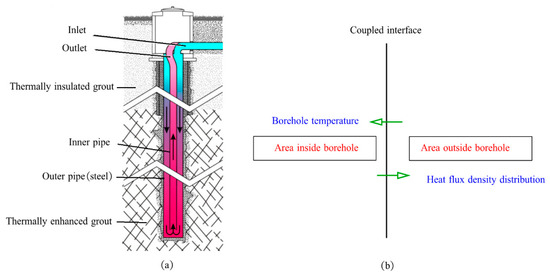
Figure 1.
Schematic of deep borehole heat exchanger. (a) Heat extraction during heating season; (b) coupling of the two areas for simulation.
An extensive thermal performance analysis is critical in need to assure long-time efficient and sustainable operation of DBHE [11,12,13,14]. Available related studies on heat transfer of DBHE have already started and mainly focus on the operation modeling of DBHE and evaluation of heat extraction output [6,7,8,9,10,11,12]. However, there is still a lack of comprehensive study on the thermal recovery characteristics of DBHE after heat extraction due to the complicated heat transfer with surrounding rock-soil of deep borehole [11,14,15]. In view of the real applications that DBHE usually operates discontinuously in the heating season and stops running during the intermittent period, it is crucial to develop adequate and convenient means for the overall thermal analysis under intermittent condition in order to have a sound knowledge of the thermal recovery characteristics. Additionally, the sustainability of DBHE at its design efficiency is now being questioned owing to annual imbalanced energy extraction underground especially in cold-climate regions, where buildings are heating-dominated [10,11]. Up to now, there are concerns regarding the long term thermal performance of DBHE, therefore, it is critical to study the thermal recovery characteristics of it after heating season in order to figure out whether it could run stable during the cyclic operation in the next years since poor thermal recovery condition after each heating season would undoubtedly lead to a considerable decline in the heat extraction output potential of DBHE year by year.
In summary, necessary thermal recovery after each heat extraction cycle should be properly considered to assure a DBHE’s long-term sustainable performance. In this paper, we focus on studying the thermal recovery characteristics of DBHE under intermittent condition, which contributes to the sustainable operation of it. This paper is organized as following, first of all, the challenge of thermal recovery simulation is analyzed and heat transfer modeling study on DBHE is summarized in Section 2. In Section 3, the methodology applicable to thermal response of DBHE under the intermittent condition is developed. Based on heat source theory and superposition principle, we extend the classical finite line source model to account for the vertical heat flux distribution varying along depth and heterogeneous thermal conductivities in the multi-layer rock zone. Moreover, a fast simulation approach employing the hybrid solutions for heat transfer analysis inside the borehole coupled with the extended finite line source model is put forward to depict the transient thermal response and dynamic thermal recovery of rock zone outside borehole. To the authors’ knowledge, no such algorithm for deep BHE has yet been suggested in the previous literatures. In order to verify and confirm the reliability and efficiency of the recommended method, the DBHE model in study are explained in detail in Section 4, where basic model setup and operation parameters during heating season are summarized for intermittence simulation. Immediately, simulation results and calculation cost from it are examined through a cross check against the detailed solution of the unsteady state heat transfer problem at refined time step and spatial resolution in Section 5. Specifically, borehole temperature evolution with time during the intermittent period as well as thermal performance of DBHE during heating season in a three-year cyclic operation with intermittence after heat extraction are compared carefully. Finally, concluding remarks and future research about the problem are discussed in Section 6.
2. Simulation Study on Heat Transfer of Deep Borehole Heat Exchanger
Over the past decades, heat transfer in borehole heat exchangers has been fully studied, and great effort was devoted to the borehole heat transfer models attracting the development and use of analytical solutions [15,16]. These analytical heat transfer models can be made computationally cost effective and have been widely applied in various engineering applications [16,17,18,19,20,21,22,23,24]. Despite the appeal of these endeavors, these aforementioned current analytical approaches represent oversimplifications of the actual BHEs and remain limited to a few constraining assumptions, especially the thermal conditions of the geological medium (for example, ideal homogeneous medium of rock or soil underground with constant thermal properties, uniform heat flux distribution along borehole, and the constant initial temperature of rock–soil that have been discussed in many studies), which seems unreasonable to describe the characteristics of deep geothermal directly, since the geological conditions for deep BHEs over 2000 m in depth would be vertically heterogeneous, and the geothermal gradient in DBHE constitutes a key factor of its performance. Also, they are generally not capable of describing all the involved phenomena and therefore lack some of the accuracy, flexibility, and transparency gained from numerical methods.
Actually, thermal response of DBHE under intermittent condition is a three-dimensional unsteady state heat transfer problem in essence, which varies over different time and space scales [15,16,17,18,19,20]. Specifically, the time scale ranges from sub-hours to several months or even decades. On the other hand, layout of DBHE brings about geometric complexity, where the space scale ranges from borehole radius at the scale of millimeter to the vertical length at the scale of thousand meters. Moreover, physical model depicting this heat transfer problem is rather complex where many factors are involved including the heat extraction output in history, interaction between borehole and rock or soil [4,5,22], heterogeneity of multi-geological layers [23,25,26], influence of groundwater advection [24], widely distributed ground thermal parameters [25,26,27], etc.
Numerical modeling appears to be a practical complement for analytical solutions to account for the complexity of the geological effect and heat transfer process through detailed discretization schemes, this approach, such as OpenGeoSys (Kolditz et al., 2012) [28] and FEFLOW(Diersch et al., 2014) [29], can consider all the relevant thermo-physical properties of the BHE and capture the physical parameters of the borefield in high detail but result in high computational cost. Moreover, mesh has to be created manually under the framework of the fully discretized models which prohibits fast simulations. Therefore, a simulation tool has to be developed that satisfies the following requirements: high physical detail of the model at acceptable computational speed, which is more applicable for the design and optimization problems that require iterative calculations.
There are some investigations on the modeling and simulation of heat transfer characteristics of DBHE recently and a systematic investigation on its thermal performance under operating condition has been summarized. Wang et al. [30] carried a numerical investigation on the heat transfer characteristics and optimal design of the heat exchangers of a deep borehole ground source heat pump system, a field test was also performed in their work considering the lack of experiment verification of simulation study of DBHE, however, in their model only continuous condition was studied without intermittent state simulation. Chen and Shao et al. [31] implemented a FEM numerical model in the open source software OpenGeoSys for the performance analysis of the DBHE. Kong et al. [32] used FEM to demonstrate the feasibility of long-term and short-term operations of DBHE by considering the effect of geothermal gradients. Ma [33] proposed a heat transfer analytical model for downhole coaxial heat exchangers and the piecewise calculation method was adopted both on the time scale and in the depth dimension. It was concluded that the heat transfer of DBHE could be improved by increasing the Reynolds number, but its increments gradually decreased. Fang et al. [7] developed a computational efficient method for thermal analysis by finite difference method and the numerical algorithm were validated by the reference data from simulation results by finite element method, however, the dynamic heat propagation front for thermal affecting radius evolution with time in the radial direction was not analyzed physically, and the thermal response was only simulated through the given annual load profile, and the intermittent condition was not studied.
In reference [34], we conducted a comprehensive analysis on the dynamic heat transfer process of DBHE under operation condition and proposed an efficient modeling approach for the problem, where thermal performance of DBHE was clearly described by the input operation parameters (flow rate or inlet temperature) coupled with the transient rock or soil temperature distribution outside the borehole. If the DBHE operates discontinuously in the heating season or one studies the thermal recovery characteristic of temperature field in the rock during the intermittent period, there exists a relatively swift change of heat flux distribution along the DBHE compared to the operating condition. Due to the fact that vertical heat conduction along the depth could not be negligible for thermal recovery analysis compared to the scenario under the operating condition where radial heat conduction dominates, the description of constantly propagation front for thermal affecting radius evolution with time (as depicted in Figure 2) would fail to give reasonable solution for the transition from operation to intermittent condition, thus leading to a large deviation of simulated thermal response outside borehole from the actual situation. As a matter of fact, physical modeling for transient thermal affecting zone in the rock and heat flux distribution along the borehole in reference [34] is valid for operating condition, not proper for the simulation of thermal recovery outside the borehole under the intermittent state.
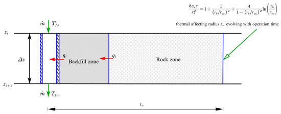
Figure 2.
Dynamic evolution of thermal affecting radius in the rock zone.
An efficient simulation approach to thermal recovery is essential for operation strategy implementation of DBHE in practice where the key issue focuses on how many days should be properly spared for its recovery after heat extraction to achieve sustainable operation in each cycle. In next section, the methodology applicable to thermal response of DBHE under the intermittent condition will be introduced in detail.
3. Methodology for Thermal Response of DBHE under the Intermittent Condition
Because of all the complications of this problem and its long-time scale, the heat transfer process may usually be analyzed in two separated regions (as shown in Figure 1b). One is the solid soil/rock outside the borehole, where the heat conduction must be treated as a transient process. Analytical methods treat the BHE as either a line source or cylinder source in semi-infinite medium with uniform initial temperature. Another sector often segregated for analysis is the region inside the borehole, including the grout, the pipes and the circulating fluid inside the pipes [16]. The main objective of this analysis is to determine the inlet and outlet temperatures of the circulating fluid according to the borehole wall temperature and the heat exchange rate of the BHE. Detailed analyses on single U-tube, double U-tube, and coaxial tube boreholes have been available [16]. The two separate regions must be linked on the borehole wall where a uniform temperature distribution is usually assumed.
In this section, the whole simulation procedure for describing the transient heat transfer inside borehole and dynamic thermal recovery of rock zone outside borehole is presented in detail. In 3.1~3.2, we adopt the finite line source model based on the classical heat source theory and superposition principle for the dynamic thermal recovery in the rock zone outside the borehole. It originates from Eskilson’s concept [15] but is enhanced to account for the heterogeneous distribution of heat source intensity as well as thermal conductivities in the multi-layer rock zone. Immediately, a fast simulation approach for heat transfer inside the borehole on the basis of quasi-steady state model is formulated in Section 3.3, followed by Section 3.4, where coupling of the two areas inside and outside the borehole under the intermittent condition is summarized.
3.1. Transient Point Source Solution for Heat Transfer Outside Borehole
Temperature field evolution of the rock under intermittent condition can be regarded as the thermal response in the semi-infinite medium to the overall contribution of step heat impulses at different time and different heat flux intensity (i.e., constant heat flow at a certain time interval depicted in Figure 3) released by a finite line source located at the borehole [14,15,16]. What should be noted is that transient heat flux intensity varies along the DBHE compared to the shallow BHE, so the step heat impulses vary both with time and space [16,17,18,19,20]. The required approach for such a problem is a transient analysis of ground response to different heat loads at different time scales.
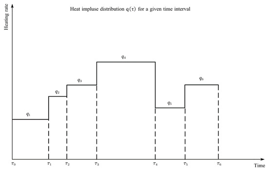
Figure 3.
Transient heat impulse rate distributed in discrete time steps.
A computationally efficient way to tackle the problem is heat source theory, which provides analytical determination of the contribution of given heat pulses to the overall thermal response of the rock segments located at arbitrary depth underground. Heat source theory has a very clear and simple physical meanings: Changes in temperature distribution over time is a function of the internal heat source, thermal interaction of the boundary, and the initial temperature distribution. These thermal effects can be regarded as a generalized heat source [15]. In view of time scale, the heat source can be continuous, if the action time is short enough, it can also be abstracted into a transient heat source. Similarly, the heat source is spatially distributed, but if the spatial scale of the heat source is small enough, it can be abstracted into a point heat source, a line heat source, or a surface heat source. For the linear heat conduction problem, the temperature field caused by various complex heat sources can be obtained by the superposition of temperature fields caused by all the instantaneous heat sources. This is the basic idea of the Green function method for solving the problem of unsteady heat conduction [35]. Thermal response in an infinite homogenous medium at time for position due to an instantaneous point source of unit strength generated at time and at point is named the three-dimensional Green function, and is given by Carslaw and Jaeger [15,16] as
where is the thermal diffusivity of the medium.
Consider the heat source points distributed uniformly with intensity along axis releasing heat continuously from to in a homogenous medium (with the specific heat capacity of and density of ), due to the linear characteristics of the problem, one can obtain the overall temperature response located at point and at time by integrating Green function (Equation (1)) with respect to time and space position (refer to Appendix A) as:
3.2. Extended Finite Line Source Model
In Figure 4, a line of point source of intensity is inserted in a semi-infinite homogeneous rock such that the line is perpendicular to the rock surface . The solution to this problem can be obtained by the method of images [15,16], imaging a mirror-image line of heat sinks exists.
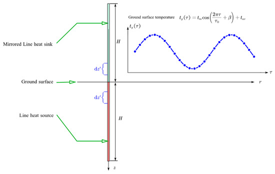
Figure 4.
Finite line source model.
This symmetrical distribution of line source and sink at the medium surface can maintain the surplus temperature of the rock surface at zero. In this situation, the contribution of the line source and line sink to the temperature response at time for position is given by integrating the continuous point source along the following line:
where , and are the density, specific heat capacity and thermal diffusivity of rock, respectively.
Considering the heat source intensity distribution homogenous along the line (as the case of shallow BHEs), integral of Equation (3) over gives the solution of finite line source model as
Derivation of complementary error function in Equation (4) employs the definition as
For the deep borehole heat exchanger, heat source intensity distribution varies significantly along the depth, so classical finite line source model could be minorly modified as
where , .
Due to the ground heterogeneity and length of the borehole, DBHE crosses usually several geological layers. If the heterogeneous thermal conductivities distribution outside the borehole is considered, according to the point source solution based on Green function, thermal response at point could be further modified (according to Appendix B) as
Equation (7) gives the whole formulation of extended finite line source model, where the heterogeneity of vertical heat source intensity distribution and thermal conductivities in the multi-layer rock zone are considered as a further improvement of classical finite line source model applied in shallow BHE simulation. It should be noted that, here, is the thermal conductivity at the position of line source, and is the localized thermal diffusion coefficient at the point .Given the simulation time step of DBHE, assuming that step heat impulses starts at time and terminates at time , thermal response outside the borehole at the time due to step heat impulse reads as
where is the intensity of the heat flux of the line source at the time , and the g-function is the formula in Equation (7).
As mentioned above, thermal response outside the borehole could be decomposed into a superposition of solution due to all the step heat impulses [15,16]. The overall contribution of step heat impulses is
This method quantitatively reflects the influence of transient heat flux distribution along the DBHE on the dynamic heat transfer process in the rock by analytical functions under intermittent condition, thus the calculation cost is greatly reduced. At the same time, it can accurately reflect the rock temperature evolution on a hour-to-hour, day-to-day, or month-by-month basis, taking into account the short or long-term effects of heat accumulation throughout the entire intermittent cycle (hours or months) of borehole heat exchangers [15,16].
3.3. Fast Simulation of Heat Transfer inside the Borehole
3.3.1. Quasi-Steady State Modeling of DBHE inside the Borehole
The quasi-steady state model has been widely applied for thermal analysis inside the borehole, assuming that the fluid temperature and pipe wall vary in the axial direction and temperature of the inlet and outlet of the circulating fluid changes with time due to the heat flux distribution along the borehole wall determined by the temperature difference and thermal resistance. The model is able to evaluate the influence of short-circulating among the branch pipes [16].
During thermal recovery of DBHE, return water from the heat pump units flows into the inner pipe (circular domain) and circulates out from the outer pipe (annular domain). On the basis of the energy equilibrium equations for upward and downward flow of the circulating fluid in DBHE shown in Figure 5 are formulated to model the dynamic heat transfer process. According to the quasi-steady state heat transfer analysis inside the borehole, it is assumed that convection overweighs conduction for the circulating fluid in pipes along the axial direction and the temperature and velocity distribution of the fluid in pipes at any cross section are uniform, turbulence influence on heat transfer could be incorporated into the convection coefficient by lumped parameter method. Therefore, the temperatures of the fluid flowing upward in the outer tube (named as pipe 1) and downward in the inner tube (named as pipe 2) vary along the depth as
where is the fluid flowrate, denotes the specific heat capacity of fluid, and are the fluid temperatures in the outer and inner pipe along depth, and are the local heat flow between the flow pipes and the borehole wall, respectively.

Figure 5.
Quasi–steady state heat transfer analysis based on energy equilibrium inside the borehole.
3.3.2. TRCM Model for Thermal Resistances within the Borehole
Thermal resistances within the borehole can be implemented into the quasi-steady state heat transfer model by applying the methods in analogy to the electric networks. A geometrical simplification is made such that the different parts of the borehole are represented by single nodes (as depicted in Figure 6).
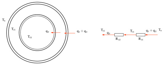
Figure 6.
Cross section of annular pipe borehole and the corresponding thermal circuit.
Numerical models based on this methodology have earlier been referred to as the thermal resistance and capacity model (TRCM), the TRCM model for coaxial BHEs have been published by Ref [36]. A thermal circuit would be used to describe the local heat flow between the flow pipes and the borehole wall and heat flow as functions of the temperature difference, and derive the corresponding thermal resistances of outer pipe to the borehole wall and inner pipe to the outer pipe :
where and are the thermal conductivities of backfills and DBHE annulus or inner pipe (denoted as i or o) respectively, while ,, are the radius of the outer pipe and inner pipe as well as borehole, is the convection coefficient calculated by
and , are the Reynolds number and Prandtl number of the circulating flow, respectively.
Consistently, the local heat flow between the flow pipes and the borehole wall in the quasi steady state model of DBHE inside the borehole could be formulated as
Therefore, we can obtain the quasi-steady state heat transfer equation for fluid flow inside the borehole
The boundary condition for heat transfer in differential Equation (14) are
where is the inlet temperature of the circulating fluid and denotes the borehole depth.
Introducing the variables:, then numerical solution of Equation (14) could be carried out by central difference schemes:
where the subscript denotes the DBHE discrete element.
For the thermal analysis inside the borehole in the case of an intermittent loop of DBHE, a fast simulation technique is employed without turning to the time-consuming calculations of unsteady-state heat conduction equations for rock and fluid in the pipes in axial and radial direction respectively. Actually, due to difference in water density, a circulation pressure arises in the DBHE, no pumping work is needed for minor flow circulation. Specifically, we consider the flow circulates with a minor volumetric flow rate valued at 0.01~0.1 m3/h continuously downward in the inner pipe and upward in the annulus, and the inlet temperature of the next cycle is set as the flow temperature circulating out of the annulus in the previous cycle.
3.4. Coupling of the Two Area inside and outside a Borehole under Intermittent Condition
The two areas exchange information each other and coupling of them lies in the intermediate temperature of borehole wall as boundary condition as described in Figure 7. Given the temperature of the borehole wall, heat flux distribution along the borehole could be determined and transferred to the quasi-steady state model inside the borehole.
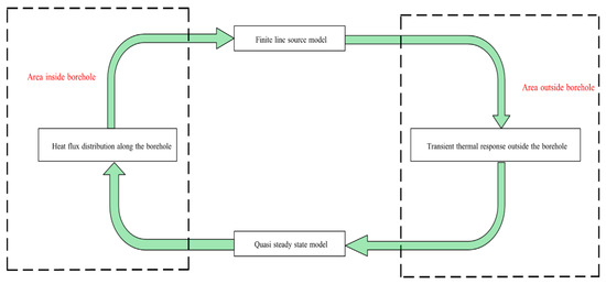
Figure 7.
Coupling of the two area inside and outside borehole under intermittent condition for calculation of temperature distribution of each branch pipes. On the basis of the heat flux distribution, transient thermal response outside the borehole could be simulated by the extended finite line source model and temperature distribution along the borehole wall is also determined meanwhile which is transferred to the calculation of heat flux distribution.
4. Model Setup
In order to study the intermittence characteristics of DBHE and get a profound knowledge of how many days should be properly spared for its recovery after heat extraction to achieve sustainable operation in each cycle, we carried out a comprehensive simulation on the basis of the proposed method for the dynamic thermal recovery of DBHE. Geological settings for the DBHE in the study are depicted in Figure 8. It should be noted that the DBHE in the study comes from a pilot demonstration project in Qingdao, located in Shandong Province, China. The coaxial tube DBHE was installed in a deep borehole with an overall depth of 2600 m and a drilling diameter of 216 mm. The DBHE wall is made of steel and has an outer diameter of 178 mm and a thickness of 9.5 mm. The inner pipe is made of high temperature resistant material applied in oil collection engineering with a lower thermal conductivity of 0.01 W/m/K, whose diameter is valued at 90 mm with a thickness of 10 mm. In situ field tests for the project will be introduced in our future work; this paper focus on the simulation results for its thermal recovery after heat extraction.
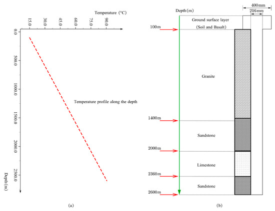
Figure 8.
Geological settings for the model in the study. (a) Initial geothermal temperature profile underground; (b) rock layers distribution.
Establishment of the heat transfer model for DBHE includes the following three aspects in general:
4.1. Input Variations
The input variations of the simulator can be classified into the following four groups. i. geological data—all the related geological parameters for geothermal temperature and groundwater condition and rock/soil multi-layer properties are shown in Table 1 and Table 2; ii. DBHE structural parameters—borehole section and geometry settings of DBHE are listed in Table 3; iii. operating condition parameters—the parameters settings for operation condition during the heating season include inlet flow temperature, flow rate, operation hours and intermittent days, etc. (see Table 4); and iv. material parameters—the properties of the circulating water, inner pipe, and backfill materials used in the model are summarized in Table 5.

Table 1.
Geological parameters of deep borehole.

Table 2.
Properties of the rock/soil layers.

Table 3.
The construction parameters of the deep borehole heat exchanger (DBHE).

Table 4.
The operation parameters of DBHE in the heating season.

Table 5.
Thermal parameters of the fluid, backfill material, inner pipe and outer pipe in the model.
4.2. Boundary Conditions
With respect to the rock zone, initial geothermal temperature distribution is set as the far field boundary in the radial direction along the depth, and isothermal boundary is considered at the bottom of DBHE. In the shallow layer of the rock, zero heat flux boundary is set below the constant temperature layer without consideration of the variable temperature zone due to atmosphere influence for simplicity of simulation.
4.3. Model Discretization
In the scenario studied, the DBHE with a depth of 2600m is discretized into 1500 segments vertically and uniform grids with a scale of 0.5 m that are applied in the radial direction.
5. Model Validation
In this section, dynamic thermal recovery of DBHE during the 205 days intermittence after heat extraction is simulated by applying the fast simulation approach. In order to validate the fast simulation approach, a cross check is also performed using the detailed heat transfer solution (or full 3D numerical solution) obtained by solving the complex unsteady state heat transfer equations within the borehole coupled with the rock outside the borehole based on full discretization numerical schemes at small time steps and refined spatial resolution.
5.1. Simulation Results from the Proposed Method
5.1.1. Thermal Recovery Analysis of DBHE after Heat Extraction
Figure 9 presents the simulation results based on the fast simulation approach for the dynamic evolution process of thermal recovery of DBHE during the 205 days of intermittence after 120 days heat extraction. It could be seen clearly that there exists a fast recovery stage from one day to 65 days when coldness due to heat extraction soon diffuses away and rock recovers at a comparatively faster speed, however after 65 days until to the end of thermal recovery at 205 days, the recovery speed slows down, and minor variation was observed in the rock temperature field, indicating that the evolution has basically finished. At 205 days, rock temperature recovers almost to its initial undisturbed state and only subtle temperature decline exists near the borehole. Moreover, basically no temperature decline could be observed in the rock at the deepest as a bottom boundary, which proves that heat extracted from radial direction contributes more to thermal recovery than vertical heat conduction from deep rock.
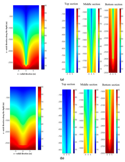
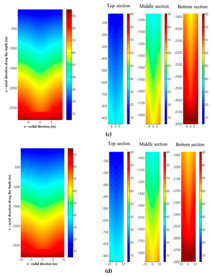
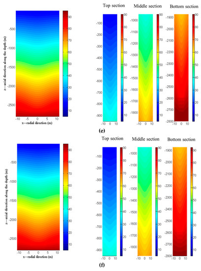
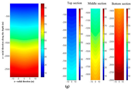
Figure 9.
Temperature field evolution underground with time during the intermittent period for thermal recovery after heat extraction. (*The left figure is the overall temperature distribution after different days of thermal recovery, the right figure shows the detailed variation for top, middle and bottom sections of the deep borehole; (a) 1 day, (b) 15 days, (c) 40 days, (d) 65 days, (e) 115 days, (f) 165 days, (g) 205 days; rock temperature unit is °C in the color bar).
In order to investigate the recovery condition of rock along depth, thermal recovery coefficient can be defined and calculated as follows:
where is the initial rock temperature, denotes the rock temperature, and is the total number of rock segment in the thermal affecting scope at depth , respectively.
Simulation results about borehole temperature evolution and thermal recovery coefficient of rock along depth with time during the intermittent period are summarized in Figure 10. We can see that after the fast recovery stage, rock temperature basically recovered to its initial distribution along depth and the thermal recovery coefficient varied from 0.9 at one day to 0.96 at 65 days until 0.99 at 205 days during the intermittent period. Therefore, it can be safely concluded that, given sufficient time for thermal recovery, coldness accumulation near borehole would be effectively eliminated after the heating season, which would not affect the potential of subsequent heating in the following years. The critical recovery time depends on the thermal diffusion coefficient of rock as well as heat extraction load of DBHE, and it should not be less than 65 days, as in this model, to ensure that thermal performance of DBHE in the next cyclic operation period would not worsen.
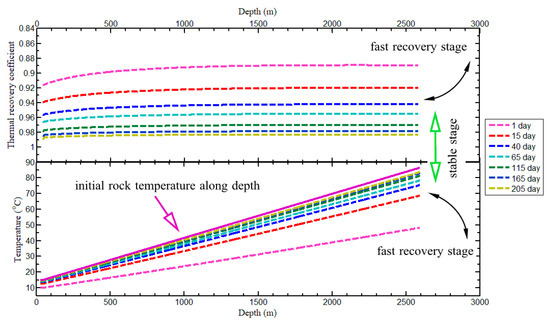
Figure 10.
Borehole temperature evolution and thermal recovery coefficient of rock along depth with time during the intermittent period for thermal recovery after heat extraction.
5.1.2. Comparison with the Detailed Heat Transfer Solution
In order to validate the fast simulation approach, simulation results of borehole temperature distribution along depth during the intermittent period are compared with the detailed heat transfer solution in Figure 11. Good agreement was achieved, as it shows during the thermal recovery stage from one day to 15 days, 40 days, and 65 days until 205 days in the end. Subtle differences exist between the simulation results (no more than 0.5 °C, see Table 6 for detail), which demonstrates the reliability and robustness of our method. Moreover, due to the fact that minor heat flux extraction (close to 0 W/m) from the rock is distributed along depth during the intermittent condition, fluid temperature in the annulus stays in equilibrium state with borehole wall where basically no temperature difference could be observed along depth. Therefore, the simulated borehole wall temperature approximately equals to that of fluid inside the borehole. We can see that fluid temperature in the DBHE increases linearly from top to the bottom at the end of intermittence as shown in Figure 11. This observation verifies our assumption in Section 3.3 that vertical distribution of water temperature leads to difference in water density, thus a circulation pressure in the DBHE arises for minor flow circulation eventually.
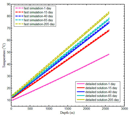
Figure 11.
Temperature evolution of borehole wall (also fluid temperature in the annulus of DBHE) along depth with time during the intermittent period for thermal recovery after heat extraction.

Table 6.
Comparison between detailed solution and fast simulation for intermittence condition.
To further characterize the thermal performance of DBHE running in a cyclic operation mode with intermittence after heat extraction, Figure 12 gives three-year round simulation results of DBHE performance during heating seasons with 205 days intermittence. Owing to the perfect thermal recovery condition, it could be seen that heat extraction output which is basically not affected after each cycle stabilizes approximately at 387KW with the outflow temperature of 11.76 °C. Also, a comparison of the prediction results for thermal performance during the heating season is depicted in Figure 12, where the intermittent condition after heat extraction is simulated by the fast simulation approach and full 3D numerical schemes in reference, respectively. Clearly, it shows that the outflow temperature and heat extraction rate of the coaxial DBHE during the stable stage of the heating season predicted by the fast simulation approach are 11.0 °C and 351 KW, respectively, indicating that both the outflow temperature and heat extraction rate in the subsequent cycle after intermittence are in good agreement with the full 3-D numerical solution in reference (with a relative error of 6.36% for the outflow temperature, and 9.3% for the heat extraction rate). Moreover, during the intermittent period of the second year, temperatures at borehole bottom are 83.64 °C and 84.31 °C from the two approaches respectively, as depicted in Figure 12a. The relative error is 0.79%, which is so minor as to be safely neglected. This observation indicates that rock temperature field under the intermittent condition (which provides initial condition for the simulation of operation state of DBHE in the next cycle) obtained by the fast simulation approach proposed in the paper is quite reasonable and reliable.
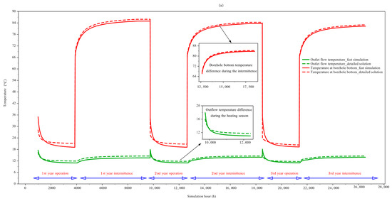
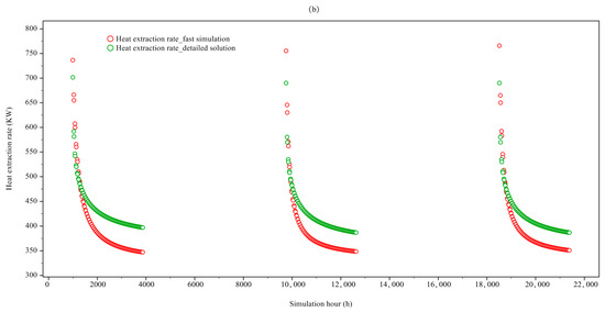
Figure 12.
Comparison of the simulation results for thermal performance of DBHE in a three-year cyclic operation with intermittence. (*(a) shows the temperature response of the circulating water and borehole bottom; (b) represents the heat extraction rate; operation parameters of DBHE in the heating season are summarized in Table 4.)
5.1.3. Mesh Independence Test
The temporal and spatial size determines the accuracy of results and computational efficiency. The impact of step size on the computational stability was analyzed in this part. Considering that the thermal response function in finite line source model is characterized for the cross-scale merit with respect to simulation time, therefore, a large time step can be safely chosen. The temporal step size was set as 0.5 h, 1 h, 3 h,12 h. With different time steps, the simulated results of borehole bottom temperature during the intermittent period for 205 days were compared in Figure 13, which shows that during the first 40 days unsteady stage, larger deviations exist among the borehole temperatures of different time steps compared with the detailed solution, and then the deviations gradually decrease and stabilize during the steady stage from 40 days to 205 days. With the temporal step size less than or equal to 3 h, the simulated temperatures have the maximum relative error of 1.92%. Therefore, 3 h is selected as the time step for calculation.
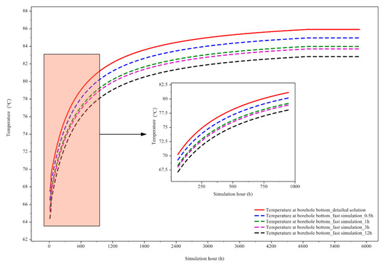
Figure 13.
Comparison of borehole bottom temperatures of deep borehole heat exchanger for 205 days intermittence with different time steps.
The effect of spatial step in direction was also analyzed. The step was set from 0.1 m to 5 m (the time step is 3 h) for simulation of the borehole bottom temperature at the 40th day of intermittence. The comparison results were shown in Figure 14. The simulated borehole bottom temperature keeps constant, when the is less than or equal to 1m. Accordingly, 1m is considered as the step size in the simulation. In this scenario, the number of nodes is 2600.
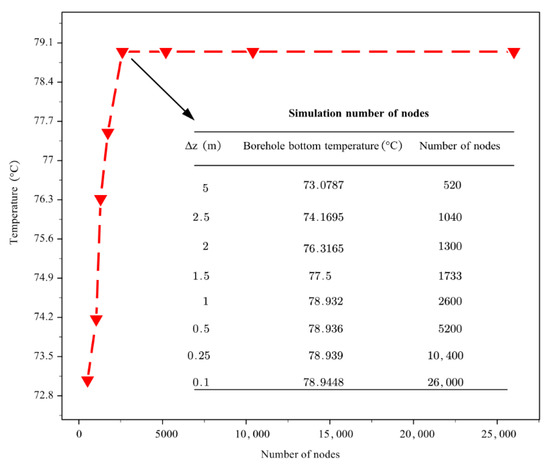
Figure 14.
Comparison of borehole bottom temperatures of deep borehole heat exchanger for 205 days intermittence with different step size in z direction along depth.
5.2. Simulation Efficiency and Precision Validation
In our calculation, the extended finite line source model characterized by the cross-scale merit of simulation time is employed for fast spatial and temporal superposition of the heat impulses to evaluate their corresponding thermal response contributions under the intermittent condition. Thanks to the high efficiency of calculation in the fast simulation approach, the update time step could be large enough without oscillation of the calculation results, which could be set comparable to the running hours or even several days during the intermittent period.
Calculation cost and borehole temperature (at the top and bottom) for 205 days intermittence of DBHE based on our fast simulation approach versus traditional detailed solution solving the unsteady state heat conduction problem are summarized in Table 6. The proposed fast simulation approach is more efficient depicting the dynamic thermal recovery outside borehole of DBHE under the intermittent state compared with the time-consuming full 3D numerical calculation for spatial and temporal temperature field distribution in the rock. According to our simulation, the computation task of the DBHE model with an intermittence of 205 days took only around 7.5 h on a common computer with a CPU of 2.9 GHz and 16 GB of RAM (A Thinkpad laptop from Guangdong, China, manufactured by Shenzhen Mingyanfeng Technology Co., Ltd which is also the developer and distributor). Regarding the calculation speed, around 13 times acceleration can be achieved (7.5h versus 96.6h by full 3D numerical calculation). Moreover, the proposed fast simulation approach for transient thermal response of DBHE under intermittent condition in this paper is also promising for generalized use with various vertical closed borehole heat exchanger configurations at an arbitrary length (including single U-type, double U-type, and coaxial pipe applied in shallow geothermal energy exploitation scenarios and large U-shaped or L-type geothermal wells for medium and deep hot dry rock energy utilization). Simulation of DBHE with other configurations based on the method will be introduced in our future work as a complement to the deep coaxial BHE in this study.
6. Conclusions
This paper formulated and presented a fast simulation approach for DBHE under intermittent condition, and a comprehensive study of the dynamic thermal recovery characteristics after heat extraction was carried out on a concrete DBHE model. First of all, we extend the classical finite line source model based on heat source theory and superposition principle to account for the vertical heat flux distribution varying along depth and heterogeneous thermal conductivities in the multi-layer rock zone. Moreover, a fast simulation approach for heat transfer analysis inside the borehole coupled with the extended finite line source model is put forward to depict the transient thermal response and dynamic thermal recovery of rock zone outside borehole.
Based on the efficient numerical model developed, a comprehensive study of the dynamic thermal recovery of DBHE during the 205 days intermittence after heat extraction was performed. Typical rock temperature evolution process during intermittence was observed which was further characterized from fast recovery stage to gradual recovery stage. The proposed efficient model was also verified by crosscheck with the detailed solution (full 3D numerical solution) for the unsteady heat conduction problem in the reference. To further test the efficiency of the proposed simulation approach, the calculation cost was also compared with that of full 3D numerical calculation at small time steps and a refined spatial resolution.
The key findings of this study can be summarized as follows:
- (1)
- The simulated results for borehole temperature vertical distribution along the DBHE during the intermittence on the basis of the proposed efficient simulation method are in good agreement with the detailed solution in reference. It is both efficient and reliable for engineering application. Moreover, it is also promising for generalized use for the transient thermal response of various vertical closed borehole heat exchanger configurations at arbitrary lengths under intermittent condition.
- (2)
- Given sufficient time for thermal recovery after heat extraction, coldness accumulation near the borehole will be effectively eliminated, and rock temperature recovers almost to its initial undisturbed state, which would not affect the potential of subsequent heat extraction in the following years.
- (3)
- There exists a fast recovery stage at the initial intermittence when coldness due to heat extraction soon diffuses away, then the recovery speed slows down gradually and minor variation could be observed. Moreover, basically no temperature decline could be observed in the deepest rock, as a bottom boundary proves that heat extracted from radial direction contributes more to thermal recovery than vertical heat conduction from deep rock.
- (4)
- After enough intermittence, the vertical increasing temperature distribution of water in the annulus leads to difference in water density, which is responsible for the circulation pressure in the DBHE for minor flow circulation eventually.
- (5)
- Comparison of the simulation results for thermal performance during the heating season in a three-year cyclic operation with 205 days intermittence after heat extraction shows that both the outflow temperature and heat extraction rate in the subsequent cycle after intermittence are in good agreement with the full 3D numerical solution in reference (with a relative error of 6.36% for the outflow temperature and 9.3% for the heat extraction rate).
Last but not the least, as the deep geology is more complex in contrast to shallow geology, geological logging technology for deep boreholes is necessary. Meanwhile, basic geological data should be accumulated to improve the accuracy of the numerical modeling for deep BHE. On the other hand, only intermittence after heat extraction of a DBHE was studied in this paper, in view of the higher initial capital cost of DBHE project than conventional shallow boreholes, it is worthwhile to further study how to achieve optimal operation with a proper intermittence strategy during the heating season in future work.
Author Contributions
Design and Conceptualization, Z.P. and Y.Z.; methodology, Y.Z.; software, Y.Z.; validation, Y.Z. and Z.M.; formal analysis, Z.M.; investigation, Y.Z.; resources, Y.Z.; data curation, Y.Z.; writing—original draft preparation, Y.Z.; writing—review and editing, Z.P. and Z.M.; visualization, Y.Z.; supervision, Z.M.; project administration, Z.P.; funding acquisition, Z.P.; All authors have read and agreed to the published version of the manuscript.
Funding
This work has been financially supported by the “Transformation Technologies for Clean Energy and Demonstration”, Strategic Priority Research Program of the Chinese Academy of Sciences (No. XDA 21020202).
Acknowledgments
The first author would acknowledge the great support of Jingtao Xia from Zhejiang Loopmaster Energy Technology Co., Ltd. for partial financial support to the study.
Conflicts of Interest
The authors declare no conflict of interest.
Appendix A. Thermal Response of Rock Due to Heat Source Based on Green Function
Consider the heat source points distributed uniformly with intensity along axis releasing heat continuously from to in a homogenous infinite medium with the initial temperature . If the influence of the ground as a boundary and the influence of the finite depth of the borehole are neglected, on the basis of the governing equation of the transient heat conduction, the boundary and initial conditions could be easily given under the following cylindrical coordinate:
Transient thermal response due to the infinite line heat source in the uniform medium in the cylindrical coordinate system can be obtained as follows:
Considering the integral over in Equation (A2) and its derivative with respect of as well as the boundary condition in Equation (A1) we have the following equation for :
According to Equation (A2), the transient thermal response could be formulated as:
Integral of Equation (A8), over gives the classical Kelvin infinite line source model Equation (2), which is relatively simple, ignoring the influence of the ground as a boundary. When the simulation time tends to infinity, the temperature field underground will not stabilize. For a finite line source with length , it was formulated as
In view of axial heat flow and ground temperature conditions, Eskilson [15] proposed the finite line source model and g-function method of dimensionless temperature response. The analytic solution of the finite line source model can be obtained by employing the virtual heat source and the Green function method.
Appendix B. Thermal Response of Rock under Heterogeneous Thermal Conductivities
If the heterogeneous thermal conductivities distribution in the simulation zone is considered, consider the following unsteady state heat conduction equation:
We perform local quasi-linearization of heat conduction equation with nonhomogenous thermal conductivity as
Herein, is the localized thermal diffusion coefficient, which is approximately regarded as a local constant equal to the thermal diffusion coefficient of the rock there.
According to the point source solution Equation (A5) based on the Green function, for the simulation zone outside borehole in the rock with heterogeneous thermal conductivities distribution, thermal response at point can be further modified as
where is the thermal conductivity at the position of the line source, is the localized thermal diffusion coefficient at the point , and , .
References
- Yang, H.; Cui, P.; Fang, Z. Vertical-borehole ground-coupled heat pumps: A review of models and systems. Appl. Energy 2010, 87, 16–27. [Google Scholar] [CrossRef]
- Li, H.; Nagano, K.; Lai, Y. Evaluating the performance of a large borehole ground source heat pump for greenhouses in northern Japan. Energy 2013, 63, 387–399. [Google Scholar] [CrossRef]
- Henrik, H.; Erling, N. Deep Borehole Heat Exchangers, Application to Ground Source Heat Pump Systems. In Proceedings of the World Geothermal Congress, Melbourne, VIC, Australia, 19–25 April 2015. [Google Scholar]
- Seama, K.F.; Marc, R. A Review of the Modeling of Thermally Interacting Multiple Boreholes. Sustainability 2013, 5, 2519–2536. [Google Scholar]
- Koohi-Fayegh, S.; Rosen, M.A. On thermally interacting multiple boreholes with variable heating strength: Comparison between analytical and numerical approaches. Sustainability 2012, 4, 1848–1866. [Google Scholar] [CrossRef]
- Sapinska-Sliwa, A.; Rosen, M.A.; Gonet, A.; Sliwa, T. Deep Borehole Heat Exchangers-A Conceptual and Comparative Review. Int. J. Air Cond. Refrig. 2016, 24, 1630001–1630015. [Google Scholar] [CrossRef]
- Fang, L.; Diao, N.; Shao, Z.; Zhu, K.; Fang, Z. A Computationally Efficient Numerical Model for Heat Transfer Simulation of Deep Borehole Heat Exchangers. Energy Build. 2018, 167, 79–88. [Google Scholar] [CrossRef]
- Holmberg, H.; Acuña, J.; Næss, E.; Sønju, O.K. Thermal evaluation of coaxial deep borehole heat exchangers. Renew. Energy 2016, 97, 65–76. [Google Scholar] [CrossRef]
- Bar, K.; Ruhaak, W.; Schulte, D. Seasonal high temperature heat storage with medium deep borehole heat exchangers. Energy Procedia 2015, 76, 351–360. [Google Scholar] [CrossRef]
- Schulte, D.O. Simulation and Optimization of Medium Deep Borehole Thermal Energy Storage Systems. Ph.D. Thesis, Technische Universitat, Darmstadt, Germany, 2016. [Google Scholar]
- Welsch, B.; Ruhaak, W.; Schulte, D. Characteristics of medium deep borehole thermal energy storage. Int. J. Energy Res. 2016, 40, 1855–1868. [Google Scholar] [CrossRef]
- Pan, S.; Kong, Y.; Chen, C.; Pang, Z.; Wang, J. Optimization of the utilization of deep borehole heat exchangers. Geotherm Energy 2020, 8. [Google Scholar] [CrossRef]
- Schulte, D.O.; Rühaak, W.; Oladyshkin, S.; Welsch, B.; Sass, I. Optimization of Medium-Deep Borehole Thermal Energy Storage Systems. Energy Technol. 2016, 4, 104–113. [Google Scholar] [CrossRef]
- Hellstrom, G.; Sanner, B. Earth Energy Designer: Software for Dimensioning of Deep Boreholes for Heat Extraction; Department of Mathematical Physics, Lund University: Lund, Sweden, 1994; pp. 185–192. [Google Scholar]
- Eskilson, P. Thermal Analysis of Heat Extraction Boreholes. Ph.D. Thesis, Department of Mathematical Physics, University of Lund, Lund, Sweden, 1987. [Google Scholar]
- Diao, N.R.; Fang, Z.H. Ground-Coupled Heat Pump Technology; Higher Education Press: Beijing, China, 2006; pp. 47–68. [Google Scholar]
- Rivera, J.A.; Blum, P.; Bayer, P. Ground energy balance for borehole heat exchangers: Vertical fluxes, groundwater and storage. Renew. Energy 2015, 83, 1341–1351. [Google Scholar] [CrossRef]
- Li, M.; Li, P.; Chan, V.; Lai, A.C.K. Full-scale temperature response function (G-function) for heat transfer by borehole ground heat exchangers (GHEs) from sub-hour to decades. Appl. Energy 2014, 136, 197–205. [Google Scholar] [CrossRef]
- Li, M.; Lai, A.C.K. Review of analytical models for heat transfer by vertical ground heat exchangers (GHEs): A perspective of time and space scales. Appl. Energy 2015, 151, 178–191. [Google Scholar] [CrossRef]
- Zhang, L.; Zhang, Q.; Huang, G. A transient quasi-3D entire time scale line source model for the fluid and ground temperature prediction of vertical ground heat exchangers (GHEs). Appl. Energy 2016, 170, 65–75. [Google Scholar] [CrossRef]
- Kim, E.J.; Bernier, M.; Cauret, O.; Roux, J.J. A hybrid reduced model for borehole heat exchangers over different time-scales and regions. Energy 2014, 77, 318–326. [Google Scholar] [CrossRef]
- Wang, J.; Long, E.; Qin, W. Numerical simulation of ground heat exchangers based on dynamic thermal boundary conditions in solid zone. Appl. Therm. Eng. 2013, 59, 106–115. [Google Scholar] [CrossRef]
- Abdelaziz, S.L.; Ozudogru, T.Y.; Olgun, C.G.; Martin, J.R. Multilayer finite line source model for vertical heat exchangers. Geothermics 2014, 51, 406–416. [Google Scholar] [CrossRef]
- Molina-Giraldo, N.; Blum, P.; Zhu, K.; Bayer, P.; Fang, Z. A moving finite line source model to simulate borehole heat exchangers with groundwater advection. Int. J. Therm. Sci. 2011, 50, 2506–2513. [Google Scholar] [CrossRef]
- Erol, S.; Francois, B. Multilayer analytical model for vertical ground heat exchanger with groundwater flow. Geothermics 2018, 71, 294–305. [Google Scholar] [CrossRef]
- Bnilam, N.; Al-Khoury, R. A spectral element model for nonhomogeneous heat flow in shallow geothermal systems. Int. J. Heat Mass Transf. 2017, 104, 703–717. [Google Scholar] [CrossRef]
- Sidiropoulos, E.; Tzimopoulos, C. Sensitivity analysis of a coupled heat and mass transfer model in unsaturated porous media. J. Hydrol. 1983, 64, 281–298. [Google Scholar] [CrossRef]
- Kolditz, O.; Bauer, S.; Bilke, L.; Böttcher, N.; Delfs, J.O.; Fisher, T.; Görke, U.J.; Kalbacher, T.; Kosakowski, G.; McDermott, C.I.; et al. OpenGeoSys: An open-source initiative for numerical simulation of thermo-hydro-mechanical/chemical (THM/C) processes in porous media. Environ. Earth Sci. 2012, 67, 589–599. [Google Scholar] [CrossRef]
- Diersch, H.J.G. FEFLOW: Finite Element Modeling of Flow, Mass and Heat Transport. In Porous and Fractured Media; Springer: Berlin/Heidelberg, Germany, 2014. [Google Scholar]
- Wang, Z.H.; Wang, F.H.; Liu, J.; Ma, Z.J.; Han, E.S.; Song, M.J. Field test and numerical investigation on the heat transfer characteristics and optimal design of the heat exchangers of a deep borehole ground source heat pump system. Energy Convers. Manag. 2017, 153, 603–615. [Google Scholar] [CrossRef]
- Chen, C.; Shao, H.; Naumov, D.; Kong, Y. Numerical investigation on the performance, sustainability, and efficiency of the deep borehole heat exchanger system for building heating. Geotherm. Energy 2019, 7, 1–26. [Google Scholar] [CrossRef]
- Kong, Y.L.; Chen, C.; Shao, H.; Pang, Z.H.; Xiong, L.P.; Wang, J.Y. Principle and capacity quantification of deep borehole heat exchangers. Chin. J. Geophys. 2017, 60, 4741–4752. [Google Scholar]
- Ma, L.; Zhao, Y.Z.; Yin, H.M.; Zhao, J. A coupled heat transfer model of medium-depth downhole coaxial heat exchanger based on the piecewise analytical solution. Energy Convers. Manag. 2020. [Google Scholar] [CrossRef]
- Zhao, Y.Z.; Pang, Z.H.; Huang, Y.H.; Ma, Z.B. An efficient model of deep borehole heat exchanger based on quantifying heat propagation front outside the borehole. Geotherm. Energy. 2020. under review. [Google Scholar]
- Morse, P.M.; Feshbach, H. Methods of Theoretical Physics, points. I and II; McGraw-Hill: New York, NY, USA; London, UK, 1953. [Google Scholar]
- Bauer, D.; Heidemann, W.; Müller-Steinhagen, H.; Diersch, H.J.G. Thermal resistance and capacity models for borehole heat exchangers. Int. J. Energy Res. 2011, 35, 312–320. [Google Scholar] [CrossRef]
© 2020 by the authors. Licensee MDPI, Basel, Switzerland. This article is an open access article distributed under the terms and conditions of the Creative Commons Attribution (CC BY) license (http://creativecommons.org/licenses/by/4.0/).