Article

Preliminary Analysis and Design of the Energy Conversion System for the Molten Salt Fast Reactor

1
Politecnico di Milano, Department of Energy, 20156 Milano, Italy
2
Istituto Nazionale di Fisica Nucleare, Sezione di Milano-Bicocca, 20126 Milano, Italy
3
TEC Division, DIME-Dipartimento di Ingegneria Meccanica, Energetica, Gestionale e dei Trasporti, Università degli Studi di Genova, 16145 Genova, Italy
4
Istituto Nazionale di Fisica Nucleare, Sezione di Genova, 16146 Genova, Italy
5
College of Nuclear Science and Technology, Harbin Engineering University, Harbin 150001, China
*
Author to whom correspondence should be addressed.
Sustainability 2020, 12(24), 10497; https://doi.org/10.3390/su122410497
Submission received: 12 November 2020 / Revised: 9 December 2020 / Accepted: 9 December 2020 / Published: 15 December 2020

Abstract

:
The unique design features of the molten salt fast reactor (MSFR) should enable higher coolant temperatures than in conventional water reactors, with a significant improvement in the achievable thermodynamic performance. The use of a molten salt as both fuel and coolant, however, poses several advanced heat transfer challenges, such as the design of innovative heat exchangers and energy conversion systems. In this work, we address a preliminary but quantitative analysis of the energy conversion system for the MSFR, based on reference design data from the SAMOFAR H2020-EURATOM project. We consider three main technologies, i.e., the supercritical steam cycle, the closed helium cycle and the helium/steam combined cycle. Preliminary design results are presented for each technology, based on a simplified modelling approach. The considered cycles show promising efficiency improvements, with the best performance being proven by the supercritical steam cycle. The analysis also highlights the critical issue related to the risk of freezing of the molten salts within the secondary heat exchangers, due to the low inlet temperatures of the working fluids. Results show potential incompatibility between the freezing point of molten salts and the temperatures typical of steam cycles, while helium cycles offer the best chances of freezing avoidance. The combined cycle promises intermediate performance in terms of thermodynamic efficiency and thermal compatibility with molten salts comparable with closed helium cycles.

1. Introduction

The molten salt fast reactor (MSFR) is one of the reactor concepts within the framework of the Generation IV International Forum [1]. What makes molten salt reactors (MSRs) peculiar with respect to conventional water reactors and other next generation reactor concepts is the employment of a liquid fuel. The molten salt, therefore, serves both as fuel and coolant, with enhanced safety and thermodynamic performance thanks to the absence of solid fuel elements within the core and to the low operating pressures. This comes at the cost of new challenges to be addressed, e.g., due to the adoption of non-conventional fluids, the presence of distributed internal heat generation [2] and substantially new dynamics and control features. Many of such technical issues involve the design of plant components, such as heat exchangers and power conversion systems. Additional challenges stem from the need to limit the total fuel salt inventory and to prevent the solidification of molten salts in the coldest regions of the primary and intermediate loops (Figure 1). The conspicuous power density of the MSFR and its compactness requirements represent relevant technical challenges, as demonstrated by the thermal issues involved in the design of the intermediate heat exchangers [3]. The characteristics of the MSFR core require the adoption of advanced heat transfer solutions to ensure large exchange surfaces in small volumes and acceptable pressure drops. Passive safety and natural circulation features impose even more severe requirements [4].
Despite the general renewal of interest in molten-salt-fuelled reactors, little effort has been made so far in the study of out-of-core MSFR subsystems. Given the compactness requirements of the reactor core and the properties of the proposed fuel salt mixtures, heat transfer and energy conversion are expected to play critical roles in the overall design of the plant. This work aims at a preliminary but quantitative analysis of thermodynamics aspects which are relevant to the design of the MSFR plant, with a focus on the analysis of the energy conversion system. The results of the present work can prove useful as reference data in the context of the ongoing studies on the design of the MSFR. Despite the focus on the MSFR as a most representative MSR technology [1], no intrinsic differences in terms of energy conversion performance should be expected between fast and thermal spectrum MSRs. The outcome of the analysis can therefore apply to MSR systems in general, provided that molten salt coolant properties and attainable temperatures are comparable to the ones here considered.
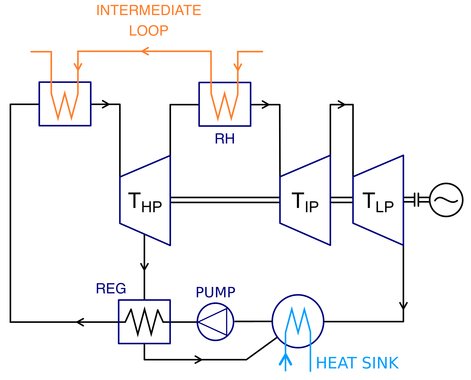
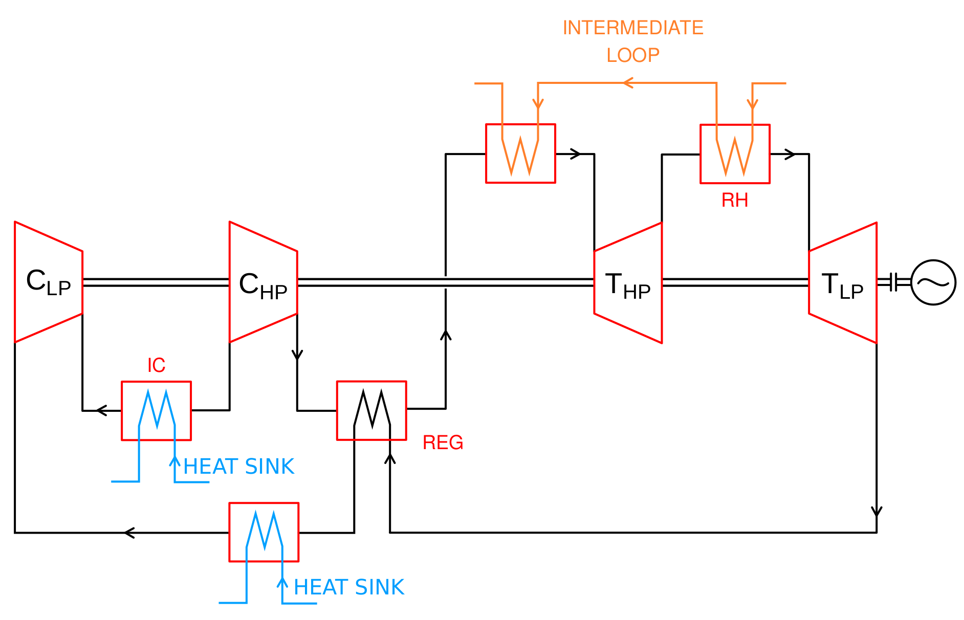
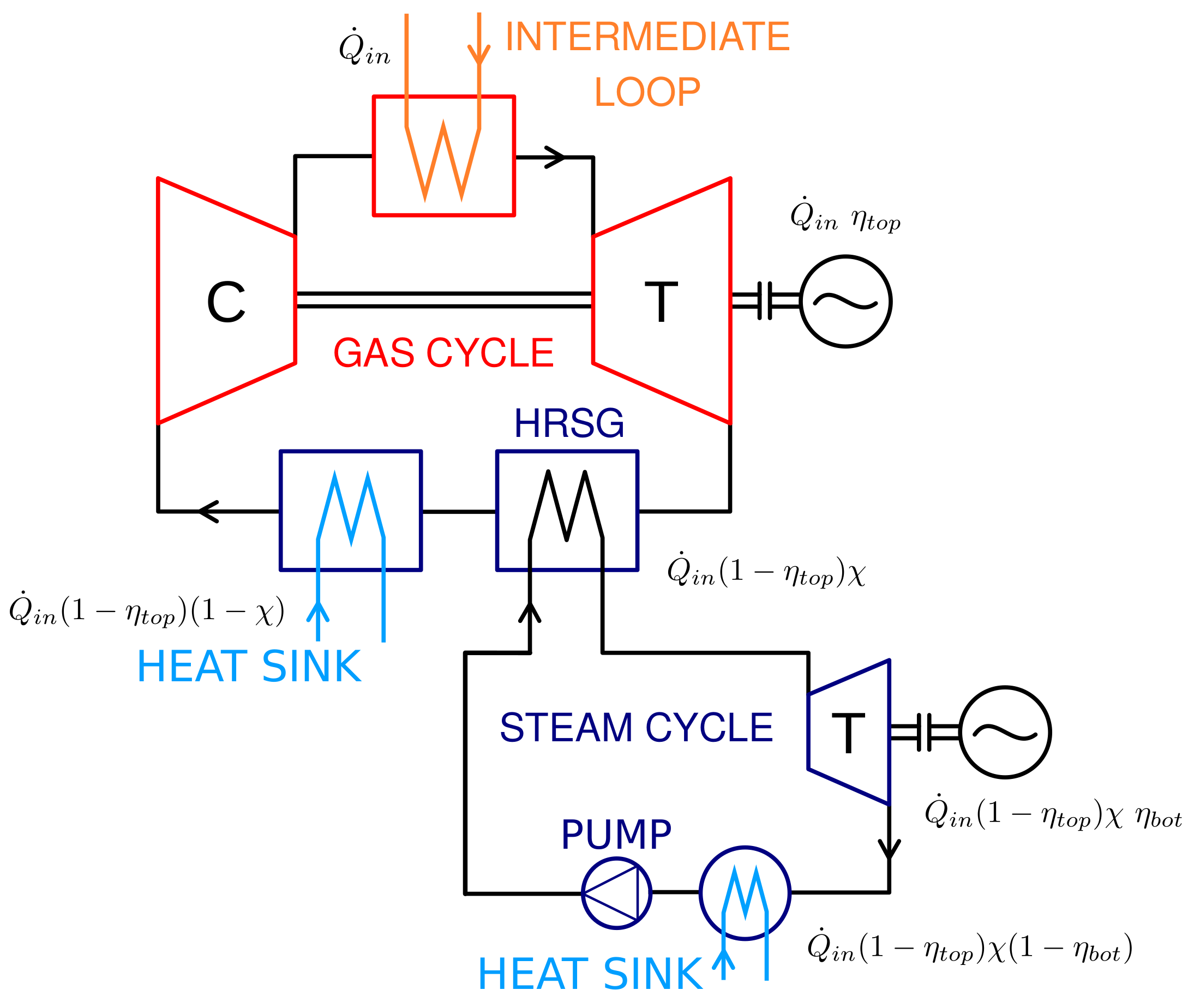
Three different thermodynamic cycles are considered, i.e., the supercritical steam cycle, the closed helium cycle and the helium/steam combined cycle. The supercritical steam cycle has not yet been employed in the nuclear industry [5], but is state-of-the-art technology in coal-fired high-temperature power generation [6]. Recent advancements include the integration of mature steam plant technology with CO2 capture [7] and thermal energy storage [8]. Helium cycles have been a major choice in the nuclear industry for gas-cooled reactors [9], while non-nuclear applications of helium-based gas cycles are far less common. Closed cycles based on other working fluids, such as air, nitrogen and supercritical CO2, have been considered for a wider range of power applications, including fossil fuels, concentrated solar power, biomass and waste heat [10]. On the other hand, air-based open cycles are the reference technology in gas-fired power plants [11]. Combined cycles are nowadays the most diffuse and efficient energy conversion technology for conventional power applications [12], in the standard air/steam configuration. Nuclear applications of combined cycles were the subjects of a recent investigation [13]. The proposed applications include small modular reactors (SMRs) [14] and high-temperature reactors for combined electricity/hydrogen production [15]. Helium/steam cycles for molten salt applications have not been investigated so far. Being that the focus of this study is also on the thermal coupling between molten salts and the working fluids of energy conversion systems, the combined cycle constitutes, despite its complexity in relation to the specific field of application, a promising choice in view of the combined benefits of molten salt/helium coupling and better thermodynamic performance with respect to simple gas cycles.
Even though a substantial improvement in terms of thermodynamic efficiency with respect to conventional light water reactors (LWRs) is expected, in the literature no thorough analysis has been yet performed to compare different technologies and to identify possible critical aspects related to the application of established or innovative power conversion technologies to the MSFR concept. The aim of the present work is therefore to propose preliminary designs for the three considered cycles, based on common design assumptions and reasonable parameter values. Results are compared in terms of achievable efficiencies and thermal compatibility between molten salt melting point and working fluid temperatures.
The paper is organised as follows. Section 2 contains the descriptions of data, models and assumptions employed in the study: The main design data of the MSFR (Section 2.1) which are adopted as the reference; a brief discussion on the choices of temperature parameters for the intermediate loop (Section 2.2), which ultimately define the heat source for the energy conversion system; and the three considered cycles (Section 2.3). For each of them we illustrate the main design assumptions and list the adopted design parameters. Results of the analysis are reported in Section 3. Section 4 contains a comparative discussion of the results, along with conclusive remarks and suggestions for further study.

2. Materials and Methods

2.1. Reference Design Data of the Molten Salt Fast Reactor

The MSFR is conceived, at the current design stage, as a large-size nuclear reactor for commercial power production. Its total thermal power output is intended to be around 3000 MW, with a net electrical power output in the 1000–1500 MW range, depending on the achievable plant conversion efficiency. The employment of a liquid fuel allows a low fuel inventory and a high power density, resulting in a very compact reactor geometry [16]. The reference MSFR data adopted in this work is the one proposed in the framework of the SAMOFAR [17] H2020-EURATOM project. Despite the extensive studies carried out on the reactor core, many design parameters are still to be defined. The primary and intermediate loop temperatures, which are of fundamental importance for the design of the intermediate heat exchangers, are not yet defined. The fuel salt temperature at core inlet and outlet are expected to be in the 650–700 and 750–800 °C ranges, respectively. Assuming a 100 °C core temperature rise, we selected 675 and 775 °C [16]. The main design parameters discussed so far and their adopted values are listed for reference in Table 1.
Two main fluorine-based options are considered, in the context of the SAMOFAR project, for the fuel salt composition [18]. The first one is LiF-ThF4-233UF4 (77.5–20–2.5 %mol), whereas the second one is LiF-ThF4-235UF4-(Pu-MA)F3 (77.5–6.6–12.3–3.6 %mol). The first one has not yet been characterised and, in general, properties of these salts depend on the exact composition (which might vary during the design process). Regarding the intermediate salt, several options are considered by the SAMOFAR project. They are all fluoride salts and their properties are generally similar. In this work, the LiF-NaF-KF (46.5–11.5–42 %mol) mixture, commonly known as FLiNaK, is considered, characterised by a melting point of 454 °C [19]. Different salt mixtures have been considered for other MSR concepts, most notably chlorine-based ones. Substantial differences between chloride and fluoride salts do exist, some of which may affect the overall reactor design, and their analysis is therefore out of the scope of this preliminary work. Significant effects of salt composition on the heat conversion performance should not be expected, given that main parameters (such as intermediate temperatures) are comparable. It has to be mentioned, however, that chloride salts have shown generally lower melting points [20] which could benefit the design of the intermediate circuit and of the energy conversion system.

2.2. Intermediate Loop Parameters

The advancement in power conversion technologies has seen, through the decades, a constant increase of cycle maximum temperatures [21]. Accordingly, all Generation-IV reactor concepts feature higher coolant temperatures than in LWRs, approximately ranging from 500 °C to 1000 °C [1]. The MSFR is not an exception, its core outlet temperature being between 750 and 800 °C. Since, in the MSFR, the molten salt serves both as fuel and reactor coolant, the heat source coincides with the molten salt itself, avoiding all the issues related to solid fuel performance and to fuel-to-coolant heat transfer. On the other hand, molten salts clearly cannot act as working fluids, and the reactor design also considers an intermediate inert molten salt circuit for safety purposes (Figure 1).
The choice of the intermediate loop temperatures can have a direct effect on the design of the energy conversion system. Since the thermodynamic cycle is mainly determined by its maximum and minimum temperatures, the intermediate temperatures do not affect directly thermodynamic efficiency of the cycles—as long as temperature profiles in the secondary heat exchangers are compatible. The impact of the choice of intermediate temperature is critical on the design of the heat exchangers, both the intermediate and secondary ones. As seen in [3], the current design of the MSFR poses severe limitations in the design of the intermediate heat exchangers. Such limitations lead to a very compact layout, small flow channels and large expected pressure drops on both sides. For this reason, relatively low temperatures in the intermediate loop are desirable to provide larger temperature differences and a smaller heat transfer surface. Regarding the secondary heat exchangers, intermediate temperatures play, again, major roles in determining temperature differences and mass flow rates, with relevant consequences on the design. To simplify the discussion, we fix the intermediate temperatures T c , i n and T c , o u t to 615 and 690 °C respectively, identifying a compromise between the design requirements of the intermediate heat exchangers and the better conversion efficiency ensured by high temperatures. Such values are coherent with the outcomes of the analysis carried out in [3]. The choice is not restrictive, as we will see, when for example steam cycles are concerned, as state-of-the-art steam technology allows maximum steam temperatures around 600 °C. Furthermore, the 615 °C lower value provides a margin of 30–50 °C with respect to typical freezing points of fuel salts [20], which is necessary to mitigate risks related to solidification during operation. A thorough analysis of the intermediate loop and of the heat exchangers is beyond the scope of the present work, but more detailed studies to prove the feasibility of the design options in terms of safety and cost-effectiveness will be subject of further work. A more detailed analysis on the performance of intermediate heat exchangers for the SAMOFAR MSFR design can be found in [3].

2.3. Energy Conversion Cycles

2.3.1. Supercritical Steam Cycle

Steam cycles are among the most widespread and the first thermodynamic cycles to be developed for power generation [21]. The key to obtain higher efficiencies is, in general, to introduce heat into the cycle at a higher average temperature, which can be done by simply increasing the evaporation pressure or by heating the steam above its saturation point (i.e., superheating). Other techniques that are commonly employed to increase the average temperature of heat introduction are reheating, where partially expanded steam is reheated up to a temperature level which usually is close to the primary steam temperature, and regeneration, where the irreversibility introduced by feedwater heating is reduced by supplying the heat internally, i.e., by extracting steam along its expansion and by making it exchange heat with the feedwater (Figure 2).
State-of-the-art steam plant technology has reached pressures and temperatures considerably higher than in the past. Steam generator outlet temperatures above 600 °C, at pressures of 300 bar or more, are now commonly adopted, along with the employment of supercritical water as working fluid [22,23]. Modern supercritical steam plants characterised by such parameter values, reach net efficiencies around 46–47%.
The cycle is designed by adopting several simplifying assumptions:
  • The main parameters, such as the evaporation/condensation pressures and the primary steam temperature, are fixed to values commonly adopted in modern steam plants.
  • Steam turbine: The steam turbine is divided into three sections (HP, IP and LP), each with a different, constant isentropic efficiency. For each stage, the following relation holds:
    h o u t = h i n η T , s t a g e h i n h o u t , s , s t a g e = H P , I P , I P
    where inlet and outlet enthalpies are represented by h i n and h o u t , while h o u t , s is the isentropic outlet enthalpy. The IP and LP levels can be chosen, for example, to provide a constant expansion ratio for the three turbine sections.
  • Reheating: If reheating is considered, steam is reheated before entering the IP turbine up to the primary steam temperature. For the sake of simplicity, only one reheating stage is considered.
  • Condenser: The feedwater is assumed to exit at saturation conditions.
  • Regeneration: When feedwater heating is considered, steam is extracted at HP and IP turbine section outlets and at additional intermediate pressure levels. The extraction mass flow rates are computed to obtain saturated feedwater at each regenerator outlet.
  • Pumps: The number of pumps is variable, according to the number of pressure levels. Each pump stage has the same isentropic efficiency and follows the law:
    h o u t = h i n + 1 η P h o u t , s h i n
    where again inlet and outlet enthalpies are represented by h i n and h o u t and h o u t , s is the isentropic outlet enthalpy.
  • Pressure drops in the steam generator, in the heat exchangers or along the pipes are not considered, since their contribution to the determination of cycle efficiency is negligible.
The values of the parameters adopted for the design are listed in Table 2. Maximum steam temperature is fixed to 625 °C, which is a reasonable state-of-the-art value for current steam plant technology [23].

2.3.2. Helium Closed Cycle

While in steam cycles the required positive specific volume difference is guaranteed by phase transition, in gas cycles it is only provided by temperature differences. For these reasons, ground power applications required the development of sophisticated high temperature technologies to achieve high efficiencies. In modern natural gas-fueled plants, turbine inlet temperatures reach values higher than 1200 °C. Reheating, intercooling and regeneration can also be employed to improve efficiency (Figure 3).
In the nuclear field, the direct Joule-Brayton cycle has been adopted in HTGRs (high temperature gas reactors), where an inert gas (e.g., helium) acts both as reactor coolant and working fluid. Several other past or current reactor concepts consider the employment of gas cycles—e.g., the lead fast reactor, the MSFR and the sodium fast reactor [24]. The nuclear reactor applications require the cycles to be closed. The use of inert monoatomic gases such as helium is preferred to limit chemical interactions with structural materials and is also beneficial from the thermodynamic viewpoint [21]. The gas cycle is designed on the basis of few parameters, following a simplified approach:
  • Working fluid: The chosen working fluid is helium. It is a common choice in gas cycles for past gas reactors thanks to its favourable thermodynamic properties; its chemical and nuclear stability; and the large specific heat capacity. It is assumed for simplicity to behave as a perfect gas.
  • The main parameters to be set are the compression ratio and the highest and lowest temperature levels.
  • Gas turbine: The number of expansion stages is determined by the number of reheating stages. For each stage, the following holds:
    T o u t = T i n η G T T i n T o u t , s
    where
    T o u t , s ( K ) = T i n ( K ) p o u t p i n γ
    Here the symbols have the same meaning as for the steam turbine case; p o u t and p i n are the outlet and inlet pressures of the stage, while γ = c p / c v is the well-known heat capacity ratio.
  • Gas compressor: The approach is the same as the one for the turbine stages:
    T o u t = T i n + 1 η G C T o u t , s T i n
    where the isentropic outlet temperature is given again by (4).
  • Reheating: The compression ratio is assumed to be the same for each one of the reheating stages:
    β s t a g e = β 1 / n R H
    where β is the total compression ratio and n R H is the number of reheating stages. The gas is assumed to be always reheated up to the maximum temperature.
  • Intercooling: The approach is the same as the one for reheating. For simplicity, the number of intercooling stages is generally assumed to be equal to n R H .
  • Regeneration: The enthalpy content at the turbine outlet can be used to heat the gas from the compressor outlet temperature up to ideally the turbine outlet temperature. Regardless of the heat exchange configuration, the regeneration effectiveness is provided as:
    η R E G = T h e a t e r , i n T c o m p r , o u t T t u r b , o u t T c o m p r , o u t
    where η R E G can range from 0 (no regeneration) to 1 (infinite regenerator). The other symbols have natural meaning.
  • Pressure drops along pipes and in the heat exchangers are neglected.
In MSFR applications, the adoption of maximum gas temperature of the order of 600–650 °C has important effects on the design of the cycle. Efficiencies will be relatively low if compared with state-of-the-art natural gas plants. Furthermore, at high temperatures, the effect of the compression ratio on the efficiency is essentially monotonic. At low temperatures, increasing β is not always beneficial and in general an optimal value can be found. The minimum temperature of the cycle also has a strong influence on efficiency. Its value is bounded by the ambient temperature and in general is set by the heat exchanger characteristics and by the coolant chosen. Here, we select a tentative value between 50 and 100 °C.
The values of the parameters adopted for the design are listed in Table 3. For the maximum gas temperature, two different values have been selected, namely, 625 and 650 °C. The first one is selected coherently with the maximum steam temperature discussed earlier, allowing for a direct comparison with the steam cycle option. The second option is considered to enable a better use the heat source, given that gas cycles are not affected by the same maximum temperature limitations as supercritical steam cycles. The value of 650 °C is selected to provide some sensitivity measure with respect to the maximum gas temperature. Higher values are not considered here in view of previous considerations on the design of the intermediate loop and the heat exchangers. Parameter optimisation is beyond the scope of the present work, but the values here considered may offer some guidance for further analysis. The matching of temperature profiles in the secondary heat exchangers—especially in the case with more reheating stages—is neglected as well.

2.3.3. Helium/Steam Combined Cycle

One of the characteristics of gas cycles is that, in general, gas turbines discharge high temperature gases. This is evident also from the helium cycles here presented, where the gas temperature at turbine discharge reaches values around 500 °C (see Section 3). The enthalpy content of the exhaust gases can be recovered in a combined cycle, acting as thermal input for a lower temperature cycle (Figure 4). If η t o p and if η b o t are respectively the topping and bottoming cycles’ efficiencies, the combined cycle efficiency is expressed by:
η c o m b = η t o p + 1 η t o p χ η b o t
where χ is a heat recovery factor, defined as the fraction of heat discharged from the topping cycle which is effectively recovered by the bottoming cycle. The design goal of a combined cycle is not to optimise the bottoming cycle efficiency alone, but to seek the configuration which optimises the product between χ and η b o t . A combined cycle is therefore always more efficient than the individual cycles it is based on, as it converts part of a heat amount that would otherwise be lost. The high efficiency of natural gas/steam combined cycles is the main reason of their industrial success, having replaced coal-fired steam plants as the leading technology in the power industry. Most advanced combined cycles reach efficiencies around 60% [23].
Due to its efficiency at low temperatures, the most widely adopted bottoming cycle is the steam cycle [12]. Two-phase fluids experience strong specific heat variations with temperature, with the result that the temperature profiles can never be perfectly matched and small temperature differences are never achieved along the entire cooling of the discharged gases. Due to the considerable fraction of heat introduced at constant temperature, simple steam cycles are in general not suitable for approximating the ideal cycle described above. To partially overcome this limitation, multiple pressure levels (2, or less frequently, 3) are typically adopted. The heat recovery steam generators (HRSG) cannot be thought as simple counterflow single-phase heat exchangers and require a different design approach. Two main design parameters can be identified:
  • The pinch-point temperature difference Δ T p p , which is the minimum gas/steam temperature difference during evaporation;
  • The approach-point temperature difference Δ T a p , which is the minimum gas/steam temperature difference during superheating (i.e., between the gas and steam maximum temperatures).
They both influence the combined cycle efficiency, since the former determines the heat recovery factor and the steam mass flow rate, while the latter determines the maximum steam cycle temperature. Commonly adopted values are respectively around 10 and 25 °C, resulting from cost optimisation [12].
In this work, we consider a closed helium cycle and a subcritical steam cycle as the topping and bottoming cycles, respectively. Operating at subcritical pressures, the HRSG must feature recirculation boilers, one for each pressure level. The chosen configuration for the steam cycle features two pressure levels and steam reheating. The three pressure levels scheme is not considered, given the marginal efficiency improvements at the relatively low temperatures typical of the MSFR. Referring to the selected configuration, the evaporation pressures can be optimised and the adoption of supercritical evaporation pressures is in general not beneficial. Steam mass flow rates and the HRSG gas outlet temperature are determined from energy balances, given the heat source (gas temperature and mass flow rate), the evaporation pressures and the HRSG ΔTs are defined. Steam regeneration is not considered, since internal heating leads to a less efficient gas cooling and to a loss of power output from the steam turbine. The combined cycle design is mostly determined by the design of the topping gas cycle. With respect to the helium cycles presented before, two different choices are made:
  • Regeneration is not performed, since it would penalise the steam cycle performance;
  • Intercooling is not performed, since it would decrease the average heat rejection temperature of the gas cycle, penalising the heat recovery effectiveness χ .
Gas reheating has roughly the same beneficial effect on the gas cycle efficiency, and the same technical considerations hold. The compression ratio still has an optimal value, but since no regeneration is performed, it also has an important influence on the gas heater inlet temperature.
The values of the parameters adopted for the design of combined cycle are listed in Table 4.

3. Results

In this section, we report the design results of the analysis of the energy conversion cycles for the MSFR. For each of the considered technologies, we report the design results based on the modelling assumptions and design parameters previously described. One or more typical plant configurations are investigated:
  • Two plant configurations are considered for the supercritical steam cycle: the first one does not make use of steam reheating, while the second one features one reheating stage.
  • Three plant configurations are investigated for the helium cycle: the number of helium reheating/intercooling stages is varied between 1, 2 and 3. For each case, both the previously defined values of maximum helium temperature (625 and 650 °C) are considered.
  • A single configuration is selected for the helium/steam combined cycle. The topping helium cycle features 3 reheating stages, no intercooling and no regeneration. The bottoming steam cycle features 2 pressure levels with one steam reheating stage and no regeneration.

3.1. Supercritical Steam Cycle

Results for both the options without (Figure 5a) and with (Figure 5b) reheating are presented. Even though the parameters are not optimised, cycle efficiencies (i.e., not net efficiencies, but relative of the thermodynamic cycle alone) around 50% can be achieved closing the MSFR conversion system with a state-of-the-art supercritical steam cycle. The two cases show comparable efficiencies, but the penalising factor for not including the reheating stage is the turbine outlet steam quality (Table 5). Too low steam qualities should orient the choice towards the reheating option. In this case, attention must be paid to the design of the steam generator (SG).
The SG feedwater inlet temperature mostly depends on the maximum temperature of the steam available for feedwater heating. In modern steam plants the feedwater temperature reaches values not higher than 320 °C [23], making it unrealistic to set the SG feedwater inlet temperature at values above the intermediate salt freezing point. Molten salts considered for the intermediate circuit have freezing temperatures around 450 °C [20]. The hardest technical challenge is therefore the design of a steam generator able to prevent and/or recover from molten salt freeze.

3.2. Helium Closed Cycle

Results for three regenerated helium cycles, with respectively 1, 2 and 3 reheating/intercooling stages, are presented for both the maximum gas temperature options. For each case, the optimal β is adopted. Design results are summarised in Table 6, while the cycles corresponding to Table 6a are shown in Figure 6. In Figure 7 the optimal cycle efficiencies and compression rates are reported as functions of the number of stages. It should be stated that, while the choice of pure helium as working fluid can be optimal from the thermodynamic viewpoint, the technology for nuclear application of pure helium gas turbines is not yet fully developed. More common solutions include the choice of helium/nitrogen mixtures or pure nitrogen [10], with consequently worse thermodynamic cycle performance.
On the other hand, gas cycles allow high temperatures at the inlet of the secondary heat exchanger. With the parameters adopted in this analysis, helium temperature at the heater inlet reaches values around 450 °C, which in principle are compatible with the freezing point of intermediate salts. The performance improves when cycle temperatures are increased, as seen in Table 6b, in terms of both thermodynamic efficiency and heater inlet temperature. Efficiency improvements are marginal, but still present.

3.3. Helium/Steam Combined Cycle

Results concerning the proposed design are shown in Figure 8 and Table 7. Both the topping and bottoming cycles have quite low efficiencies, with the result that the combined cycle efficiency is rather low when compared with state-of-the-art natural gas cycles. However, the combined cycle performance is intermediate between the supercritical steam and helium cycles previously discussed. Since the bottoming steam cycle is able to cool down the gases below 100 °C, the gas cycle minimum temperature was set to a rather low value (50 °C). The residual heat to be rejected from the gas cycle 1 η t o p ) ( 1 χ is significantly lower than in the pure gas cycle (less than 10% of the total power), so it is likely that even with a small Δ T it can be rejected by employing reasonably sized heat exchangers. For reference, the temperature profiles in the HRSG are reported in Figure 8b.
The adopted β value is not optimal in terms of efficiency. However, the overall efficiency dependence on β is relatively low, as seen in Figure 9. The compression ratio can be therefore varied in a certain range to obtain higher gas heater inlet temperatures. In this case, the gas enters the molten salt/gas heat exchanger at 426.2 °C, which is lower than in the simple helium cycle, but still reasonable as far as thermal compatibility with molten salts is concerned.

4. Conclusions

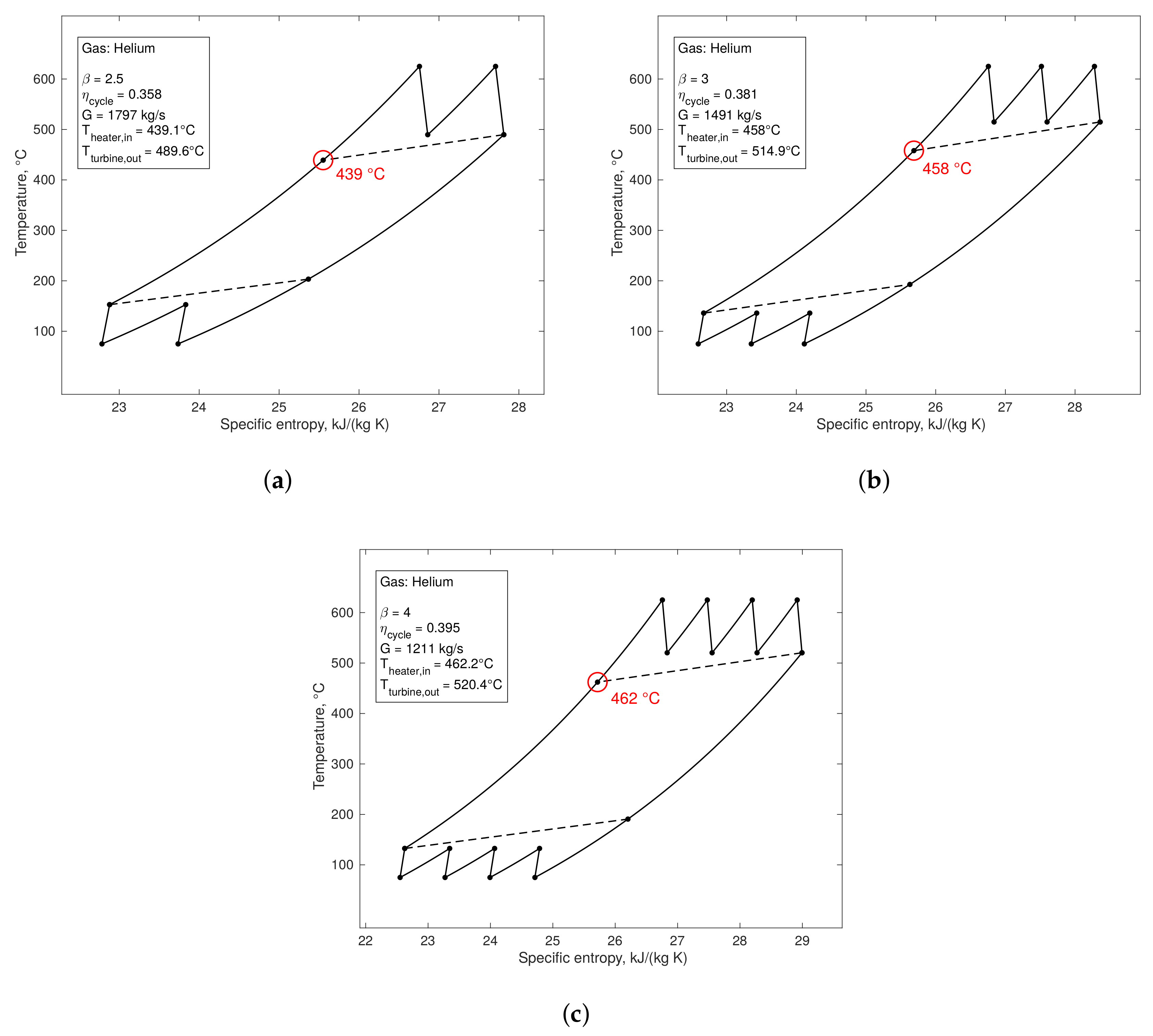
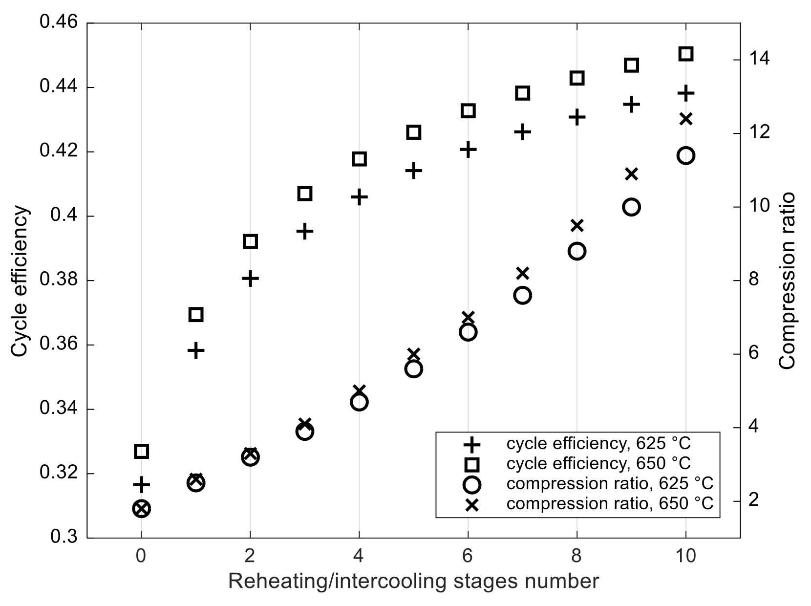
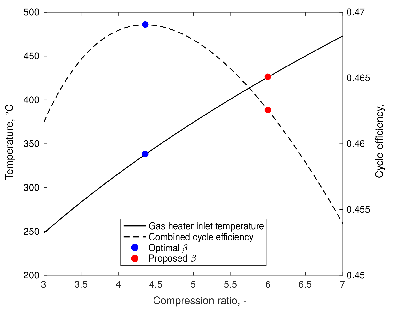
The analysis we performed provided a preliminary design of the energy conversion system. The considered thermodynamic cycles allow a sensible efficiency improvement with respect to the performance of conventional light water reactors. In the temperature range typical of the molten salt fast reactor, the supercritical steam cycle shows the best performance, with achievable cycle efficiencies in line with state-of-the-art steam power plants. The helium cycle suffers from relatively low cycle temperatures, showing worse efficiencies (around 40%). Even though increasing the number of stages should allow for better efficiency, the introduction of several reheating stages is unrealistic, so that with the adopted reference parameters, cycle efficiencies higher than 40% are hardly achievable. Furthermore, the incremental efficiency improvement decreases as stages are added. Thermodynamic performance could be further degraded, should the technological feasibility of pure helium gas turbines impose the adoption of different working fluids. The combined cycle also suffers the limitations imposed by the heat source, and suggests intermediate performance for applications of this kind.
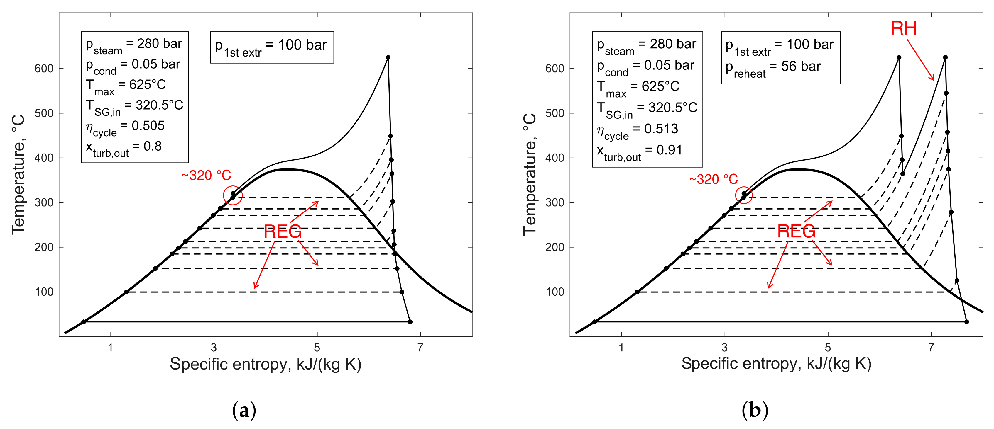
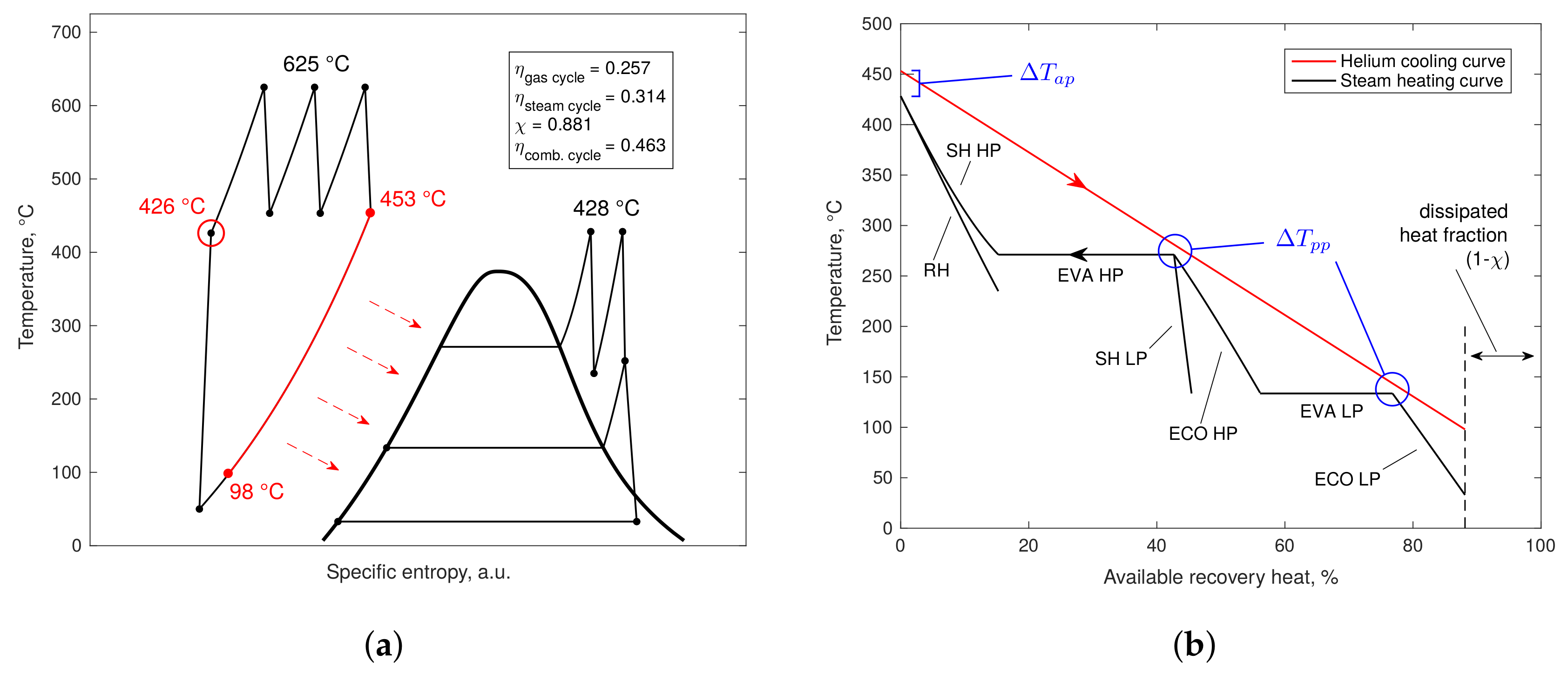
The results highlight the critical issue of molten salt freezing within the secondary heat exchangers, due to the relatively low inlet temperatures of the working fluids in the case of a water/steam cycle. Feedwater inlet temperatures of modern steam plants reach values not higher than about 320 °C, leading to severe issues in the design of the steam generators. The adoption of state-of-the-art steam technology would thus pose severe technical limitations due to the freezing temperatures of molten salts. Gas cycles, on the other hand, by operating with compressible fluids and with a high degree of regeneration, can reach inlet temperatures around 450 °C, ensuring better compatibility with the freezing points of the intermediate salts. The helium/steam combined cycle ensures gas inlet temperatures which are more similar to the ones of simple gas cycles. This aspect, in combination with the intermediate thermal efficiencies shown, makes its employment for molten salt applications promising.
Further study will be needed to assess the overall plant efficiency, and the sensitivity to system parameters such as reactor or intermediate circuit temperatures. Parameter sensitivity and optimisation constitutes, in fact, a critical tool in the design of the MSFR plant, given the complex feedback relationship between thermal design and other crucial reactor design aspects, such as neutronics and dynamics. A more detailed analysis of secondary heat exchangers is also needed, as the freezing issue appears as one of the most limiting factors in the overall design of the plant. Mitigation of risks related to freezing is relevant not only to the MSFR, but also to other industrial applications of molten salts, such as concentrating solar power (CSP) [25]. Other salt compositions, such as chlorine-based ones, might offer better possibilities of overcoming such limitations thanks to lower melting points. Alternative solutions such as supercritical CO2 cycles [26] could be considered as well for future investigations.
Other peculiar aspects of MSRs have not been considered in this analysis, which might, however, affect the choice of the heat conversion technology and the design of related subsystems. One major issue is represented by the production, migration and removal of tritium within molten salt mixtures. Most of salt mixtures considered for MSR applications produce tritium under irradiation due to the presence of lithium, which is often used to reduce the melting points. Even though the enrichment in 7Li has been proposed to mitigate tritium production, its buildup, migration and release to the environment still represent a serious challenge. The fact that heat exchangers present the largest surface area fraction of a reactor, and the temperature differences between the intermediate circuit and the heat sink suggest that preferential buildup may occur in the working fluid of the energy conversion system [27]. This might offer an effective trapping and removal strategy when closed cycles are adopted. In the cases of steam cycles, however, contamination of water would make the separation task particularly challenging, and alternative tritium control strategies would be preferred—e.g., trapping in the intermediate salt or use of migration barriers. Despite being out of the scope of this work, tritium control must therefore be taken into account in the design of the energy conversion system and is a relevant subject for future studies.

Author Contributions

Conceptualisation, A.C.; investigation, A.D.R. and S.L.; supervision, F.G., G.L., S.L., X.W. and A.C.; writing—original draft, A.D.R.; writing—review and editing, A.D.R., F.G., G.L., S.L., X.W. and A.C. All authors have read and agreed to the published version of the manuscript.

Funding

This project has received funding from the EURATOM research and training programme 2014–2018 under grant agreement number 661891.

Conflicts of Interest

The authors declare no conflict of interest.

Disclaimer

The content of this paper does not reflect the official opinion of the European Union. Responsibility for the information and/or views expressed herein lies entirely with the authors.

References

  1. Generation IV International Forum (GIF). Annual Report 2019. 2019. Available online: https://www.gen-4.org/gif/jcms/c_119025/gif-2019-annual-report (accessed on 14 December 2020).
  2. Luzzi, L.; Cammi, A.; Di Marcello, V.; Fiorina, C. An approach for the modelling and the analysis of the MSR thermo-hydrodynamic behaviour. Chem. Eng. Sci. 2010, 65, 4873–4883. [Google Scholar] [CrossRef]
  3. Di Ronco, A.; Cammi, A.; Lorenzi, S. Preliminary analysis and design of the heat exchangers for the Molten Salt Fast Reactor. Nucl. Eng. Technol. 2020, 52, 51–58. [Google Scholar] [CrossRef]
  4. Fiorina, C.; Lathouwers, D.; Aufiero, M.; Cammi, A.; Guerrieri, C.; Kloosterman, J.L.; Luzzi, L.; Ricotti, M.E. Modelling and analysis of the MSFR transient behaviour. Ann. Nucl. Energy 2014, 64, 485–498. [Google Scholar] [CrossRef]
  5. Tsiklauri, G.; Talbert, R.; Schmitt, B.; Filippov, G.; Bogoyavlensky, R.; Grishanin, E. Supercritical steam cycle for nuclear power plant. Nucl. Eng. Des. 2005, 235, 1651–1664. [Google Scholar] [CrossRef] [Green Version]
  6. Zhou, L.; Xu, G.; Zhao, S.; Xu, C.; Yang, Y. Parametric analysis and process optimization of steam cycle in double reheat ultra-supercritical power plants. Appl. Therm. Eng. 2016, 99, 652–660. [Google Scholar] [CrossRef]
  7. Stępczyńska-Drygas, K.; Łukowicz, H.; Dykas, S. Calculation of an advanced ultra-supercritical power unit with CO2 capture installation. Energy Convers. Manag. 2013, 74, 201–208. [Google Scholar] [CrossRef]
  8. Li, D.; Wang, J. Study of supercritical power plant integration with high temperature thermal energy storage for flexible operation. J. Energy Storage 2018, 20, 140–152. [Google Scholar] [CrossRef]
  9. No, H.C.; Kim, J.H.; Kim, H.M. A review of helium gas turbine technology for high-temperature gas-cooled reactors. Nucl. Eng. Technol. 2007, 39, 21–30. [Google Scholar] [CrossRef] [Green Version]
  10. Olumayegun, O.; Wang, M.; Kelsall, G. Closed-cycle gas turbine for power generation: A state-of-the-art review. Fuel 2016, 180, 694–717. [Google Scholar] [CrossRef]
  11. Bhargava, R.K.; Bianchi, M.; De Pascale, A.; Negri di Montenegro, G.; Peretto, A. Gas Turbine Based Power Cycles—A State-of-the-Art Review. In Challenges of Power Engineering and Environment; Cen, K., Chi, Y., Wang, F., Eds.; Springer: Berlin/Heidelberg, Germany, 2007; pp. 309–319. [Google Scholar] [CrossRef]
  12. Kehlhofer, R.; Hannemann, F.; Stirnimann, F.J.; Rukes, B. Combined-Cycle Gas & Steam Turbine Power Plants, 3rd ed.; PennWell: Tulsa, OK, USA, 2009. [Google Scholar]
  13. Dempsey, L.; Forsberg, C.; Dolan, T.J. Electricity production. In Molten Salt Reactors and Thorium Energy; Woodhead Publishing: Duxford, UK, 2017; pp. 13–28. [Google Scholar] [CrossRef]
  14. McDonald, C.F. Power conversion system considerations for a high efficiency small modular nuclear gas turbine combined cycle power plant concept (NGTCC). Appl. Therm. Eng. 2014, 73, 82–103. [Google Scholar] [CrossRef]
  15. Jaszczur, M.; Rosen, M.A.; Śliwa, T.; Dudek, M.; Pieńkowski, L. Hydrogen production using high temperature nuclear reactors: Efficiency analysis of a combined cycle. Int. J. Hydrog. Energy 2016, 41, 7861–7871. [Google Scholar] [CrossRef]
  16. Gerardin, D.; Allibert, M.; Heuer, D.; Laureau, A.; Merle, E.; Seuvre, C. Design Evolutions of Molten Salt Fast Reactor. Proc. of the International Conference on Fast Reactors and Related Fuel Cycles: Next Generation Nuclear Systems for Sustainable Development (FR17). IAEA, 2018. Available online: https://www.iaea.org/publications/13414/fast-reactors-and-related-fuel-cycles-next-generation-nuclear-systems-for-sustainable-development-fr17 (accessed on 14 December 2020).
  17. Safety Assessment of the Molten Salt Fast Reactor. Available online: http://samofar.eu (accessed on 14 December 2020).
  18. Capelli, E.; Beneš, O.; Konings, R. Thermodynamic assessment of the LiF–ThF4–PuF3–UF4 system. J. Nucl. Mater. 2015, 462, 43–53. [Google Scholar] [CrossRef]
  19. Beneš, O.; Konings, R.J.M. Thermodynamic properties and phase diagrams of fluoride salts for nuclear applications. J. Fluor. Chem. 2009, 130, 22–29. [Google Scholar] [CrossRef]
  20. Beneš, O.; Konings, R.J.M. Molten Salt Reactor Fuel and Coolant. In Comprehensive Nuclear Materials; Konings, R.J.M., Ed.; Elsevier: Amsterdam, The Netherlands, 2012; pp. 359–389. [Google Scholar]
  21. Moran, M.J.; Shapiro, H.N.; Boettner, D.D.; Bailey, M.B. Fundamentals of Engineering Thermodynamics; Wiley: Hoboken, NJ, USA, 2018. [Google Scholar]
  22. Zvorykina, A.; Gupta, S.; Peiman, W.; Pioro, I.; Fialko, N. Current Status and Future Applications of Supercritical Pressures in Power Engineering. In Proceedings of the 20th International Conference on Nuclear Engineering (ICONE), Anaheim, CA, USA, 30 July–3 August 2012; pp. 285–300. [Google Scholar] [CrossRef]
  23. Pioro, I. Application of Supercritical Pressure in Power Engineering: Specifics of Thermophysical Properties and Forced-Convective Heat Transfer. In Supercritical Fluid Technology for Energy and Environmental Applications; Anikeev, V., Fan, M., Eds.; Elsevier: Boston, MA, USA, 2014; pp. 201–233. [Google Scholar] [CrossRef]
  24. Zhao, H.; Peterson, P.F. Multiple reheat helium Brayton cycles for sodium cooled fast reactors. Nucl. Eng. Des. 2008, 238, 1535–1546. [Google Scholar] [CrossRef]
  25. Bonk, A.; Sau, S.; Uranga, N.; Hernaiz, M.; Bauer, T. Advanced heat transfer fluids for direct molten salt line-focusing CSP plants. Prog. Energy Combust. Sci. 2018, 67, 69–87. [Google Scholar] [CrossRef]
  26. Syblik, J.; Vesely, L.; Entler, S.; Stepanek, J.; Dostal, V. Analysis of supercritical CO2 Brayton power cycles in nuclear and fusion energy. Fusion Eng. Des. 2019, 146, 1520–1523. [Google Scholar] [CrossRef]
  27. Forsberg, C.W.; Lam, S.; Carpenter, D.M.; Whyte, D.G.; Scarlat, R.; Contescu, C.; Wei, L.; Stempien, J.; Blandford, E. Tritium Control and Capture in Salt-Cooled Fission and Fusion Reactors: Status, Challenges, and Path Forward. Nucl. Technol. 2017, 197, 119–139. [Google Scholar] [CrossRef] [Green Version]
Figure 1. Simplified scheme of the molten salt fast reactor plant. The primary salt acts both as a distributed heat source and as a coolant. An intermediate molten salt loop is also foreseen for safety reasons.
Sustainability 12 10497 g001
Figure 2. Simplified scheme of a steam plant: RH = reheater, REG = regenerator(s), HP/IP/LP = high/intermediate/low pressure.
Sustainability 12 10497 g002
Figure 3. Simplified scheme of a closed gas cycle plant: RH = reheater, IC = intercooler, REG = regenerator, HP/LP = high/low pressure.
Sustainability 12 10497 g003
Figure 4. Simplified scheme of a gas/steam combined cycle plant: HRSG = heat-recovery steam generator, Q ˙ i n = thermal input of the combined cycle.
Sustainability 12 10497 g004
Figure 5. T-s diagrams of the proposed steam cycles (a) without reheating and (b) with reheating. p s t e a m / p c o n d / p r e h e a t / p 1 s t e x t r = evaporation/condensation/reheating/first extraction pressure, RH = reheater, REG = regenerators. Other symbols are defined in Table 5.
Sustainability 12 10497 g005
Figure 6. T-s diagrams of the proposed helium cycles with 1 (a), 2 (b) and 3 (c) reheating/intercooling stages with maximum gas temperature of 625 °C. Symbols are defined in Table 6.
Sustainability 12 10497 g006
Figure 7. Helium cycle efficiency and optimal compression ratio β as functions of n R H = n I C .
Sustainability 12 10497 g007
Figure 8. Results of the proposed helium/steam combined cycle: (a) T-s diagram and (b) HRSG temperature curves. SH = superheater, RH = reheater, EVA = evaporator, ECO = economiser, HP/LP = high/low pressure. Other symbols are defined in Table 7.
Sustainability 12 10497 g008
Figure 9. Combined cycle efficiency and gas heater inlet temperature vs. gas cycle compression ratio β .
Sustainability 12 10497 g009
Table 1. Main MSFR reference design parameters and constraints.
QuantityUnitValue
Core power outputMW3000
No. of primary loop sectors-16
Int. heat exch. heat transfer rateMW187.5
Core outlet temperature ( T h , i n )°C775
Core inlet temperature ( T h , o u t )°C675
Int. loop maximum temperature ( T c , o u t )°Cvariable
Int. loop minimum temperature ( T c , i n )°Cvariable
Table 2. Steam cycle design parameters.
QuantityUnitValue
HP turb. section pressurebar280
IP turb. section pressurebar56
LP turb. section pressurebar11.2
Condensation pressurebar0.05
Primary steam temperature°C625
Reheated steam temperature°C625
Add. extraction pressuresbar[100, 70, 35, 20, 15, 5, 1]
HP turb. section efficiency ( η T , H P )-0.90
IP turb. section efficiency ( η T , I P )-0.92
LP turb. section efficiency ( η T , L P )-0.87
Pumps efficiency ( η P )-0.85
Table 3. Helium cycle design parameters.
QuantityUnitValue
Gas maximum temperature°C[625, 650]
Gas minimum temperature°C75
Reheating temperature°C[625, 650]
Reheating stages number ( n R H )-[1, 2, 3]
Gas maximum pressurebar75
Intercooling temperature°C75
Intercooling stages number ( n I C )-[1, 2, 3]
Turbine efficiency ( η G T )-0.90
Compressor efficiency ( η G C )-0.90
Regenerator effectiveness ( ε R E G )-0.85
Table 4. Helium/steam combined cycle design parameters: topping helium cycle and bottoming steam cycle.
QuantityUnitValue
Helium cycle
HP level pressurebar56
LP level pressurebar3
RH pressurebar12
Condensation pressurebar0.05
HP turb. section efficiency ( η T , H P )-0.90
IP turb. section efficiency ( η T , I P )-0.92
LP turb. section efficiency ( η T , L P )-0.87
Pumps efficiency ( η P )-0.85
Approach-point temp. difference ( Δ T a p )°C25
Pinch-point temp. difference ( Δ T p p )°C10
Steam cycle
Gas maximum temperature°C625
Gas minimum temperature°C50
Compression ratio ( β )-6.0
Reheating temperature°C625
Reheating stages number ( n R H )-2
Turbine efficiency ( η G T )-0.90
Compressor efficiency ( η G C )-0.90
Table 5. Main design results of the supercritical steam cycle.
QuantityUnit(a) without RH(b) with RH
Cycle efficiency ( η c y c l e )%50.551.3
SG feedwater inlet temperature ( T S G , i n )°C320.5320.5
Turbine outlet steam quality ( x t u r b , o u t )-0.800.91
Total steam mass flow rate (G)kg s 1 14261142
Table 6. Main design results of the helium closed cycle with maximum gas temperatures of 625 °C and 650 °C.
QuantityUnit1 RH2 RH3 RH
625 °C
Compression ratio ( β )-2.53.04.0
Cycle efficiency ( η c y c l e )%35.838.139.5
Gas heat inlet temp. ( T h e a t e r , i n )°C439.1458.0462.2
Total gas mass flow rate (G)kg s 1 179714911211
650 °C
Compression ratio ( β )-2.53.04.0
Cycle efficiency ( η c y c l e )%36.939.240.7
Gas heat inlet temp. ( T h e a t e r , i n )°C457.2476.7481.0
Total gas mass flow rate (G)kg s 1 173914441174
Table 7. Main design results of the helium/steam combined cycle.
QuantityUnitValue
Combined cycle efficiency ( η c o m b )%46.3
Gas cycle efficiency ( η g a s )%25.7
Steam cycle efficiency ( η s t e a m )%31.4
Heat recovery effectiveness ( χ )%88.1
Gas mass flow ratekg s−11064
Steam mass flow ratekg s−1596
Gas heater inlet temperature ( T h e a t e r , i n )°C426.2
HRSG gas inlet temperature°C453.2
HRSG gas outlet temperature°C97.9
Steam maximum temperature°C428.2
Steam turbine outlet quality-0.93
Publisher’s Note: MDPI stays neutral with regard to jurisdictional claims in published maps and institutional affiliations.

