Article

Influence of the Water Vapour Permeability of Airtight Sheets on the Behaviour of Facade

by
Joaquín Torres-Ramo
,
Purificación González-Martínez
*,
Nerea Arriazu-Ramos
and
Ana Sánchez-Ostiz
Department of Construction, School of Architecture, Building Services and Structures, University of Navarra (UNAV), Calle Universidad, 31009 Pamplona, Spain
*
Author to whom correspondence should be addressed.
Sustainability 2020, 12(24), 10480; https://doi.org/10.3390/su122410480
Submission received: 6 November 2020 / Revised: 8 December 2020 / Accepted: 9 December 2020 / Published: 15 December 2020

Abstract

:
The air-tightness of the thermal envelope of buildings is one of the measures to reduce their energy demands in order to achieve global warming reduction targets. To this end, airtight sheets with different water vapour permeability characteristics are used. The different products studied are highly dispersed in terms of equivalent air thickness values, leading to confusion. After the analysis carried out, it is concluded that all airtight sheets are vapour barriers. To clarify whether or not these sheets are necessary as vapour barriers, a condensation analysis was carried out on 13 different facades for 3 climate zones with severe winters as defined in Spanish regulations. The results reveal that interstitial condensation occurs in only 7 of the 39 case studies, with the traditional facades of brickwork with render causing the greatest problems if the appropriate products are not used. In these cases, airtight sheets with water vapour barrier characteristics must be applied on the interior face of the insulating material. In all other cases (32), the airtight sheets must be permeable to water vapour if it is looked for a more breathable wall to water vapour and a better control of the interior humidity conditions.

1. Introduction

Global society is increasingly aware of the need for a systematic change in all sectors of the economy to reduce the environmental impacts created by human activity and the building sector must take an active part in the change. In Europe, it is responsible for approximately 36% of all CO 2 emissions, and almost 50% of final energy consumption is used in heating and cooling, of which 80% is consumed in buildings [1]. For this reason, the European Directive on the Energy Performance of Buildings (Directive 2010/31/EU) required that all new public buildings should be nearly zero-energy (nZEB) by 2018 and likewise all buildings by the end of 2020 [2]. nZEB refers to buildings which generate the same amount of energy as they consume over a specific period [3]. As will be described below, one of the measures that must be taken to achieve this balance is the infiltration control [4] as it leads to a reduction in heating demand [5].In fact, the Passivhaus Institut [6] understands it as one of the main measures to be taken to minimize heat losses in low-energy buildings [7,8].
The current European Energy Performance of Buildings Directive of 2018/844 sets ambitious targets and commitments for the year 2030 [1]:
-
Reduction of greenhouse gas emissions (40% in 2030 compared to 1990).
-
Increase in the proportion of renewable energy consumed.
-
Energy savings in line with EU-wide ambitions.
-
Improvement of Europe’s energy security, competitiveness and sustainability.
Reducing energy demand firstly requires the implementation of design strategies and control of passive building measures. These include the correct orientation of the building, increasing thermal insulation, reduction of uncontrolled air infiltration, natural ventilation and use of the thermal inertia of the building envelope [9].
Many authors show the energy advantages of a properly sealed enclosure. Meiss et al. quantify the energy impact that air infiltrations have globally. For the cases of the analysis carried out, in buildings located in the northern area of Spain the infiltration are stated as representing between 10.5 and 27.4% of the energy demand in winter [10]. Furthermore, Alfano et al. state that windows may account for up to 40% of the total building energy demand [11]. A similar study carried out in Finland shows that air leaks of a single-family house are responsible for 15–30% of the energy used for heating [12]. The same was found in a study carried out in Spain (Mediterranean climate area and the Canary Islands) in which the effect of infiltration on the demand for heating and cooling is obtained in a comparative manner. This study concludes that the average air infiltration of renewals per hour measured is 8.43 h 1 , and that it has an energy impact of between 2.43 and 16.44 kWh/m 2 ·year on the heating demand and between 0.54 and 3.06 kWh/m 2 ·year on the cooling demand [13].
Due to the importance of air infiltration in energy consumption, different European countries have established regulations to control it: Czech Republic, France, Germany, Ireland, United Kingdom [14] or Spain [15]. Not only regulations, but also environmental certification systems declare the need to limit air infiltration, as is the case with the BREEAM [16], LEED [17] or the Passivhaus Standard [18]. In this area, the most demanding is the Passivhaus standard in which the Air Renewal Rate (n 50 ) for new construction must be less than or equal to 0.6 h 1 [ACH, Air Changes per Hour] [18].
For this reason, it is necessary to obtain as airtight enclosures as possible. Ren et al. showed that infiltration rates could be reduced by about 52% by sealing the main air leakage routes [19]. Different construction solutions can be used to achieve an airtight layer: interior plaster coating, concrete, wood-based panels or specific products such as sheets, membranes and airtight tapes [18]. In a case study carried out on a single-family dwelling in Levante, Spain, in which airtight sheets and strips were used, it was concluded that the losses in the dwelling due to air infiltration are very low, 5.4 kWh/m 2 ·year, as a value of 0.49 h 1 at n 50 was obtained in the Blower Door test. The value obtained was very low in relation to conventional housing in that area where the ACH is between 5 and 7 times higher [20].
The specific products used to achieve an airtight layer must have certain characteristics of breathability or resistance to water vapour that contribute to the appropriate hygrothermal performance of the different facade solutions.
The flow of water vapour that spreads through the different layers of the enclosure can condense when the water vapour contained in the air encounters a surface that is below the dew point temperature, either superficially or interstitially.
The appearance of condensation in the different layers of the building envelope (in the thermal insulation, in the cladding, in the structural components or in the construction joints [21]) depends on the climate, the indoor environment, the characteristics of the materials and the order in which the different layers are laid [22].
If the drying is not fast enough (the maximum accumulated condensation in a year should not exceed the amount evaporated in the same period [15]), high moisture content on the surfaces and inside the components leads to deterioration of the building materials [23], reduces their life and durability [24], leads to excessive maintenance and renovation costs [25], and to additional heat loss [24] due to reduced effectiveness of insulation materials [25]. In addition, the occurrence of condensation and mould growth is harmful to human health [21], so it must be regulated to ensure the health and comfort of the occupants [24].
The elimination of thermal bridges is essential in cold climates because these areas can produce not only heat loss but also condensation and mould growth [23]. Therefore, standards of many European countries limit the thermal transmittance values to prevent condensation in the building envelope and thermal bridges: Czech Republic [26], Ireland [27,28], the United Kingdom [29] and Spain [15].
Some of the condensation problems can be eliminated with the use of specific airtight products since reducing the flow of air through the enclosure decreases the flow of water vapour contained in the air [30,31]. In addition, there is the possibility of water vapour being transferred by diffusion through the airtight sheet [32]. Therefore, the manufacturers of airtight enclosure products provide data on their water vapour resistance properties and equivalent air thickness. However, the values they provide are scattered and the value at which a sheet begins to be or not permeable to water vapour diffusion is not correctly specified. Nor do the regulations give a clear definition of these properties. For this reason, attention must be paid to the water vapour transmission properties of the materials that make up the sheets or membranes [33].
The article focuses on the study of the sheets used as airtight products on the inside of the enclosures and the breathable membranes that are placed on the outside for wind and water resistance. The aim is to find out what water vapour permeability characteristics they must have to perform properly in terms of hygrothermal behaviour, depending on the type of construction of the vertical enclosure in cold weather areas in Spain.

2. Methodology

Firstly, different construction types (Section 2.1) of currently used facades have been analysed, in order to predefined the need for the application of airtight products, vapour barriers, products for wind and water resistance, as well as the most suitable place of installation.
Then a study was carried out of the air-tightness products and wind and water resistance products available on the market from different manufacturers (Section 2.2). Information has been collected on the technical characteristics (dimensional properties, mechanical properties, fire resistance, waterproofing, water vapour transmission) specific to these products. In this way, it has been possible to have a global vision of the necessary and typical performance of these products through a simple statistical analysis based on their average and standard deviation (Section 3.1).
Finally, a condensation analysis has been carried out to see in which cases it is necessary for the airtight sheet to have vapour barrier characteristics. There are two methods for studying condensation: the static method developed in standard UNE EN ISO 13788:2016 [34] and the dynamic method developed in standard UNE EN 15026:2007 [35]. The static method is a simplified procedure, based on the transport of humidity by pure diffusion in a one-dimensional stable state. This method ignores some issues, such as humidity and heat accumulation in the materials, and the capillary transport of liquid water. If all the variables have to be taken into account (influence of solar radiation, incidence of rain on vapour migration and phenomena related to the drying of structures), the dynamic method must be used. However, in this study, to distinguish between cases in which condensation does or does not appear, the static regime can be used, as this method is more conservative for the construction typologies studied [36]. Cascione et al. [36] carried out a study of condensations in different building typologies in two Italian cities using both methods. From this, they found that with the method of the UNE EN ISO 13788:2016 standard, condensations occur in cases that do not occur with the method of the UNE EN 15026:2007 standard. On the other hand, when condensations were obtained with the UNE EN 15026:2007 standard, they always appear with the UNE EN ISO 13788:2016 standard. For this reason, it was decided to use the static method for the condensation study developed in Section 3.2.
In this way, it has been possible to define in which cases, depending on the climatic zone, it is strictly necessary to add the vapour barrier performance to the airtight products and to see the effect of their application on the different construction typologies.

2.1. Facade Construction Typologies

Three types of opaque facades have been established that are susceptible to the use of airtight sheets.
-
Facade 1 (F1): Traditional facades of brickwork with render or external thermal insulation composite (ETICS).
-
Facade 2 (F2): Heavy (brickwork support) and lightweight ventilated facades.
-
Facade 3 (F3): Facades with resistant wood support.
Each type is described in Table 1 in accordance with the layers that compose it, and in Figure 1 the schemes of same may be seen. A code has been assigned to each type of enclosure layer, which will be used hereafter.
For each type of facade construction, the necessary insulation has been calculated to comply with the indicative values of the characteristic parameters of the thermal envelope indicated in the Spanish energy-saving regulations [15]. The analysis has been carried out for three climate zones indicated in that regulation [15]: climate zone C (in Köppen Geigger’s classification this would be Cfa): U ≤ 0.29 W/(m 2 K), climate zone D (in Köppen Geigger’s classification would be Cfb): U ≤ 0.27 W/(m 2 K) and climate zone E (in Köppen Geigger’s classification would be Cfb): U ≤ 0.23 W/(m 2 K). These areas have been chosen because the colder they are, the greater the risk of condensation.
In Figure 1, the airtight products placed on the inner side of the enclosure have been marked in red (VP-AL). They must be vapour barriers when it is necessary to prevent condensation. In blue are indicated the products for wind and water resistance placed on the external face of the main insulation in facades with ventilated air cavity (WL).

2.2. Products for Air-Tightness and Products for Wind and Water Resistance

Sheets, membranes and tapes contribute to the performance of the requirements that a facade must meet, especially those related to hygrothermal aspects, water protection, wind resistance, UV stability and reaction to fire. Therefore, in order to meet these requirements, these products must have a series of technical characteristics: dimensional properties [37], mechanical properties [38,39,40,41], fire resistance [42], waterproofing [43], water vapour transmission [33,44]). These characteristics vary depending on the constructive types, the location of the sheets and what is demanded of them.
In order to define what properties are necessary and to classify the air-tightness products and the wind and water resistance products, a distinction is made between those placed on the inner side of the thermal insulation and those placed on the outer side of the insulation. The products applied on the inside of the building (Figure 2) must be airtight and have an appropriate resistance to water vapour diffusion if condensation may appear in the type used there. For this purpose, airtight sheets and tapes are used to seal all overlaps, connections and penetrations. The products applied on the outside of the building (Figure 3) must have waterproof and windproof properties, since the outer side of the insulation may be exposed to external climatic conditions, as is the case of ventilated cavity facades. In addition, they must have low resistance to water vapour to allow the enclosure to breathe and to avoid the retention of water vapour on the cold side of the insulation which can lead to condensation. For this purpose, sheets known as breathable membranes and tapes are used to seal all overlaps, connections and penetrations.
These sheets and membranes are generally made from plastic components (modified polyethylene, polypropylene felts or fabrics, polyolefins, etc.) and can be reinforced with fibres from other materials. The tapes used for solving singular points, joints between different construction elements and long-term sealing of the sheets and membranes are usually made of polyethylene or polypropylene and additional materials such as acrylic adhesives and silicone coatings.

3. Results

3.1. Analysis of the Characteristics of Products for Air-Tightness and Products for Wind and Water Resistance

A study has been carried out of the materials that make up the products for air-tightness and the products for wind and water resistance that are currently on the market, the technical characteristics, the specifications and the application conditions. The products of four different manufacturers were studied. Table 2 shows the main characteristics of the sheets fitted on the inside of the thermal insulation, vapour check and vapour barrier, and of the sheets fitted on the outside of the thermal insulation, breathable membranes.
Firstly, this study focused on analysing the technical characteristics of the sheets laid on the inside of the thermal insulation. These products must guarantee air-tightness, have a certain resistance value to water vapour and have the optimum mechanical properties to withstand their installation and the potential stresses to which they may be subjected during their service life. As can be seen in Table 2 the name used by manufacturers to describe the products installed on the inside of the thermal insulation is vapour barrier or vapour check. To unify concepts, the definition of the Spanish regulations has been used [45]: “a vapour barrier is an element that has a resistance to vapour diffusion greater than 10 MN·s/g equivalent to 2.7 m 2 ·h·Pa/mg”. Therefore, the water-vapour resistance of each product has been calculated to determine whether or not they are vapour barriers and to make a simple classification of these products. To obtain the water-vapour diffusion resistance (Z p ), the following procedure has been carried out from the expressions in the standard UNE-EN ISO 12572:2018 [33] and the results are shown in Table 3:
1 . Calculation of the water-vapour resistance factor ( μ [-]) from the equivalent air layer thickness value, (S d [m]) and thickness (e [m]) provided by the manufacturers:
s d = e · μ
2 . Obtaining the water-vapour permeability value of air ( δ v a [kg/(m·s·Pa)]) with reference to the partial vapour pressure from Figure 2 of standard UNE-EN ISO 12572:2018 [33] for a given temperature and barometric pressure: T = 23 C and P = 1 atm:
δ v a = 1.952 × 10 10
3 . Calculation of the water-vapour permeability of the material ( δ v [kg/(m·s·Pa)]) with reference to the partial vapour pressure:
μ = δ v a / δ v
4 . Calculation of the water-vapour diffusion resistance (Z p [(m 2 ·s·Pa)/kg]) from the data on the thickness of the sheet (e [m]) provided by the manufacturers:
Z p = e / δ v
5 . Replacement of water-vapour diffusion resistance units (Z p [(m 2 ·h·Pa)/mg]) to compare it with the CTE definition [45]:
Z p = 2.7
As can be seen in Table 3, all types of sheets comply with the definition of the Spanish standard [45].
Next, an analysis was made of the technical characteristics (Table 2) of the sheets used in the typologies with ventilated cavity from the outside of the thermal insulation, which the manufacturers call breathable membranes. These products must be waterproof, permeable to water vapour, wind-resistant and have the optimum mechanical properties to withstand their installation and the possible stresses to which they may be subjected during their useful life.
Once all the data on the technical characteristics of the sheets fitted on the inside and outside of the thermal insulation had been collected (Table 2), a statistical analysis of air thickness and equivalent thickness, S d , based on the mean ( x ¯ ) and standard deviation ( σ ) has been carried out: x ¯ ± σ . With this study it is possible to observe the dispersion and trend of these two characteristics that arise due to the joint analysis of different products and manufacturers.
In this way, the characteristics of two possible “standard sheets” used in the condensation study have been fixed (Section 3.2). Vapour barriers will be referred to as “sheet type A” and breathable membranes will be referred to as “sheet type B”. Therefore, in the study of condensation, “sheet type A” has been used when it has been seen that the appearance of condensation is possible, and “sheet type B” has been used to protect the insulation when typologies with a ventilated cavity have been analysed.
In the case of vapour barriers, “sheet type A”, only the thickness (0.31 ± 0.12 mm) can be left fixed, and must be fixed at the average value: 0.31 mm. On the other hand, it has been considered that the value of S d should be left unfixed due to the high standard deviation obtained (55.00 ± 61.55 m) and the impossibility of predicting the necessary value to avoid the appearance of condensation, before the study of condensation. This characteristic will be fixed after the condensation study at the minimum necessary value from which condensation no longer occurs in the enclosure.
In the case of breathable membranes, “sheet type B”, the thickness (0.52 ± 0.18 mm) that it must have is the average value: 0.52 mm. On the other hand, the value of S d (0.07 ± 0.09 mm) is also fixed at the value of the average: 0.07 m. In “sheet type B”, the main aim is to ensure water and wind resistance. In this case, it can be left fixed at the average value, despite the high standard deviation, since any value in the range contemplated by the manufacturers ensures optimum breathability. Unlike the case of “sheet type A”, in which resistance to the diffusion of water vapour is the main characteristic and must be fixed precisely, depending on the constructive type, because it directly affects the appearance of condensation.

3.2. Study of Condensation

For the calculation of condensation, the data of the indoor and outdoor climatic conditions have been set in advance. As outdoor conditions, the monthly average external temperature (T m ) and relative humidity (HR m ) values of the location of the building are taken from the Spanish regulations [45].
This has been done for the different building types in the three climate zones stated in Section 2.1 in January, the coolest month, choosing a representative city for each area: Barcelona for zone C (T m = 8.8 C y HR m = 73%), Pamplona for zone D (T m = 4.5 C y HR m = 80%) and Burgos for zone E (T m = 2.6 C y HR m = 86%). As indoor conditions, in all cases an indoor temperature of 20 C and a relative humidity of 55% have been used, depending on the classification of hygrometry 3 of the Spanish regulations [45].
The calculation of the condensation has been carried out with the program eCondensa2 [46]. This program is based on the Spanish regulations for the calculation of surface and interstitial condensation [15]. In the case of checking surface condensations, the program compares the inner surface temperature factor, f R s i , and the minimum inner surface temperature factor, f R s i , m i n , for the inner and outer conditions corresponding to the month of January of the locality: Barcelona for zone C (f R s i , m i n = 0.56), Pamplona for zone D (f R s i , m i n = 0.61) and Burgos for zone E (f R s i , m i n = 0.64). Condensation occurs when the internal surface temperature factor, f R s i , is lower than the minimum internal surface temperature factor, f R s i , m i n For interstitial condensation, the program compares the saturation and vapour pressures. Condensation occurs when the vapour pressure is equal to or higher than the saturation pressure. In addition, eCondensa2 uses the standard UNE EN ISO 13788:2016 [34] for the calculation of accumulated condensation (kg/m 2 ·s) to ensure compliance with the indicated Spanish regulation requirement: “In no case can the maximum accumulated condensation in each annual period exceed the amount of evaporation possible in the same period” [15].
Firstly, a condensation simulation was carried out without using any type of sheeting. In this way, it has been possible to observe that the features strictly required by the products used for air-tightness also had an adequate water-vapour resistance factor to prevent the appearance of condensation. In all other cases, the airtight products had this function only. The results of the cases in which condensation may occur for each climate zone in January appear in Table 4.

3.2.1. Facade 1—Traditional Facade

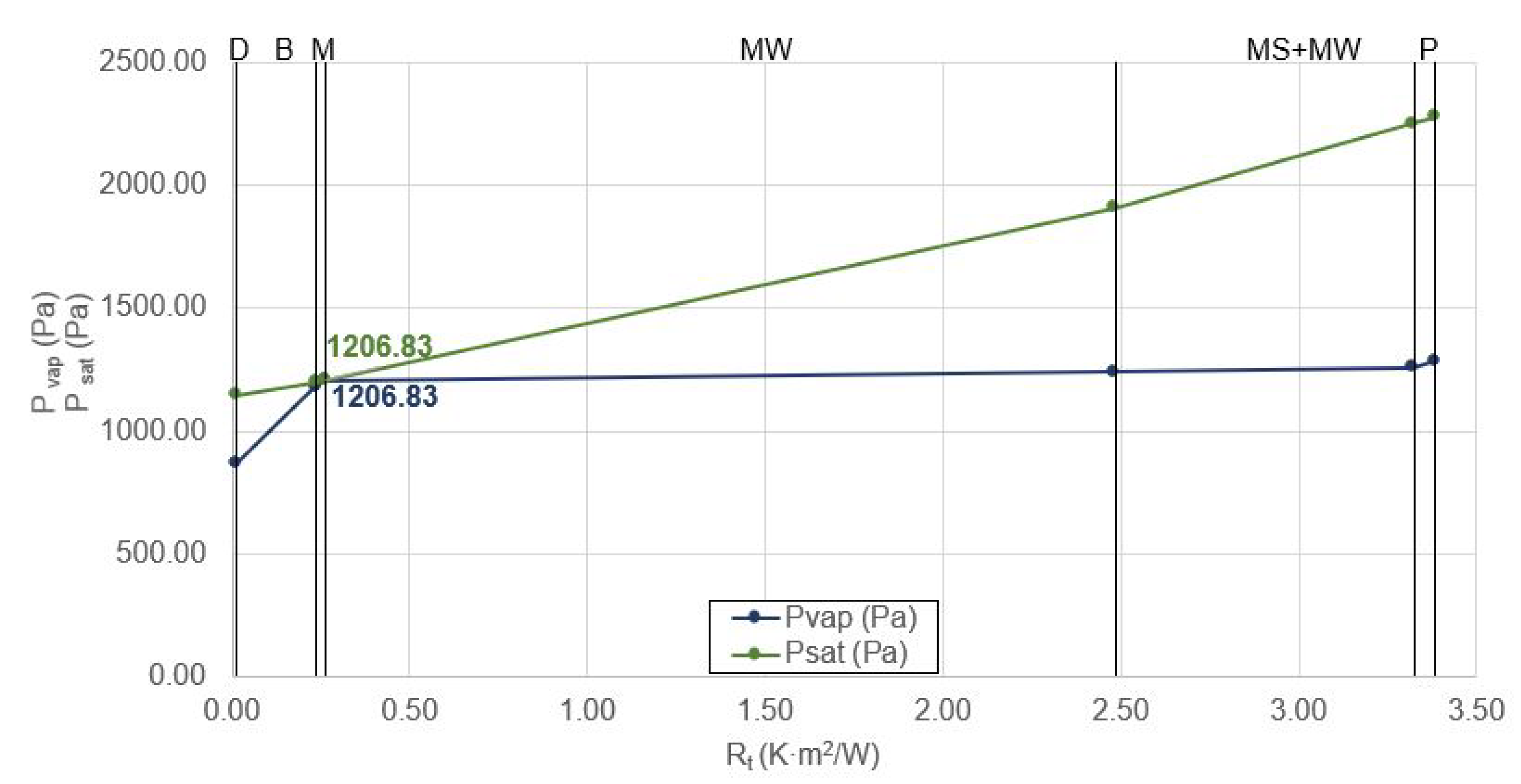
Condensation occurs in each of the three climatic zones in the brickwork with render type (F1.1) in which mineral wool is used as the main insulation. In this case, there is no surface condensation, since the temperature factor of the inner surface f R s i is higher than the minimum temperature factor of the inner surface f R s i , m i n (0.93 > 0.56). However, interstitial condensation occurs between the mortar layer (M) and the mineral wool insulation layer (MW) as the vapour pressure and the saturation pressure are equalised. The accumulated condensation between both layers is 0.076 kg/m 2 ·s and may occur inside the insulation (MW). Figure 4 shows the study for zone C, a less cold climate zone, as an example.
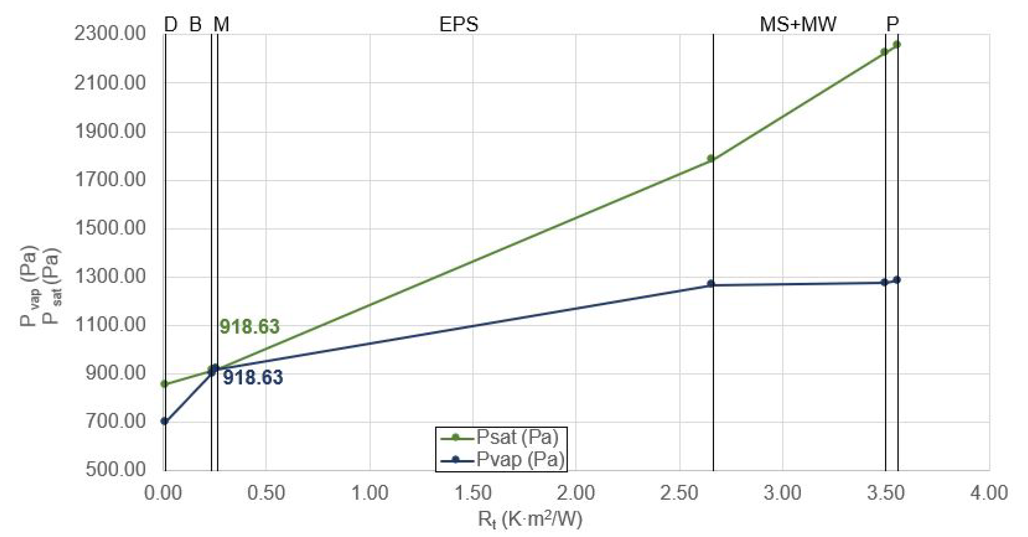
For the brickwork with render type in which EPS is used as the main insulation (F1.2), condensation only occur in climate zones D and E. In this case, no surface condensation occurs because the temperature factor of the inner surface f R s i is higher than the minimum temperature factor of the inner surface f R s i , m i n (0.93 > 0.61). However, interstitial condensation occurs between the mortar layer (M) and the insulation layer (EPS) as the vapour pressure and the saturation pressure are equalised. The accumulated condensation between the two layers is 0.009 kg/m 2 , and it may even occur inside the insulation (EPS). Figure 5 shows the study for zone D, as an example.
Finally, the types incorporating an external thermal insulation system (ETICS) have been analysed. In both cases studied, no surface or interstitial condensation occurred. Figure 6 shows the result obtained for the F1.3 typology which uses ETICS mineral wool, in the E zone, the coldest climatic zone, as an example.

3.2.2. Facade 2—Ventilated Facade

In the typology of heavy (brickwork support) and lightweight ventilated facades, no condensation has occurred in any case. The result obtained for type F2.1 is shown below. Figure 7 shows the study for zone E, the coldest climate zone, as an example.

3.2.3. Facade 3—Wooden Facade

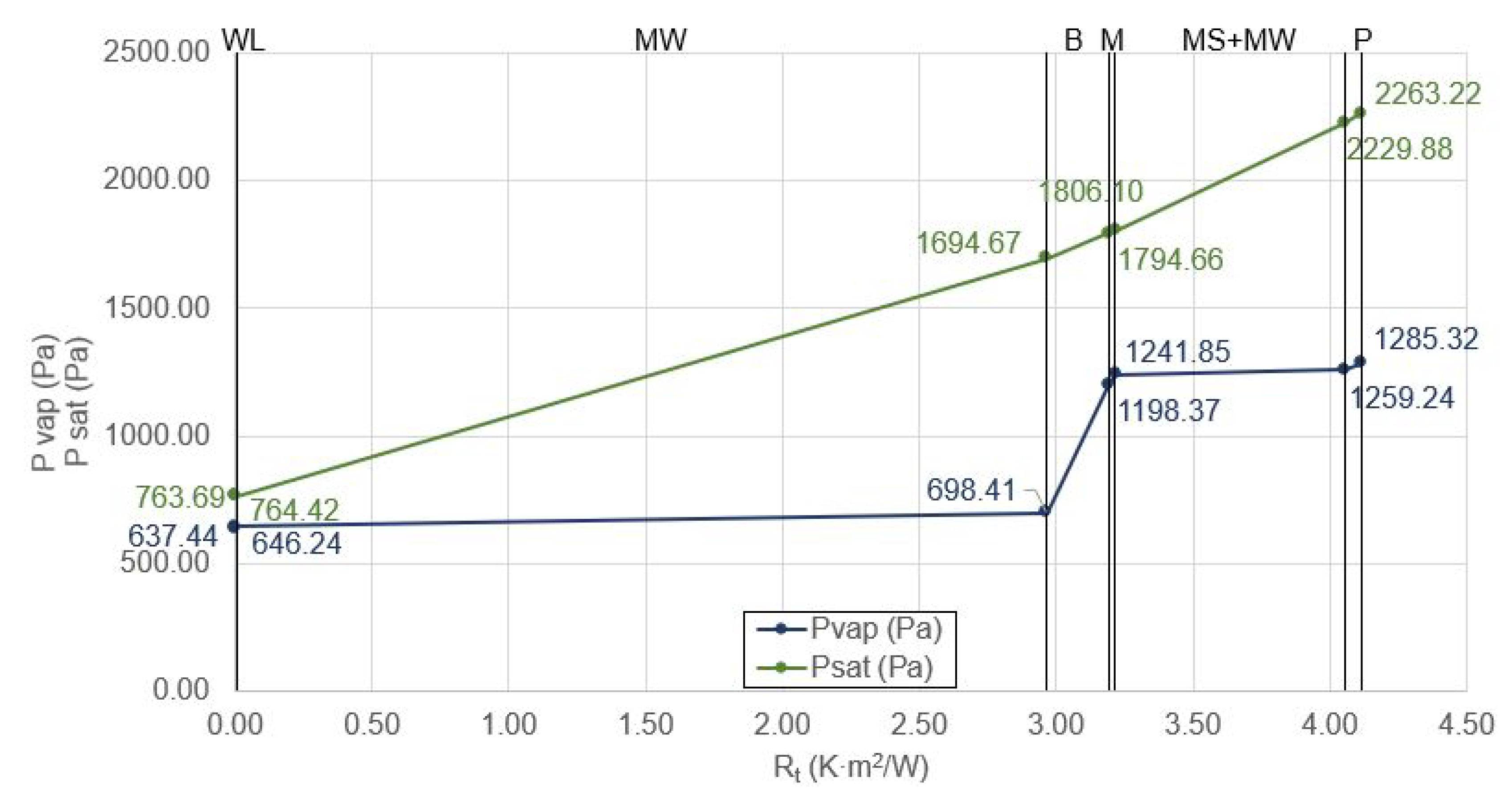
Condensation has been found only in type F3.6 (timber frame with mineral wool insulation and OSB board on the outside) in climate zones D and E where mineral wool is used as the main insulation. In this case, no surface condensation occurs as the inner surface temperature factor f R s i is higher than the minimum inner surface temperature factor f R s i , m i n (0.93 > 0.61). However, interstitial condensation occurs between the mortar layer (M) and the mineral wool insulation layer (MW) as the vapour pressure and the saturation pressure are equalised. The accumulated condensation between both layers is 2.13 kg/m 2 ·s and may occur inside the insulation (MW). Figure 8 shows the study for zone D, as an example.
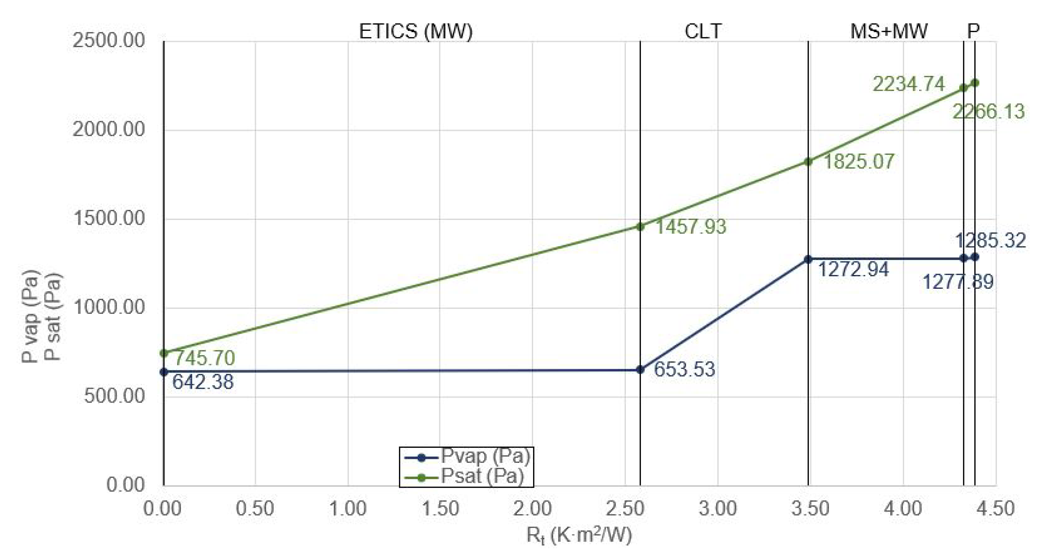
In the remaining wood types studied, no condensation occurred. Figure 9 shows the result obtained for type F3.3 for zone E, a colder climate zone, as an example
Once the typologies in which condensation can occur had been determined, tests were carried out with the different sheets currently on the market. It has been observed that by fitting different sheets with different values of μ and from different manufacturers, condensation is avoided, for a wide range of μ values, and compliance with condensation requirements is achieved. Therefore, for the typologies in which condensation was found, the minimum μ value has been calculated from which condensation is no longer observed. For this purpose, “sheets type A” have been used when it has been seen that condensation is possible, and “sheets type B” have been used for typologies with ventilated cavity. As commented in Section 3.1, in the case of “sheets type A”, the S d value was not fixed so that it could be modified during the condensation study depending on the specific needs of each enclosure. In the case of finding condensation, the value of μ of the “sheets type A” was increased in eCondensa2 until the condensation disappeared. Table 5 shows the results of the resistance properties to water vapour, μ and S d , that the “sheets type A” must have when placed in the types where condensation may appear. Once the values of μ and S d that “sheets type A” must have to avoid condensation have been determined, it must be checked whether they comply with the definition of vapour barrier in the Spanish regulations [45]. Table 5 shows the results obtained using the same calculation method as explained in Section 3.1:

4. Discussion

The analysis of the airtight products shows that the thickness varies between 0.15 mm and 0.57 mm (0.31 ± 0.12 mm). The values obtained for S d have a very high standard deviation (55.00 ± 61.55 m) since the values of this property vary between 2 and 200 m. According to the definition in the Spanish regulations [45], all of these airtight sheets are vapour barriers, and although manufacturers differentiate between vapour check and vapour barrier, the limits between these are not clear. Analysing the values supplied by the different manufacturers, the following ranges can be established as a function of S d : vapour check 2 m ≤ S d ≤ 100 m; vapour barrier: 5 m ≤ S d ≤ 1500 m. Therefore, this differentiation leads to confusion for two reasons: the use of different nomenclature for products that are used to control water-vapour diffusion and the use of different classification ranges for the sheets, together with a great spread of values.
From the analysis of the products for wind and water resistance, breathable membranes, it has been found that the thickness varies between 0.3 mm and 1 mm (0.52 ± 0.18 mm). The equivalent air layer thickness varies between 0.02 m and 0.15 m (0.07 ± 0.09 m). Despite the high dispersion that can be seen in this type of product, it is less relevant than in the case of vapour barriers since any value in the range contemplated ensures adequate breathability for its position on the external face of the insulation within a ventilated cavity.
On the basis of the above, the characteristics of two standard sheets have been defined for use in condensation analysis: “type A sheet” for cases in which condensation is studied (interior airtight sheets that require or do not require vapour barrier properties) and “type B sheet” for cases of breathable membranes on facades with ventilated cavity (F2). The “type A sheet” has a thickness of 0.31 mm and an equivalent thickness of air that remains free to be fixed in the condensation study, and the “type B sheet” has a thickness of 0.57 mm and an equivalent thickness of air of 0.07 m. The analysis of condensation carried out on the types under study shows that in no case does condensation occur on the surface and only in 7 of the 39 cases studied is there a risk of interstitial condensation.
The typologies that belong to the category of “Facade 1—traditional” are those that present the greatest problems. In addition, it should be noted that where mineral wool is the main insulation (F1.1), the appearance of condensation occurs even in zone C, the least cold of the three climatic zones studied. When EPS is used (F1.2), it only occurs in zones D and E, and it does not occur at all in any of the climatic zones if ETICS is used (F1.3 y F1.4). This is due to the fact that the water-vapour resistance factor is higher for EPS, with μ = 20 being the value used for the analysis, although there are EPS isolates that may reach values of μ = 100 [47]. Finally, when ETICs are used on this type of facade, no condensation occurs since the thermal insulation is on the outside and the greatest temperature drop occurs on the outside of the enclosure where the vapour pressure is low.
In none of the types belonging to the category “Facade 2—ventilated” has condensation been found. In these cases the ventilated cavity itself is responsible for evaporating any water vapour that may pass through the enclosure [48], and therefore the type B sheet is very permeable o water vapour.
Finally, in the typologies belonging to the category “Facade 3—wood” interstitial condensation only occurs for the F3.6 typology in climate zones D and E. This type uses a wood framework with mineral wool insulation and OSB boards on the outside as a resistant element. Therefore, in this case, condensation occurs because an element with a high water vapour resistance factor has been placed on the outside, contradicting the basic principle of placing materials with higher μ on the inside of the enclosure: the water vapour resistance factors will gradually decrease from the inside to the outside [32,49].
Later, the values of equivalent air thickness, S d , for the air-tightness sheets of the 7 construction typologies where condensation occurs have been calculated and compared with the definition of a vapour barrier in the Spanish regulations. The values obtained range from 0.1 m to 3.9 m and only the highest value in the range (S d = 3.9 m) meets the definition of a vapour barrier. Therefore, in most typologies it would be enough to regulate the diffusion of water vapour to a much lesser degree than is provided by the airtight sheets on the market or what is defined by Spanish regulations as a vapour barrier. Potential condensation can be avoided at the same time as promotion of the drying mechanisms of the enclosure itself [50,51]. Encouraging the breathability of enclosures is important as vapour barriers can lead to a high accumulation of indoor humidity when there is inadequate ventilation and can result in problems with the building materials and in respiratory problems for the inhabitants [52]. In this way, the demand for ventilation could be reduced while preserving hygrothermal comfort [53].

5. Conclusions

Guaranteeing the air-tightness of the enclosures makes it possible to reduce the energy demand for both heating and cooling. Recent studies of nZEB buildings consider the air-tightness of the envelope an important point to meet the requirements of energy demand. One way to achieve this is by placing airtight sheets on the inside of the thermal insulation of the enclosure. When the enclosures present a risk of condensation, these sheets must have a high resistance to water-vapour diffusion. Otherwise, it is not necessary. Furthermore, in the case of ventilated facades, it is necessary to place a breathable membranes, products for the wind and water resistance, towards the outside of the insulating material.
Airtight products on the market have been studied: 14 air-tightness products, vapour barriers and vapour checks, that are placed on the inside of the thermal insulation and 20 products for the wind and water resistance, breathable membranes, that are placed on the outside of the thermal insulation inside ventilated facades. These 14 interior sheets analysed are classified as vapour barriers in accordance with the definition of the Spanish regulations, despite the great dispersion of the values provided by the manufacturers (S d = 55.00 ± 61.55 mm). All the membranes placed on the outside, despite the dispersion of values observed (§ d = 0.07 ± 0.09 mm), are perfectly breathable.
It has been found that interstitial condensation occurs in 7 of the 39 typologies of facades studied: 13 typologies (Traditional Facade, Ventilated Facade and Wooden Facade) in 3 climatic zones. Only in one of the 7 cases (traditional brickwork facades with render and mineral wool as the main insulation, F1.1, in climate zone E) it is necessary for the airtight sheet to be a vapour barrier. In the other 6 cases it is sufficient for the sheet used to regulate the diffusion of water vapour. Therefore, it is not strictly necessary that in all cases where condensation occurs, the airtight sheet should be a vapour barrier, even though this is the only solution offered by the manufacturers on the market, and the same applies to cases where no condensation occurs. In this way, the wall is more permeable to water vapour and the interior humidity conditions are better regulated.
This study shows the different missions that the air-tightness products and the breathable membranes fulfill and what is their arrangement within the construction typology. Products with higher S d values (air-tightness products) must be placed towards the inside of the insulating material while products with lower S d (breathable membranes) values must go towards the outside of the insulating material. In this way, there is a gradual decrease in S d values from the inside of the insulating material to the outside. The wrong arrangement of the products within the enclosure can lead to the production of condensation or poor performance of the enclosure.

Author Contributions

Introduction, P.G.-M., J.T.-R., A.S.-O. and N.A.-R.; Methodology-Facade construction typologies, P.G.-M. and A.S.-O.; Methodology-Products for air-tightness and products for wind and water resistance, J.T.-R. and N.A.-R.; Results-Analysis of the characteristics of products for airtightness and products for wind and water resistance, P.G.-M., J.T.-R. and N.A.-R.; Results-Study of condensation, A.S.-O., J.T.-R. and N.A.-R.; Discussion, P.G.-M., J.T.-R., A.S.-O. and N.A.-R.; Conclusions, P.G.-M., J.T.-R., A.S.-O. and N.A.-R. All authors have read and agreed to the published version of the manuscript.

Funding

This research received no external funding

Conflicts of Interest

The authors declare no conflict of interest.

References

  1. EU. Directive 2018/844/EU of the European Parliament and of the Council of 30 May 2018 Amending Directive 2010/31/EU on the Energy Performance of Buildings and Directive 2012/27/EU on Energy Efficiency; EU: Brussels, Belgium, 2018. [Google Scholar]
  2. European-Commission. Nearly Zero-Energy Buildings. Available online: https://ec.europa.eu/energy/topics/energy-efficiency/energy-efficient-buildings/nearly-zero-energy-buildings_en?redir=1 (accessed on 10 January 2020).
  3. Sun, Y. Sensitivity analysis of macro-parameters in the system design of net zero energy building. Energy Build. 2015, 86, 464–477. [Google Scholar] [CrossRef]
  4. Poza-Casado, I.; Cardoso, V.E.; Almeida, R.M.; Meiss, A.; Ramos, N.M.; Padilla-Marcos, M.Á. Residential buildings airtightness frameworks: A review on the main databases and setups in Europe and North America. Build. Environ. 2020, 2020, 107221. [Google Scholar] [CrossRef]
  5. Attia, S.; Eleftheriou, P.; Xeni, F.; Morlot, R.; Ménézo, C.; Kostopoulos, V.; Betsi, M.; Kalaitzoglou, I.; Pagliano, L.; Cellura, M.; et al. Overview and future challenges of nearly zero energy buildings (nZEB) design in Southern Europe. Energy Build. 2017, 155, 439–458. [Google Scholar] [CrossRef]
  6. Passivhaus Institut. The Independent Institute for Outstanding Energy Efficiency in Buildings. Available online: https://passivehouse.com/02_informations/01_whatisapassivehouse/01_whatisapassivehouse.htm (accessed on 8 December 2020).
  7. Passivhaus Institut. Building Envelope. Available online: https://passipedia.org/planning/thermal_protection (accessed on 8 December 2020).
  8. Peper, S. Untersuchung der Dauerhaftigkeit von Gebäudeluftdichtheitskonzepten; Passivhaus Institut: Darmstadt, Germany, 2015. [Google Scholar]
  9. Sadineni, S.B.; Madala, S.; Boehm, R.F. Passive building energy savings: A review of building envelope components. Renew. Sustain. Energy Rev. 2011, 15, 3617–3631. [Google Scholar] [CrossRef]
  10. Meiss, A.; Feijó-Muñoz, J. The energy impact of infiltration: A study on buildings located in north central Spain. Energy Effic. 2015, 8, 51–64. [Google Scholar] [CrossRef]
  11. D’Ambrosio Alfano, F.R.; Dell’Isola, M.; Ficco, G.; Palella, B.I.; Riccio, G. Experimental air-tightness analysis in mediterranean buildings after windows retrofit. Sustainability 2016, 8, 991. [Google Scholar] [CrossRef] [Green Version]
  12. Jokisalo, J.; Kurnitski, J.; Korpi, M.; Kalamees, T.; Vinha, J. Building leakage, infiltration, and energy performance analyses for Finnish detached houses. Build. Environ. 2009, 44, 377–387. [Google Scholar] [CrossRef]
  13. Feijó-Muñoz, J.; Pardal, C.; Echarri, V.; Fernández-Agüera, J.; de Larriva, R.A.; Calderín, M.M.; Poza-Casado, I.; Padilla-Marcos, M.Á.; Meiss, A. Energy impact of the air infiltration in residential buildings in the Mediterranean area of Spain and the Canary islands. Energy Build. 2019, 188, 226–238. [Google Scholar] [CrossRef]
  14. REHVA-Journal. REHVA Journal 03/2018—Building and Ductwork Airtightness Requirements in Europe. Available online: https://www.rehva.eu/rehva-journal/chapter/building-and-ductwork-airtightness-requirements-in-europe (accessed on 17 January 2020).
  15. Código Técnico de la Edificiación. Documento Básico HE Ahorro de Energía-2019. Available online: https://www.codigotecnico.org/DocumentosCTE/AhorroEnergia.html (accessed on 20 March 2020).
  16. BREEAM ES NUEVA CONSTRUCCIÓN. Edificios no Residenciales. Manual Técnico 2015. Available online: https://breeam.es/manuales-tecnicos/#286-290-wpfd-breeam-es-nueva-construccion (accessed on 23 January 2020).
  17. LEED. Air Infiltration U.S. Green Building Council-2008. Available online: https://www.usgbc.org/credits/homes/v2008/eac3 (accessed on 23 January 2020).
  18. Pokorny, W.; Zelger, T.; Torghele, K. Passivhaus-Bauteilkatalog: Neubau/Details for Passive Houses: New Building; IBO-Austrian Institute for Building and Ecology GmbH: Basel, Switzerland, 2018; ISBN 978-3-0356-1686-6. [Google Scholar]
  19. Ren, Z.; Chen, D. Estimation of air infiltration for Australian housing energy analysis. J. Build. Phys. 2015, 39, 69–96. [Google Scholar] [CrossRef]
  20. Echarri-Iribarren, V.; Sotos-Solano, C.; Espinosa-Fernández, A.; Prado-Govea, R. The Passivhaus Standard in the Spanish Mediterranean: Evaluation of a House’s Thermal Behaviour of Enclosures and Airtightness. Sustainability 2019, 11, 3732. [Google Scholar] [CrossRef] [Green Version]
  21. Nguyen, C.K.; Teodosiu, C.; Kuznik, F.; David, D.; Teodosiu, R.; Rusaouen, G. A full-scale experimental study concerning the moisture condensation on building glazing surface. Build. Environ. 2019, 156, 215–224. [Google Scholar] [CrossRef] [Green Version]
  22. Budaiwi, I.; Abdou, A. The impact of thermal conductivity change of moist fibrous insulation on energy performance of buildings under hot–humid conditions. Energy Build. 2013, 60, 388–399. [Google Scholar] [CrossRef]
  23. Evola, G.; Margani, G.; Marletta, L. Energy and cost evaluation of thermal bridge correction in Mediterranean climate. Energy Build. 2011, 43, 2385–2393. [Google Scholar] [CrossRef]
  24. Asphaug, S.K.; Kvande, T.; Time, B.; Peuhkuri, R.H.; Kalamees, T.; Johansson, P.; Berardi, U.; Lohne, J. Moisture control strategies of habitable basements in cold climates. Build. Environ. 2020, 169, 106572. [Google Scholar] [CrossRef]
  25. Harriman, L.G.; Grimes, C.; Hart, K.Q.; Hodgson, M.; Thi, L.C.N.; Offermann, F.; Rose, W.; Harriman, L.G.; Zhang, J. Position Document on Limiting Indoor Mold and Dampness in Buildings; ASHRAE: Atlanta, GA, USA, 2018; p. 22. [Google Scholar]
  26. Vyhláška č. 268/2009 Sb, VYHLÁŠKA ze dne 12. Srpna 2009 o Technických Požadavcích na Stavby. 2009. Available online: https://www.zakonyprolidi.cz/cs/2009-268 (accessed on 14 December 2020).
  27. Technical Guidance Document L—Dwellings, Conservation of Fuel and Energy—Dwellings. 2011. Available online: https://www.housing.gov.ie/housing/building-standards/tgd-part-l-conservation-fuel-and-energy/technical-guidance-document-l-2 (accessed on 14 December 2020).
  28. Technical Guidance Document L—Building Other than Dwellings, Conservation of Fuel and Energy—Building Other than Dwellings. 2011. Available online: https://www.housing.gov.ie/housing/building-standards/tgd-part-l-conservation-fuel-and-energy/technical-guidance-document-l-3 (accessed on 14 December 2020).
  29. The Building Regulations, Site Preparation and Resistance to Contaminants and Moisture. 2010. Available online: https://www.gov.uk/government/publications/site-preparation-and-resistance-to-contaminates-and-moisture-approved-document-c (accessed on 14 December 2020).
  30. Essah, E.A.; Sanders, C.H.; Baker, P.; Kalagasidis, A.S. Condensation and moisture transport in cold roofs: Effects of roof underlay. Build. Res. Inf. 2009, 37, 117–128. [Google Scholar] [CrossRef]
  31. Ala-Kotila, P.; Vainio, T.; Laamanen, J. The Influence of Building Renovations on Indoor Comfort—A Field Test in an Apartment Building. Energies 2020, 13, 4958. [Google Scholar] [CrossRef]
  32. Hens, H. Applied Building Physics. Ambient Conditions, Building Performance and Material Properties; Ernst & Sohn University of Louven: Louven, Belgium, 2016; ISBN 978-3-433-03147-6. [Google Scholar]
  33. UNE-EN ISO 12572. Hygrothermal Performance of Building Materials and Products—Determination of Water Vapour Transmission Properties—Cup Method. ISO 12572:2016; Asociación Española de Normalización y Certificación: Madrid, Spain, 2018. [Google Scholar]
  34. UNE-EN ISO 13788. Hygrothermal Performance of Building Components and Building Elements—Internal Surface Temperature to Avoid Critical Surface Humidity and Interstitial Condensation—Calculation Methods. ISO 13788:2012; Asociación Española de Normalización y Certificación: Madrid, Spain, 2016. [Google Scholar]
  35. UNE-EN 15026. Hygrothermal Performance of Building Components and Building Elements—Assessment of Moisture Transfer by Numerical Simulation; Asociación Española de Normalización y Certificación: Madrid, Spain, 2007. [Google Scholar]
  36. Cascione, V.; Marra, E.; Zirkelbach, D.; Liuzzi, S.; Stefanizzi, P. Hygrothermal analysis of technical solutions for insulating the opaque building envelope. Energy Procedia 2017, 126, 203–210. [Google Scholar] [CrossRef]
  37. UNE-EN 1849-2. Flexible Sheets for Waterproofing. Determination of Thickness and Mass per Unit Area. Part 2: Plastic and Rubber Sheets; Asociación Española de Normalización y Certificación: Madrid, Spain, 2019. [Google Scholar]
  38. UNE-EN 12310-1. Flexible Sheets for Waterproofing. Part 1: Bitumen Sheets for Roof Waterproofing. Determination of Resistance to Tearing (Nail Shank); Asociación Española de Normalización y Certificación: Madrid, Spain, 2000. [Google Scholar]
  39. UNE-EN 12310-2. Flexible Sheets for Waterproofing. Determination of Resistance to Tearing. Part 2: Plastic and Rubber Sheets for Roof Waterproofing; Asociación Española de Normalización y Certificación: Madrid, Spain, 2001. [Google Scholar]
  40. UNE-EN 12311-1. Flexible Sheets for Waterproofing. Part 1: Bitumen Sheets for Roof Waterproofing. Determination of Tensile Properties; Asociación Española de Normalización y Certificación: Madrid, Spain, 2000. [Google Scholar]
  41. UNE-EN 12311-2. Flexible Sheets for Waterproofing. Determination of Tensile Properties. Part 2: Plastic and Rubber Sheets for Roof Waterproofing; Asociación Española de Normalización y Certificación: Madrid, Spain, 2013. [Google Scholar]
  42. UNE-EN 13501-1. Fire Classification of Construction Products and Building Elements—Part 1: Classification Using Data from Reaction to Fire Tests; Asociación Española de Normalización y Certificación: Madrid, Spain, 2019. [Google Scholar]
  43. UNE-EN 1928. Flexible Sheets for Waterproofing. Bitumen, Plastic and Rubber Sheets for Roof Waterproofing. Determination of Watertightness; Asociación Española de Normalización y Certificación: Madrid, Spain, 2000. [Google Scholar]
  44. UNE-EN 1931. Flexible Sheets for Waterproofing. Bitumen, Plastic and Rubber Sheets for Roof Waterprofing. Determination of Water Vapour Transmission Properties; Asociación Española de Normalización y Certificación: Madrid, Spain, 2019. [Google Scholar]
  45. Código Técnico de la Edificiación. DA DB-HE/2-Comprobación de Limitación de Condensaciones Superficiales e Intersticiales en los Cerramientos-2013. Available online: https://www.codigotecnico.org/DocumentosCTE/AhorroEnergia.html (accessed on 20 March 2020).
  46. Aurea Consulting—DesignBuilder España. eCondensa2. Available online: https://ecoeficiente.es/econdensa2/ (accessed on 25 March 2020).
  47. Código Técnico de la Edificiación. Catálogo de Elementos Constructivos-2010. Available online: https://www.codigotecnico.org/index.html (accessed on 20 March 2020).
  48. Nizovtsev, M.; Letushko, V.; Borodulin, V.Y.; Sterlyagov, A. Experimental studies of the thermo and humidity state of a new building facade insulation system based on panels with ventilated channels. Energy Build. 2020, 206, 109607. [Google Scholar] [CrossRef]
  49. Bogdanović, V.; Milanović, D. Design of the vapor diffusion characteristics of the exterior facing of the facade thermal insulation systems. Facta Univ. Ser. Archit. Civ. Eng. 2003, 2, 349–356. [Google Scholar] [CrossRef] [Green Version]
  50. Lstiburek, J. Understanding Vapor Barriers; Building Sciences Corporation: Westford, MA, USA, 2011; p. 29. [Google Scholar]
  51. Bastien, D.; Winther-Gaasvig, M. Influence of driving rain and vapour diffusion on the hygrothermal performance of a hygroscopic and permeable building envelope. Energy 2018, 164, 288–297. [Google Scholar] [CrossRef]
  52. Howieson, S. The great Scottish housing disaster: The impacts of feudalism, modernism, energy efficiency and vapour barriers on indoor air quality, asthma and public health. Sustainability 2018, 10, 18. [Google Scholar] [CrossRef] [Green Version]
  53. Toman, J.; Vimmrova, A.; Černỳ, R. Long-term on-site assessment of hygrothermal performance of interior thermal insulation system without water vapour barrier. Energy Build. 2009, 41, 51–55. [Google Scholar] [CrossRef]
Figure 1. Construction typologies of facades.
Sustainability 12 10480 g001
Figure 2. Airtight internal sheets.
Sustainability 12 10480 g002
Figure 3. Breathable external membranes.
Sustainability 12 10480 g003
Figure 4. Facade condensation study F1.1 in climate zone C.
Sustainability 12 10480 g004
Figure 5. Facade condensation study F1.2 in climate zone D.
Sustainability 12 10480 g005
Figure 6. Facade condensation study F1.3 in climate zone E.
Sustainability 12 10480 g006
Figure 7. Facade condensation study F2.1 in climate zone E.
Sustainability 12 10480 g007
Figure 8. Facade condensation study F3.6 in climate zone D.
Sustainability 12 10480 g008
Figure 9. Facade condensation study F3.3 in climate zone E.
Sustainability 12 10480 g009
Table 1. Constructive types of facades studied and thickness of the insulating material calculated according to the climatic zone C, D and E.
Facade Typology *DescriptionThickness ** (cm)
Zone CZone DZone E
F1. TRADITIONAL FACADE
F1.1D + B + M + MW + AL + (MS + MW + P)91013
F1.2D + B + M + EPS + AL + (MS + MW + P)8912
F1.3ETICS(MW) + B + AL + (MS + MW + P)8911
F1.4ETICS (EPS) + B + AL + (MS + MW + P)9912
F2. VENTILATED FACADE
F2.1V/VC + WL + MW + B + M + AL + (MS + MW + P)91012
F2.2V/VC + XPS + B + M + AL + (MS + MW + P)8811
F2.3V/VC + WL + MW + AL + P + (MS + MW + P)101113
F3. WOODEN FACADE
F3.1V/VC + WL + MW + CLT + VP-AL + (MS + MW + P)6710
F3.2V/VC + XPS + CLT + VP-AL + (MS + MW + P)568
F3.3ETICS (MW) + CLT + VP-AL + (MS + MW + P)679
F3.4ETICS (EPS) + CLT + VP-AL + (MS + MW + P)679
F3.5V/VC + WL + MW + T-W + VP-AL + (MS + MW + P)121215
F3.6V/VC + WL + MW + W-T + VP-AL + (MS + MW + P)121215
NOTE *: EXTERNAL SHELL: V (Ventilated Exterior cladding), D (Render), ETICS (External Thermal Insulation Composite Systems); CAVITY: VC (Ventilated Cavity), NV (Non-ventilated Cavity) THERMAL INSULATION: MW (Mineral Wool), EPS (Expanded Polystyrene), XPS (Extruded Polystyrene); RESISTANT ELEMENT: FB (Facing Brick Wall), B (Brick wall), CLT (Cross-Laminated Timber), T-W (Timber Framework with interior wood-based board), W-T (Timber Framework with exterior wood-based board), MS (Metal Substructure); OTHERS: M (Damp-proof mortar), P (Plasterboard), AL (Airtight Layer), VP (Vapour Barrier), WL (Wind and Water Layer). NOTE **: Results of the calculation of the minimum thickness of the main insulation; For all types, the thickness of the inner sheet is 4 cm and it has been calculated that it is composed of 85% insulation and 15% profiling (this will be considered for the calculations in Section 3.1).
Table 2. Technical characteristics of the sheets and membranes of each manufacturer studied.
ManufacturerProduct Type According to Manufacturer *Mass per Unit Area
(g/m 2 )
Thickness
(m)
Equivalent Air Layer Thickness S d (m)Maximum Traction Force [N/50 mm] (MC/DC) **Elongation [%] (MC/DC) **Tear Resistance per Nail [N] (MC/DC) **
AIRTIGHT PRODUCTS
AVapour Check120 ± 100.572210/160 ± 3060/80 ± 15180/220 ± 15
100 ± 100.4220180/120 ± 3065/70 ± 1580/90 ± 15
BVapour Barrier1260.425200/18050/50200/200
C 1000.15107150/150850/850140/140
Vapour Barrier1300.20150220/25010/10170/170
1000.20200230/23015/15110/110
1100.2040220/190150/15155/145
Vapour Check1000.3026150/13050/5080/80
1210.4030220/18047/68160/160
100 ± 100.235160/160 ± 3030/30 ± 15200/200 ± 15
90 ± 100.3320160/160 ± 3030/30 ± 15200/200 ± 15
DVapour Check170 ± 100.27100160/130 ± 3044/25 ± 15- /-
180 ± 100.285490/230 ± 303/6 ± 1560/45 ± 15
90 ± 100.3460180/125 ± 3068/79 ± 15125/110 ± 15
PRODUCTS FOR WIND AND WATER RESISTANCE
ABreathable membrane155 ± 100.750.02300/190 ± 3061/70 ± 15150/190 ± 15
200 ± 100.500.05350/190 ± 3030/70 ± 15200/200 ± 15
160 ± 100.500.14210/205 ± 3055/70 ± 15245/225 ± 15
230 ± 100.580.02210/155 ± 3060/70 ± 15105/140 ± 15
BBreathable membrane1360.500.05282/20465/94181/219
CBreathable membrane750.300.02150/6540/5045/55
900.300.02170/14050/4080/90
1120.400.02250/16550/70115/135
1150.300.05245/12552/57170/190
1350.600.02280/19060/75125/135
1500.500.05315/25061/66255/270
1500.500.05315/25061/66255/270
1500.700.02350/21060/75165/175
1900.600.05375/30550/60250/300
2101.000.15380/42040/45225/210
2100.300.04300/20025/25120/120
2900.500.05550/47534/37305/350
145-0.04240/180 ± 3065/40 ± 15145/185 ± 15
DBreathable membrane220-0.09300/340 ± 3050/60 ± 15200/185 ± 15
240-0.40400/420 ± 30-200/200 ± 15
NOTE *: Manufacturers identify and classify airtight products according to their behaviour with regard to water vapour resistance; NOTE **: MD: Longitudinal/CD: Transversal.
Table 3. Obtention of the vapour resistance of each product to check compliance with the vapour barrier definition.
ManufacturerProduct Type According to Manufacturer δ v (kg/m·s·Pa)Thickness (m) μ (-)S d (m)Z p (m 2 ·h·Pa/mg)Vapour Barrier
AVapour Check5.563 × 10 14 0.000573509.022.840YES
4.099 × 10 15 0.0004247,619.02028.461YES
BVapour barrier1.640 × 10 14 0.0004311,904.857.115YES
C 3.649 × 10 16 0.00015535,000.0107114.199YES
Vapour Barrier2.603 × 10 16 0.00020750,000.0150213.456YES
2.603 × 10 16 0.00020750,000.0200213.456YES
1.073 × 10 15 0.00020182,000.04051.799YES
Vapour Barrier2.251 × 10 15 0.0001586,700.02637.013YES
2.603 × 10 15 0.0004075,000.03042.691YES
1.952 × 10 14 0.0002310,000.057.115YES
4.880 × 10 15 0.0003340,000.02028.461YES
DVapour Check9.760 × 10 16 0.00027200,000.010014.304YES
1.952 × 10 14 0.0002810,000.057.115YES
4.099 × 10 15 0.0004247,619.02028.461YES
Table 4. Construction typology in which the application of a vapour barrier is necessary.
Facade Typology Climate Zones
TypologyZone CZone DZone E
F1. Traditional FacadeF1.1YESYESYES
F1.2NOYESYES
F1.3NONONO
F1.4NONONO
F2.1NONONO
F2. Ventilated FacadeF2.2NONONO
F2.3NONONO
F3. Wooden FacadeF3.1NONONO
F3.2NONONO
F3.3NONONO
F3.4NONONO
F3.5NONONO
F3.6NOYESYES
Table 5. Obtention of the vapour resistance of “sheet type A” for checking compliance with the vapour barrier definition.
TypologyClimate Zone δ v (kg/m·s·Pa)Thickness (m) μ (-)s d (m)Z p (m 2 ·h·Pa/mg)Vapour Barrier
ZONE C5.577 × 10 13 0.000313500.1090.154NO
F1.1ZONE D3.148 × 10 14 0.0003162001.9222.735NO
ZONE E1.549 × 10 14 0.00031126003.9065.558YES
ZONE C------
F1.2ZONE D3.098 × 10 13 0.000316300.1950.278NO
ZONE E3.754 × 10 14 0.0003152001.6122.294NO
ZONE C------
F3.6ZONE D1.027 × 10 13 0.0003119000.5890.838NO
ZONE E4.647 × 10 14 0.0003142001.3021.852NO
Publisher’s Note: MDPI stays neutral with regard to jurisdictional claims in published maps and institutional affiliations.