1. Introduction
Agriculture and forestry are responsible for about six percent of the greenhouse gases (GHG) shares in the EU-27 countries [
1], with transportation in harvesting operations having the greatest environmental impact, with fuel consumption being mostly comparable to expenditures of other resources (motor and hydraulic oil, tires, maintenance, etc.) consumed during these operations [
2].
In order to satisfy the proposed goals for reduction of GHG and other harmful gasses, manufacturers are constantly innovating. The most prominent way of innovating with the aim of reducing emissions is through hybridization and electrification of the driveline, which is also becoming commonplace in the forestry sector, with various machinery, mostly harvesters [
3], showing promising results in terms of fuel savings, lower running costs, and noise level reduction. Hybrid skidders are not yet available on the market, nor has their hybridization been researched in many publications. This presents the main motivation for doing this research. As skidders are essentially specialized forestry tractors equipped with a log pulling winch and other mechanical accessories necessary for logging, modernization efforts applicable to similar off-road vehicles can also be applied to skidders. Many different hybrid powertrain variants can be found in off-road vehicle, such as fuel cell hybrids [
4], hybrid electric vehicles with natural gas compression engines [
5], and a single electric machine power-split hybrid [
6].
According to [
1], the average age of non-road mobile machinery (NRMM) used in agriculture and forestry is over 15 years. These vehicles are rather expensive due to their specialized purpose, so their owners and operators are not likely to purchase a new vehicle, hybrid or electric, due to their high purchase (initial investment) cost, especially if hybridization through retrofitting might be a much less expensive solution to satisfying the reduced emissions and fuel (energy) expenditure constraints.
In that regard, hybridization through retrofitting of existing vehicle powertrains may indeed be a more palatable solution for off-road machinery operators, because it allows for three main advantages compared to traditional vehicles: (i) reduction of harmful particles and gasses, (ii) improved driving performance, and (iii) lower fuel consumption. However, it is paramount to first understand the vehicle purpose and its driving modes to correctly choose a proper hybrid powertrain configuration and, thus, to offer a suitable design of hybridized vehicle powertrains [
7]. To get the most out of the hybrid vehicle, it is also crucial to have an efficient control strategy that will manage power flows between different energy sources (i.e., the internal combustion engine, electrical machines, and the energy storage systems, such as a battery).
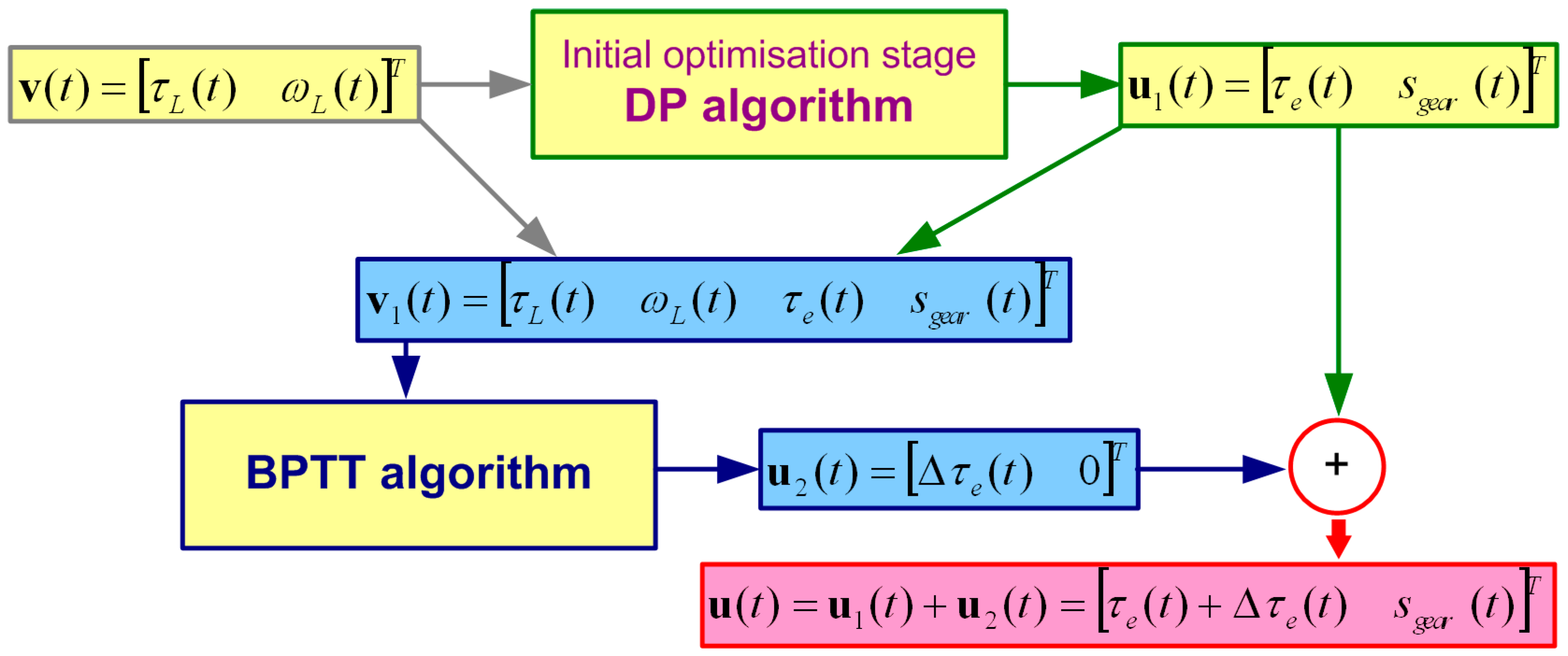
In order to gain these insights, and to find an off-line optimal control law for the hybrid powertrain, this paper proposes the utilization of optimization tools based on the so-called cascade control optimization algorithm [
8], featuring a simplified backward-looking model of the hybrid powertrain. The main hypothesis of this work is that by utilizing the combined approach based on successive optimization by means of dynamic programming (DP) and a back propagation through time (BPTT) gradient-based algorithm, a noticeable improvement in fuel efficiency and greenhouse gases emission can be achieved, compared to the rule-based control previously presented in [
9]. Based on the results of the optimization study conducted herein, conclusions are drawn regarding the potentials for emission reduction and overall fuel (energy) efficiency improvement of hybridized powertrains in a forestry machinery application, along with the estimation of the return of investment period of such a hybridization.
2. Skidder Models Used in Optimization
Simple backward models of conventional and hybrid skidders used for simulation studies were introduced in [
9]. The models are based on a 7200 kg Skidder EcoTrac 120V, which is a heavy-duty forestry tractor used for pulling logs out of forests. It is manufactured by the Hittner company located in the town of Bjelovar, Croatia [
10]. According to the data from reference [
11], over a hundred units of this type are deployed around different forestry estates in Croatia.
Figure 1a shows the main components of a conventional skidder powertrain. The system consists of internal combustion engine (ICE), friction clutches, a ten-speed manual gearbox divided in five low-ratio road transport gears, and five high-ratio working gears, mechanical shafts that transfer power to forward (FD) and rear (RD) differentials and distribute power to all four wheels [
12]. The ICE considered herein is a four-stroke diesel engine type F6L-914, manufactured by Deutz AG from Köln, Germany. It is a naturally-aspirated 6.5 L six-cylinder in-line (straight-six), air-cooled, engine with maximum power rating
Pe of 84 kW at 2300 min
−1 and maximum engine torque
Te of 400 Nm at 1500 min
−1 [
13]. Skidders are also equipped with a double (or single) drum winch used for pulling logs, and a rear-side anchor-protective board, which also provides additional stability during winching operations. In a conventional skidder, the aforementioned winch system is driven by a hydraulic pump propelled by mechanical power from the engine, which may also supply additional hydraulic actuators.
The principal requirement of hybridization is maintaining the performance of the hybrid drive at least equal to that of the conventional one, while minimal modifications to the overall powertrain would also be desirable from a production point of view. In that respect, the maximum loading capabilities of the particular forestry vehicle should also be respected (see e.g., [
14] and the discussion presented therein). A P2 parallel hybrid configuration (shown in
Figure 1b) is proposed herein, which satisfies the predefined driving performance, and also does not require major modifications of the conventional powertrain for its installation [
9]. Thus, the chosen P2 parallel configuration may also be convenient from the standpoint of conventional powertrain retrofitting to its hybrid counterpart. As
Figure 1b shows, the hybrid skidder has an additional electric motor-generator (MG), clutch, and properly sized battery to store sufficient electric energy for the anticipated working cycle. Since improved acceleration, driving comfort, and other requirements typical for passenger vehicles are not crucial for heavy-duty forestry vehicles, introduction of a hybrid powertrain is primarily motivated by the possibility of reduction of fuel consumption and pollutant emissions. In that respect, fuel savings can be achieved by implementing the so-called start-stop functionality, i.e., turning off the main diesel engine when the vehicle is stationary, and using the electric motor to propel the winch hydraulic pump. Other operating regimes, such as those characterized by peak engine torque requirements may also be partially covered by the electric machine torque, such as when hard accelerating and going uphill are necessary. In turn, this may further reduce the fuel consumption, especially if the energy stored within the battery has been obtained by operating the ICE in the vicinity of its fuel-optimal operating point, or during regenerative braking intervals (e.g., during vehicle downhill driving).
2.1. Powertrain Model Components
Detailed hybrid powertrain model components selection and sizing were conducted in [
9]. The electric motor (MG) was chosen to propel the winch hydraulic system since the winch drive is the largest power consumer during stationary operation with the maximum load of 83 kW [
9]. A three-phase synchronous permanent-magnet electrical machine (manufacturer designation AF 130) with nominal torque of 145 Nm and nominal power of 64 kW was chosen in [
15]. Its peak output power of 100 kW can be delivered for up to 60 s, which is considered satisfactory for the particular application. Li-ion cells were chosen for the hypothetical battery energy storage system due to their availability and high gravimetric energy density. The number of cells required (250 cells in particular) was determined based on the electrical power requirements from [
9]. In order to satisfy the rated DC bus voltage requirement of the servomotor power converter (typically 460 V), cells were arranged in parallel-connected series strings, with 125 cells each, thus being able to deliver up to 100 kW from the battery energy storage system. Parameters (such as number
N, energy
E, charge capacity
Q, power rating
Pmax, and mass
mbat) of a single cell [
16] and the proposed battery are given in
Table 1.
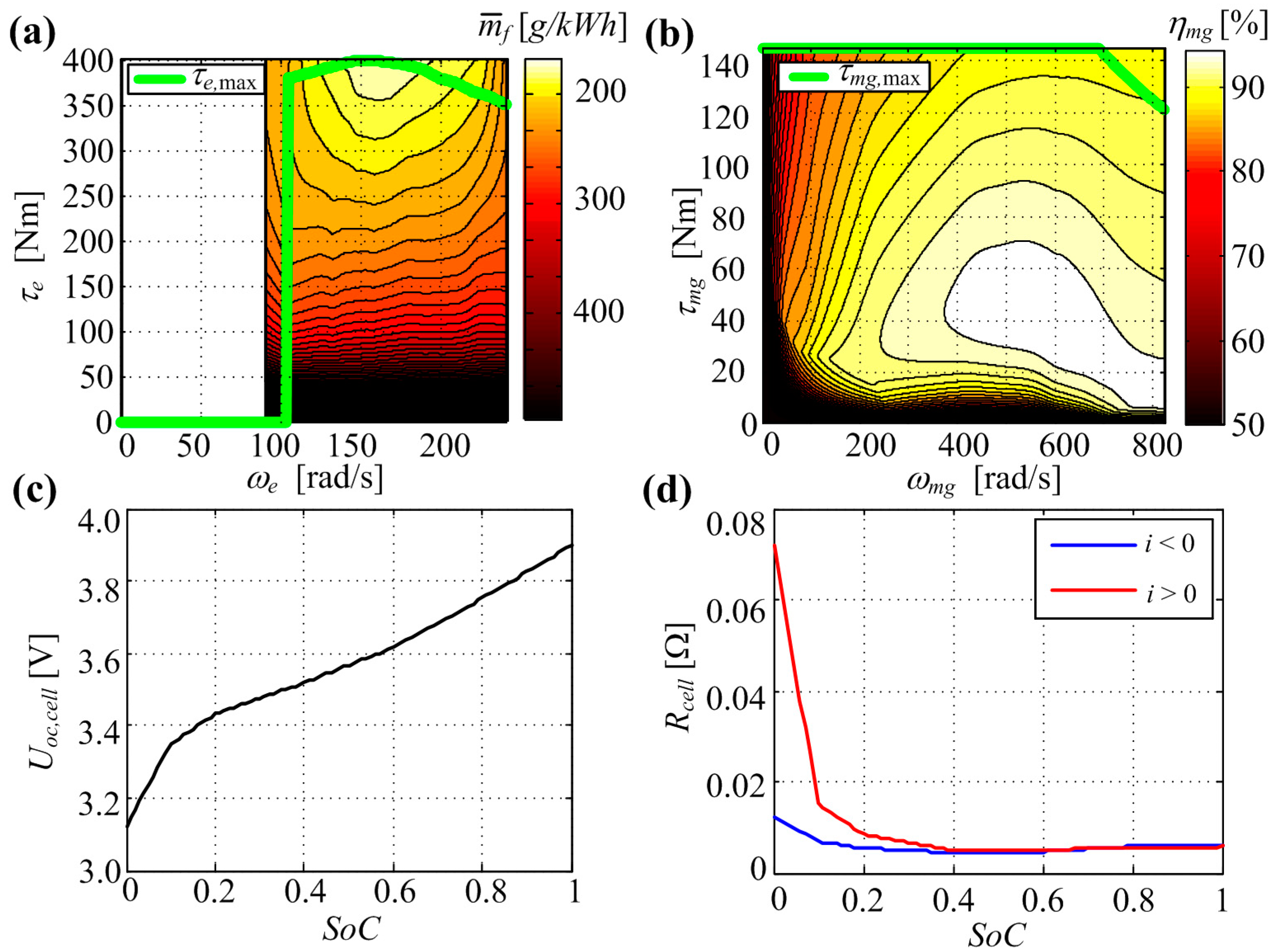
Figure 2 shows the static characteristics (maps) of individual components of the skidder hybrid powertrain from [
9], which are based on engine catalog data from [
13], and electric machine data from [
15]. Battery data were taken from [
16]. The characteristics include an internal combustion engine torque vs. engine speed map with specific fuel consumption as the parameter (
Figure 2a), electric motor torque vs. speed map with efficiency as the parameter, shown in
Figure 2b, and the battery cell open-circuit voltage vs. state-of-charge (
SoC), illustrated in
Figure 2c, and cell internal resistance in
Figure 2d. Green curves in
Figure 2a,b denote the maximum torque curves for particular machines (i.e., internal combustion engine, M/G1 and M/G2 machines, respectively).
Vehicle all-four-wheel traction is achieved through a ten-speed gearbox connected directly to the ICE, comprising five low-ratio and five high-ratio gears. High transmission ratio gears are particularly interesting for this study, because they are used as working gears in forest areas and as such are considered further in this paper. The total transmission ratios for each high-ratio gear setting, transfer case, and differentials are shown in
Table 2.
2.2. Backward-Looking Powertrain Model
In order to reduce the computational load of the optimization algorithm, the backward-looking model structure is commonly used in various optimization studies [
7].
Figure 3 shows the structure of the hybrid skidder backward-looking model, wherein the vehicle wheel angular speed input
ωL is obtained from the vehicle longitudinal velocity
v (defined as time series for the considered driving cycle) according to the following straightforward relationship:
where
r is the effective tire radius.
On the other hand, the related transmission load torque
τL is calculated by using the simplified skidder motion Equation [
17]:
where
Fl is the total load force,
ml is the winch-suspended log weight,
ms is the skidder weight,
α is the terrain slope, and
f,
k, and
μp represent the rolling resistance, load mass distribution, and skidding resistance coefficients, respectively. Rolling resistance
f and skidding resistance
μp are highly dependent on the varying state of the terrain (e.g., muddy, dry or wet ground, soil of rocky terrain). Within the scope of the work presented in this paper, median values (
f = 0.12,
k = 0.48,
μp = 0.51) from the field data [
18] are used herein.
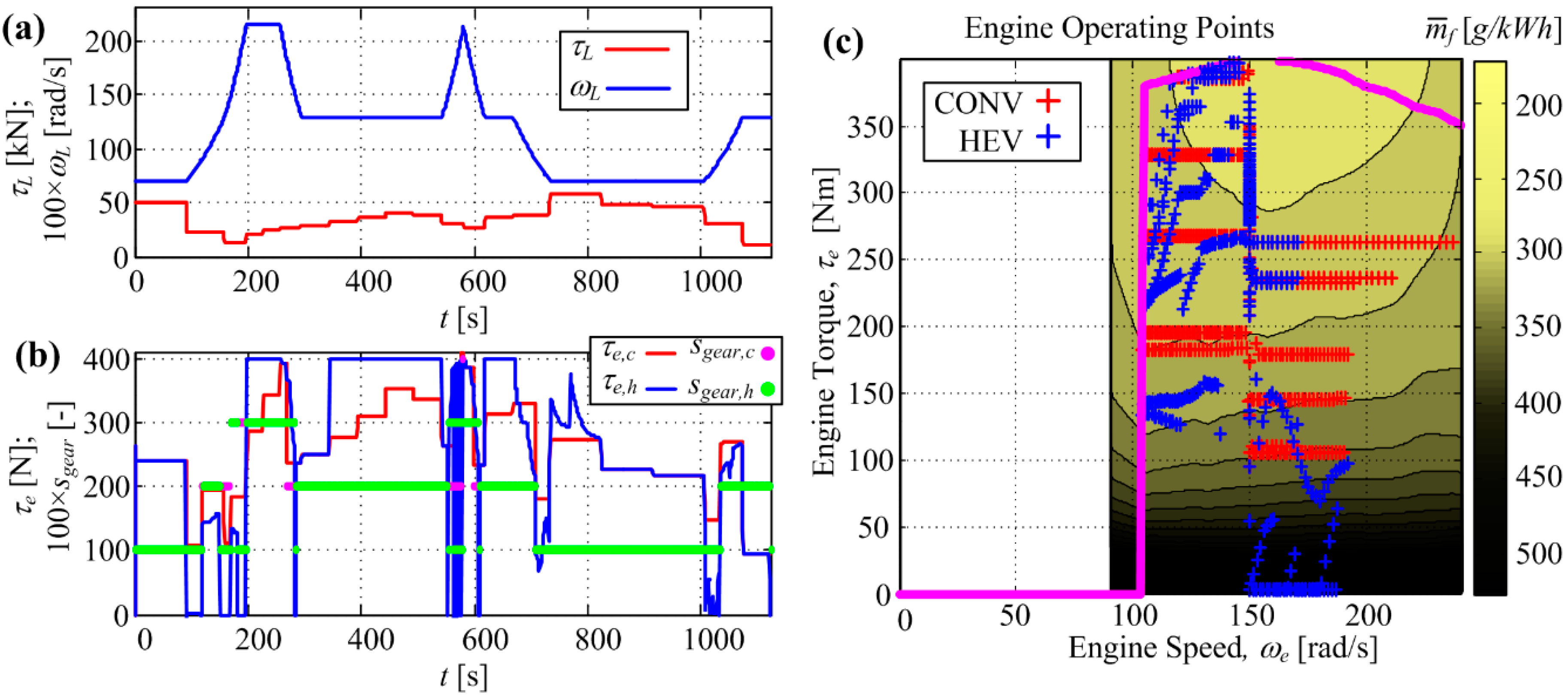
In this particular model, load torque
τL and wheel speed
ωL are the a priori known model inputs. Other powertrain inputs
τe, and
sgear are the ICE torque and the selected gear ratio, respectively, and they represent the control variables to be optimized. Note that in the case of conventional skidders only one discrete
sgear variable is optimized. The mechanical transmission sub-model is described by the “inverted” kinematics equations for each gear as follows:
where in the case of a conventional skidder, the MG torque
τmg and speed
ωmg are omitted from the above equations.
Referring further to
Figure 3, the transmission sub-model output variables
ωe and
τe are fed into the specific fuel consumption map shown in
Figure 2a in order to calculate the engine fuel mass flow:
Similarly, the MG speed and torque variables are fed as inputs into the electric machine efficiency map in
Figure 2b in order to determine the MG electric power output
Pmg which is equal to the battery power
Pbatt in the following way:
where
ηmg is the efficiency of the MG machine. The superscripts
kef is equal to −1 in the case of an electrical machine operating as a motor, while is it is equal to +1 in the case of generator operation.
The battery dynamics model is derived from the equivalent circuit shown in the battery block in
Figure 3, with the following well-known nonlinear differential equation [
19]:
with 0 ≤
SoC ≤ 1 being the battery state of charge, and
Qmax being the battery charge capacity. Within the above battery model, the so-called open-circuit voltage
Uoc is made dependent on the
SoC (
Figure 2c, [
9]). The battery internal resistance
R is also made dependent on the
SoC, with the additional dependence on the current sign, that is current flow direction denoting charging (−1) and discharging (+1), as shown in
Figure 2d.
2.3. Skidder Load Calculations
In order to calculate the time-dependent load vectors (
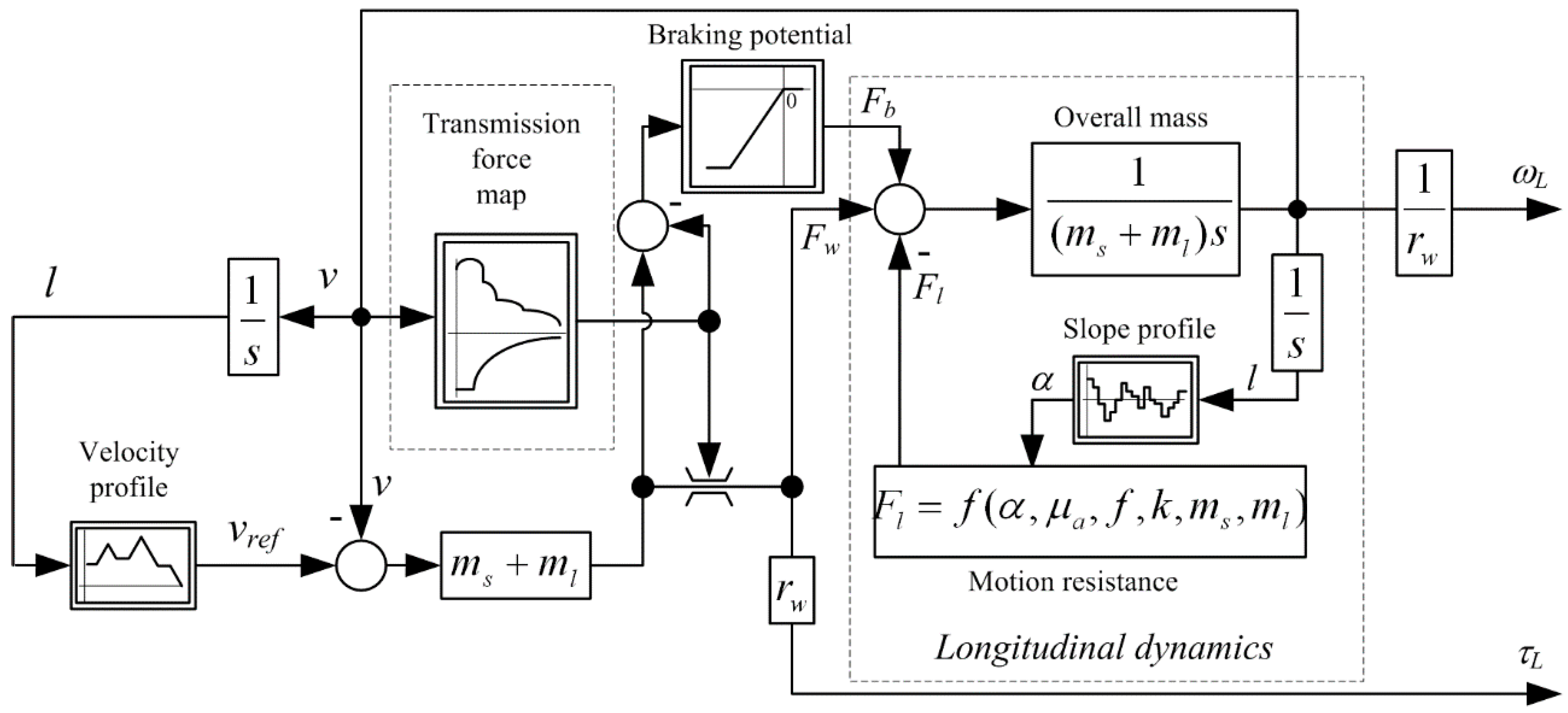
τL, ωL) from the skidder motion profile, a simple vehicle dynamics model including the transmission model, vehicle mass, and variable driveline load related to slope effects and timber pulling weight is proposed herein, and shown in
Figure 4. Reference velocity
vref is compared with actual skidder velocity
v. Velocity difference is fed to the proportional gain term (
ml +
ms) and the required wheel force
Fw is calculated. This force is subject to powertrain limitations, with positive values corresponding to limitations of the ICE engine, and negative values corresponding to limitations of the MG during regenerative braking. These limitations are modeled within the transmission force map as a lookup table. In the case when regenerative braking is not sufficient to provide enough braking force, brakes are activated, resulting in additional negative breaking force
Fb. Skidder acceleration is than calculated from the sum of all forces acting upon the overall mass (i.e., wheel force
Fw, load
Fl, and breaking force
Fb, see summation point in
Figure 4). Since the skidder is represented as a point mass, its overall mass consists of the skidder mass itself
ms and the log mass
ml.
3. Skidder Driving Missions and Load Calculations
Based on an exhaustive literature review, there are no standardized driving cycles for skidders such as those available for road vehicles [
20]. A skidder’s working cycle can be divided into a skid trail phase, landing travel that consists of unloaded and loaded travel, landing and felling site work, and additional allowance time. Felling and landing site work contain forestry operations such as hooking, winching, unhooking, piling, etc. [
21]. In reference [
22] several skidder cycles were generated by using terrain data from internet services (Croatian forestry company „Hrvatske šume“, Zagreb, Croatia and „GPS Visualizer“ free online software with last update from 24.2.2020., created by Adam Schneider, Portland, USA) that consisted of only skid trail travel and winching and known powertrain load parameters available from the literature. Hence, in this paper a single hillside slope from [
9] was chosen for optimization studies, wherein the vehicle travels in both directions with three different hung loads: 0 t, 3 t, and 6 t, with the latter being the maximum load of the winch [
18]. The working cycle studied in this paper will also consist of only skid trail travel and winching. Without real terrain measurements it is impossible to assume skidder working conditions in the rest of the harvesting operations. This presented model can later be easily adjusted and used across the whole working cycle. The cycle studied in this paper presents over 50% of the skidder’s working time [
21] and can be used as a good representation of expected fuel savings.
Reference velocity is calculated by using the vehicle motion equation as the input to determine the ICE speed wherein maximum powertrain torque is achieved, along with the selection of the gear ratio that enables the skidder to haul the particular load. In the case of downhill drive, reference velocity is reduced in order to avoid dangerous overspeed operation of the drive. Considered driving missions are given in
Table 3, where
l is driving distance,
h is elevation, and
vref0,
vref3, and
vref6 are reference velocities for 0, 3, and 6 t of load, respectively.
Logs can be skidded in both uphill and downhill driving scenarios, therefore, two different scenarios were made. In the A scenario, the felling site is located on the higher attitude, above the landing site, and in the B scenario, the felling site is located on the lower attitude, below the landing site. One driving cycle consists of unloaded travel, winching, and loaded travel, and according to [
21], on an average skid trail distance of 900 m it is possible to complete 8.6 cycles in one working day in both A and B scenarios. Average measured load mass is around 4 t [
21], therefore 3 t of logs were pulled in two thirds of the driving scenarios and 6 t were pulled in one third of the driving scenarios. Fuel consumption for the conventional skidder is calculated by using the following expression:
where
is fuel spent in one driving cycle of the conventional vehicle,
is that spent in driving with 0, 3, and 6 t and
for winching.
Expression for the hybrid vehicle is the same as above, but without winching:
6. Results Discussion and Cost Assessments
According to [
24], for very shallow battery depth of discharge (DoD) (10%), the battery cycle life is typically about 15,000 charge/discharge cycles. This life cycle value represents the expected utilization lifetime of the skidder battery before the degradation of its characteristics due to utilization becomes perceptible (i.e., its charge capacity drops below 80% of the nominal value [
25] or its internal resistance increases by 100% [
26]), which typically mandates a complete replacement of the battery energy storage system. The aforementioned 10% SoC charge–discharge cycle approximately corresponds to one skidder’s driving cycle, wherein winching discharges the battery by about 6% of the nominal charge, and the rest (4% of the nominal charge) would be discharged during driving. With that said, it is likely that the battery would last for at least 15,000 driving cycles. Cumulative fuel consumption and fuel cost of the conventional and hybrid skidders are listed in
Table 6. Skidders operate on many different attitudes and terrain slopes (uphill and downhill driving), so the fuel used for final comparison is the mean value of the A2 and B scenarios, which represent one driving cycle used in
Table 6. It is expected that in the battery life span, the hybrid skidder could reduce fuel consumption by 6000 L, which also corresponds to a reduction of CO
2 of 15.9 t and with the current diesel fuel price of 1.086 EUR/L [
27], it translates to savings of 6515 EUR.
Diesel fuel and battery costs can change over time, hence the maximum acceptable battery cost can be estimated as [
16]:
where
and
are total fuel consumed in liters for the conventional and the hybrid skidders, respectively (see
Table 5),
is the number of cycles over one battery life cycle (chosen to be 15,000),
is the proposed battery capacity in kWh, and
is the diesel fuel price in EUR/L.
According to Equation (14), while using data from
Table 3 and taking into account the battery size, diesel fuel costs, and the number of cycles, the battery cost should not exceed 447 EUR/kWh. For that maximum battery cost value, the only savings that can be achieved are in terms of CO
2 reduction.
The average price of an Li-ion battery per kWh in 2019 was 156 EUR [
28]. According to supplier data [
29], the price for a single electromotor is 5000 EUR. Estimated costs of hybrid skidder components are shown in
Table 7. Other accessory components needed for this kind of hybridization (cables, new clutch, etc.) are not included in this calculation.
According to [
30], the average number of operating days in one year for twelve different forest units in Croatia for the aforementioned EcoTrac 120 skidder is 151 days, which translates to 1208 operating hours. With battery and electromotor prices from
Table 7 and diesel prices according to [
27] it is possible to pay off the main hybrid drive components in 13 years and reduce CO
2 emissions by 18.2 t (1.4 t per year). It is worth mentioning that this pay-off time relates only to savings achieved with winching and skid trail driving, where the skidder does 8.6 full cycles in one day as mentioned before. In real life scenarios, the number of skidder’s working days strongly depends on exploitation strategy, weather, work conditions, etc.
If an achieved efficiency improvement of 15.27% can be carried throughout all the skidder’s operations, with average fuel consumption of 10.1 L per hour reported in [
11] and 1208 operating hours in one year, the return of investment period is reduced to 44 months with 4.9 t of CO
2 emissions reduction per year.
As mentioned earlier, there are 121 EcoTrac 120V skidders in Croatia, and by introducing the proposed hybrid system to a large number of skidders, the purchase price of the hybrid components would likely be lower due to bulk purchase discounts [
29], so that the overall fuel savings and CO
2 emission reduction potential can be better utilized.
7. Conclusions
The paper has presented a backward powertrain model of a skidder based on data presented in a previous paper from the same authors. The driving control variables were optimized by means of a cascade optimization approach combining DP and BPTT optimization algorithms in a sequential manner with the goal of minimizing the fuel consumption while satisfying transmission components constraints and the required state-of-charge bounds and boundary conditions. The optimization algorithm showed promising results. For most loads, initial and final SoC were honored, while simultaneously achieving fuel consumption reduction for the particular route. Higher consumption for the hybrid skidder was noticed in scenarios where the battery was recharged during driving. Two different driving scenarios for the case of loaded uphill and downhill drives were defined. Best cases from both these scenarios were used in the further assessment of the hybrid skidder, with their median values showing an efficiency improvement of 15.27%. The proposed novel control variable optimization showed perceptible improvement in terms of fuel savings compared to the rather simple rule-based control presented in the previous paper from the same authors, while also maintaining sustainable battery SoC levels throughout the whole working cycle. In this way, the proposed methodology systematically solves the problem of fuel consumption optimization for the particular skidder hybrid powertrain topology, while also maintaining the battery state-of-charge within prescribed margins. This is beneficial from the standpoint of energy reserve for emergency situations and also from the standpoint of maximization of the useful life of the battery (i.e., by preventing deep battery discharges).
The analysis has also shown that with an approximate battery life of 15,000 cycles it is possible to save 6516 EUR worth in fuel, as well as to achieve proportional reductions of CO2 emissions. With the listed hybrid components prices and average number of the skidder’s operating hours, it is possible to pay off the main hybrid components in 13 years of continuous work under the considered simulation scenario assuming 151 effective 8-hour long workdays, or 44 months if the achieved powertrain efficiency can be carried throughout all the skidder’s operations.
It is worth mentioning that this efficiency improvement refers only to skid trail driving and winching operations. More accurate numbers and results could be obtained if this control variable optimization procedure was carried out throughout the whole skidding process, characterized by additional operating regimes. Therefore, the next step in this research would be to carry out the analysis using accurate real-life recorded terrain data that would contain better resolution of the terrain slope profile and vehicle speed, and actual winch loads encountered in real-life operation.


 ,
, 


