Abstract
This article presents a methodological foundation to design and experimentally test a Model Predictive Controller (MPC) to be applied in renewable source-based microgrids with hydrogen as backup. The Model Predictive Controller has been developed with the aim to guarantee the best energy distribution while the microgrid operation is optimized considering both technical and economic parameters. As a differentiating element, this proposal provides a solution to the problem of energy management in real systems, addressing technological challenges such as charge management in topologies with direct battery connection, or loss of performance associated with equipment degradation or the required dynamics in the operation of hydrogen systems. That is, the proposed Model Predictive Controller achieves the optimization of microgrid operation both in the short and in the long-term basis. For this purpose, a generalized multi-objective function has been defined that considers the energy demand, operating costs, system performance as well as the suffered and accumulated degradation by microgrid elements throughout their lifespan. The generality in the definition of the model and cost function, allows multi-objective optimization problems to be raised depending on the application, topology or design criteria to be considered. For this purpose, a heuristic methodology based on artificial intelligence techniques is presented for the tuning of the controller parameters. The Model Predictive Controller has been validated by simulation and experimental tests in a case study, where the performance of the microgrid under energy excess and deficit situations has been tested, considering the constrains defined by the degradation of the systems that make up the microgrid. The designed controller always made it possible to guarantee both the power balance and the optimal energy distribution between systems according to the predefined priority and accumulated degradation, while guaranteeing the maximum operating voltage of the system with a margin of error less than 1%. The simulation and experimental results for the case study showed the validity of the controller and the design methodology used.
1. Introduction
In general, a smart grid is a concept that comprises an efficient way to manage electricity that uses different technologies and tools to optimize the production and distribution of electricity, pursuing the balance between producers and consumers [1,2].
Specifically, in the case of renewable source-based microgrids with hydrogen as backup (Figure 1 shows the general architecture of a hydrogen-based microgrid), the intelligent management system must be responsible not only for satisfying the load at all times, optimizing production and distribution but it must accomplish pivotal goals in the case of hydrogen systems as lifespan, degradation, costs, operating time and losses [3,4].
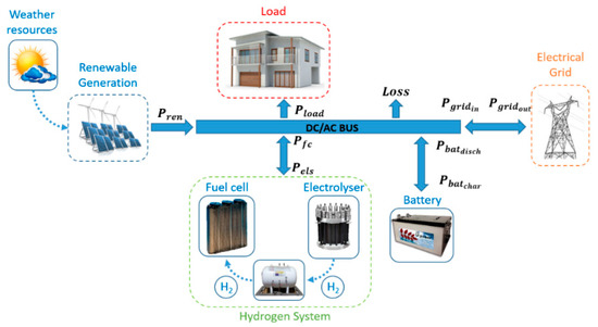
Figure 1.
General architecture and power balance of a renewable source-based microgrid with hydrogen as backup.
The energy management system (EMS) provides a wide variety of control solutions from simple heuristic strategies based on the hysteresis operation mode [5,6,7], methods focused on artificial intelligence by the use of fuzzy logic [8,9,10,11], as well as complex control algorithms aimed at optimizing multi-objective functions [12,13,14]. In the latter cited category, the use of techniques based on Model Predictive Control (MPC) theory has been gaining relevance in recent years, due to its simplicity and good performance [15,16,17].
MPC theory is a multivariable control method which is based on an optimization function, so if a suitable model plant is available, MPC theory drives the predicted plant output to the desired reference as close as possible, taking into account the constraints supported by the plant [18,19].
It is possible to find in the scientific literature configurations of microgrid with similar structure to that presented in Figure 1, where the MPC controller is based on a simplified LTI model of the plant. In these cases, the controller function is to determine the energy distribution of the microgrid, taking into account exclusively the power balance and predefined set points for the energy storage system [17,20,21,22,23,24,25]. Then, these solutions present a very simple proposal because it obviates the influence of economic cost, operating efficiency, equipment degradation, as well as criteria associated with battery charge/discharge management.
By contrast, other works based on the economic optimization of the microgrid have been presented. For this purpose, a cost function that includes economic terms associated with the grid energy flow and the operation and maintenance cost of the systems is proposed. In these works, no actions are carried out with the objective of establishing technical optimization criteria.
Therefore, in References [18,26] an MPC controller is used based on simplified LTI models which seeks to maximize the economic performance of the microgrid. For this, the behavior of the microgrid is validated through simulations in a residential application for different annual generation and consumption profiles. Variants of previous MPC controllers are shown in Reference [27]. This paper presents an MPC controller based on evolutionary algorithms, which starts from a complex nonlinear model of the microgrid and proposes an objective function that minimizes its operating costs in economic terms. Unlike previous work, Reference [28] presents an objective function which takes into account the microgrid operating costs based on equipment depreciation costs. The cost function includes terms associated with the amortization of the systems, without addressing specific solutions based on the technical criteria presented. This work was validated through experimentation in a residential application. Finally, in References [29,30,31,32], strategies based on MILP (Mixed Integer Linear Programming) and MIQP (Mixed Integer Quadratic Programming) theory are presented. These solutions are used to solve the optimization problem posed using a hybrid model, which makes use of discrete variables to define operating cycles of batteries and hydrogen system, without considering technical optimization criteria. The results were validated through experimentation and simulation in residential applications.
In the last instance, there are different solutions in the scientific literature in which the objective function allows optimizing not only the operating cost, but also the equipment lifetime. These solutions present a more complex multi-objective optimization problem based on system cost functions and MIQP, dependent on the current operating parameters of the system.
In the papers presented in References [12,33,34,35,36,37], the optimization problem is based on complex particular cost functions for all systems, defining an objective function that integrates the economic costs associated with the use of the electrical grid, as well as the equipment’s amortization costs. The proposed energy management problem is based on cost minimization, as well as the maintenance of certain levels of energy in the energy storage systems, posing a tracking problem. These solutions are based on determining the degradation of the equipment in terms of operating cycles and changes in the power set point for each discretization period, without considering the historical state of the system.
Based on the literature review, most of the solutions reviewed are based on simple LTI, MILP or MIQP models, which only include the model of the energy state of the system in terms of battery SOC, as well as the level of hydrogen stored. The use of these types of solutions can have a negative impact on the prediction capability of the controller, and therefore on the system’s behavior [38,39,40].
Based on the application of the different proposals, most of the works focus their studies and validations on simulations [18,25,26,27,30,31,32,33], presenting great difficulties in real applications in terms of generation, demand, equipment performance, safety criteria, etc. In this sense, attending to the safety and management of batteries, no scientific work proposes solutions considering battery charge management beyond the limitation of the battery SOC, which may be insufficient in terms of efficiency and safety in real battery operation.
Similarly, the solutions that include the degradation of the systems, are based solely on the short term [12,28,33,34,35,36,37,41]. That is, the equipment degradation in each sample time is evaluated, without considering the system’s past history. Therefore, the controller bases its operation on the assumption that the devices’ performance remains constant throughout their lifetime, and therefore, the reduction of efficiency and nominal power in accordance with the accumulated degradation are not considered. Based on this assumption, the controller design will not be suitable for long-term optimization purposes.
Finally, most of the reviewed works present particular solutions according to the topology, and application. This particularity makes difficult to extrapolate the methodology proposed in each paper to any other configuration that differs from the used model in each case.
To respond to the gaps found in the literature review, this paper presents a generalized formulation for the design of MPC controllers applied to renewable energy microgrids with hydrogen as energy vector. According to the controller design, a simple and effective cause–effect tuning methodology enables the adaptation of the controller’s parameters according to the objectives, topology and application of the microgrid. The proposed solution makes use of the model presented in Reference [42], which integrates and defines all the technical and economic parameters necessary in the output vector for its correct and direct application in the proposed cost function. The use of an LPV (Linear Parameter Variant) type model allows to have a linear model of the system in each sampling period, solving the need of applying non-linear/hybrid control techniques, which are characterized by a higher computational complexity and cost.
To guarantee the correct application in real systems, the proposed algorithm is hybridized with artificial intelligence techniques (Fuzzy Logic) to provide a safe solution to the battery charge management in topologies with direct battery connection (Figure 1). Similarly, the tuning methodology proposed in conjunction with the LPV model used allows the system to make the optimal energy distribution considering the associated degradation and loss of performance of the energy storage equipment. All this will have a positive impact on the lifetime of the system.
Table 1 shows the novelty of this work highlighting its main contributions regarding previous scientific works.

Table 1.
Main contribution of the authors’ proposal regarding most relevant previous scientific works.
The paper is organized as follows: Section 2 presents the fundamentals of the developed MPC controller, and the tuning guideline. Below, Section 3 solves a real case study to demonstrate the good performance of the designed MPC controller (both by simulation and experimentally). The results are discussed in Section 4 and, finally, conclusions are addressed in Section 5.
2. MPC Controller. Structure and Design Guidelines
2.1. MPC Controller Structure
The design of the MPC controller, is based on the availability of a good microgrid model. In fact, this Linear Parameter Variant (LPV) discrete state–space model was developed by the authors in Reference [42] and it is reproduced again in (1). In Reference [42], the way to obtain all the state vector coordinates, as well as the control matrices parameters, is carefully explained.
The meaning of the state and output vector coordinates are as follows: battery SOC (SOC), hydrogen level (HL), battery voltage (Vbat), operating costs (Csys), battery degradation (Dbat), H2 system degradation (DH2), microgrid operating losses (Loss), H2 system power (PH2), power exchanged with the electrical grid (Pgrid), and net power of the microgrid (Pnet), i.e., according to Figure 1, available renewable power minus that consumed by loads and losses.
Regarding the control vector, its first coordinate is the battery power (Pbat) and the following two the state vector coordinates PH2 and Pgrid. Finally, v and d vectors represent the model and output disturbances respectively.
Model (1) is not static but is continually changing based on the microgrid state. Regarding the latter (see Figure 1), the used signs criterion is that the delivered power to the DC bus is negative while the consumed one is positive.
Based on the above, the general architecture of the MPC controller is shown in Figure 2.
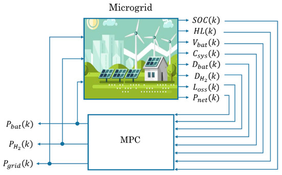
Figure 2.
General MPC controller architecture.
In practice, to carry out the MPC control strategy, it is necessary to define the constraints related to the physical limits of the microgrid. Therefore, to illustrate the procedure and without any loss of generality, the microgrid and MPC controller topology presented in Figure 1 and Figure 2, respectively, will be used. This one, modelled on (1), will be subjected to the constraints gathered in (2):
To match the constraints shown in (2) with those of the standard form , the problem is reduced to three inequalities: future control action constraints (ΔPbat, ΔPH2, ΔPgrid); plant input constraints (Pbat, PH2, Pgrid, Pnet); and plant output constraints (SOC, HL, Vbat, Csys, Dbat, DH2, LOSS).
The limit values SOCmin, SOCmax, HLmin, HLmax, Vbatmin and Vbatmax are associated with the minimum and maximum operating values defined by the safe operating margins of batteries and hydrogen-based storage systems. On the other hand, restrictions on operating powers are defined as the maximum power values (Pbat, PH2 and Pgrid) and variation in the power setpoint (ΔPbat, ΔPH2 and ΔPgrid) according to the sign criteria (the criterion defined regarding Figure 1, following the state-space discrete model (1) was that the delivered power had to be negative and the consumed power positive): In the case of batteries, the minimum and maximum value will be given by the maximum charging and discharging powers of the battery bank (, and , respectively), for the hydrogen system, the minimum and maximum value will be given by the nominal powers of the fuel cell and electrolyzer (Pmaxfc, ΔPmaxfc and Pmaxels, ΔPmaxels, respectively) and related to the use of the electricity grid, the minimum and maximum value will be given by the maximum values for the purchase/sale of energy to the grid (, and , , respectively).
2.2. MPC Cost Function. Guidelines for Parameter Tuning
The optimization problem to be solved at each time over the microgrid model can be included into the general expression of the cost function as (3).
where at sampling time k, αi are weighting factors corresponding to outputs deviations; and λi to the control efforts, and SOCr(k), HLr(k) and are the reference values or desired values associated with the battery state of charge, hydrogen level and bus voltage, respectively.
Once the objective function to be minimized has been defined in (3), and the constraints from (2) have also been considered, it is necessary to calculate the values for the weighting factors αi and λi, as well as the control and the prediction horizons Nu and Np, respectively, to obtain a desired system response on the short- and long-term basis [40,43].
The huge knowledge that authors have of the microgrid [42] allows the establishment of the following set of cause–effect relationships that help the parameters tuning process. Although it is a heuristic process, it is very intuitive and efficient, as will be seen in the different test that will be carried out. Table 2 summarizes the cause–effect relationships of each weighting factor on the performance of the microgrid MPC controller.
Table 2.
Cause–effect relationship between control parameters and microgrid response.
2.2.1. Short-Term Optimization
In the short-term operation, the aim is to guarantee the power balance, maximizing renewable utilization, while it is implemented a proper battery charging protocol, considering the role of each ESS and its response time horizon. Then, the parameters to be taken into account are control and prediction horizons Nu and Np, and from the objective function (3) are: the weighting factors related to the battery (α1, α3); hydrogen level (α2), general losses (α7), H2 system operation (α8), power balance (α10) and the control law effort (λ1, λ2, λ3). Additionally, the weighting factor α9 related to Pgrid should be included in case of grid-connected topologies.
In the first instance, the selection of the control and prediction horizons Nu and Np, respectively, are intimately linked to the system dynamics and the closed loop stability. In the case of a fast-dynamic system, it is unnecessary to use high control and prediction horizons because it must reach shortly its permanent regime, and the subsequent temporal evaluation is needless. In contrast, for a slow dynamic system, the use of a relatively high control and prediction horizons is necessary to evaluate the system performance throughout its transient response. In this case, it is advisable to use medium control and prediction horizons, due to the need to include the constraints of the control signal variation, which will impose a slower system dynamic. If these constraints are very strict, it can cause the multi-objective problem to become unfeasible. To find a reasonable solution, it is recommended to increase the control and prediction horizons so that the controller can evaluate the new transient response impose by the constraints.
On the other hand, the weighting factors of the reference tracking error (α1, α2, α3, α10) enable the controller to prioritize its objectives according to the current state of the microgrid. The main objective of short-term optimization is always to safeguard the power balance. For this reason, the weighting factor associated with the net power tracking error (α10) must have a high value (it represents a strong constraint), so any difference between Pnet and should be strongly penalized.
Weighting factors α1 and α2 are related to ESS, so they must guarantee the following: α1 is responsible for maintaining an optimum battery SOC; and α2 preserves an optimum HL. Therefore, both weighing factors need to have high values because the MPC controller must respond quickly if there is an increasing error in the tracking reference. However, the key is the ratio between both, which defines the optimal energy distribution between batteries and H2 storage system.
In this sense, in special applications, where it is required to maintain a certain level of hydrogen, α2 must be considered a high value. In these circumstances, electrolyzer and fuel cell will operate when the hydrogen level is lower or higher than the reference level respectively, independently of the power balance and energy requirements. On the other hand, in cases when hydrogen production is not crucial, but maintaining a desired reference hydrogen level is interesting, α2 will have a low value, and the use of H2 system will depend mainly on the battery SOC and the current energy situation.
Finally, the weighting factor α3 regulates the battery charge voltage control necessary to ensure a safe and efficient charging process. High values of this parameter will only make sense when the battery voltage reaches a high level and there is an excess of energy. For all other situations, this parameter must have a low value to avoid indiscriminate use of the remaining elements to impose the reference charge voltage. Hence, α3 must be adapted according to the energy situation. A way to tuning α3 can be solved using a fuzzy controller (see Section 3.2).
Considering the micro grid operation, the term in (3) related to operating power of H2 system, α8, must be low. In this sense, a reduced value of the parameter α8, will favour the use of the H2 storage system when the battery bank cannot cope with the energy imbalance. On the other hand, the weighting factor α7, linked to total Loss must be small, in this way, the losses in the microgrid must not determine its operation.
Considering the grid exchange energy flow, the weighting factor α9 will be determined by the interaction between the microgrid and the electrical grid. Then, it is possible to define as many cases as possibilities, depending on the system topology, regulatory framework, etc. Thus, isolated topologies or when it is necessary to prioritize the use of the renewable resources instead of the electrical grid, α9 must be represented by a high value. The purchase/sale of energy is penalized to the detriment of a more intensive use of the battery and H2 system. By contrast, if bidirectional energy exchange is allowed, the weighting factor α9 should be reduced. Certainly, hybrid solutions can be implemented, where the energy exchange is only penalized in one direction.
Finally, the weighting factor of the control vector, λ1, λ2 and λ3, allows the MPC controller to define the desired dynamics of the microgrid penalizing major variations of the operating point in systems that work better under low dynamic operation, i.e., electrolyser and fuel cell.
Then, a reduced value of the weighting factor related to the battery power, λ1, is recommended (λ1 > 0 to guarantee the convexity of the objective function). The battery must present fast response dynamics versus transients. In contrast, the H2 system requires a more conservative operation, so, λ2, will have a medium-high value. The weighting factor associated with the use of the external electrical grid, λ3, will depend on its role and the priority of the economic term in the cost function.
2.2.2. Long-Term Optimization
The weighting factors of the long-term optimization (α4, α5, α6) seek to maximize the microgrid’s performance while prolonging its useful lifespan. The optimization should respond to the objective of cost minimization () and the minimization of the battery and H2 system degradation ( and ).
Based on these objectives, the weighting factor α4 determines the weight of the economic objective in the ESS. Therefore, this parameter should have a high value when the microgrid is designed to provide maximum economic benefits.
On the other hand, the weighting factors that represent the battery and H2 system degradation (α5, α6), should not have fixed values but adapt according to the cumulative degradation in order to make a more conservative use of the most degraded equipment. For this purpose, a linear function is proposed (4), which allows calculating the updated weighting factor based on the accumulated degradation.
where:
αx(k + 1): Degradation weighting factor of the element x at sampling time k + 1, with x = 5 (battery) or 6 (H2 system).
Dx(i): Current degradation of the element x at sampling time i, with x = 5 (battery) or 6 (H2 system).
: Maximum expected degradation of the element x, with x = 5 (battery), 6 (H2 system).
Expression (4) can be tailored to the case of the battery (5), electrolyzer (6) and fuel cell (7), respectively.
Scalar coefficients, from a1 to b3, can be estimated through heuristic procedures based on experimental tests.
3. Results
In order to validate the behavior of the proposed MPC controller and tuning methodology, a case study is used that consists on the renewable source-based microgrid with hydrogen as backup, made available for this research by our Research Group at the University of Huelva (UHU). In this section, the microgrid is firstly described giving its technical characteristics. Next, the parameters tuning calculation used in the MPC controller as well as the constraints considered will be justified. Finally, simulations results corroborated with experimentation will show the performance of the microgrid both on the short- and long-term basis. The software tool used to implement the state–space model developed in Reference [30] and the MPC controller designed in Section 2 is Matlab®.
3.1. Description of the Renewable Source-Based Microgrid with Hydrogen as Backup
The renewable source-based microgrid with hydrogen as backup used in this paper is implemented at the University of Huelva and is shown in Figure 3.
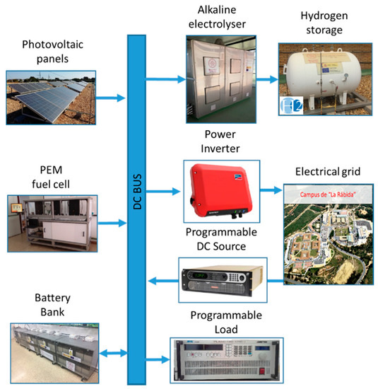
Figure 3.
Architecture of University of Huelva (UHU) renewable source-based microgrid with hydrogen as backup.
In the first instance, the renewable generation is represented by a monocrystalline photovoltaic (PV) array and the ESS is a lead-acid battery bank with direct connection to the DC bus. This connection involves the use of a proper charging control protocol to guarantee a safe voltage operating range. Additionally, the microgrid includes an H2 backup system, integrated by an alkaline electrolyzer, a Proton-Exchange Membrane (PEM) fuel cell and a medium pressure hydrogen tank for hydrogen storage. To enable bidirectional energy exchange between the electrical grid, there is a commercial inverter, and a programmable DC source. The programmable DC load can be used to simulate the load demand profile.
The technical characteristics of the different sub-systems are summarized in Table 3.
Table 3.
Main parameters of the UHU microgrid.
3.2. MPC Controller and Tuning Parameters
The MPC controller is based on the developed state–space model (1) and the developed theoretical MPC foundation in Section 2.
The weighting factors have been calculated following the design guidelines presented in Section 2.2. To implement the proposed tuning methodology, all system outputs have been scaled at a rate of 0–1 based on the maximum and minimum limits established by the microgrid constraints (2).
In this case, the main objective of the microgrid is always to guarantee the power balance, from a conservative and efficient use of the ESS, prioritizing the use of the microgrid’s resources, over the use of the electrical grid. For this, the battery operation is defined as a short-medium term ESS, while the H2 system will act as a long-term ESS.
Finally, the use of the external grid will be limited to ensure a more conservative use of electrolyzer and fuel cell, while at the same time it is possible to obtain an economic profit with the sale of the energy surplus.
Based on the above, a high value of the net power weighting factor (α10) was defined, to guarantee the power balance in each sampling period. Similarly, a fuzzy logic controller has been proposed for the calculation of the weighting factor of the battery voltage (α3), so that depending on the power balance, the working voltage and the energy surplus, it allows control of the battery charging voltage in accordance with the manufacturer’s specifications.
In order to define the operation of the ESS, a high value of the weighting factor of the battery SOC (α1), and a reduced value of the weighting factor of the hydrogen level (α2) have been used. With this, the use of H2 system is determined exclusively by the energy balance. Based on the above, the operation around the SOC reference defines the role of batteries as a short- and medium-term storage system, while the H2 system acts as a long-term storage system, operating under high and reduced SOC situations.
To define the priority in the use of the equipment, H2 system vs. external grid, a very low value of the weighting factor of H2 system (α8) has been opted against a high value of the weighting factor of the grid (α9), in such a way that the use of the external grid is strongly penalized against the H2 system, promoting the use of system resources.
Attending to the economic term, in this case, the economic optimization is not the main objective of the microgrid operation, and therefore a low-medium value of the operation cost weighting factor (α4) has been considered. On the other hand, the degradation parameters for battery (α5), electrolyser () and fuel cell () have been defined based on the linear function presented in (5)–(7). In this case, considering the high cost associated with electrolyzer and fuel cell, the slopes of their associated degradation functions (a2 and a3) are considerably higher than the battery degradation (a1). Then, H2 system degradation is more penalized and allows a longer lifespan. Similar function for electrolyzer and fuel cell has been chosen because they have similar operating characteristics.
Finally, to prioritize the use of the internal resources of the microgrid, the weighting factor associated with the operating losses (α7) has been kept very low.
Based on the weighting factors of the control signal variation (λ1, λ2 and λ3), very small values have been chosen. In this case, the use of the battery as a short-term storage system has been chosen, acting against any transient in the microgrid, and that is why the weighting factor λ1, acquires the lowest value. To maintain a safe and efficient operation of the electrolyser and fuel cell, a relatively high weighting factor of λ2 has been chosen, which ensures a slow dynamic operation. Finally, to guarantee the use of the battery in the first instance, as well as to preserve the slow dynamics of the H2 system, the weighting factor of the grid power variation, λ3, has a value ten times lower than the parameter λ2.
The main parameters of the MPC controller are summarized in Table 4.
Table 4.
Controller parameters and weighting factors.
In order to fit the weighting factor of the battery voltage α3, a Mandani fuzzy controller was implemented that enables the calculation of the optimal weighting factor to stablish the battery charging voltage protocol. In this sense, due to the large number of parameters associated with the objective function and therefore the controller, a heuristic process has been chosen for the design of the fuzzy controller, which is based on multiple simulations and experimental test of the system under different energy conditions.
The fuzzy rules have been designed in accordance with the battery charging control criteria. According to the above, the parameter α3 will have a low value when the battery voltage is considerably lower than the reference value or when the battery is under discharging process. On the other hand, during the charging process, the value of the parameter is calculated on the basis of the amount of energy intended for the battery charging, as well as the relationship between the current battery voltage and the reference value. In this respect, the fuzzy rules allow the calculation of the increase or decrease of the α3 parameter to ensure a safe operating margin as well as a smooth charging process.
The proposed fuzzy controller has the effect that in adverse conditions (high battery voltage and/or high charging power), the term associated to the battery voltage tracking problem is considered a strong constraint in the proposed multi-objective problem, guaranteeing the optimal charge control, thanks to the distribution of the energy surplus among the rest of the system equipment.
Table 5 and Figure 4 show, respectively, the inference matrix as well as the membership functions and the output surface of the proposed fuzzy controller.
Table 5.
Inference matrix of the fuzzy controller.
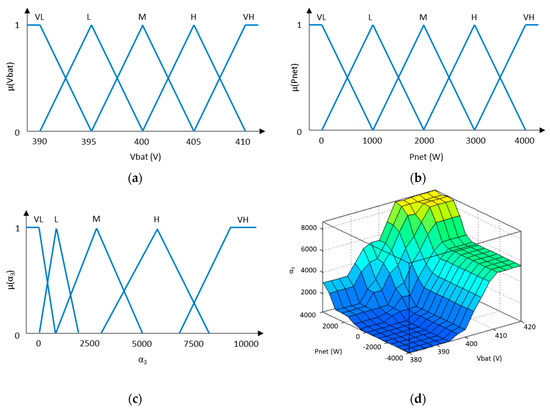
Figure 4.
(a) Battery bank voltage membership functions. (b) Microgrid net power membership functions. (c) Weighting factor α3 membership functions. (d) Fuzzy controller output surface.
Finally, considering the size of the microgrid, its maximum power capability (Table 3) and the manufacturer’s recommendations, the multi-objective function is subjected to the following constraints, (8):
3.3. Simulation and Experimental Tests
To validate the design methodology of the MPC controller and tuning guidelines, the proposed algorithm has been evaluated both on the short- and long-term basis. Under simulation on the short-term basis, the plant is checked for excess energy and deficit situations (Case I). In the long-term case, the response of the plant is analyzed when hydrogen-based subsystems suffer high degradation (Case II). Next, experimental testing is carried out considering energy excess and deficit cases (Cases III and IV). Due to the high cost of the equipment and the need for many tests across several months or even years, experimental tests are not carried out in the long-term tests.
3.3.1. Case I. Simulation Test. Short-term Optimization. Energy Excess and Deficit
In this case, the aim is to validate the performance of the microgrid under conditions of high excess energy and high deficit. This case represents the most unfavorable situation for the controller. The initial conditions of the plant are defined by a battery SOC of 65% and a hydrogen level of 4.5 Nm3. An equivalent degradation (0%) is considered in all systems. The renewable generation and load profile are shown in Figure 5a.
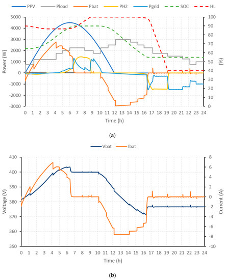
Figure 5.
Performance of the plant + MPC controller in Case I: high excess energy and high deficit. (a) Renewable power and load power, battery power, H2 system power, external grid power, battery SOC and hydrogen level; (b) battery voltage.
3.3.2. Case II. Simulation Test. Long-term Optimization. High Electrolyzer and Fuel Cell Degradation
The objective of the simulations presented in Case II is to validate the tuning methodology of the MPC controller parameters for long-term optimization. For this purpose, the controller and the microgrid are subjected to situations of high hydrogen-based subsystems degradation.
In this case, a high degradation in H2 system is considered (75% of maximum degradation), while the degradation associated to the battery is considered low (25% of maximum degradation). The initial conditions of the system are like those used in Case I.
3.3.3. Case III. Experimental Test. Short-term Optimization. Excess Energy Situation
In this case, the plant has been subjected to an energy excess condition under a stored energy level close to their higher limit. For this, two different tests have been carried out in which the microgrid is studied against a situation of excess energy for a variable operation (1); and another low dynamic operation with saturation in hydrogen production (2). The initial conditions of the microgrid are defined by a battery SOC of 70% and 80%, and a hydrogen level of 4.5 Nm3 and 4.8 Nm3. An equivalent degradation (10%) is considered in all systems.
3.3.4. Case IV. Experimental Test. Short-term Optimization. Energy Deficit Situation
Unlike the previous case, in this test the system has been subjected to an energy deficit condition under a stored energy level close to their lower limit. The objective of this case study is to validate the behavior of the MPC controller in the face of a limit discharge situation. The initial conditions of the system are defined by a battery SOC of 57.5% and a hydrogen level of 3.6 Nm3. An equivalent degradation (10%) is considered in all systems.
4. Discussion
Regardless of the case study, on energy excess situation, the battery deals firstly with excess energy, due to the reduced value of the weighting factor of the control signal variation (), until it reaches the desired charging voltage (400 VDC). (Please see Figure 5a,b (t < 10 h) and Figure 6a,b (t < 10 h).) Thereafter, the MPC controller regulates the charging power to keep the battery voltage around the reference with an error lower than 1%, regardless of the case under study (Cases I–IV) and the system operating conditions: low dynamic (Cases I, II, III) or variable operation (Case IV). From this moment, the charging battery protocol based on a fuzzy logic controller guarantees a safe and efficient charging process according to the battery charge acceptance curve, up to the maximum SOC constraint (SOC = 90%). (Please see Figure 5a and Figure 6a (7.5 h < t < 10 h).)
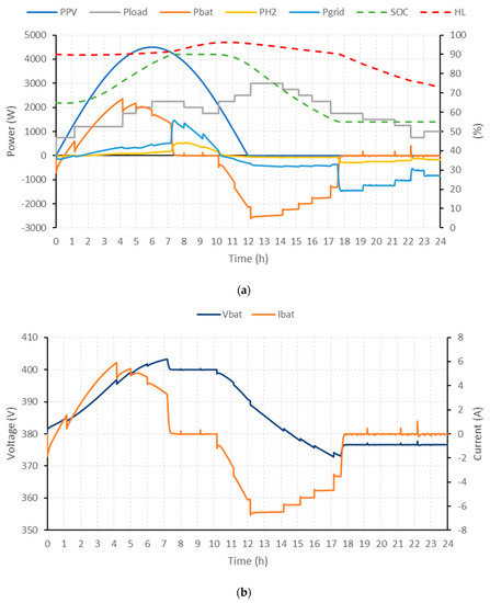
Figure 6.
Simulated performance of the microgrid + MPC controller in Case II: High degradation on H2 system. (a) Renewable power and load power, battery power, H2 system power, external grid power, battery SOC and hydrogen level; (b) battery voltage.
Based on the proposed tuning method, the MPC controller regulates the charging process through a perfect synchronism between battery, electrolyzer and external grid; according to the weighting factors of control signal variation (, and ), battery and H2 system accumulated degradation and operating priority (determined by and ). In this sense, the energy excess is used in the safest and most efficient way following design considerations, i.e., prioritizing the hydrogen production instead of selling energy to the external grid. This can be clearly seen in the battery, electrolyzer and external grid operating power profiles presented in Figure 5a (t < 10 h) and 6a (t < 10 h), as well as even faster in Figure 7a and Figure 8a.
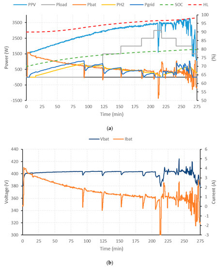
Figure 7.
Experimental performance of microgrid + MPC controller in Case III: excess energy for a variable operation (1). (a) Renewable power and load power, battery power, H2 system power, external grid power, battery SOC and hydrogen level; (b) battery voltage and current.
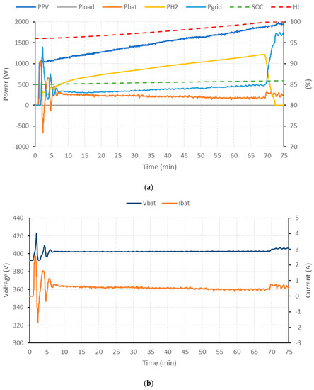
Figure 8.
Experimental performance of microgrid + MPC controller in Case III: saturation in hydrogen production (2). (a) Renewable power and load power, battery power, H2 system power, external grid power, battery SOC and hydrogen level; (b) battery voltage and current.
Attending exclusively to the control signal variation, it is verified that under dynamic operating conditions (Case III, energy excess situation (1)), the use of the electrolyzer is heavily penalized due to the specified constrains in the operating power variation. In accordance with the above, the external grid acts virtually as a battery charging regulation system, Figure 7 (t > 215 min).
In contrast, being an operation with a much lower dynamics (Case I and Case III excess energy situation), the operation of the electrolyzer is prioritised with respect to a small percentage of energy destined for sale to the external grid, Figure 5a (5 h < t < 10 h) and Figure 8a (t > 5 min).
Finally, in the case that the hydrogen level approaches the maximum capacity of the hydrogen tank (5 Nm3), a controlled switch-off of the electrolyzer is carried out. Then, the external grid is responsible for guaranteeing the power balance and the management of the battery charging protocol. (Please see Figure 5a (8 h < t < 16 h) and Figure 8a (t > 70 min).)
Given the energy deficit situation (Case I, Case II and Case IV), the reduced weighting factor of the battery power variation term () makes the battery absorb the transients in the net power set point instantaneously in order to cover the demand. Please see Figure 5a (t > 10 h), Figure 6a (t > 10 h) and 9a (around t = 50 min). Once the battery SOC is lower than that designated as optimal by the reference (SOC = 85%), the fuel cell and, with less intensity, the external grid, go into operation to reduce the excessive use of batteries. (Please see Figure 5a (t > 15 h), Figure 6a (t > 10 h) and Figure 9a,b (t > 0 min).) The energy distribution between battery and fuel cell is defined mainly from the term associated with the tracking error of the reference of the battery SOC, the dynamic imposed by the weighting factors associated with the control signal variation ( and ) and the current degradation, which directly influences the weighting factors of the degradation of batteries and the H2 system ( and ).
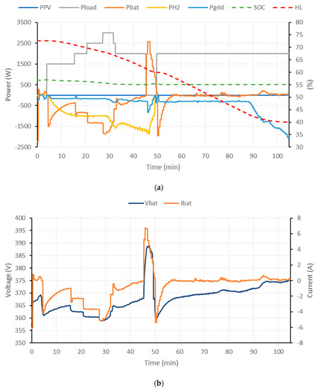
Figure 9.
Experimental performance of microgrid + MPC controller in Case IV: energy deficit situation. (a) Renewable power and load power, battery power, H2 system power, external grid power, battery SOC and hydrogen level; (b) battery voltage and current.
Reaching the minimum battery SOC (55%), it is the fuel cell and the external grid which guarantees the power balance. (Please see Figure 5a (t > 17 h), Figure 6a (t > 18 h), and Figure 9a,b (t > 47 min).) The energy distribution between fuel cell and grid cell is defined mainly from the weighting factors associated to the use of each system ( and ), the dynamic impose by the weighting factors associated with the control signal variation ( and ) and the current degradation which directly influences the weighting factor of the H2 system ().
Thus, in the case of reduced degradation of the fuel cell, its operation prevails over the use of the external grid, thanks to the use of a lower weighting factor ( < ) to maximize the use of the energy resources available. (Please see Figure 5a (t > 10 h) and Figure 9a (5 min < t < 90 min).) Although the priority is established by the design considerations, the external grid will act against changes in the net power set point, thanks to the lower restriction in the variation of the working power ( < ), in order to maintain a low dynamic and more conservative fuel cell operation.
Once the hydrogen level approaches the lowest limit, Figure 5a (t > 20 h), the controlled order to shut down the fuel cell, and it is ultimately the external grid which meets the demand. Unlike the previous case, the implementation of battery charge voltage controller is not required.
Finally, based on the influence of systems degradation, the increase in the use of the battery or hydrogen-based subsystems will be associated with an increase in its degradation and, therefore, a more conservative use will be required. The proposed adaptive tuning method for the weighting factor of the electrolyzer degradation (), battery degradation () and fuel cell degradation (), will allow the increase of the associated term on the cost function (4), which will result in less use of the most vulnerable equipment to the detriment of greater use of batteries/hydrogen system (depending on critical system) and external grid. Please see Case II in Figure 6a (10 h < t) for electrolyzer, battery and fuel cell degradation influence analysis respectively.
5. Conclusions
To ensure a safe and efficient operation of renewable energy microgrids, it is necessary to implement energy management strategies, which take into account all the characteristics of the microgrid and allow the supply to be guaranteed at all times, optimizing the response of the microgrid based on technical and economic criteria. This is especially important when the microgrid includes hydrogen systems (electrolyzers and fuel cells), due to its high cost and rapid degradation due to misuse.
Based on the needs raised, MPC-based techniques stand as a powerful tool for the design of multivariable controllers that optimize the response of the closed-loop system (microgrid + controller), taking into account the restrictions associated with the physical or operating limits of the systems connected to the microgrid. All this, together with the ability to predict any change in the output, makes the use of MPC controllers provide great advantages over traditional control techniques.
Although previous works can be found where the theory of predictive control is applied to hydrogen-based microgrids, most display particularized solutions have been adapted to the topology and application in question, thus greatly hindering their applicability to other cases. These works present concrete solutions, which focus on the short-term operation of the microgrid, ignoring pivotal technical-economic criteria for the optimization and operation of actual microgrids, both in the short and the long term.
In order to respond to the lack of general solutions based on predictive control applied to renewable source-based microgrid, this paper has presented a methodological foundation to design a MPC controller that can be applied to renewable source-based microgrid with hydrogen as backup. The methodology is sufficiently general to be used independent of the microgrid topology.
The resolution of the multi-objective optimization problem was carried out using a generalized quadratic cost function. The weighting factors have been calculated taking into account the role of each system connected to the microgrid, as well as technical and economic parameters based on the performance of the actual systems, including considerations related to the battery bank charging strategy, system efficiency, operating degradation or system costs in accordance with the selected topology and application both in the short and long-term.
The intrinsic difficulty in optimizing the multi-objective functions, as well as the large number of parameters to be optimized, make the tuning process a very complex task. Although a mathematical method to calculate the weighting factors is not presented, because it depends strongly on the microgrid topology and the final application, different cause–effect relationships have been explained and guidelines have been offered to facilitate the tuning process.
The MPC controller and the tuning methodology proposed have been checked in a case study, both under simulation and experimental tests.
Considering the test results, thanks to the predictive action of the MPC controller, the goodness of the model used, as well as the proposed tuning method, the ability of the controller to establish the proposed energy management strategy has been demonstrated, based on the design criteria and the operating limits defined by the equipment restrictions.
Results obtained in the case study show the validity of the model and tuning methodology of the MPC controller, offering a powerful tool to other researchers in the tasks of designing, controlling and managing microgrids with renewable generation and the use of hydrogen as energy vector.
Author Contributions
Conceptualization, F.J.V.F., F.S.M. and J.M.A.M.; methodology, F.J.V.F. and F.S.M.; software, F.J.V.F.; experimental data acquisition and model validation, F.J.V.F. and F.S.M.; writing, F.J.V.F., F.S.M. and A.J.C.G.; supervision, F.S.M., J.M.A.M. and A.J.C.G.; All authors have read and agreed to the published version of the manuscript.
Funding
This work is a contribution of the DPI2017-85540-R Project supported by the Spanish Ministry of Economy and Competitiveness and by the European Union Regional Development Fund.
Acknowledgments
The result of this work has been possible thanks to the contributions and conclusions obtained from the ERASMUS+ Programme, Project Hy2Green Ref. 2017-1-ES01-KA203-038302 and FEDER-UHU Programme, Project G2GH2 Ref. UHU-1259316.
Conflicts of Interest
The authors declare no conflict of interest.
List of Acronyms
| EMS | Energy Management System |
| ESS | Energy Storage System |
| H2 | Hydrogen |
| HL | Hydrogen level |
| LTI | Linear Time Invariant |
| LPV | Linear Parameter Variant |
| MILP | Mixed Integer Linear Programming |
| MIQP | Mixed Integer Quadratic Programming |
| MPC | Model Predictive Control |
| O&M | Operating and Maintenance |
| PV | Photovoltaic |
| SOC | State of Charge |
Notation and Symbols
| Weighting factor of tracking error. | |
| Degradation weighting factor of the element x at sampling time, with x = 5 (battery) or 6 (H2 sub-system). | |
| Weighting factor of control signal variation. | |
| System operating cost . | |
| Battery degradation (Ah/). | |
| Hydrogen sub-system degradation; (h/) for the electrolyser and (V/) for the fuel cell. | |
| Current degradation of the element x at sampling time, with x = 5 (battery) or 6 (H2 sub-system). | |
| Maximum expected degradation of the element x, with x = 5 (battery), 6 (H2 system). | |
| Hydrogen level (Nm3). | |
| Reference of the hydrogen level (Nm3). | |
| Microgrid losses (W). | |
| Battery power (W). | |
| Hydrogen system power consumed (if electrolyser is on,)/supplied (if fuel cell is on,) (W). | |
| Power consumed ()/supplied () from/to the electrical grid (W). | |
| Net power in the microgrid (W). | |
| Reference net power in the microgrid (W). | |
| Photovoltaic power generation (W). | |
| Battery state of charge (%). | |
| Reference of the battery state of charge (%). | |
| Sampling time (s). | |
| Battery voltage (V). | |
| Reference battery voltage (V). |
References
- Chauhan, A.; Saini, R.P. A review on Integrated Renewable Energy System based power generation for stand-alone applications: Configurations, storage options, sizing methodologies and control. Renew. Sustain. Energy Rev. 2014, 38, 99–120. [Google Scholar] [CrossRef]
- Vivas, F.J.; De Las Heras, A.; Segura, F.; Andújar, J.M. A review of energy management strategies for renewable hybrid energy system with hydrogen backup. Renew. Sustain. Energy Rev. 2018, 82, 126–155. [Google Scholar] [CrossRef]
- Vivas, F.J.; De las Heras, A.; Segura, F.; Andújar, J.M. H2RES2 simulator. A new solution for hydrogen hybridization with renewable energy sources-based systems. Int. J. Hydrogen Energy 2017, 42, 13510–13531. [Google Scholar] [CrossRef]
- Vivas, F.J.; de las Heras, A.; Segura, F.; Andújar, J.M. Cell voltage monitoring All-in-One. A new low cost solution to perform degradation analysis on air-cooled polymer electrolyte fuel cells. Int. J. Hydrogen Energy 2019. [Google Scholar] [CrossRef]
- Tesfahunegn, S.G.; Ulleberg, Ø.; Vie, P.J.S.; Undeland, T.M. Optimal shifting of Photovoltaic and load fluctuations from fuel cell and electrolyzer to lead acid battery in a Photovoltaic/hydrogen standalone power system for improved performance and life time. J. Power Sources 2011, 196, 10401–10414. [Google Scholar] [CrossRef]
- Ipsakis, D.; Voutetakis, S.; Seferlis, P.; Stergiopoulos, F.; Papadopoulou, S.; Elmasides, C. The effect of the hysteresis band on power management strategies in a stand-alone power system. Energy 2008, 33, 1537–1550. [Google Scholar] [CrossRef]
- Torreglosa, J.P.; García, P.; Fernández, L.M.; Jurado, F. Hierarchical energy management system for stand-alone hybrid system based on generation costs and cascade control. Energy Convers. Manag. 2014, 77, 514–526. [Google Scholar] [CrossRef]
- Athari, M.H.; Ardehali, M.M. Operational performance of energy storage as function of electricity prices for on-grid hybrid renewable energy system by optimized fuzzy logic controller Operational performance of energy storage as function of electricity prices for on-grid hybrid renew. Renew. Energy 2016, 85, 890–902. [Google Scholar] [CrossRef]
- Naderi, E.; Pourakbari-Kasmaei, M.; Cerna, F.V.; Lehtonen, M. A novel hybrid self-adaptive heuristic algorithm to handle single- and multi-objective optimal power flow problems. Int. J. Electr. Power Energy Syst. 2020, 125, 106492. [Google Scholar] [CrossRef]
- Naderi, E.; Pourakbari-Kasmaei, M.; Abdi, H. An efficient particle swarm optimization algorithm to solve optimal power flow problem integrated with FACTS devices. Appl. Soft Comput. J. 2019, 80, 243–262. [Google Scholar] [CrossRef]
- Naderi, E.; Narimani, H.; Fathi, M.; Narimani, M.R. A novel fuzzy adaptive configuration of particle swarm optimization to solve large-scale optimal reactive power dispatch. Appl. Soft Comput. J. 2017, 53, 441–456. [Google Scholar] [CrossRef]
- Bordons, C.; García-Torres, F.; Valverde, L. Gestión Óptima de la Energía en Microrredes con Generación Renovable. Rev. Iberoam. Autom. Inform. Ind. 2015, 12, 117–132. [Google Scholar] [CrossRef]
- Talebian, M.E.; Plant, P.; Sobhani, S.; Borzooi, A. New Hybrid System of Fuel Cell Power Plant and Wind Turbine for Household Consumption. In Proceedings of the 3rd International Conference on Electric Power and Energy Conversion Systems, Yildiz Technical University, Istanbul, Turkey, 2–4 October 2013. [Google Scholar]
- Wang, X.; Tong, C.; Palazoglu, A.; El-Farra, N.H. Energy Management for the Chlor-Alkali Process with Hybrid Renewable Energy Generation using Receding Horizon Optimization. In Proceedings of the 53rd IEEE Conference on Decision and Control, Los Angeles, CA, USA, 15–17 December 2014; pp. 4838–4843. [Google Scholar]
- Velarde, P.; Maestre, J.M.; Ocampo-Martinez, C.; Bordons, C. Application of robust model predictive control to a renewable hydrogen-based microgrid. In Proceedings of the 2016 European Control Conference (ECC), Aalborg, Denmark, 29 June–1 July 2016; pp. 1209–1214. [Google Scholar] [CrossRef]
- Valverde, L.; Bordons, C.; Rosa, F. Power Management Using Model Predictive Control in a Hydrogen-based Microgrid. In Proceedings of the IECON 2012-38th Annual Conference on IEEE Industrial Electronics Society, Montreal, QC, Canada, 25–28 October 2012; pp. 5669–5676. [Google Scholar] [CrossRef]
- Valverde, L.; Rosa, F.; Bordons, C.; Guerra, J. Energy Management Strategies in hydrogen Smart-Grids: A laboratory experience. Int. J. Hydrog. Energy 2016, 41, 13715–13725. [Google Scholar] [CrossRef]
- Nassourou, M.; Puig, V.; Blesa, J.; Ocampo-Martinez, C. Economic Model Predictive Control for Energy Dispatch of a Smart Micro-Grid System. In Proceedings of the 2017 4th International Conference on Control, Decision and Information Technologies (CoDIT), Barcelona, Spain, 5–7 April 2017; pp. 944–949. [Google Scholar] [CrossRef]
- Bruni, G.; Cordiner, S.; Mulone, V.; Rocco, V.; Spagnolo, F. A study on the energy management in domestic micro-grids based on model predictive control strategies q. Energy Convers. Manag. 2015, 102, 50–58. [Google Scholar] [CrossRef]
- Torreglosa, J.P.; García, P.; Fernández, L.M.; Jurado, F. Energy dispatching based on predictive controller of an off-grid wind turbine/photovoltaic/hydrogen/battery hybrid system. Renew. Energy 2015, 74, 326–336. [Google Scholar] [CrossRef]
- Benne, M.; Grondin, D.; Damour, C.; Hilairet, M.; Kbidi, F. Energy Management System in Micro-Grid with Storage and Hydrogen Production. In Proceedings of the IECON 2018-44th Annual Conference of the IEEE Industrial Electronics Society, Washington, DC, USA, 21–23 October 2018. [Google Scholar] [CrossRef]
- Fu, C.; Lin, J.; Song, Y.; Zhou, Y.; Mu, S.; Lv, K.G.; Pdwxuh, D.U.; Qdphg, W.; Wr, W.K.H.; Ri, V.; et al. Model Predictive Control of an Integrated Energy Microgrid Combining Power to Heat and Hydrogen. In Proceedings of the IEEE Conference on Energy Internet and Energy System Integration (EI2), Beijing, China, 26–28 November 2017; pp. 1–6. [Google Scholar]
- Sevilla, F.R.S.; Park, C.; Knazkins, V.; Korba, P. Model Predictive Control of Energy Systems with Hybrid Storage. In Proceedings of the 2016 IEEE Power and Energy Society General Meeting, Boston, MA, USA, 17–21 July 2016; pp. 1–5. [Google Scholar] [CrossRef]
- Trifkovic, M.; Sheikhzadeh, M.; Nigim, K.; Daoutidis, P. Modeling and control of a renewable hybrid energy system with hydrogen storage. IEEE Trans. Control Syst. Technol. 2014, 22, 169–179. [Google Scholar] [CrossRef]
- Pereira, M.; Limon, D.; Alamo, T.; Valverde, L.; Bordons, C. Economic Model Predictive Control of a Smartgrid with Hydrogen Storage and PEM Fuel Cell. In Proceedings of the IECON 2013–39th Annual Conference of the IEEE Industrial Electronics Society, Vienna, Austria, 10–13 November 2013; pp. 7920–7925. [Google Scholar] [CrossRef]
- Pereira, M.; Munoz De La Pena, D.; Limon, D. Robust economic model predictive control of a community micro-grid. Renew. Energy 2016, 100, 2739–2744. [Google Scholar] [CrossRef]
- Acevedo-Arenas, C.Y.; Correcher, A.; Sánchez-Díaz, C.; Ariza, E.; Alfonso-Solar, D.; Vargas-Salgado, C.; Petit-Suárez, J.F. MPC for optimal dispatch of an AC-linked hybrid PV/wind/biomass/H2 system incorporating demand response. Energy Convers. Manag. 2019, 186, 241–257. [Google Scholar] [CrossRef]
- Petrollese, M.; Valverde, L.; Cocco, D.; Cau, G.; Guerra, J. Real-time integration of optimal generation scheduling with MPC for the energy management of a renewable hydrogen-based microgrid. Appl. Energy 2016, 166, 96–106. [Google Scholar] [CrossRef]
- Clarke, W.C.; Manzie, C.; Brear, M.J. An Economic MPC Approach to Microgrid Control. In Proceedings of the 2016 Australian Control Conference (AuCC), Newcastle, NSW, Australia, 3–4 November 2016; pp. 276–281. [Google Scholar] [CrossRef]
- Parisio, A.; Rikos, E.; Glielmo, L. Stochastic model predictive control for economic/environmental operation management of microgrids: An experimental case study. J. Process Control 2016, 43, 24–37. [Google Scholar] [CrossRef]
- Zhang, Y.; Meng, F.; Wang, R.; Zhu, W.; Zeng, X.J. A stochastic MPC based approach to integrated energy management in microgrids. Sustain. Cities Soc. 2018, 41, 349–362. [Google Scholar] [CrossRef]
- Parisio, A.; Rikos, E.; Tzamalis, G.; Glielmo, L. Use of model predictive control for experimental microgrid optimization. Appl. Energy 2014, 115, 37–46. [Google Scholar] [CrossRef]
- Pereira, M.; Limon, D.; De La Peña, D.M.; Valverde, L.; Alamo, T. Periodic Economic Control of a Nonisolated Microgrid. IEEE Trans. Ind. Electron. 2015, 62, 5247–5255. [Google Scholar] [CrossRef]
- Garcia, F.; Bordons, C. Regulation Service for the Short-Term Management of Renewable Energy Microgrids with Hybrid Storage Using Model Predictive Control. In Proceedings of the IECON 2013-39th Annual Conference of the IEEE Industrial Electronics Society, Vienna, Austria, 10–13 November 2013; pp. 7962–7967. [Google Scholar] [CrossRef]
- Garcia-torres, F.; Bordons, C. Optimal Economical Schedule of Hydrogen-Based Microgrids With Hybrid Storage Using Model Predictive Control. IEEE Trans. Ind. Electron. 2015, 62, 5195–5207. [Google Scholar] [CrossRef]
- Pereira, M.; Limon, D.; Alamo, T.; Valverde, L. Application of Periodic Economic MPC to a Grid-Connected Micro-Grid. IFAC-PapersOnLine 2015, 48, 513–518. [Google Scholar] [CrossRef]
- Salazar, J.; Valverde, L.; Tadeo, F. Predictive Control of a Renewable Energy Microgrid with Operational Cost Optimization. In Proceedings of the IECON 2013-39th Annual Conference of the IEEE Industrial Electronics Societ, Vienna, Austria, 10–13 November 2013; pp. 7950–7955. [Google Scholar] [CrossRef]
- Liu, L.; Ling, D.; Wu, Y.; Zheng, Y. Process Model Quality Monitoring of Model Predictive Controller. In Proceedings of the 2017 36th Chinese Control Conference (CCC), Dalian, China, 26–28 July 2017; pp. 4391–4396. [Google Scholar] [CrossRef]
- Tang, X.; Liu, B.; Lv, Z.; Gao, F. Observer based battery SOC estimation: Using multi-gain-switching approach. Appl. Energy 2016. [Google Scholar] [CrossRef]
- Wojsznis, W.; Gudaz, J.; Blevins, T.; Mehta, A. Practical approach to tuning MPC. ISA Trans. 2007, 42, 149–162. [Google Scholar] [CrossRef]
- Garcia-Torres, F.; Valverde, L.; Bordons, C. Optimal Load Sharing of Hydrogen-Based Microgrids with Hybrid. IEEE Trans. Ind. Electron. 2016, 63, 4919–4928. [Google Scholar] [CrossRef]
- Vivas, F.J.; Segura, F.; Andújar, J.M.; Caparrós, J.J. A suitable state-space model for renewable source-based microgrids with hydrogen as backup for the design of energy management systems. Energy Convers. Manag. 2020, 219, 113053. [Google Scholar] [CrossRef]
- Garriga, J.L.; Garriga, J.L.; Soroush, M. Model Predictive Control Tuning Methods: A Review Model Predictive Control Tuning Methods: A Review. Ind. Eng. Chem. Res. 2013, 49, 3505–3515. [Google Scholar] [CrossRef]


Publisher’s Note: MDPI stays neutral with regard to jurisdictional claims in published maps and institutional affiliations. |
© 2020 by the authors. Licensee MDPI, Basel, Switzerland. This article is an open access article distributed under the terms and conditions of the Creative Commons Attribution (CC BY) license (http://creativecommons.org/licenses/by/4.0/).