Article

A Rule-Based Fuzzy Logic Methodology for Multi-Criteria Selection of Wind Turbines

1
Center for Engineering Research, Research Institute, King Fahd University of Petroleum & Minerals, Dhahran 34464, Saudi Arabia
2
College of Computing and Information Sciences, Karachi Institute of Economics and Technology, Karachi 75190, Pakistan
*
Author to whom correspondence should be addressed.
Sustainability 2020, 12(20), 8467; https://doi.org/10.3390/su12208467
Submission received: 10 September 2020 / Revised: 30 September 2020 / Accepted: 2 October 2020 / Published: 14 October 2020

Abstract

:
The domain of renewable energy has seen tremendous growth in the past many years. This growth has shown optimism for a sustainable future and promises to lead the human race towards a cleaner and healthier environment. Wind energy, which is a vital part of this clean energy revolution, has received significant attention globally. To get benefit from wind energy, wind farms need to be developed with the highest efficiency so that the maximum energy can be harnessed. A key decision in this development process is selection of a turbine type that shows highest compatibility with the geographical and topographical features of the site where the turbines are to be installed. In practical terms, the turbine selection mechanism should consider several decision criteria. In many cases, these criteria are conflicting with each other. Furthermore, the choice and aspirations of the decision-maker who selects these turbines should be considered in the selection process and should be flexible. This paper presents a preliminary study on a rule-based turbine selection methodology which is based on the concepts of fuzzy logic. The proposed methodology analyzes several scenarios in conjunction with the turbine selection model. The applicability of the methodology is demonstrated via two test scenarios. Data from a real potential site in Saudi Arabia were used, and 17 turbines from different manufacturers and with rated capacities in range of 1.5–3 MW were evaluated. The results indicate that the proposed scheme is able to incorporate decision-maker’s aspirations and effectively reflects these aspirations in the turbine selection process.

Graphical Abstract

1. Introduction

During the last couple of decades, the world has suffered from various environmental issues. Air pollution, water pollution, noise pollution, soil and radioactive contamination, and plastic pollution are major elements of the environmental pollution. The main cause of this environmental pollution can be attributed to the demands pertaining to improved quality of living standards worldwide, which has resulted in increased demand for energy as well. However, the traditional sources of energy supply, which mainly consist of fossil fuels, have contributed significantly to various forms of pollution. Due to the alarming rate of increase in pollution levels around the globe, research is focusing on finding solutions to various problems with one main goal: a sustainable future. Accordingly, a notable level of attention has been given to reduce (and eventually eliminate) reliance on fossil fuels and to find alternative sources of cheap and clean energy for sustainable times ahead.
With the aim of harnessing clean energy, various solutions have been proposed over the years. One area which has received significant attention by researchers is wind energy. The interest in wind energy is due to several reasons. Wind energy is cheap; the cost of generation, operations, and maintenance is substantially less than energy generation from fossil fuels [1]. The time required for deployment and commissioning of a wind farm is also far less than that required for establishing an energy generation plant that runs on oil, gas, or coal. Furthermore, unlike the resources of fossil fuels, which are owned and controlled by certain countries and governments, wind is not affected by geographical boundaries or geopolitical conflicts.
At a commercial level, wind energy is obtained by developing wind farms in windy regions. One crucial phase in the development of a commercially viable wind farm is the selection of a turbine type that meets the geographical, topographical, and climatic characteristics of the wind farm site under consideration. This selection is often governed by several decision criteria, where one or more decision criteria are conflicting with each other. To address this multi-criteria nature of the turbine selection problem, several approaches exist. These approaches are broadly covered under the domain of multi-criteria decision-making (MCDM).
The MCDM approaches are used to solve decision problems where multiple criteria are involved in the decision making process. These criteria are in conflict with each other, in addition to being mutually incommensurable. Conflict refers to a situation where improvement in the quality of decision in one criterion results in a negative impact on at least one other decision criterion. For example, in a factory X, if the work force is to be minimized while total earnings are to be maximized, then the two objectives are conflicting since reduction in work force will minimize the total earnings as well (which is not desired). Incommensurability refers to a situation where the decision criteria have different units and magnitudes. In the example above, the work force and total earnings are incommensurable since work force is a head count while total earnings is the amount of money in a certain currency. In addition, the work force could be in the hundreds, while the total earnings could be in the millions.
Over the years, several MCDM techniques have been developed by researchers. Some well-known techniques include weighted sum method [2], goal programming [3], TOPSIS [4], VIKOR [5], ELECTRE [6], AHP [7], PROMETHEE [8], Grey relational analysis [9], minimum Manhattan distance (MMD) approach [10], and fuzzy logic [11], among many others [12]. In the context of MCDM problems, two possible decision scenarios may be encountered by the decision-maker. These scenarios can be illustrated by the following two decision rules as examples:
Example 1.
IF Criterion A is optimized AND Criterion B is optimized AND Criterion C is optimized THEN the Result D is also optimized.
Example 2.
IF Criterion A is optimized OR Criterion B is optimized OR Criterion C is optimized THEN the Result D is also optimized.
In Example 1, there are three decision criteria, namely Criteria A, B, and C, and optimization of all three is mandatory in order to reach an optimized decision represented by Result D. If any one of the three decision criteria is not optimized, even though we optimize the other two input criteria, then Result D will not be optimized. In contrast, the decision rule in Example 2 requires optimization of any one of the three input criteria in order optimize Result D.
A limitation of the MCDM techniques, including the ones mentioned above (with the exception of fuzzy logic) is that they are designed to deal with problems depicting situations shown in Example 1. That is, the techniques can effectively solve MCDM problems where the decision is to be taken based on the ’AND’ operation between the criteria. These techniques are not equipped to deal with the situation illustrated in Example 2 where the decision rule is based on the ’OR’ operation. Fuzzy logic, on the other hand, has an exceptional capability in the sense that it can deal with decisions rules where AND or OR operations are present. More specifically, fuzzy logic can deal with AND operation through the t-norm functions while the OR situation can be handled through the s-norm functions [11]. This feature of fuzzy logic allows easy handling of situations where the decision may involve the mixed AND-OR type rules, which is the focus of the present study and provides the main motivation to employ fuzzy logic for developing and implementing several decision rules for turbine selection. While other MCDM techniques may be computationally or methodologically better than fuzzy logic, they lack the s-norm type capability and therefore cannot be applied to situations other than the ones involving the AND operation between the input criteria.
Another motivation to advocate the use of fuzzy logic for the multi-criteria turbine selection problem is the uncertainties and impreciseness associated with the problem data. The multi-criteria turbine selection problem typically deals with decision variables that involve imprecise data. The literature has identified a number of such decision variables which include hub height, wind speed, turbine reliability, maintenance organization, percentages of zero output and rated output, annual energy production, net capacity factor, tip speed ratio, system reliability indices, and many others [13]. Fuzzy logic is naturally designed to efficiently deal with imprecise data which makes the logic an effective tool to deal with the turbine selection problem.
One more aspect that makes fuzzy logic an attractive choice for the multi-criteria turbine selection problem is computational efficiency of the technique. Many studies [14,15,16,17,18,19] have used algorithms, such as genetic algorithms, differential evolution, and particle swarm optimization, which are promising in producing efficient solution, but at the expense of computational efficiency. In contrast, fuzzy logic is not only effective in producing quality solutions, but is also computationally efficient.
With the consideration of the above issues, this paper presents a fuzzy logic based flexible framework to deal with the turbine selection problem which is modeled as an MCDM problem. Accordingly, the main contributions of the paper can be enumerated as follows:
  • A fuzzy logic based approach is proposed that allows the decision maker to develop flexible decision rules for the turbine selection problem. The proposed approach is robust and scalable, and can be extended to accommodate any number of decision criteria in the selection process.
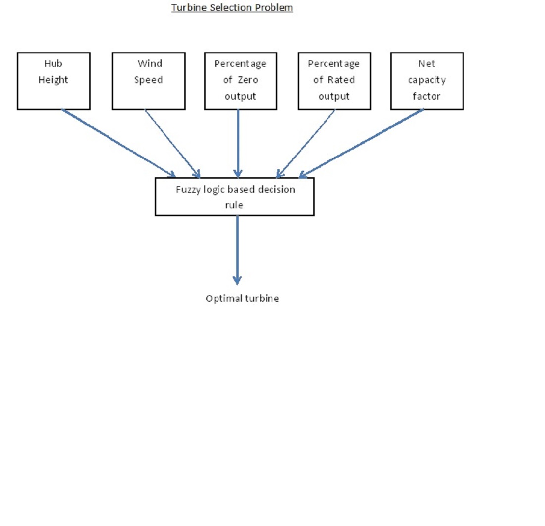
  • The turbine selection problem is modeled as an MCDM problem considering five decision criteria. These criteria include hub height, wind speed, percentage of zero power, percentage of rated power, and net capacity factor. The importance of these criteria is endorsed by several previous studies [19,20,21,22,23].
  • The Unified AND-OR (UAO) fuzzy operator [24] is employed for conversion of fuzzy rules to numerical values. The UAO operator is specifically selected due to its flexibility in handling the ANDing and ORing scenarios, as explained below. Furthermore, while the UAO operator has previously been applied to turbine selection problem on a simple model, the application of the operator to the new decision model mentioned above will be the first such attempt.
  • As opposed to many previous studies on turbine selection, where hypothetical data were used, the present study utilized real data collected from a potential site in Saudi Arabia. However, the proposed approach can be applied to any type of data, whether synthetic or real.
The rest of this paper is organized as follows. Section 2 highlights previous research and current status of the turbine selection problem. This is followed by a discussion on fuzzy logic in the context of the problem model in Section 3. Fuzzy logic-based decision methodology and rules are presented in Section 4. The results are discussed in Section 5 through application examples of two decision rules using real data. Finally, concluding remarks are provided in Section 6.

2. Literature Review

Numerous studies have addressed the turbine selection problem as a multi-criteria decision-making problem with various solution techniques. Sarja and Halonen [25] identified product reliability and availability, production volume, cost, and maintenance management as important factors for turbines selection. However, the study did not suggest any decision model. Perkin et al. [14] used rotor diameter, generator size, hub height, pitch angle range, and rotations per minute (RPM) range as the decision criteria which were used in conjunction with the genetic algorithm. However, the choice of genetic algorithm was a point of concern due to the algorithm’s computational complexity. Montoya et al. [16] also utilized genetic algorithm with power output and deviation in daily power output as the decision criteria. El-Shimy [26] considered capacity factor, normalized average power output, and turbine-performance-index and used site-specific data. Dong et al. [18] utilized a number of algorithms from the domain of natural computing. These algorithms included genetic algorithms, particle swarm optimization, and differential evolution for turbine selection. They used matching index, turbine cost index, and the integrated matching index as the selection criteria. Shirgholami et al. [27] identified over 30 decision criteria for turbine selection, but suggested that only a subset of the criteria can be used depending on the requirements of the turbine selection problem model and site under consideration. An Analytic Hierarchy Process (AHP) based approach was used as the underlying turbine selection technique. Yorukoglu [28] proposed a turbine selection strategy based on MULTIMOORA method while considering six criteria. These criteria were reliability, production, service life, first cost, noise, and operation cost. Lee et al. [29] proposed a multi-criteria decision approach considering four decision criteria, namely, machine characteristics, economic aspects, environmental issues, and technical challenges. However, one major limitation of their study was that they only focused on the problem foundations without showing actual implementation on real data. Khan and Rehman [22,30] first proposed the use of fuzzy logic for turbine selection while considering hub height, zero output percentage, and rated output percentage as the decision criteria. They also proposed an enhanced two-tier selection approach [13] based on fuzzy logic. Furthermore, they also proposed goal programming and weighted sum approaches for turbine selection [21,31,32]. However, the decision models were simpler compared to what is proposed in this paper.
Şağbanşua and Balo [33] utilized the AHP approach for turbine selection using models from different manufacturers. Although they considered technical, economic, environmental, and customer related factors, the testing of their model was validated on turbines with rated capacity 1.5 MW only. Shateranlou and PourHossein [34] proposed a blade element momentum (BEM) method combined with multi-objective optimization algorithms to select the best turbine while using turbine blade radius, tip speed ratio, blade sectional radius width (chord), twisting angle distribution, turbine tower height, and blade airfoil standard as the decision criteria. Dinmohammadi and Shafiee [35] developed a hybrid approach combining AHP and TOPSIS while considering bottom fixed, floating, vertical-axis, horizontal-axis, gearbox-operated, and gearless wind turbines. Sedaghat et al. [19] proposed a turbine selection model while using the levelized cost of electricity, capacity factor, and normalized annual energy production as the decision criteria. The underlying technique was based on the concept of Pareto ranking to select the best turbine. Beskese et al. [36] proposed a hybrid method that integrated AHP with TOPSIS approach for wind turbine evaluation for a potential site in Turkey. Their model was based on qualitative and quantitative data analysis.

3. Fuzzy Logic Based Turbine Selection Model

The fuzzy logic based MCDM approach requires criteria to be aggregated in the form of a decision function, which is termed as overall membership function in this paper. This decision function is the mathematical mapping of a decision rule. An important consideration in the formation of the decision function is the mathematical structure of the function. Typically, turbine selection problems have been modeled in a way that requires satisfaction/optimization of all criteria simultaneously which results in the so called “ANDing” (intersection) operation between decision criteria, as shown in Example 1. To deal with this, a number of fuzzy mathematical operators (i.e., functions) have been proposed in literature. These include Werners’ operator, Dubois and Prade operator, Yager’s ordered weighted average (OWA) operator, Hamacher’s operator, Einstein operator, and Unified AND-OR (UAO), among many others [37]. In contrast to “ANDing”, there might be decision requirements that require “ORing” between one or more criteria, as illustrated through Example 2 above. To address this scenario, the aforementioned operators have a counterpart that implements the OR function. However, the mathematical representation of AND and OR functions require two different equations, with the exception of the UAO operator. The UAO operator [24] is different and unique in the sense that a single equation is used for both AND and OR functions. Due to this capability of the UAO operator, its use has been reported in many previous studies [38,39,40,41,42,43,44,45,46,47], including simpler versions of the turbine selection problem [22,48]. Therefore, the operator is used in this paper with an improved problem model. To maintain comprehensiveness, the operator is briefly discussed below.

3.1. The Unified AND-OR Operator

The main characteristic of the UAO operator is that it can either behave as the “AND” function or the “OR” function, but uses a single equation. The behavior of the operator as AND or OR is controlled through a variable ν 0 whose value decides the behavior of the operator. Mathematically, the operator is represented as follows [24]:
f ( μ A , μ B ) = μ A μ B + ν max { μ A , μ B } ν + max { μ A , μ B } = { I = μ A B ( x ) if ν > 1 I * = μ A B ( x ) if ν < 1
where μ A represents the membership value of first decision criterion, μ B represents the membership value of the second decision criterion, and f ( μ A , μ B ) represents the overall membership value of the decision. I * denotes the AND operation using the UAO operator and I represents the OR operation using the UAO operator. With 0 < ν < 1 , the UAO behaves as the AND operator, whereas ν > 0 gives the OR behavior. Further details and mathematical properties of the UAO operator can be found in the study by Khan and Engelbrecht [24].
In accordance with the theory of fuzzy logic [11], the overall membership value that signifies the quality decision should be obtained. This requires formation of the overall membership function as well as the membership functions of the individual selection criteria. In the context of multi-criteria turbine selection problem, the decision model is based on five selection criteria as discussed earlier. The formation of membership functions for these criteria is motivated by previous studies [22,48] and is presented below.

3.2. Membership Functions for the Selection Criteria

To employ the UAO operator for turbine selection, five linguistic variables need to be defined: “hub height”, “wind speed”, “percentage of zero output”, “percentage of rated output”, and “net capacity factor”. Our interest is in the terms “low hub height”, “high wind speed”, “low zero output percentage”, “high rated output percentage”, and “high net capacity factor”. Since conflict exists between criteria, the objective is to find the optimal ratio that provides the best tradeoff between the criteria. This optimal ratio is the decision function that is represented by membership function “optimal turbine”.
As mentioned above, each decision criteria is defined by a membership function μ . The membership function lies in range [0,1] which describes the degree of satisfaction with the decision criterion under consideration. The higher is the value (towards 1) for the output of “optimal turbine”, the better is the turbine in terms of its quality (optimality).
The membership functions for the five criteria are found as follows. First, the membership function for hub height is formed by first defining the upper and lower limits, denoted by h m a x and h m i n , respectively. Note that the hub height is desired to be decreased. Accordingly, the membership function is given as
μ h ( x ) = 1 if H e i g h t ( x ) h m i n h m a x H e i g h t ( x ) h m a x h m i n if h m i n < H e i g h t ( x ) h m a x 0 if H e i g h t ( x ) > h m a x
where the term H e i g h t ( x ) represents the hub height of a combination x.
Similarly, the membership function for wind speed is defined as follows. The upper and lower limits of wind speed are denoted by w m a x and w m i n , where the intention is to increase the wind speed.
μ w ( x ) = 1 if W i n d ( x ) w m a x W i n d ( x ) w m i n w m a x w m i n if w m i n W i n d ( x ) < w m a x 0 if W i n d ( x ) < w m i n
where the term W i n d ( x ) represents the wind speed of a combination x.
The membership function for percentage of zero output can be defined as follows, where z m a x and z m i n represent the upper and lower limits, respectively. The requirement is to decrease the percentage of zero output.
μ z ( x ) = 1 if Z e r o ( x ) z m i n z m a x Z e r o ( x ) z m a x z m i n if z m i n < Z e r o ( x ) z m a x 0 if Z e r o ( x ) > z m a x
where the term Z e r o ( x ) represents the percentage of zero output of a combination x.
With regard to the percentage of rated output, the corresponding membership function can be defined as given below. Here, r m a x and r m i n represent the upper and lower limits, respectively. The percentage of rated output is intended to be decreased.
μ r ( x ) = 1 if R a t e d ( x ) r m a x R a t e d ( x ) r m i n r m a x r m i n if r m i n R a t e d ( x ) < r m a x 0 if R a t e d ( x ) < r m i n
where the term R a t e d ( x ) represents the percentage of rated output of a combination x.
Finally, the membership function for net capacity factor, which is intended to be increased, can be defined as given in the following equation. Here, n m a x and n m i n represent the upper and lower limits, respectively.
μ n ( x ) = 1 if C a p a c i t y ( x ) n m a x C a p a c i t y ( x ) n m i n n m a x n m i n if n m i n C a p a c i t y ( x ) < n m a x 0 if C a p a c i t y ( x ) < n m i n
where C a p a c i t y ( x ) represents the net capacity factor of a combination x.

4. Fuzzy Rules for Turbine Selection

Similar to the approach proposed by Khan and Engelbrecht [24], the five criteria can be combined in a decision rule in several ways by forming fuzzy rules to get a single consequent, i.e., “optimal turbine”. One extreme requires that all the criteria are simultaneously considered, thus implying the AND operation among all five criteria. The other extreme signifies a situation where decision based on any one criterion would be sufficient. Between these two extremes, there are other instances in which any two, three, or four criteria may be considered in the decision process. Accordingly, the decision-maker can define a rule depending upon how many criteria he/she desires to be considered in the decision process. That is, a scenario is based on the concept of “how many criteria to be used in the decision process” rather than “which criteria to be used in the decision process” and a decision rule is formed by the decision-maker considering this aspect. Accordingly, the different possible cases as well as the application of the UAO operator to these case are discussed below with examples.

4.1. Case 1: Turbine Selection Based on All Five Criteria

This is one extreme in which all five criteria are considered in the decision simultaneously. In this case, the fuzzy rule would be:
  • R1: IF Hub Height is low AND Wind Speed is high AND Zero Output is low AND Rated Output is high AND Net Capacity Factor is high THEN the turbine is optimal.
The corresponding representation using the UAO operator is:
μ t = I * ( μ h , μ w , μ z , μ r , μ n )

4.2. Case 2: Turbine Selection Based on Any Four Criteria

In this case, any four of the five criteria are considered in the decision process. In this case, there could be many fuzzy rules. Some examples are given below with their corresponding UAO representations.
  • R2a: IF Hub Height is low AND Wind Speed is high AND (Zero Output is low OR Rated Output is high) AND Net Capacity Factor is high THEN the turbine is optimal.
    μ t = I * ( μ h , μ w , I ( μ z , μ r ) , μ n )
  • R2b: IF Hub Height is low AND Wind Speed is high AND Zero Output is low AND (Rated Output is high OR Net Capacity Factor is high) THEN the turbine is optimal.
    μ t = I * ( μ h , μ w , μ z , I ( μ r , μ n ) )
  • R2c: IF (Hub Height is low OR Wind Speed is high) AND Zero Output is low AND Rated Output is high AND Net Capacity Factor is high THEN the turbine is optimal.
    μ t = I * ( I ( μ h , μ w ) , μ z , μ r , μ n )
  • R2d: IF Hub Height is low AND Wind Speed is high AND (Zero Output is low OR Net Capacity Factor is high) AND Rated Output is high THEN the turbine is optimal.
    μ t = I * ( μ h , μ w , I ( μ z , μ n ) , μ r )
  • R2e: IF (Hub Height is low OR Rated Output is high) AND Wind Speed is high AND Zero Output is low AND Net Capacity Factor is high THEN the turbine is optimal.
    μ t = I * ( μ h , μ w , I ( μ z , μ n ) , μ r )

4.3. Case 3: Turbine Selection Based on Any Three Criteria

This situation leads to many possible cases, in which any three of the five objectives are be considered in the selection process. Some of these possibilities and their UAO representations are:
  • R3a: IF (Hub Height is low OR Wind Speed is high) AND (Zero Output is low OR Rated Output is high) AND Net Capacity Factor is high THEN the turbine is optimal.
    μ t = I * ( I ( μ h , μ w ) , I ( μ z , μ r ) , μ n )
  • R3b: IF Hub Height is low AND Wind Speed is high AND (Zero Output is low OR Rated Output is high OR Net Capacity Factor is high) THEN the turbine is optimal.
    μ t = I * ( μ h , μ w , I ( μ z , μ r , μ n ) )
  • R3c: IF (Hub Height is low OR Wind Speed is high OR Zero Output is low) AND Rated Output is high AND Net Capacity Factor is high THEN the turbine is optimal.
    μ t = I * ( I ( μ h , μ w , μ z ) , μ r , μ n )
  • R3d: IF (Hub Height is low OR Rated Output is high OR Net Capacity Factor is high) AND Wind Speed is high AND Zero Output is low THEN the turbine is optimal.
    μ t = I * ( I ( μ h , μ r , μ n ) , μ w , μ z )
  • R3e: IF (Hub Height is low OR Rated Output is high) AND (Net Capacity Factor is high OR Wind Speed is high) AND Zero Output is low THEN the turbine is optimal.
    μ t = I * ( I ( μ h , μ r ) , I ( μ n , μ w ) , μ z )

4.4. Case 4: Turbine Selection Based on Any Two Criteria

There will be many possible cases, in which any two of the five criteria are considered in the decision. Some of these cases and their UAO representations are given below.
  • R4a: IF (Hub Height is low OR Wind Speed is high OR Zero Output is low OR Rated Output is high) AND Net Capacity Factor is high THEN the turbine is optimal.
    μ t = I * ( I ( μ h , μ w , μ z , μ r ) , μ n )
  • R4b: IF (Hub Height is low OR Wind Speed is high) AND (Zero Output is low OR Rated Output is high OR Net Capacity Factor is high) THEN the turbine is optimal.
    μ t = I * ( I ( μ h , μ w ) , I ( μ z , μ r , μ n ) )
  • R4c: IF (Hub Height is low OR Wind Speed is high OR Zero Output is low) AND (Rated Output is high OR Net Capacity Factor is high) THEN the turbine is optimal.
    μ t = I * ( I ( μ h , μ w , μ z ) , I ( μ r , μ n ) )
  • R4d: IF (Hub Height is low OR Rated Output is high OR Net Capacity Factor is high) AND (Wind Speed is high OR Zero Output is low) THEN the turbine is optimal.
    μ t = I * ( I ( μ h , μ r , μ n ) , I ( μ w , μ z ) )
  • R4e: IF Hub Height is low AND (Wind Speed is high OR Zero Output is low OR Rated Output is high OR Net Capacity Factor is high) THEN the turbine is optimal.
    μ t = I * ( μ h , I ( μ w , μ z , μ r ) , μ n ) )

4.5. Case 5: Turbine Selection Based on Any One Criterion

This is the other extreme, where turbine selection based on any one of the five objectives would suffice. The fuzzy rule for this scenario would be:
  • R5: IF Hub Height is low OR Wind Speed is high OR Zero Output is low OR Rated Output is high OR Net Capacity Factor is high THEN the turbine is optimal.
The corresponding mathematical representation using the UAO operator is:
μ s = I ( μ h , μ w , μ z , μ r , μ n )

5. Results and Discussion

This section discusses the results of empirical analysis through illustration of two example rules, namely R1 and R2a, presented in Section 4. The rules were applied to test data obtained from a potential site of Turaif located in the northern part of Saudi Arabia. The location is at a height of 827 m above sea level. The measurements for wind speed were taken at hub heights ranging from 50 to 140 m. Wind speed was interpolated or estimated at step size of 10 m using local wind shear exponent. The data for the study were collected over a period of 39 years, from 2 January 1980 to 31 December 2018 and was comprised of hourly average values. Essential information relevant to the underlying study was extracted from the collected data. Moreover, 17 different turbine types from various manufacturers were considered. The rated capacity of the turbines was between 1.5 and 3 MW. Specifications of these turbines are provided in Table 1.
Two sets of analysis were carried out. In the first set, the two decision rules were applied to each turbine type listed in Table 1. The purpose of this analysis was to identify the best combination of the five decision criteria for each turbine. In the second set of analysis, results from the first analysis were aggregated to identify the best turbine for the potential site. Details of these analysis are provided below.

5.1. Identification of Best Set of Turbine Criteria Using Rules R1 and R2a

Rules R1 and R2a from Section 4 were used for analysis. The purpose of this analysis was to study the outcome of different rules on turbine selection. Recall from Section 4 that rule R1 considers all five criteria in the decision. On the other hand, rule R2a considers four criteria, considering hub height, wind speed, and net capacity factor as the mandatory criteria, and only one criterion between zero output percentage or rated output percentage in the decision. In addition, to evaluate the membership values using the corresponding membership function, the upper and lower limits of the criteria were also defined while considering the data range for each criterion. Accordingly, these limits are listed in Table 2. Furthermore, for the ‘AND’ operation ν = 0.5 while for ‘OR’ operation, ν = 1.5 in the UAO operator given in Equation (1).
Table 3, Table 4, Table 5, Table 6, Table 7, Table 8, Table 9, Table 10, Table 11, Table 12, Table 13, Table 14, Table 15, Table 16, Table 17, Table 18 and Table 19 show the results for the 17 turbines with respect to the two selection rules. For each turbine type, the tables show the actual values of the criteria as well as the corresponding membership values obtained using Equations (2)–(6). As depicted in the tables, for each turbine type, there are 10 possible options (i.e., combinations of criteria values) which are represented by C 1 C 10 . The overall membership values, μ t , for rules R1 and R2a are listed in the last two columns of the tables, respectively.
It is observed from these tables that the proposed fuzzy logic rule-based approach was able to identify the best combination for each turbine type, and for both test rules. As an example, consider the results in Table 3. The second last column of the table shows the overall membership, μ t , for rule R1. Since combination C 1 has the highest value of overall membership with μ t = 0.323 (highlighted in bold), the combination represents the best balance between criteria among all other combinations. Similarly, as depicted in the last column of the table, the same combination (i.e., C 1 ) represents the best option as μ t = 0.324 for rule R2a. This trend, where the same combination turns out to be the best for both rules is visible in Table 5, Table 6, Table 8, Table 10, Table 14 and Table 18.
Another trend that is observed in Table 3, Table 4, Table 5, Table 6, Table 7, Table 8, Table 9, Table 10, Table 11, Table 12, Table 13, Table 14, Table 15, Table 16, Table 17, Table 18 and Table 19 is the presence of Pareto optimal solutions in many instances. Pareto optimal solutions are those optimal solutions where the overall membership value is the same for different combinations. An interesting example of this phenomenon is observed in Table 4 for rule R1, where options C 1 , C 6 , C 7 , C 8 , C 9 , and C 10 all have the same overall membership of μ t = 0.329. Such instances are also observed in Table 15 for rule R2a where options C 6 and C 7 are Pareto optimal with μ t = 0.378. Another instance of Pareto optimal solution is seen in Table 16 where options C 2 and C 3 have the same overall membership of μ t = 0.329. Similar observations can be made for Rules R1 and R2a in Table 17. Since Pareto optimal solutions represent the same quality, they provide flexibility to the decision-maker as the decision-maker can select any one of the Pareto optimal solutions.
While analyzing the results for different rules, caution should be taken. The overall membership values for the two rules cannot be mutually compared. That is, μ t for rule R1 cannot be compared with μ t for rule R2 as both rules represent a different scenario. This is a general approach and is applicable to any number or type of rules. The values of μ t are only comparable for the same rule. For example, in Table 6, although the best value of μ t = 0.323 is the same for both rules, we cannot claim that both rules are equivalent. The comparison can only be made in the vertical direction within the same table, not in the horizontal direction. Similarly, a higher or lower value of μ t for different rules do not have any mutual relevancy.

5.2. Identification of Best Turbines Using Rules R1 and R2a

To choose the best turbine, the results of best combinations in Table 3, Table 4, Table 5, Table 6, Table 7, Table 8, Table 9, Table 10, Table 11, Table 12, Table 13, Table 14, Table 15, Table 16, Table 17, Table 18 and Table 19 are aggregated and summarized. These summarized results are presented in Table 20 and Table 21 for rules R1 and R2a, respectively. The entries in these tables are populated by taking the best combination for each turbine type in Table 3, Table 4, Table 5, Table 6, Table 7, Table 8, Table 9, Table 10, Table 11, Table 12, Table 13, Table 14, Table 15, Table 16, Table 17, Table 18 and Table 19. In case, where Pareto optimal solutions were present, one of the Pareto combinations was randomly chosen (although any other approach could be possible depending upon the aspirations of the decision-maker).
In each of Table 20 and Table 21, the percentage improvement achieved by the best turbine is shown with respect to the turbine shown in that row. For example, for the results of rule R1 in Table 20, the best turbine is identified as Dongfang DF110-2500 (whose overall membership of μ t = 0.370 is taken as the reference). If this overall membership is compared with the overall membership of turbine Acciona 70/1500 Class I (with μ t = 0.323), then it is observed that the μ t of Dongfang DF110-2500 was 12.70% better than that of Acciona 70/1500 Class I. Similar results are presented for other turbines in the table. Overall, it is observed that the percentage improvements obtained by Dongfang DF110-2500 ranged between 4.59% and 16.49%, with the majority of improvements over 10%. This indicates that the Dongfang DF110-2500 was a much better choice than many other turbines. The closest comparable option was Windtec FC 3000-130 which was inferior by 4.59%. Furthermore, the worst option was Enercon E-82 E4/3000 which was 16.49% inferior compared to Dongfang DF110-2500.
With regard to rule R2a, Table 21 shows that Goldwind GW 121/2500 turned out to be the best option among the available turbines. The percentage improvements for this turbine ranged between 2.26% and 18.84%, with the majority of improvements over 16%. In contrast to the results of rule R1, there were many turbines that were close to Goldwind GW 121/2500. These turbines were Vestas V110-2.0MW, Dongfang DF110-2500, and Windtec FC 3000-130 with percentage different of 2.26%, 2.76%, and 3.27%, respectively. This gives more choice to the decision maker in terms of choosing a turbine. Furthermore, there were many turbines that were worst performers, as Goldwind GW 121/2500 showed percentage improvements of over 18% for 8 out of 17 turbines.

6. Concluding Remarks

Wind energy has shown significant growth during the past years due to its potential to provide clean and green energy for a sustainable future. Efficient harnessing of wind energy from a wind farm depends on several factors, one of which is the selection of turbines that are installed on the site. This selection should be done in an optimal way so as to ensure that the selected turbines are compatible with the geographic and topographic characteristics of the site. The selection process depends on several decision criteria, thus demanding the need to have a methodology that not only allows the criteria to be aggregated for an effective decision, but also provides flexibility to the decision-maker in developing the decision rule. This flexibility solicits formulation and evaluation of decision rules that require AND, OR, and AND-OR type rule constructions. Unfortunately, the present MCDM techniques, such as goal programming, weighted sum approach, TOPSIS, VIKOR, AHP, PROMETHEE, ELECTRE, and many otherss, are not capable of handling the OR or AND-OR type decision rules, thus making them ineffective for flexible decision making.
Considering the above aspects, this paper proposes a rule-based methodology developed on the concepts of fuzzy logic for multi-criteria selection of wind turbines while considering site-specific data. The s-norm and t-norm type fuzzy operators allow forming rules that can effectively handle AND, OR, and mixed AND-OR type decision scenarios. To illustrate the applicability of the proposed methodology, several example rules were developed considering different possible scenarios. The Unified AND-OR operator, which has shown to implement both s-norm and t-norm type decision rules, was chosen as the underlying mathematical function to map a rule into a quantifiable entity. A preliminary analysis was provided with two example rules to prove the effectiveness of the methodology. Furthermore, while a specific decision model with five criteria was considered, the proposed methodology is robust and scalable to accommodate any number of decision criteria as well as any number of turbine types.
To further test the validity of the proposed methodology, we intend to continue the work in several research directions. The methodology will be tested on more sets and variety of rules. Other problem models with more or different decision criteria will be evaluated and mutually compared. Furthermore, sensitivity analysis of the parameter ν which is associated with the UAO operator will be done. In addition, more potential sites with more turbines types will be assessed. Furthermore, it is also a potential direction of research to investigate if other MCDM techniques can be adapted to deal with different structures of decision rules, such as the ones discussed in this study.

Author Contributions

Conceptualization, S.R. and S.A.K.; Methodology, S.A.K. and S.R.; Software, S.R., S.A.K. and L.M.A.; Validation, S.R., S.A.K. and L.M.A.; Formal analysis, S.A.K.; Investigation, S.R. and S.A.K.; Resources, S.R. and L.M.A.; Data curation, S.R.; Writing—original draft preparation, S.R., S.A.K. and L.M.A.; writing—review and editing, S.R. and S.A.K.; Supervision, S.R.; Project administration, S.R.; and Funding acquisition, S.R. and L.M.A. All authors have read and agreed to the published version of the manuscript.

Funding

This research was funded by Deanship of Research at King Fahd University of Petroleum & Minerals under grant number SB181015.

Acknowledgments

The authors extend their appreciation to the Deanship of Research at King Fahd University of Petroleum & Minerals for funding this work through research grant No. SB181015.

Conflicts of Interest

The authors declare no conflict of interest.

Nomenclature and Abbreviations

μ t Membership function for turbine t
μ h Membership function for hub height
μ w Membership function for wind speed
μ z Membership function for percentage of zero output
μ r Membership function for percentage of rated output
μ n Membership function for net capacity factor
ν Parameter of UAO operator
μ A Membership function for Criterion A
μ B Membership function for Criterion A
M C D M Multi-criteria decision-making
H H Hub height (in meters)
W S Wind speed (in m/s)
Z O Percentage of zero output
R O Percentage of rated output
N C F Net capacity factor (in percentage)
H e i g h t ( x ) Hub height of a solution x
W i n d ( x ) Wind speed of a solution x
Z e r o ( x ) Percentage of zero output of a solution x
R a t e d ( x ) Percentage of rated output of a solution x
C a p a c i t y ( x ) Net capacity factor of a solution x
h m a x Maximum Hub height (in meters)
h m i n Minimum Hub height (in meters)
w m a x Maximum Wind speed (in m/s)
w m i n Minimum Wind speed (in m/s)
z m a x Maximum Percentage of zero output
z m i n Minimum Percentage of zero output
r m a x Maximum Percentage of rated output
r m i n Minimum Percentage of rated output
n m a x Maximum Net capacity factor
n m i n Minimum Net capacity factor
U A O Unified AND-OR operator
F L Fuzzy logic

References

  1. Rehman, S.; Ali, S.S.; Khan, S.A. Wind farm layout design using cuckoo search algorithms. Appl. Artif. Intell. 2016, 30, 899–922. [Google Scholar]
  2. Gass, S.; Saaty, T. The Computational Algorithm for the Parametric Objective Function. Nav. Res. Logist. Q. 1955, 2, 39–45. [Google Scholar] [CrossRef]
  3. Charnes, A.; Cooper, W.W.; Ferguson, R.O. Optimal estimation of executive compensation by linear programming. Manag. Sci. 1955, 1, 138–151. [Google Scholar] [CrossRef]
  4. Hwang, C.; Yoon, K. Methods for multiple attribute decision making. In Multiple Attribute Decision Making; Springer: Berlin/Heidelberg, Germany, 1981; pp. 58–191. [Google Scholar]
  5. Oprikovic, S.; Tzeng, G.H. The Compromise solution by MCDM methods: A comparative analysis of VIKOR and TOPSIS. Eur. J. Oper. Res. 2004, 156, 445–455. [Google Scholar] [CrossRef]
  6. Roy, B. Classement et choix en présence de points de vue multiples. Rev. Française D’inform. Rech. Opér. 1968, 2, 57–75. [Google Scholar] [CrossRef]
  7. Saaty, R.W. The analytic hierarchy process—What it is and how it is used. Math. Model. 1987, 9, 161–176. [Google Scholar] [CrossRef] [Green Version]
  8. Brans, J.P.; Mareschal, B. The PROMETHEE Methods for MCDM; the PROMCALC, GAIA and BANKADVISER Software; Springer: Berlin, Heidelberg, 1990; pp. 216–252. [Google Scholar]
  9. Kuo, Y.; Yang, T.; Huang, G.W. The use of grey relational analysis in solving multiple attribute decision-making problems. Comput. Ind. Eng. 2008, 55, 80–93. [Google Scholar] [CrossRef]
  10. Chiu, W.Y.; Yen, G.G.; Juan, T.K. Minimum Manhattan distance approach to multiple criteria decision making in multiobjective optimization problems. IEEE Trans. Evol. Comput. 2016, 20, 972–985. [Google Scholar] [CrossRef] [Green Version]
  11. Zadeh, L.A. Fuzzy sets. Inf. Control 1965, 8, 338–353. [Google Scholar] [CrossRef] [Green Version]
  12. Mardani, A.; Jusoh, A.; Nor, K.; Khalifah, Z.; Zakwan, N.; Valipour, A. Multiple criteria decision-making techniques and their applications–a review of the literature from 2000 to 2014. Econ. Res.-Ekon. Istraživanja 2015, 28, 516–571. [Google Scholar] [CrossRef]
  13. Rehman, S.; Khan, S.A. Fuzzy Logic Based Multi-Criteria Wind Turbine Selection Strategy—A Case Study of Qassim, Saudi Arabia. Energies 2016, 9, 872. [Google Scholar] [CrossRef] [Green Version]
  14. Perkin, S.; Garrett, D.; Jensson, P. Optimal wind turbine selection methodology: A case-study for Búrfell, Iceland. Renew. Energy 2015, 75, 165–172. [Google Scholar] [CrossRef]
  15. Chowdhury, S.; Zhang, J.; Messac, A.; Castillo, L. Optimizing the arrangement and the selection of turbines for wind farms subject to varying wind conditions. Renew. Energy 2013, 52, 273–282. [Google Scholar] [CrossRef]
  16. Montoya, F.G.; Manzano-Agugliaro, F.; López-Márquez, S.; Hernández-Escobedo, Q.; Gil, C. Wind turbine selection for wind farm layout using multi-objective evolutionary algorithms. Expert Syst. Appl. 2014, 41, 6585–6595. [Google Scholar] [CrossRef]
  17. Bekele, A.; Ramayya, A. Site specific design optimization of horizontal axis wind turbine based on minimum cost of energy for Adama I wind farm. Int. J. Eng. Res. Technol. 2013, 2, 862–870. [Google Scholar]
  18. Dong, Y.; Wang, J.; Jiang, H.; Shi, X. Intelligent optimized wind resource assessment and wind turbines selection in Huitengxile of Inner Mongolia, China. Appl. Energy 2013, 109, 239–253. [Google Scholar] [CrossRef]
  19. Sedaghat, A.; Alkhatib, F.; Eilaghi, A.; Sabati, M.; Borvayeh, L.; Mostafaeipour, A. A new strategy for wind turbine selection using optimization based on rated wind speed. Energy Procedia 2019, 160, 582–589. [Google Scholar] [CrossRef]
  20. Lee, J.; Kim, H.; Kang, Y.; Kim, J. Determining the Optimized Hub Height of Wind Turbine Using the Wind Resource Map of South Korea. Energies 2019, 12, 2949. [Google Scholar] [CrossRef] [Green Version]
  21. Rehman, S.; Khan, S.A. Goal Programming-Based Two-Tier Multi-Criteria Decision-Making Approach for Wind Turbine Selection. Appl. Artif. Intell. 2019, 33, 27–53. [Google Scholar] [CrossRef]
  22. Khan, S.A.; Rehman, S. On the use of unified and-or fuzzy aggregation operator for multi-criteria decision making in wind farm design process using wind turbines in 500 kW–750 kW range. In Proceedings of the 2012 IEEE International Conference on Fuzzy Systems, Brisbane, Australia, 10–15 June 2012; pp. 1–6. [Google Scholar]
  23. Ding, Y. Chapter 6: Production Efficiency Analysis and Power Curve. In Data Science for Wind Energy; CRC Press: Boca Raton, FL, USA, 2020. [Google Scholar]
  24. Khan, S.A.; Engelbrecht, A.P. A new fuzzy operator and its application to topology design of distributed local area networks. Inf. Sci. 2007, 177, 2692–2711. [Google Scholar] [CrossRef]
  25. Sarja, J.; Halonen, V. Wind turbine selection criteria: A customer perspective. J. Energy Power Eng. 2013, 7, 1795. [Google Scholar]
  26. El-Shimy, M. Optimal site matching of wind turbine generator: Case study of the Gulf of Suez region in Egypt. Renew. Energy 2010, 35, 1870–1878. [Google Scholar] [CrossRef]
  27. Shirgholami, Z.; Zangeneh, S.N.; Bortolini, M. Decision system to support the practitioners in the wind farm design: A case study for Iran mainland. Sustain. Energy Technol. Assess. 2016, 16, 1–10. [Google Scholar] [CrossRef]
  28. Yörükoğlu, M.; Aydın, S. Wind turbine selection by using MULTIMOORA method. Energy Syst. 2020, 1–14. [Google Scholar] [CrossRef]
  29. Lee, A.H.; Hung, M.; Kang, H.; Pearn, W. A wind turbine evaluation model under a multi-criteria decision making environment. Energy Convers. Manag. 2012, 64, 289–300. [Google Scholar] [CrossRef]
  30. Khan, S.A.; Rehman, S. On the use of Werners Fuzzy Aggregation Operator for Multi-Criteria Decision making in wind Farm Design Process using Wind Turbines in 1000kW-1200kW Range. In Proceedings of the International Clean Energy Conference, Lleida, Spain, 16–18 May 2012. [Google Scholar]
  31. Rehman, S.; Khan, S.A. Multi-criteria wind turbine selection using weighted sum approach. Int. J. Adv. Comput. Sci. Appl. 2017, 8, 128–132. [Google Scholar] [CrossRef] [Green Version]
  32. Rehman, S.; Khan, S.A. Application of Fuzzy Goal Programming to Wind Turbine Selection with Multiple Criteria? A Study of Three Potential Sites in Saudi Arabia. In Proceedings of the 2017 6th IIAI International Congress on Advanced Applied Informatics (IIAI-AAI), Hamamatsu, Japan, 9–13 July 2017; pp. 853–857. [Google Scholar]
  33. Şağbanşua, L.; Balo, F. Multi-criteria decision making for 1.5 MW wind turbine selection. Procedia Comput. Sci. 2017, 111, 413–419. [Google Scholar] [CrossRef]
  34. Shateranlou, H.R.; PourHossein, K. Optimal wind turbine selection by BEM method and heuristic multi-objective optimization algorithms: A case-study for Tabriz-East Azerbaijan. In Proceedings of the 2016 21st Conference on Electrical Power Distribution Networks Conference (EPDC), Karaj, Iran, 26–27 April 2016; pp. 11–18. [Google Scholar]
  35. Dinmohammadi, A.; Shafiee, M. Determination of the most suitable technology transfer strategy for wind turbines using an integrated AHP-TOPSIS decision model. Energies 2017, 10, 642. [Google Scholar] [CrossRef] [Green Version]
  36. Beskese, A.; Camci, A.; Temur, G.T.; Erturk, E. Wind turbine evaluation using the hesitant fuzzy AHP-TOPSIS method with a case in Turkey. J. Intell. Fuzzy Syst. 2020, 38, 997–1011. [Google Scholar] [CrossRef]
  37. Khan, S.A. Design and Analysis of Evolutionary and Swarm Intelligence Techniques for Topology Design of Distributed Local Area Networks. Ph.D. Thesis, University of Pretoria, Pretoria, South Africa, 2009. [Google Scholar]
  38. Khan, S.A. A STRIDE Model based Threat Modelling using Unified and-Or Fuzzy Operator for Computer Network Security. Int. J. Comput. Netw. Technol. 2017, 5, 13–20. [Google Scholar] [CrossRef]
  39. Khan, S.A. Fuzzy preferences based STRIDE threat model for network intrusion detection. Int. J. Comput. Netw. Technol. 2017, 5, 107–111. [Google Scholar] [CrossRef]
  40. Khan, S.A.; Engelbrecht, A.P. Application of ordered weighted averaging and unified and-or operators to multi-objective particle swarm optimization algorithm. In Proceedings of the 2009 Sixth IEEE International Conference on Fuzzy Systems and Knowledge Discovery, Tianjin, China, 14–16 August 2009; Volume 7, pp. 176–180. [Google Scholar]
  41. Khan, S.A.; Baig, Z.A. On the use of unified and-or fuzzy operator for distributed node exhaustion attack decision-making in wireless sensor networks. In Proceedings of the IEEE International Conference on Fuzzy Systems, Barcelona, Spain, 18–23 July 2010; pp. 1–7. [Google Scholar]
  42. Khan, S.A.; Engelbrecht, A.P. A Fuzzy Ant Colony Optimization Algorithm for Topology Design of Distributed Local Area Networks. In Proceedings of the IEEE Swarm Intelligence Symposium, St. Louis, MO, USA, 21–23 September 2008; pp. 1–7. [Google Scholar]
  43. Mohiuddin, M.A.; Khan, S.A.; Engelbrecht, A.P. Simulated evolution and simulated annealing algorithms for solving multi-objective open shortest path first weight setting problem. Appl. Intell. 2014, 41, 348–365. [Google Scholar] [CrossRef] [Green Version]
  44. Mohiuddin, M.A.; Khan, S.A.; Engelbrecht, A.P. Fuzzy particle swarm optimization algorithms for the open shortest path first weight setting problem. Appl. Intell. 2016, 45, 598–621. [Google Scholar] [CrossRef] [Green Version]
  45. Zarghami, M.; Szidarovszky, F. Fuzzy quantifiers in sensitivity analysis of OWA operator. Comput. Ind. Eng. 2008, 54, 1006–1018. [Google Scholar] [CrossRef]
  46. Hu, H.; Li, G. Granular risk-based design optimization. IEEE Trans. Fuzzy Syst. 2014, 23, 340–353. [Google Scholar] [CrossRef]
  47. Gao, Q.; Cai, X.; Zhu, J.; Guo, X. Multi-objective optimization and fuzzy evaluation of a horizontal axis wind turbine composite blade. J. Renew. Sustain. Energy 2015, 7, 063109. [Google Scholar] [CrossRef]
  48. Khan, S.A. An Automated Decision-Making Approach for Assortment of Wind Turbines—A Case Study of Turbines in the Range of 500 KW to 750 KW. Int. J. Comput. Netw. Technol. 2015, 3. [Google Scholar] [CrossRef]
  49. Specifications: Acciona AW 70/1500 Class, I. Available online: https://en.wind-turbine-models.com/turbines/777-acciona-aw-70-1500 (accessed on 30 September 2020).
  50. Specifications: Alstom ECO 100/2000 Class, I. Available online: https://en.wind-turbine-models.com/turbines/793-alstom-eco-100 (accessed on 30 September 2020).
  51. Specifications: Clipper Liberty C99 Class IIIa. Available online: https://en.wind-turbine-models.com/turbines/506-clipper-c99 (accessed on 30 September 2020).
  52. Specifications: DeWind D92. Available online: https://www.energy-xprt.com/products/dewind-model-d92-wind-turbine-395053 (accessed on 30 September 2020).
  53. Specifications: Dongfang DF110-2500. Available online: https://www.thewindpower.net/turbine_en_1607_dongfang-electric-corporation_fd110-2500.php (accessed on 30 September 2020).
  54. Specifications: Doosan WinDS3000. Available online: https://en.wind-turbine-models.com/turbines/482-doosan-winds3000-91 (accessed on 30 September 2020).
  55. Specifications: Enercon E-82 E2/2000. Available online: https://en.wind-turbine-models.com/turbines/835-enercon-e-82-e2-2.000 (accessed on 30 September 2020).
  56. Specifications: Enercon E-82 E4/3000. Available online: https://en.wind-turbine-models.com/turbines/833-enercon-e-82-e4-3.000 (accessed on 30 September 2020).
  57. Specifications: Gamesa G97-2.0 MW. Available online: https://en.wind-turbine-models.com/turbines/764-gamesa-g97 (accessed on 30 September 2020).
  58. Specifications: Goldwind GW 121/2500. Available online: https://en.wind-turbine-models.com/turbines/1192-goldwind-gw-121-2500 (accessed on 30 September 2020).
  59. Specifications: Hanjin HJWT2000-93. Available online: https://en.wind-turbine-models.com/turbines/1158-hanjin-hjwt2000-93 (accessed on 30 September 2020).
  60. Specifications: Leitwind LTW70-2000. Available online: https://en.wind-turbine-models.com/turbines/621-leitwind-ltw70-2000 (accessed on 30 September 2020).
  61. Specifications: Nordex N131/3000. Available online: https://en.wind-turbine-models.com/turbines/837-nordex-n131-3000-delta (accessed on 30 September 2020).
  62. Specifications: Sinovel SL3000/115. Available online: https://en.wind-turbine-models.com/turbines/41-sinovel-sl3000-113 (accessed on 30 September 2020).
  63. Specifications: Vestas V110-2.0MW. Available online: https://www.vestas.com/en/products/2-mw-platform/v110-2_0_mw#! (accessed on 30 September 2020).
  64. Specifications: Vestas 112-3.0MW. Available online: https://en.wind-turbine-models.com/turbines/667-vestas-v112-offshore (accessed on 30 September 2020).
  65. Specifications: Windtec FC 3000-130. Available online: https://www.thewindpower.net/turbine_en_443_windtec_wt3000fc-130.php (accessed on 30 September 2020).
Table 1. Specifications of turbines used in the study.
TurbineRated Power (KW)Rated Speed (m/s)Rotor Diameter
Acciona AW 70/1500 Class I [49]15001470
Alstom ECO 100/2000 Class I [50]300017100
Clipper Liberty C99 Class IIIa [51]25001399
DeWind D92 [52]20001393
Dongfang DF110-2500 [53]250010110
Doosan WinDS3000 [54]300012.591.3
Enercon E-82 E2/2000 [55]23001382
Enercon E-82 E4/3000 [56]30001682
Gamesa G97-2.0 MW [57]20001497
Goldwind GW 121/2500 [58]250011109
Hanjin HJWT2000-93 [59]200012.593
Leitwind LTW70-2000 [60]20001370.1
Nordex N131/3000 [61]300014131
Sinovel SL3000/115 [62]300011.5115
Vestas V110-2.0MW [63]200011.5110
Vestas 112-3.0MW [64]307511.5112
Windtec FC 3000-130 [65]300010.5130
Table 2. Upper and lower limits for the criteria.
CriterionUpper LimitLower Limit
Hub Height150 m40 m
Wind Speed7.5 m/s6 m/s
Percentage of zero output24%1%
Percentage of rated output12%0%
Net capacity factor47%14%
Table 3. Analysis for turbine Acciona AW 70/1500 Class I using Rules R1 and R2a. The best choices for R1 and R2a are marked in boldface. HH, hub height; WS, wind speed; ZO, percentage of zero output; RO, percentage of rated output; NCF, net capacity factor; μ h , membership for hub height; μ w , membership of wind speed; μ z , membership of zero output percentage; μ r , membership of rated output percentage; μ n , membership of net capacity factor; μ t , membership for best turbine.
OptionHHWSZORONCF μ h μ w μ z μ r μ n μ t μ t
Rule 1Rule 2a
C 1 506.0813.560.1619.110.9090.0530.4540.0130.1550.3230.324
C 2 606.2412.870.2120.520.8180.1600.4840.0180.1980.3110.318
C 3 706.3712.330.2621.760.7270.2470.5070.0220.2350.2970.310
C 4 806.4911.880.3122.880.6360.3270.5270.0260.2690.2810.300
C 5 906.6011.510.3623.900.5450.4000.5430.0300.3000.2620.286
C 6 1006.7011.170.4124.840.4550.4670.5580.0340.3280.2690.271
C 7 1106.7910.870.4625.710.3640.5270.5710.0380.3550.2710.285
C 8 1206.8710.610.5126.520.2730.5800.5820.0430.3790.2710.292
C 9 1306.9510.380.5627.280.1820.6330.5920.0470.4020.2810.297
C 10 1407.0210.170.6227.990.0910.6800.6010.0520.4240.2890.298
Table 4. Analysis for turbine Alstom ECO 100/2000 Class I using Rules R1 and R2a. The best choices for R1 and R2a are marked in boldface.
OptionHHWSZORONCF μ h μ w μ z μ r μ n μ t μ t
Rule 1Rule 2a
C 1 506.082.660.0620.210.9090.0530.9280.0050.1880.3290.326
C 2 606.242.530.0821.710.8180.1600.9330.0070.2340.3270.324
C 3 706.372.420.1023.030.7270.2470.9380.0080.2740.3280.320
C 4 806.492.340.1324.220.6360.3270.9420.0110.3100.3280.313
C 5 906.602.260.1525.310.5450.4000.9450.0130.3430.3280.310
C 6 1006.702.190.1726.300.4550.4670.9480.0140.3730.3290.313
C 7 1106.792.140.1927.220.3640.5270.9500.0160.4010.3290.312
C 8 1206.872.080.2128.070.2730.5800.9530.0180.4260.3290.307
C 9 1306.952.040.2428.870.1820.6330.9550.0200.4510.3290.306
C 10 1407.022.000.2729.630.0910.6800.9570.0230.4740.3290.303
Table 5. Analysis for turbine Clipper Liberty C99 Class IIIa using Rules R1 and R2a. The best choices for R1 and R2a are marked in boldface.
OptionHHWSZORONCF μ h μ w μ z μ r μ n μ t μ t
Rule 1Rule 2a
C 1 506.0813.530.3322.180.9090.0530.4550.0280.2480.3230.326
C 2 606.2412.840.4223.840.8180.1600.4850.0350.2980.3110.321
C 3 706.3712.300.5125.300.7270.2470.5090.0430.3420.2970.316
C 4 806.4911.860.6026.620.6360.3270.5280.0500.3820.2820.308
C 5 906.6011.480.6927.810.5450.4000.5440.0580.4180.2640.297
C 6 1006.7011.150.7828.900.4550.4670.5590.0650.4520.2710.283
C 7 1106.7910.840.8729.900.3640.5270.5720.0730.4820.2740.296
C 8 1206.8710.580.9630.830.2730.5800.5830.0800.5100.2740.302
C 9 1306.9510.351.0631.700.1820.6330.5930.0880.5360.2820.304
C 10 1407.0210.141.1532.510.0910.6800.6030.0960.5610.2900.302
Table 6. Analysis for turbine DeWind D92 using Rules R1 and R2a. The best choices for R1 and R2a are marked in boldface.
OptionHHWSZORONCF μ h μ w μ z μ r μ n μ t μ t
Rule 1Rule 2a
C 1 506.0823.900.3320.290.9090.0530.0040.0280.1910.3230.323
C 2 606.2422.700.4222.080.8180.1600.0570.0350.2450.3100.312
C 3 706.3721.760.5123.660.7270.2470.0970.0430.2930.2960.300
C 4 806.4920.970.6025.080.6360.3270.1320.0500.3360.2800.288
C 5 906.6020.310.6926.360.5450.4000.1600.0580.3750.2620.273
C 6 1006.7019.720.7827.540.4550.4670.1860.0650.4100.2420.257
C 7 1106.7919.210.8728.610.3640.5270.2080.0730.4430.2580.272
C 8 1206.8718.770.9729.610.2730.5800.2270.0810.4730.2700.283
C 9 1306.9518.371.0630.540.1820.6330.2450.0880.5010.2810.291
C 10 1407.0217.991.1531.410.0910.6800.2610.0960.5280.2890.295
Table 7. Analysis for turbine Dongfang DF110-2500 using Rules R1 and R2a. The best choices for R1 and R2a are marked in boldface.
OptionHHWSZORONCF μ h μ w μ z μ r μ n μ t μ t
Rule 1Rule 2a
C 1 506.089.393.3429.770.9090.0530.6350.2780.4780.3250.331
C 2 606.248.934.2331.810.8180.1600.6550.3530.5400.3230.341
C 3 706.378.555.2333.590.7270.2470.6720.4360.5940.3220.348
C 4 806.498.226.2435.160.6360.3270.6860.5200.6410.3330.355
C 5 906.607.967.2436.570.5450.4000.6970.6030.6840.3470.373
C 6 1006.707.718.2137.850.4550.4670.7080.6840.7230.3560.383
C 7 1106.797.519.1439.010.3640.5270.7170.7620.7580.3650.387
C 8 1206.877.3210.0640.080.2730.5800.7250.8380.7900.3700.384
C 9 1306.957.1610.9441.060.1820.6330.7320.9120.8200.3680.373
C 10 1407.027.0011.8241.980.0910.6800.7390.9850.8480.3570.353
Table 8. Analysis for turbine Doosan WinDS3000 using Rules R1 and R2a. The best choices for R1 and R2a are marked in boldface.
OptionHHWSZORONCF μ h μ w μ z μ r μ n μ t μ t
Rule 1Rule 2a
C 1 506.089.400.4716.630.9090.0530.6350.0390.0800.3230.324
C 2 606.248.930.5918.000.8180.1600.6550.0490.1210.3110.316
C 3 706.378.560.7119.240.7270.2470.6710.0590.1590.2970.307
C 4 806.498.230.8420.380.6360.3270.6860.0700.1930.2940.297
C 5 906.607.960.9621.440.5450.4000.6970.0800.2250.2960.284
C 6 1006.707.721.0822.420.4550.4670.7080.0900.2550.2980.280
C 7 1106.797.511.1923.340.3640.5270.7170.0990.2830.3000.284
C 8 1206.877.321.3224.210.2730.5800.7250.1100.3090.3010.292
C 9 1306.957.161.4425.020.1820.6330.7320.1200.3340.3020.297
C 10 1407.027.001.5625.800.0910.6800.7390.1300.3580.3020.298
Table 9. Analysis for turbine Enercon E-82 E2/2000 using Rules R1 and R2a. The best choices for R1 and R2a are marked in boldface.
OptionHHWSZORONCF μ h μ w μ z μ r μ n μ t μ t
Rule 1Rule 2a
C 1 506.081.670.5522.310.9090.0530.9710.0460.2520.3450.328
C 2 606.241.590.6923.980.8180.1600.9740.0580.3020.3330.329
C 3 706.371.530.8325.460.7270.2470.9770.0690.3470.3340.328
C 4 806.491.470.9626.790.6360.3270.9800.0800.3880.3360.324
C 5 906.601.431.1027.990.5450.4000.9810.0920.4240.3370.330
C 6 1006.701.391.2229.100.4550.4670.9830.1020.4580.3380.334
C 7 1106.791.351.3730.110.3640.5270.9850.1140.4880.3390.333
C 8 1206.871.311.5031.060.2730.5800.9870.1250.5170.3390.328
C 9 1306.951.281.6431.940.1820.6330.9880.1370.5440.3380.318
C 10 1407.021.261.8032.760.0910.6800.9890.1500.5680.3360.308
Table 10. Analysis for turbine Enercon E-82 E4/3000 using Rules R1 and R2a. The best choices for R1 and R2a are marked in boldface.
OptionHHWSZORONCF μ h μ w μ z μ r μ n μ t μ t
Rule 1Rule 2a
C 1 506.086.030.0314.740.9090.0530.7810.0030.0220.3230.323
C 2 606.245.730.0515.870.8180.1600.7940.0040.0570.3100.313
C 3 706.375.500.0616.870.7270.2470.8040.0050.0870.3110.303
C 4 806.495.310.0817.770.6360.3270.8130.0070.1140.3120.291
C 5 906.605.130.1018.600.5450.4000.8200.0080.1390.3130.276
C 6 1006.704.980.1119.360.4550.4670.8270.0090.1620.3130.277
C 7 1106.794.840.1320.070.3640.5270.8330.0110.1840.3140.278
C 8 1206.874.720.1520.740.2730.5800.8380.0130.2040.3150.285
C 9 1306.954.610.1621.370.1820.6330.8430.0130.2230.3150.292
C 10 1407.024.510.1821.960.0910.6800.8470.0150.2410.3160.295
Table 11. Analysis for turbine Gamesa G97-2.0 MW using Rules R1 and R2a. The best choices for R1 and R2a are marked in boldface.
OptionHHWSZORONCF μ h μ w μ z μ r μ n μ t μ t
Rule 1Rule 2a
C 1 506.085.580.1428.370.9090.0530.8010.0120.4350.3230.330
C 2 606.245.300.1730.310.8180.1600.8130.0140.4940.3110.336
C 3 706.375.070.2132.000.7270.2470.8230.0180.5450.3140.339
C 4 806.494.880.2633.500.6360.3270.8310.0220.5910.3160.339
C 5 906.604.720.3034.830.5450.4000.8380.0250.6310.3170.346
C 6 1006.704.570.3436.040.4550.4670.8450.0280.6680.3180.353
C 7 1106.794.450.3837.150.3640.5270.8500.0320.7020.3190.354
C 8 1206.874.340.4338.160.2730.5800.8550.0360.7320.3190.349
C 9 1306.954.250.4739.100.1820.6330.8590.0390.7610.3190.341
C 10 1407.024.170.5239.960.0910.6800.8620.0430.7870.3190.327
Table 12. Analysis for turbine Goldwind GW 121/2500 using Rules R1 and R2a. The best choices for R1 and R2a are marked in boldface.
OptionHHWSZORONCF μ h μ w μ z μ r μ n μ t μ t
Rule 1Rule 2a
C 1 506.086.001.3833.810.9090.0530.7830.1150.6000.3240.334
C 2 606.245.701.6835.890.8180.1600.7960.1400.6630.3180.348
C 3 706.375.472.0237.690.7270.2470.8060.1680.7180.3240.357
C 4 806.495.282.3739.260.6360.3270.8140.1980.7650.3310.378
C 5 906.605.102.7540.640.5450.4000.8220.2290.8070.3380.391
C 6 1006.704.943.1641.890.4550.4670.8290.2630.8450.3430.398
C 7 1106.794.813.5843.010.3640.5270.8340.2980.8790.3490.397
C 8 1206.874.694.0244.040.2730.5800.8400.3350.9100.3510.390
C 9 1306.954.584.4844.980.1820.6330.8440.3730.9390.3500.377
C 10 1407.024.494.9645.850.0910.6800.8480.4130.9650.3440.358
Table 13. Analysis for turbine Hanjin HJWT2000-93 using Rules R1 and R2a. The best choices for R1 and R2a are marked in boldface.
OptionHHWSZORONCF μ h μ w μ z μ r μ n μ t μ t
Rule 1Rule 2a
C 1 506.089.420.4725.980.9090.0530.6340.0390.3630.3230.328
C 2 606.248.950.5927.840.8180.1600.6540.0490.4190.3120.330
C 3 706.378.580.7229.460.7270.2470.6700.0600.4680.2990.329
C 4 806.498.250.8430.900.6360.3270.6850.0700.5120.2970.326
C 5 906.607.980.9632.200.5450.4000.6970.0800.5520.3000.320
C 6 1006.707.741.0933.380.4550.4670.7070.0910.5870.3020.328
C 7 1106.797.531.2034.460.3640.5270.7160.1000.6200.3040.332
C 8 1206.877.341.3335.450.2730.5800.7240.1110.6500.3050.330
C 9 1306.957.181.4536.380.1820.6330.7310.1210.6780.3040.323
C 10 1407.027.031.5637.240.0910.6800.7380.1300.7040.3030.312
Table 14. Analysis for turbine Leitwind LTW70-2000 using Rules R1 and R2a. The best choices for R1 and R2a are marked in boldface.
OptionHHWSZORONCF μ h μ w μ z μ r μ n μ t μ t
Rule 1Rule 2a
C 1 506.086.010.3314.790.9090.0530.7820.0280.0240.3230.323
C 2 606.245.720.4215.930.8180.1600.7950.0350.0580.3110.313
C 3 706.375.490.5116.960.7270.2470.8050.0430.0900.3110.303
C 4 806.495.290.5917.900.6360.3270.8130.0490.1180.3120.292
C 5 906.605.110.6918.770.5450.4000.8210.0580.1450.3140.279
C 6 1006.704.960.7819.570.4550.4670.8280.0650.1690.3150.282
C 7 1106.794.820.8720.330.3640.5270.8340.0730.1920.3160.284
C 8 1206.874.710.9621.030.2730.5800.8390.0800.2130.3160.286
C 9 1306.954.591.0621.700.1820.6330.8440.0880.2330.3170.293
C 10 1407.024.501.1422.340.0910.6800.8480.0950.2530.3160.296
Table 15. Analysis for turbine Nordex N131/3000 using Rules R1 and R2a. The best choices for R1 and R2a are marked in boldface.
OptionHHWSZORONCF μ h μ w μ z μ r μ n μ t μ t
Rule 1Rule 2a
C 1 506.088.620.9232.360.9090.0530.6690.0770.5560.3240.332
C 2 606.248.191.1234.370.8180.1600.6870.0930.6170.3140.341
C 3 706.377.841.3336.100.7270.2470.7030.1110.6700.3040.347
C 4 806.497.541.5237.610.6360.3270.7160.1270.7150.3050.359
C 5 906.607.301.7338.960.5450.4000.7260.1440.7560.3150.371
C 6 1006.707.081.9340.170.4550.4670.7360.1610.7930.3220.378
C 7 1106.796.902.1441.270.3640.5270.7430.1780.8260.3270.378
C 8 1206.876.732.3742.270.2730.5800.7510.1980.8570.3310.372
C 9 1306.956.572.5943.200.1820.6330.7580.2160.8850.3320.362
C 10 1407.026.452.8444.060.0910.6800.7630.2370.9110.3300.346
Table 16. Analysis for turbine Sinovel SL3000/115 using Rules R1 and R2a. The best choices for R1 and R2a are marked in boldface.
OptionHHWSZORONCF μ h μ w μ z μ r μ n μ t μ t
Rule 1Rule 2a
C 1 506.089.390.9625.240.9090.0530.6350.0800.3410.3230.328
C 2 606.248.921.1827.000.8180.1600.6560.0980.3940.3130.329
C 3 706.378.551.4028.550.7270.2470.6720.1170.4410.3010.329
C 4 806.498.221.6229.940.6360.3270.6860.1350.4830.3010.325
C 5 906.607.951.8731.200.5450.4000.6980.1560.5210.3050.318
C 6 1006.707.712.1132.350.4550.4670.7080.1760.5560.3080.323
C 7 1106.797.512.3733.400.3640.5270.7170.1980.5880.3100.327
C 8 1206.877.322.6434.380.2730.5800.7250.2200.6180.3110.325
C 9 1306.957.152.9335.290.1820.6330.7330.2440.6450.3100.319
C 10 1407.027.003.2336.130.0910.6800.7390.2690.6710.3070.309
Table 17. Analysis for turbine Vestas V110-2.0MW using Rules R1 and R2a. The best choices for R1 and R2a are marked in boldface.
OptionHHWSZORONCF μ h μ w μ z μ r μ n μ t μ t
Rule 1Rule 2a
C 1 506.089.401.0334.270.9090.0530.6350.0860.6140.3240.333
C 2 606.248.931.2636.390.8180.1600.6550.1050.6780.3150.343
C 3 706.378.561.4938.210.7270.2470.6710.1240.7340.3060.351
C 4 806.498.231.7539.790.6360.3270.6860.1460.7820.3180.370
C 5 906.607.962.0041.190.5450.4000.6970.1670.8240.3270.383
C 6 1006.707.722.2742.450.4550.4670.7080.1890.8620.3340.389
C 7 1106.797.522.5543.580.3640.5270.7170.2130.8960.3400.389
C 8 1206.877.322.8544.610.2730.5800.7250.2380.9280.3430.383
C 9 1306.957.163.1845.560.1820.6330.7320.2650.9560.3430.372
C 10 1407.027.013.5146.430.0910.6800.7390.2930.9830.3400.356
Table 18. Analysis for turbine Vestas 112-3.0MW using Rules R1 and R2a. The best choices for R1 and R2a are marked in boldface.
OptionHHWSZORONCF μ h μ w μ z μ r μ n μ t μ t
Rule 1Rule 2a
C 1 506.0813.400.3323.850.9090.0530.4610.0280.2980.3230.326
C 2 606.2412.720.4325.620.8180.1600.4900.0360.3520.3110.324
C 3 706.3712.190.5127.190.7270.2470.5130.0430.4000.2980.319
C 4 806.4911.760.6028.590.6360.3270.5320.0500.4420.2820.313
C 5 906.6011.380.7029.850.5450.4000.5490.0580.4800.2660.303
C 6 1006.7011.040.7931.010.4550.4670.5630.0660.5150.2730.300
C 7 1106.7910.740.8832.080.3640.5270.5770.0730.5480.2750.305
C 8 1206.8710.490.9733.060.2730.5800.5870.0810.5780.2760.306
C 9 1306.9510.251.0733.980.1820.6330.5980.0890.6050.2830.307
C 10 1407.0210.051.1634.830.0910.6800.6070.0970.6310.2900.303
Table 19. Analysis for turbine Windtec FC 3000-130 using Rules R1 and R2a. The best choices for R1 and R2a are marked in boldface.
OptionHHWSZORONCF μ h μ w μ z μ r μ n μ t μ t
Rule 1Rule 2a
C 1 506.0811.362.0532.380.9090.0530.5500.1710.5570.3240.331
C 2 606.2410.772.5634.450.8180.1600.5750.2130.6200.3180.340
C 3 706.3710.323.1436.250.7270.2470.5950.2620.6740.3120.346
C 4 806.499.943.7537.820.6360.3270.6110.3130.7220.3190.360
C 5 906.609.624.3639.220.5450.4000.6250.3630.7640.3320.375
C 6 1006.709.345.0640.470.4550.4670.6370.4220.8020.3430.383
C 7 1106.799.105.7541.610.3640.5270.6480.4790.8370.3500.385
C 8 1206.878.886.4342.650.2730.5800.6570.5360.8680.3530.380
C 9 1306.958.697.1143.600.1820.6330.6660.5930.8970.3500.369
C 10 1407.028.517.7744.480.0910.6800.6730.6480.9240.3420.351
Table 20. Summary of best combination for each turbine using Rule R1. The best turbine type is marked in boldface.
TurbineHHWSZORONCF μ h μ w μ z μ r μ n μ t % Imp.
AccionaAW506.0813.560.1619.110.9090.0530.4540.0130.1550.32312.70
Alstom506.082.660.0620.210.9090.0530.9280.0050.1880.32911.08
Clipper506.0813.530.3322.180.9090.0530.4550.0280.2480.31814.05
DeWind506.0823.90.3320.290.9090.0530.0040.0280.1910.32312.70
Dongfang1206.877.3210.0640.080.2730.580.7250.8380.7900.370Ref.
Doosan506.089.40.4716.630.9090.0530.6350.0390.080.32312.70
Enercon E2506.081.670.5522.310.9090.0530.9710.0460.2520.3456.76
Enercon E4506.086.030.0314.740.9090.0530.7810.0030.0220.30916.49
Gamesa506.085.580.1428.370.9090.0530.8010.0120.4350.32312.70
Goldwind1206.874.694.0244.040.2730.580.840.3350.910.3515.14
Hanjin506.089.420.4725.980.9090.0530.6340.0390.3630.32312.70
Leitwind506.086.010.3314.790.9090.0530.7820.0280.0240.32312.70
Nordex1306.956.572.5943.20.1820.6330.7580.2160.8850.33210.27
Sinovel506.089.390.9625.240.9090.0530.6350.080.3410.32312.70
Vestas V1101206.877.322.8544.610.2730.580.7250.2380.9280.3437.30
Vestas V112506.0813.40.3323.850.9090.0530.4610.0280.2980.32312.70
Windtec1206.878.886.4342.650.2730.580.6570.5360.8680.3534.59
Table 21. Summary of best combination for each turbine using Rule R2a. The best turbine type is marked in boldface.
TurbineHHWSZORONCF μ h μ w μ z μ r μ n μ t % Imp.
AccionaAW506.0813.560.1619.110.9090.0530.4540.0130.1550.32418.59
Alstom506.082.660.0620.210.9090.0530.9280.0050.1880.32618.09
Clipper506.0813.530.3322.180.9090.0530.4550.0280.2480.32618.09
DeWind506.0823.90.3320.290.9090.0530.0040.0280.1910.32318.84
Dongfang1106.797.519.1439.010.3640.5270.7170.7620.7580.3872.76
Doosan506.089.40.4716.630.9090.0530.6350.0390.080.32418.59
Enercon E21006.71.391.2229.10.4550.4670.9830.1020.4580.33416.08
Enercon E4506.086.030.0314.740.9090.0530.7810.0030.0220.32318.84
Gamesa1106.794.450.3837.150.3640.5270.850.0320.7020.35411.06
Goldwind1006.74.943.1641.890.4550.4670.8290.2630.8450.398Ref.
Hanjin1106.797.531.234.460.3640.5270.7160.10.620.33216.58
Leitwind506.086.010.3314.790.9090.0530.7820.0280.0240.32318.84
Nordex1006.77.081.9340.170.4550.4670.7360.1610.7930.3785.03
Sinovel606.248.921.18270.8180.160.6560.0980.3940.32917.34
Vestas V1101006.77.722.2742.450.4550.4670.7080.1890.8620.3892.26
Vestas V112506.0813.40.3323.850.9090.0530.4610.0280.2980.32618.09
Windtec1106.799.15.7541.610.3640.5270.6480.4790.8370.3853.27
Publisher’s Note: MDPI stays neutral with regard to jurisdictional claims in published maps and institutional affiliations.

