Article

Power Generation Optimization of the Combined Cycle Power-Plant System Comprising Turbo Expander Generator and Trigen in Conjunction with the Reinforcement Learning Technique

1
Department of Innovation Laboratory, Korea Gas Corporation Research Institute, Gyeonggi-do 15328, Korea
2
Department of R&D Center, Kum Young ENG, Daejeon 34051, Korea
3
Department of Electrical Information and Control, Dong Seoul University, Gyeonggi-do 13117, Korea
*
Author to whom correspondence should be addressed.
Sustainability 2020, 12(20), 8379; https://doi.org/10.3390/su12208379
Submission received: 14 September 2020 / Revised: 8 October 2020 / Accepted: 10 October 2020 / Published: 12 October 2020

Abstract

:
In this paper, a method that utilizes the reinforcement learning (RL) technique is proposed to establish an optimal operation plan to obtain maximum power output from a trigen generator. Trigen is a type of combined heat and power system (CHP) that provides chilling, heating, and power generation, and the turbo expander generator (TEG) is a generator that uses the decompression energy of gas to generate electricity. If the two are combined to form a power source, a power generation system with higher efficiency can be created. However, it is very difficult to control the heat and power generation amount of TEG and trigen according to the flow rate of natural gas that changes every moment. Accordingly, a method is proposed to utilize the RL technique to determine the operation process to attain an even higher efficiency. When the TEG and trigen are configured using the RL technique, the power output can be maximized, and the power output variability can be reduced to obtain high-quality power. When using the RL technique, it was confirmed that the overall efficiency was improved by an additional 3%.

1. Introduction

Countries around the world are continuing their efforts to prevent environmental changes caused by global warming. South Korea is also implementing various policies to prevent global warming in line with this global trend. As part of this effort, research is conducted on the improvement of energy efficiency [1]. Increasing the energy efficiency can reduce the amount of fossil energy necessary to obtain an equivalent amount of energy, thereby reducing CO2 emissions. This is considered as an effective method to slow down global warming by limiting CO2, known as the main cause of global warming.
As part of this ongoing research, a trigen system has been developed that can provide chilling, heating, and power generation with the use of a gas engine [2]. This system operates a gas engine to provide chilling when it is hot, heating when it is cold, while simultaneously providing the electricity required by the user. In addition, this system improves the energy efficiency by recovering the heat generated from each process. The system consists of a built-in heat pump for chilling and heating, and a generator for generating power. Depending on the user’s demands, thermal energy is obtained by connecting the gas engine to the heat pump, and electrical energy is obtained by connecting the gas engine to the generator.
In addition to improving efficiency, developing renewable resources constitutes another method for reducing CO2 emissions. TEG can be classified as a new energy source technology as it generates power using the energy discarded during the gas decompression process in natural gas supply facilities [3,4,5]. The pressure difference created during the decompression process turns the turbine, and electricity is generated. It is a system that converts pressure energy into electricity without using raw materials. Although this is not yet classified as renewable energy in Korea, it is an outstanding system for generating power without CO2 emissions as it creates electrical energy using discarded energy.
As the temperature of natural gas drops significantly during the decompression process, the temperature of the compressed gas needs to be somewhat increased before decompression to provide natural gas directly to households, or to turn the turbine. In existing methods, the natural gas temperature is increased with a gas boiler. The turbo expander generator (TEG) can reduce the energy loss by converting decompression energy into electricity, but there is no method to recover the heat energy to compensate the temperature drop during the decompression.
However, linking the aforementioned trigen system to this part will not only provide heat energy through the gas boiler, but will also improve the overall energy efficiency by recovering the heat energy used for chilling, heating, or generating additional power.
Research on the utilization of trigen is under way in a variety of ways. A number of studies have been conducted to determine how to combine several combined heat and power (CHPs) systems to supply heat and electricity to the entire system and distribute them [6,7,8,9,10,11,12,13,14]. Other studies have also been published on methods to decentralize energy for the purpose of reducing the energy consumption of the entire society by considering it as distributed power to divide the power source itself into power distribution systems [15,16,17,18,19,20,21,22]. Additionally, other studies have been conducted to devise methods to link an energy storage system to these distribution systems to make the overall power generation process robust, while also utilizing them to configure microgrids [23,24,25,26,27,28,29]. Furthermore, studies on improving the overall efficiency of the power generation system by grouping these power sources and scheduling the power generation time have also been conducted [30,31,32,33,34,35].
Various studies related to CHP have been conducted as above, but there has been no research in connection with TEG yet. In addition, when operating in conjunction with TEG and trigen, no research has been conducted on a control plan to optimize heat energy and power generation.
In this study, methods are proposed to optimize electrical and thermal energy, and to maximize electrical power output by linking TEG and trigen. Although numerous studies have been conducted to increase the energy efficiency using trigen, studies on the achievement of high-energy efficiency by linking it with TEG are lacking. To obtain high-energy efficiency with the TEG+trigen power generation system, a method is proposed to achieve the desired energy through the best selection process for each situation. The reinforcement learning (RL) technique is applied in this study to provide an optimal solution for the maximization of efficiency [36]. In brief, with the RL technique, when an action is executed in each state, the environment provides a reward, whereby the action with more rewards is executed. Therefore, with the TEG+trigen power generation system, RL can be configured to achieve optimal energy efficiency by providing rewards for the action that maximizes energy production [37,38,39,40,41,42,43,44,45,46,47,48].
The remainder of this study is organized as follows. Section 2 describes the power generation system using trigen and TEG, and Section 3 describes the RL technique as an optimization algorithm for maximizing the power output of the proposed power generation system. Section 4 validates the practicality of this technique through a case study. Section 5 summarizes the study and explains future plans and limitations.

2. Description of Power Generation System
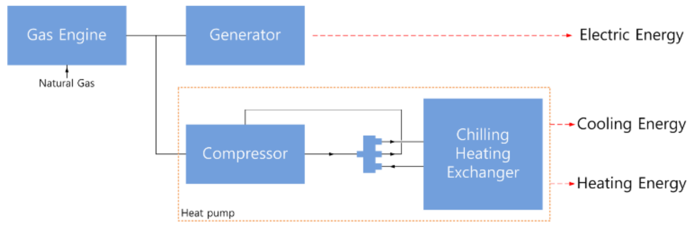
2.1. Trigeneration

As described earlier, trigeneration refers to the generation of chilling, heating, and electrical energy with the use of one energy source. In this process, a gas engine is used to produce chilling, heating, and electricity through the trigen system. A schematic diagram of a trigen system that uses a gas engine is shown in Figure 1.
The trigen system comprises three parts: a gas engine, generator, and a heat pump. Herein, the heat pump is composed of a compressor, a four-way valve, a heat exchanger, an oil separator, a gas–liquid separator, and various valves and switches. The engine drive shaft, generator, and compressor are connected to each other. Thus, when the gas engine is fueled by natural gas during operation, the generator and compressor are operated simultaneously, whereby a power cutoff device protects the system from overloading.
As shown in Table 1, trigen is a heat pump chilling/heating device that generates electricity and chilling or heating simultaneously by operating a compressor and a generator through a gas engine fueled by liquefied petroleum gas or town gas, with a 30 kW power output, 56 kW chilling capacity, and a 67 kW heating capacity.

2.2. TEG

The process of converting the rotational movement of high-pressure gas that passes through an expander is utilized extensively in industrial areas. The most typical example is a cryogenic process used to acquire cold energy. As the temperature drops drastically during the entropy process, wherein a high pressure is converted to work, the cryogenic process is conventionally used for the air liquefaction and separation (ASU). Where air is liquefied to separate nitrogen and oxygen. Additionally, the naphtha cracking center (NCC) (ethylene fabrication process, wherein methane is liquefied) and the liquefied natural gas (LNG) processes (that liquefies natural gas) are also used. Conversely, a TEG system does not consume cold energy; instead, it recovers it in the form of electricity by connecting the rotational movement of the expanded high-pressure gas to the generator.
While the high-pressure gas radially moves in and passes a turbine, the turbine rotates and performs work. In this process, the high-pressure gas is decompressed and exhausted in the axial direction. The variable geometry nozzle (VGN) at the turbine inlet controls the inflow of high-pressure gas by adjusting its angle, thereby controlling the pressure at the outlet of the TEG. In other words, the TEG controls the pressure and produces electricity at the same time.
In the conventional decompression process, each natural gas station forces natural gas through a pressure control valve from P1 (high pressure) to P2 (low pressure). This process is an isenthalpic process, that is, a horizontal movement in the h–s diagram. Conversely, the flow passing through a TEG undergoes a vertical isentropic process. A decompressed fluid passing through the pressure control valve from P1 to P2 has a different temperature from another fluid that is decompressed through the TEG. The pressure control process by the pressure control valve (PCV) is an isenthalpic process; that is, it is a throttle process. In the isenthalpic process, the temperature at the outlet of the PCV decreases owing to the Joule–Thomson effect. The pressure control process by the TEG is an isentropic process, wherein the temperature decrease of a fluid is larger than that caused by the Joule—Thomson effect. When natural gas is decompressed, depending on the composition and state of the gas, the throttle process of the PCV, which is an isenthalpic process, undergoes a temperature drop of 4.5–6 °C for a decompression pressure of 10 bar, while the decompression process of the TEG that is an isentropic process, exhibits a temperature drop in the range of 15–20 °C.
The TEG replaced one of the pressure regulators that had already been installed. Thus, the TEG was installed in parallel with the pressure regulators. The TEG system was configured so that natural gas first flowed into the TEG and then into the pressure regulators when the base load of the TEG was exceeded.
Regarding the natural gas flow at the base load, electrical energy was produced, the TEG conducts voltage control, and the remaining natural gas—which has not been processed by the TEG—flowed to the PCV in parallel with respect to the TEG. Thus, the PCV controls the pressure of natural gas. In addition, if the TEG fails, the shutoff valve of the TEG is closed, and a pressure regulator connected in parallel was operated in a stable manner.
Similar to pressure regulators, a TEG also needs to transfer natural gas at a temperature of 0 °C to customers. For this reason, a heater was installed at the inlet of the TEG. The quantity of heat used for the preheating operation was calculated using the following formula:
Q = q × ρ × c p × T ,
where q denotes the volumetric flow rate of the heated object [m3/s], ρ denotes density [kg/m3], cp denotes specific heat [kJ/kg °C], and ∆T denotes the change in temperature [°C].
In this study, it was assumed that a 75 kW TEG was installed in accordance with the heating capacity of the trigen [3].

3. Energy Optimization Method

This chapter describes the method used to optimize the energy generated through the trigen and TEG introduced in Section 2. The goal was to achieve maximum energy by combining the electrical energy and heat energy obtained from the two systems. Accordingly, for this purpose, the RL technique and deep Q-network technique are introduced.

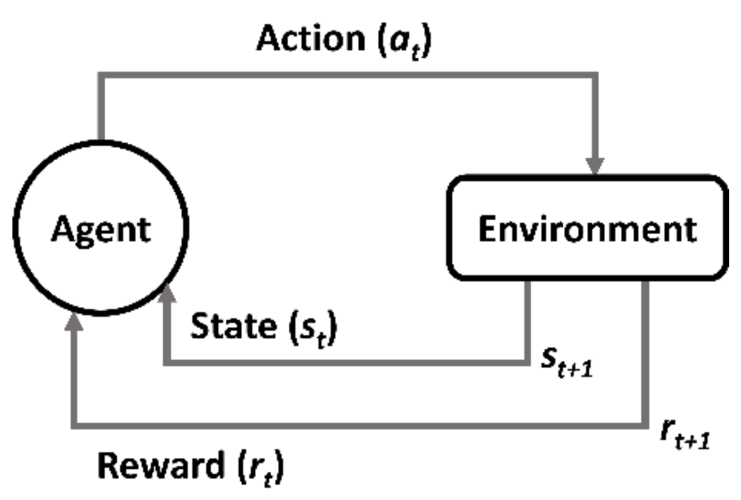
3.1. Reinforced Learning

RL is an area of machine learning concerned with how software agents ought to take actions in an environment to maximize the notion of cumulative reward. RL differs from supervised learning in that it does not require the presentation of labeled input/output pairs nor that suboptimal actions are explicitly corrected. Instead, the focus is on finding a balance between exploration (of uncharted territory) and exploitation (of current knowledge) [36]. The environment is typically stated in the form of a Markov decision process (MDP) because many RL algorithms utilize dynamic programming techniques when used in this context [37]. The main difference between the classical dynamic programming methods and RL algorithms is that the latter do not assume knowledge of an exact mathematical model of the MDP, and they target large MDPs where exact methods become infeasible.
In a typical RL scenario, an agent executes an action in an environment, and this action is interpreted as a reward and a representation of the state. These are then fed back to the agent. This is illustrated in Figure 2, wherein the agent is the learner and the decision maker. The environment is the entity with which the agent interacts, comprising everything apart (and outside of) the agent. The action involves all the possible moves that the agent can make. The state is the current situation returned by the environment. The reward is an immediate return value from the environment to evaluate the last action by the agent.
At every time step t, the agent executes action at and receives the state st and scalar reward rt. The environment receives action at, transmits state st+1, and receives a reward rt+1 at every time step. Each action influences the agent’s future state. Success is measured by a scalar reward signal, and RL selects actions to maximize future rewards. The agent employs a strategy, policy (π), to determine the next action based on the current state. A policy, expressed as π(s, a), describes a probable action path. Specifically, it is a function that takes in a state and an action and returns the probability of taking that action in that state.
π : A × S 0 ,   1 , π a ,   s = P ( a t = a   |   s t = s )
where P is the probability of action a in state s. The value function Vπ(s) is defined as the expected return starting with state s, that is, s0 = s, and successively following policy π. Hence, the value function estimates how good it is to be in a given state.
V π s = E π R t | s t = s = E π k = 0 γ k r t + k + 1 | s t = s , 0 γ 1 ,
where E is the expected (future) cumulative reward, R is the sum of future discounted rewards, rt is the immediate reward, and γ is the discount factor (this is smaller than unity). As a particular state becomes older, its effect on the later states becomes progressively less, and its effect is thus discounted. Although the range of immediate reward is not specified, having a positive value means that the action is a recommended action, and having a negative value means that the action is an action that is not recommended. It also means more recommended or more non-recommended action depending on its absolute size.
The Q-value function at state s that executes action a is the expected cumulative reward from taking action a in state s. The Q-value function estimates how good the state–action pair is.
Q π s ,   a = E π R t | s t = s , a t = a   = E π k = 0 γ k r t + k + 1 | s t = s , a t = a ,
The optimal Q-value function Q*(s, a) is the maximum expected cumulative reward achievable from a given state–action pair. The concept of the optimal Q-value function is illustrated in Figure 3.
Q s , a = max π E t 0 γ t r t | s 0 = s , a 0 = a , π
To obtain the optimal Q-value, RL breaks the decision problem into smaller subproblems. Bellman’s principle of optimality describes how this is achieved [37]. It is stated as follows: an optimal policy has the property that whatever the initial state and initial decision are, the remaining decisions must constitute an optimal policy with regard to the state resulting from the first decision.
The Bellman equation is classified as a functional equation because solving it requires finding the unknown function V which is the value function. Recall that the value function describes the best possible value of the objective as a function of state s. By calculating the value function, the function that describes the optimal action as a function of the state is also found. This is called the policy function. Equations (6)–(9) describe this process:
V π s = R s , π s + γ s P s | s , π s V π s ,
V π s = max a R s , a + γ s P s | s , a V π s ,
V π s = a A π a | s q π s , a ,
q π s , a = γ s P π s s V π s ,
By expressing the above equations as recursive functions and calculating them repeatedly, the optimal value can be obtained. When performing repetitive calculations, the action that brings the maximum value to each state is selected, and these are summed and moved to the direction with the highest value. Or, for a situation in which the future value is the largest, the value is searched so that the present maximum value appears. This is called back propagation.

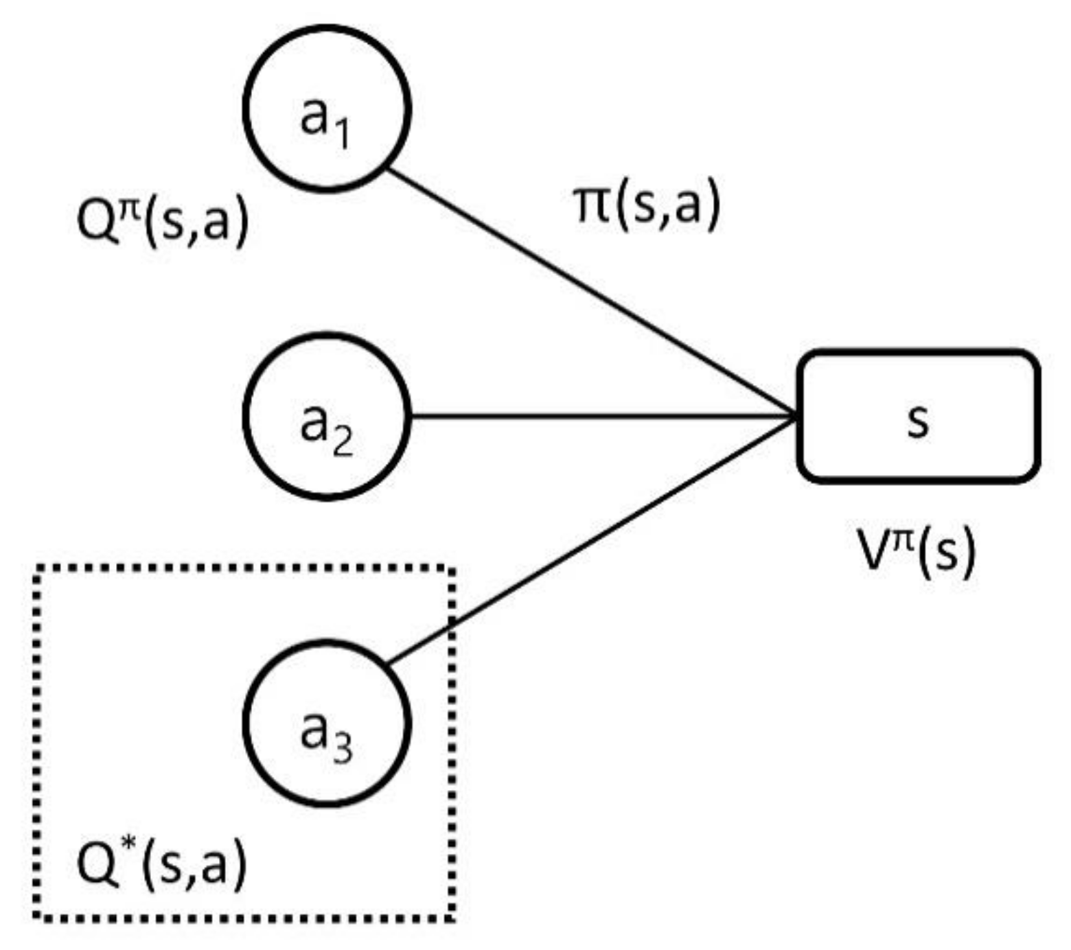
3.2. Deep Q-Network Algorithm

Before explaining the deep Q-network, Q-learning is described. Each agent repeats the following steps to maximize the Q-value:
  • Choose an action a in the current state, s.
  • Perform action and receive the reward R(s, a).
  • Observe the new state S(s, a).
  • Update: Q’(s, a) ← R(s, a) + γmax{Q’(S(s, a), a)}
Based on the above process, known as greedy action selection, an action that maximizes the Q-value is selected. However, if the action that maximizes the Q-value is only considered, the opportunity to learn about various environmental changes would be lost. As a result, optimization may fail. Therefore, using the ε-greedy method, we explore nongreedy actions with a certain probability (ε) to learn about the various situations. At this time, it is very important to maintain a balance between greedy actions and nongreedy actions to obtain optimal results. In general, selecting a greedy action is called exploiting, and selecting a non-greedy action is called exploration. When searching for the best results, exploration is very important, meaning that pursuing only the best results does not always bring about good results.
A deep Q-network can be thought of as a form that combines artificial intelligence learning by combining a neural network with Q-learning. There are two types of deep Q-network methods. One is a method that receives state and action as inputs and outputs the Q function value of the state and action. The other is a neural network that receives only the state as input and outputs the Q function value for each action at once through a feedforward process. Here, we use a neural network type that receives both state and action and outputs the Q function value. To formulate this to create an algorithm, the Q-value function is first approximated to the Q-network.
Q s , a , θ Q π s , a ,
If the objective function is developed in the direction that reduces the difference between the current Q-value and the target Q-value in the mean-squared error (MSE) method, the equation is as follows,
L i θ i = E s , a , r , s ~ U D ( P r e d i c t e d max Q v a l u e ) c u r r e n t   Q v a l u e 2 ,
L i θ i = E s , a , r , s ~ U D r + γ max a Q ( s , a ; θ i ) Q ( s , a ; θ i 2
where U(D) is the replay memory, θ is a neural network parameter, and θ is the old parameter.
Using the above equation, the gradient descent method is applied to determine the optimum value. The replay memory D that appears here is referred to as experience replay, and stores a dataset of the agent’s experience (but excludes other relationships). If the reward rt is received after selecting the action at state st, and the new state being observed is st+1, the transition (st, at, rt, st+1) is stored in the replay memory, D. The transitions stored in the memory are used to optimize the MSE, and in some cases, the minibatch is partially executed to improve the speed and improve the optimization result.
Algorithm 1 describes an algorithm that performs Deep Q-network using replay memory, D. It initializes memory D, Q-function, and target Q-function, then randomly selects an action and inputs the result to memory D. Of the D thus obtained, minibatch is executed again to perform an action that obtains an optimal value. The action, reward, and policy used at this time will be described in the next section.
Algorithm 1: Deep Q-Network Algorithm
1. Initialize replay memory D to capacity N
2. Initialize action–value function Q with θ
3. Initialize target action–value function Q with θ = θ
4. For episode = 1 to num episodes do
5. For t = 1 to T do
6. With probability ε select a random action at, otherwise select at = maxaQ(s, a; θ)
7. Execute action at in emulator and observe reward rt and state st
8. Store transition (st, at, rt, st+1) in D
9. Sample random minibatch of transitions (sj, aj, rj, sj+1) from D
10. Perform a gradient descent step on Lj(θ) with respect to the network parameters θ
11. End For
12. End For

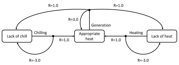
3.3. Action, Reward, and Policy

The prerequisite for the operation of this system is to provide an adequate amount of heat. This is because the temperature of the compressed gas must be raised above a certain temperature for the TEG to generate power. In addition, TEG serves as a decompression facility by default even if it does not generate power; hence, the temperature of the compressed gas must be raised to provide gas to households. Accordingly, it is essential to supply an adequate amount of heat.
With a proper amount of heat supplied, the TEG can generate maximum power, and trigen can generate additional power by using the remaining power capacity. As this is not a prerequisite for the system used in the research to have an independent microgrid configuration, the power output to be supplied to the system is not limited; thus, the greater the power generation amount is, the better it is. This is possible subject to the precondition that the system is linked to a commercial system that can infinitely receive the generated power.
Therefore, subject to the situation wherein heat energy is adequately supplied, the establishment of a policy for maximum output, and the action and reward can be expressed according to the following Figure 4.
There are three different states: appropriate heat, lack of chills, and lack of heat. The final target is to reach an appropriate heat state, and power generation can only be attempted at this state. Therefore, with an attempt for power generation, all cases are rewarded, and a reward of 3.0 is given to those returning to the appropriate heat, the most recommended action and state. Even if the state lacks chills or lacks heat after power generation, a reward of 1.0 is provided, as the power generation itself is a recommended action.
In the absence of chills, the state is allowed to change to an appropriate heat through chilling; however, if the state remains at a lack of chills even after chilling is applied, it is rewarded with −3.0 to avoid this situation.
Similarly, in a state lacking heat, the state is allowed to change to an appropriate heat state through heating, but if the state remains unchanged (that is, lacks heat), even after heating is applied, the policy is designed to give a reward of −3.0 to discourage and avoid this action.

4. Case Study

A simulation was conducted to confirm the benefits of optimized operation by combining trigen to TEG and by using RL compared with the existing TEG exclusive system. In this process, the aforementioned MDP [37] was applied mutatis mutandis, and MSE [36] was used as it was as a mathematical model. The tool used for the analysis was TensorFlow engine [49]. Assuming that the thermal energy needed for this system is unnecessary elsewhere, and is used only with TEG, the required thermal energy is determined by the flow rate of the gas entering the TEG. Figure 5 shows the flow rate of gas at a gas station wherein the TEG is scheduled to be installed.
Figure 6 shows the power output that can be generated through the TEG in such a flow pattern. When the flow rate exceeds a certain amount, power generation is always available with the exceptional case of failure; hence, an operation rate of 100% is assumed. The annual power output that can be generated is 624 MWh, and the required annual quantity of heat is 595 MWh [3]. Both the power output and required quantity of heat are dependent on the average monthly gas flow rate, and they are all different depending on the situation.
In winter, the flow rate is high because the amount of gas usage is high, but the required amount of heat is also high because the outside temperature is low.
Assuming that the required amount of heat is provided by trigen, and the maximum power output is provided by RL, The average monthly power simulation results are shown in Figure 7. Compared with the exclusive generation by TEG, the results show that the power output increases, and the variation of average monthly power output decreases.
The required amount of heat can be calculated using Equation (1), and the calculated heat is supplied by trigen. According to the results in Figure 7, when the flow rate is high, the power output of the TEG is large; however, the required amount of heat increases that in turn reduces the power output of the trigen. When the power output of the TEG decreases, the required amount of heat decreases accordingly, thus providing trigen the capacity to generate electricity. In turn, the overall power output remains at a similar level.
In addition, the amount of heat supply and power output of trigen can be optimized to maximize the power output obtained by using the RL technique. The power output cannot be optimized with the existing simple combined cycle power plant TEG + trigen; thus, there is no significant increase in the power output. However, by applying RL to TEG + trigen as a means of optimizing operation, it is confirmed that the overall power output is maximized.
The overall power generation efficiency obtained is summarized in Table 2. The power generation efficiency increased significantly when TEG and trigen were used compared with TEG alone, and further increased based on the application of RL to determine the optimal operation method. The energy generation efficiency was calculated using Equation (13) by estimating the generated power output and gas consumption.
η o u t = 3.6 × P e × 100 ÷ H f × F f ,
where ηout represents the total power generation efficiency [%], Pe represents the generated power output [kW], Hf represents the heat output of fuel [MJ/Nm3], and Ff represents the gas consumption [Nm3/h].

5. Conclusions

In this study, TEG and trigen were employed to improve the total power generation efficiency, and a method of applying the RL technique was presented to maximize the power output. The energy efficiency was enhanced when trigen provided the required heat for power generation in TEG, and additional power was generated based on the capacity of trigen, whereby the total energy efficiency was maximized according to the improvement of the efficiency of the overall power generation system and the maximization of the power output. In particular, it was confirmed that the total energy efficiency was improved by 3% when the operation was optimized using the RL technique rather than simple TEG + trigen.
Currently, application of the RL technique to optimize operation simply maximized the power output. However, a more precise operation method was expected to be derived by reflecting the characteristics of the gas flow rate, temperature, and gas usage pattern of the location at which the TEG was installed. In the future, it is anticipated that power generation systems using TEG and trigen will be expanded and installed in gas gate stations. It is expected that the methods for configuring MGs for each system and the construction of a comprehensive power generation system based on the integration of the entire operation could then be studied.

Author Contributions

Conceptualization, S.H. and G.S.S.; methodology, G.S.S.; software, S.H.; validation, G.S.S. and H.T.K.; formal analysis, S.H.; investigation, S.H.; resources, G.S.S. and H.T.K.; writing—original draft preparation, G.S.S.; writing—review and editing, S.H.; project administration, H.T.K.; funding acquisition, H.T.K. and S.H. All authors have read and agreed to the published version of the manuscript.

Funding

This research was funded by Korea Institute of Energy Technology Evaluation and Planning, grant number 20193510100040 and Korea Electric Power Corporation, grant number R18XA06-65.

Conflicts of Interest

The authors declare no conflict of interest.

References

  1. Third Energy Master Plan. 2019. Available online: https://www.etrans.or.kr/ebook/05/files/assets/common/downloads/Third%20Energy%20Master%20Plan.pdf (accessed on 12 October 2020).
  2. Xie, D.; Chen, A.; Gu, C.; Tai, J. Time-domain modeling of grid-connected CHP for its interaction with the power grid. IEEE Tran. Power Syst. 2018, 33, 6430–6440. [Google Scholar] [CrossRef]
  3. KOGAS Research Institute, Localization of TEG technical plan (plan) service, Technical Report, October. 2015. Available online: http://www.kogas.or.kr/portal/downloadBbsFile.do?atchmnflNo=26421 (accessed on 17 August 2016).
  4. Kim, H.; You, H.; Choi, K.; Han, S. A study on interconnecting to the power grid of new energy using the natural gas pressure. J. Electr. Eng. Technol. 2020, 15, 307–314. [Google Scholar] [CrossRef]
  5. Hong, S.; Kim, K.; You, H.; Ha, J. Research articles: Turbo expander power generation using pressure drop at valve station in natural gas transportation pipeline. J. Korean Inst. Gas 2012, 16, 1–7. [Google Scholar]
  6. Lin, C.; Wu, W.; Wang, B.; Shahidehpour, M.; Zhang, B. Joint commitment of generation units and heat exchange stations for combined heat and power systems. IEEE Trans. Sustain. Energy 2020, 11, 1118–1127. [Google Scholar] [CrossRef]
  7. Li, Z.; Wu, W.; Wang, J.; Zhang, B.; Zheng, T. Transmission-constrained unit commitment considering combined electricity and district heating networks. IEEE Trans. Sustain. Energy 2016, 7, 480–492. [Google Scholar] [CrossRef]
  8. Wang, J.; Zhong, H.; Tan, C.; Chen, X.; Rajagopal, R.; Xia, Q.; Kang, C. Economic benefits of integrating solar-powered heat pumps into a CHP system. IEEE Trans. Sustain. Energy 2018, 9, 1702–1712. [Google Scholar] [CrossRef]
  9. Zhou, Y.; Hu, W.; Min, Y.; Dai, Y. Integrated power and heat dispatch considering available reserve of combined heat and power units. IEEE Trans. Sustain. Energy 2019, 10, 1300–1310. [Google Scholar] [CrossRef]
  10. Yao, S.; Gu, W.; Zhou, S.; Lu, S.; Wu, C.; Pan, G. Hybrid timescale dispatch hierarchy for combined heat and power system considering the thermal inertia of heat sector. IEEE Access 2018, 6, 63033–63044. [Google Scholar] [CrossRef]
  11. Liu, B.; Li, J.; Zhang, S.; Gao, M.; Ma, H.; Li, G.; Gu, C. Economic dispatch of combined heat and power energy systems using electric boiler to accommodate wind power. IEEE Access 2020, 8, 41288–41297. [Google Scholar] [CrossRef]
  12. Dai, Y.; Chen, L.; Min, Y.; Chen, Q.; Hu, K.; Hao, J.; Xu, F. Dispatch model of combined heat and power plant considering heat transfer process. IEEE Trans. Sustain. Energy 2017, 8, 1225–1236. [Google Scholar] [CrossRef]
  13. Cao, Y.; Wei, W.; Wu, L.; Mei, S.; Shahidehpour, M.; Li, Z. Decentralized operation of interdependent power distribution network and district heating network: A market-driven approach. IEEE Trans. Smart Grid. 2019, 10, 5374–5385. [Google Scholar] [CrossRef]
  14. Dai, Y.; Chen, L.; Min, Y.; Mancarella, P.; Chen, Q.; Hao, J.; Xu, F. A general model for thermal energy storage in combined heat and power dispatch considering heat transfer constraints. IEEE Trans. Sustain. Energy 2018, 9, 1518–1528. [Google Scholar] [CrossRef]
  15. Lin, C.; Wu, W.; Zhang, B.; Sun, Y. Decentralized solution for combined heat and power dispatch through benders decomposition. IEEE Trans. Sustain. Energy 2017, 8, 1361–1372. [Google Scholar] [CrossRef]
  16. Yang, J.; Zhang, N.; Botterud, A.; Kang, C. On an equivalent representation of the dynamics in district heating networks for combined electricity-heat operation. IEEE Trans. Power Syst. 2020, 35, 560–570. [Google Scholar] [CrossRef]
  17. Gao, Y.; Zeng, D.; Zhang, L.; Hu, Y.; Xie, Z. Research on modeling and deep peak regulation control of a combined heat and power unit. IEEE Access 2020, 8, 91546–91557. [Google Scholar] [CrossRef]
  18. Li, J.; Lin, J.; Song, Y.; Xing, X.; Fu, C. Operation optimization of power to hydrogen and heat (P2HH) in ADN coordinated with the district heating network. IEEE Trans. Sustain. Energy 2019, 10, 1672–1683. [Google Scholar] [CrossRef]
  19. Deng, B.; Teng, Y.; Hui, Q.; Zhang, T.; Qian, X. Real-coded quantum optimization-based bi-level dispatching strategy of integrated power and heat systems. IEEE Access 2020, 8, 47888–47899. [Google Scholar] [CrossRef]
  20. Ivanova, P.; Sauhats, A.; Linkevics, O. District heating technologies: Is it chance for CHP plants in variable and competitive operation conditions? IEEE Trans. Ind. Appl. 2019, 55, 35–42. [Google Scholar] [CrossRef]
  21. Rong, A.; Luh, P.B. A dynamic regrouping based dynamic programming approach for unit commitment of the transmission-constrained multi-site combined heat and power system. IEEE Trans. Power Syst. 2018, 33, 714–722. [Google Scholar] [CrossRef]
  22. Xue, Y.; Li, Z.; Lin, C.; Guo, Q.; Sun, H. Coordinated dispatch of integrated electric and district heating systems using heterogeneous decomposition. IEEE Trans. Sustain. Energy 2020, 11, 1495–1507. [Google Scholar] [CrossRef]
  23. Dai, Y.; Chen, L.; Min, Y.; Mancarella, P.; Chen, Q.; Hao, J.; Xu, F. Integrated dispatch model for combined heat and power plant with phase-change thermal energy storage considering heat transfer process. IEEE Trans. Sustain. Energy 2018, 9, 1234–1243. [Google Scholar] [CrossRef]
  24. Zhou, Y.; Shahidehpour, M.; Wei, Z.; Li, Z.; Sun, G.; Chen, S. Distributionally robust co-optimization of energy and reserve for combined distribution networks of power and district heating. IEEE Trans. Power Syst. 2020, 35, 2388–2398. [Google Scholar] [CrossRef]
  25. Virasjoki, V.; Siddiqui, A.S.; Zakeri, B.; Salo, A. Market power with combined heat and power production in the Nordic energy system. IEEE Trans. Power Syst. 2018, 33, 5263–5275. [Google Scholar] [CrossRef] [Green Version]
  26. Zhou, H.; Li, Z.; Zheng, J.H.; Wu, Q.H.; Zhang, H. Robust scheduling of integrated electricity and heating system hedging heating network uncertainties. IEEE Trans. Smart Grid. 2020, 11, 1543–1555. [Google Scholar] [CrossRef]
  27. Teng, Y.; Sun, P.; Leng, O.; Chen, Z.; Zhou, G. Optimal operation strategy for combined heat and power system based on solid electric thermal storage boiler and thermal inertia. IEEE Access 2019, 7, 180761–180770. [Google Scholar] [CrossRef]
  28. Rigo-Mariani, R.; Zhang, C.; Romagnoli, A.; Kraft, M.; Ling, K.V.; Maciejowski, J. A combined cycle gas turbine model for heat and power dispatch subject to grid constraints. IEEE Trans. Sustain. Energy 2020, 11, 448–456. [Google Scholar] [CrossRef]
  29. Tan, B.; Chen, H. Stochastic multi-objective optimized dispatch of combined chilling, heating, and power microgrids based on hybrid evolutionary optimization algorithm. IEEE Access 2019, 7, 176218–176232. [Google Scholar] [CrossRef]
  30. Nazari-Heris, M.; Mohammadi-Ivatloo, B.; Gharehpetian, G.B.; Shahidehpour, M. Robust short-term scheduling of integrated heat and power microgrids. IEEE Syst. J. 2019, 13, 3295–3303. [Google Scholar] [CrossRef]
  31. Liu, N.; Wang, J.; Wang, L. Hybrid energy sharing for multiple microgrids in an integrated heat–electricity energy system. IEEE Trans. Sustain. Energy 2019, 10, 1139–1151. [Google Scholar] [CrossRef]
  32. Koch, K.; Alt, B.; Gaderer, M. Dynamic modeling of a decarbonized district heating system with CHP plants in electricity-based mode of operation. Energies 2020, 13, 4134. [Google Scholar] [CrossRef]
  33. Olabi, A.; Wilberforce, T.; Sayed, E.T.; Elsaid, K.; Abdelkareem, M.A. Prospects of fuel cell combined heat and power systems. Energies 2020, 13, 4104. [Google Scholar] [CrossRef]
  34. Calise, F.; Cappiello, F.L.; Dentice d’Accadia, M.; Libertini, L.; Vicidomini, M. Dynamic simulation and thermoeconomic analysis of a trigeneration system in a hospital application. Energies 2020, 13, 3558. [Google Scholar] [CrossRef]
  35. Li, W.; Li, T.; Wang, H.; Dong, J.; Li, Y.; Cui, D.; Ge, W.; Yang, J.; Onyeka Okoye, M. Optimal dispatch model considering environmental cost based on combined heat and power with thermal energy storage and demand response. Energies 2019, 12, 817. [Google Scholar] [CrossRef] [Green Version]
  36. Kaelbling, L.P.; Littman, M.L.; Moore, A.W. Reinforcement learning: A survey. J. Artif. Intel. Res. 1996, 4, 237–285. [Google Scholar] [CrossRef] [Green Version]
  37. Zhang, Z.; Yao, R.; Huang, S.; Chen, Y.; Mei, S.; Sun, K. An online search method for representative risky fault chains based on reinforcement learning and knowledge transfer. IEEE Trans. Power Syst. 2020, 35, 1856–1867. [Google Scholar] [CrossRef]
  38. Nguyen, K.K.; Duong, T.Q.; Vien, N.A.; Le-Khac, N.; Nguyen, M. Non-cooperative energy efficient power allocation game in D2D communication: A multi-agent deep reinforcement learning approach. IEEE Access 2019, 7, 100480–100490. [Google Scholar] [CrossRef]
  39. Jang, B.; Kim, M.; Harerimana, G.; Kim, J.W. Q-Learning algorithms: A comprehensive classification and applications. IEEE Access 2019, 7, 133653–133667. [Google Scholar] [CrossRef]
  40. Ferreira, L.R.; Aoki, A.R.; Lambert-Torres, G. A reinforcement learning approach to solve service restoration and load management simultaneously for distribution networks. IEEE Access 2019, 7, 145978–145987. [Google Scholar] [CrossRef]
  41. Gan, X.; Guo, H.; Li, Z. A new multi-agent reinforcement learning method based on evolving dynamic correlation matrix. IEEE Access 2019, 7, 162127–162138. [Google Scholar] [CrossRef]
  42. Park, Y.J.; Lee, Y.J.; Kim, S.B. Cooperative multi-agent reinforcement learning with approximate model learning. IEEE Access 2020, 8, 125389–125400. [Google Scholar] [CrossRef]
  43. Silva, F.L.D.; Nishida, C.E.H.; Roijers, D.M.; Costa, A.H.R. Coordination of electric vehicle charging through multiagent reinforcement learning. IEEE Trans. Smart Grid. 2020, 11, 2347–2356. [Google Scholar] [CrossRef]
  44. Wang, W.; Yu, N.; Gao, Y.; Shi, J. Safe off-policy deep reinforcement learning algorithm for Volt-VAR control in power distribution systems. IEEE Trans. Smart Grid. 2020, 11, 3008–3018. [Google Scholar] [CrossRef]
  45. Xu, H.; Domínguez-García, A.D.; Sauer, P.W. Optimal tap setting of voltage regulation transformers using batch reinforcement learning. IEEE Trans. Power Syst. 2020, 35, 1990–2001. [Google Scholar] [CrossRef] [Green Version]
  46. Xu, X.; Jia, Y.; Xu, Y.; Xu, Z.; Chai, S.; Lai, C.S. A multi-agent reinforcement learning-based data-driven method for home energy management. IEEE Trans. Smart Grid. 2020, 11, 3201–3211. [Google Scholar] [CrossRef] [Green Version]
  47. Yan, Z.; Xu, Y. Data-driven load frequency control for stochastic power systems: A deep reinforcement learning method with continuous action search. IEEE Trans. Power Syst. 2019, 34, 1653–1656. [Google Scholar] [CrossRef]
  48. Yan, Z.; Xu, Y. Real-time optimal power flow: A Lagrangian based deep reinforcement learning approach. IEEE Trans. Power Syst. 2020, 35, 3270–3273. [Google Scholar] [CrossRef]
  49. Bregar, K.; Mohorčič, M. Improving indoor localization using convolutional neural networks on computationally restricted devices. IEEE Access 2018, 6, 17429–17441. [Google Scholar] [CrossRef]
Figure 1. Schematic diagram of a trigen system.
Sustainability 12 08379 g001
Figure 2. Concept of reinforcement learning.
Sustainability 12 08379 g002
Figure 3. Concept of optimal Q-value function. (Qπ(s, a): Q-value function, Q*(s, a): optimal Q-value function, π(s, a): policy, Vπ(s): value function, an: action, s: state).
Sustainability 12 08379 g003
Figure 4. Schematic representing the concept of optimal Q-value function. (R: reward for each action).
Sustainability 12 08379 g004
Figure 5. Monthly gas flow.
Sustainability 12 08379 g005
Figure 6. Monthly average generation and required heat.
Sustainability 12 08379 g006
Figure 7. Comparison of average monthly generation with reinforcement learning (RL).
Sustainability 12 08379 g007
Table 1. Detailed specifications of trigen.
ItemTypeUnitSpec
PerformanceChilling Capacitykcal/h48,160
kW56
Heating Capacitykcal/h57,620
kW67
Power OutputkW30
Power ConsumptionChillingkW1.1
HeatingkW1.02
Operating CurrentChillingA6.1
HeatingA5.8
Fuel ConsumptionGas Type N-13
ChillingkW69
HeatingkW69
Operating TemperatureChilling −10–50 °C
Heating −20–20 °C
Table 2. Comparison of total power generation efficiency.
LabelTEGTEG + TrigenTEG + Trigen with RL
ηout (%)79%85%88%

